EP4033167A1 - Ventilation assembly and air conditioning apparatus - Google Patents
Ventilation assembly and air conditioning apparatus Download PDFInfo
- Publication number
- EP4033167A1 EP4033167A1 EP21182293.7A EP21182293A EP4033167A1 EP 4033167 A1 EP4033167 A1 EP 4033167A1 EP 21182293 A EP21182293 A EP 21182293A EP 4033167 A1 EP4033167 A1 EP 4033167A1
- Authority
- EP
- European Patent Office
- Prior art keywords
- mounting port
- volute
- sealing member
- mounting
- ventilation assembly
- Prior art date
- Legal status (The legal status is an assumption and is not a legal conclusion. Google has not performed a legal analysis and makes no representation as to the accuracy of the status listed.)
- Granted
Links
Images




Classifications
-
- B—PERFORMING OPERATIONS; TRANSPORTING
- B01—PHYSICAL OR CHEMICAL PROCESSES OR APPARATUS IN GENERAL
- B01D—SEPARATION
- B01D46/00—Filters or filtering processes specially modified for separating dispersed particles from gases or vapours
- B01D46/0002—Casings; Housings; Frame constructions
- B01D46/0005—Mounting of filtering elements within casings, housings or frames
- B01D46/0006—Filter elements or cartridges installed in a drawer-like manner
-
- F—MECHANICAL ENGINEERING; LIGHTING; HEATING; WEAPONS; BLASTING
- F24—HEATING; RANGES; VENTILATING
- F24F—AIR-CONDITIONING; AIR-HUMIDIFICATION; VENTILATION; USE OF AIR CURRENTS FOR SCREENING
- F24F13/00—Details common to, or for air-conditioning, air-humidification, ventilation or use of air currents for screening
- F24F13/28—Arrangement or mounting of filters
-
- B—PERFORMING OPERATIONS; TRANSPORTING
- B01—PHYSICAL OR CHEMICAL PROCESSES OR APPARATUS IN GENERAL
- B01D—SEPARATION
- B01D46/00—Filters or filtering processes specially modified for separating dispersed particles from gases or vapours
- B01D46/10—Particle separators, e.g. dust precipitators, using filter plates, sheets or pads having plane surfaces
- B01D46/16—Particle separators, e.g. dust precipitators, using filter plates, sheets or pads having plane surfaces arranged on non-filtering conveyors or supports
-
- B—PERFORMING OPERATIONS; TRANSPORTING
- B01—PHYSICAL OR CHEMICAL PROCESSES OR APPARATUS IN GENERAL
- B01D—SEPARATION
- B01D46/00—Filters or filtering processes specially modified for separating dispersed particles from gases or vapours
- B01D46/42—Auxiliary equipment or operation thereof
- B01D46/4227—Manipulating filters or filter elements, e.g. handles or extracting tools
-
- F—MECHANICAL ENGINEERING; LIGHTING; HEATING; WEAPONS; BLASTING
- F24—HEATING; RANGES; VENTILATING
- F24F—AIR-CONDITIONING; AIR-HUMIDIFICATION; VENTILATION; USE OF AIR CURRENTS FOR SCREENING
- F24F1/00—Room units for air-conditioning, e.g. separate or self-contained units or units receiving primary air from a central station
- F24F1/0007—Indoor units, e.g. fan coil units
- F24F1/0071—Indoor units, e.g. fan coil units with means for purifying supplied air
- F24F1/0073—Indoor units, e.g. fan coil units with means for purifying supplied air characterised by the mounting or arrangement of filters
-
- F—MECHANICAL ENGINEERING; LIGHTING; HEATING; WEAPONS; BLASTING
- F24—HEATING; RANGES; VENTILATING
- F24F—AIR-CONDITIONING; AIR-HUMIDIFICATION; VENTILATION; USE OF AIR CURRENTS FOR SCREENING
- F24F7/00—Ventilation
- F24F7/003—Ventilation in combination with air cleaning
-
- B—PERFORMING OPERATIONS; TRANSPORTING
- B01—PHYSICAL OR CHEMICAL PROCESSES OR APPARATUS IN GENERAL
- B01D—SEPARATION
- B01D2271/00—Sealings for filters specially adapted for separating dispersed particles from gases or vapours
- B01D2271/02—Gaskets, sealings
-
- B—PERFORMING OPERATIONS; TRANSPORTING
- B01—PHYSICAL OR CHEMICAL PROCESSES OR APPARATUS IN GENERAL
- B01D—SEPARATION
- B01D2279/00—Filters adapted for separating dispersed particles from gases or vapours specially modified for specific uses
- B01D2279/35—Filters adapted for separating dispersed particles from gases or vapours specially modified for specific uses for venting arrangements
-
- B—PERFORMING OPERATIONS; TRANSPORTING
- B01—PHYSICAL OR CHEMICAL PROCESSES OR APPARATUS IN GENERAL
- B01D—SEPARATION
- B01D2279/00—Filters adapted for separating dispersed particles from gases or vapours specially modified for specific uses
- B01D2279/50—Filters adapted for separating dispersed particles from gases or vapours specially modified for specific uses for air conditioning
Definitions
- the present disclosure relates to a field of air conditioning technologies, and in particular to a ventilation assembly and an air conditioning apparatus.
- an air-conditioning apparatus has a ventilation assembly configured to realize a fresh air function of indoor and outdoor air exchange.
- the air-conditioning apparatus having the ventilation assembly operates in an environment with a large temperature difference between indoor and outdoor, due to the poor sealing performance of the ventilation assembly, condensation often appears on the ventilation assembly, and drips to the floor and wall, thus damaging the indoor home environment and affecting the user experience.
- the present disclosure provides a ventilation assembly and an air conditioning apparatus.
- a ventilation assembly including: a volute, a surface of the volute being provided with a mounting port; a filter assembly arranged in the mounting port or in a portion of the volute adjacent to the mounting port; and a sealing member arranged with the mounting port or with the portion of the volute adjacent to the mounting port, and configured to seal a gap between the filter assembly and the mounting port.
- the sealing member has a shape substantially the same with a shape of the gap between the filter assembly and the mounting port.
- the filter assembly includes a bracket, a part of the bracket adjacent to the mounting port is configured to have a shape substantially the same with a shape of the mounting port to cover the mounting port, and the sealing member is arranged between the bracket and the volute and has a shape substantially the same with a shape of a gap between the bracket and the mounting port.
- a positioning groove is provided at the mounting port of the volute along a periphery of the mounting port, and the sealing member is arranged in the positioning groove.
- a thickness of the sealing member is slightly larger than a width of the positioning groove, so that the sealing member is clamped in the positioning groove through an interference fit with the positioning groove.
- a difference between inner and outer radiuses of the sealing member is slightly greater than a distance between a top and a bottom of the positioning groove, so that the sealing member is in an interference fit with the filter assembly.
- a first positioning rib and a second positioning rib are provided at the mounting port of the volute, and the positioning groove is formed between the first positioning rib and the second positioning rib.
- a distance between an end face of the first positioning rib facing the mounting port and an end face of the first positioning rib connected to the volute is smaller than a difference between inner and outer radiuses of the sealing member; a distance between an end face of the second positioning rib facing the mounting port and an end face of the second positioning rib connected to the volute is larger than the difference between the inner and outer radiuses of the sealing member.
- an air channel communicated with the mounting port is provided in the volute.
- the bracket includes: a mounting part having a shape substantially the same with the shape of the mounting port to cover the mounting port; and a supporting part connected with the mounting part, arranged in the air channel, and configured to support a filter screen fixedly connected with the supporting part.
- the sealing member is arranged between the mounting part and the volute.
- the bracket further includes an operating member arranged with a surface facing away from the air channel.
- the filter assembly is arranged transversely in the air channel, and a sectional area of the filter assembly is greater than or equal to a sectional area of the air channel.
- the ventilation assembly further includes a fan assembly arranged in the volute and configured to drive air to flow by rotation, and the fan assembly has an air output surface communicated with the air channel.
- the ventilation assembly further includes a fastening structure
- the fastening structure includes a first fastener arranged with the volute and a second fastener arranged with the filter assembly, and the first fastener and the second fastener are configured to be engaged with each other to prevent the filter assembly from being separated from the volute.
- the first fastener includes a snap
- the second fastener includes a protrusion or a mounting groove
- the snap is configured to be engaged with the protrusion or the mounting groove.
- an air conditioning apparatus including the ventilation assembly according to the first aspect of the present disclosure.
- the sealing member is used for sealing the gap between the filter assembly and the mounting port, so that the sealing performance at the mounting port is improved, the air flow entering the volute from the outside is prevented from leaking out from the gap between the filter assembly and the volute when the ventilation assembly operates, the condensation generated when the ventilation assembly operates in an environment with a large temperature difference between indoor and outdoor is greatly reduced, and the user experience is improved.
- a ventilation assembly is provided in an indoor unit 100 of the air conditioner, one end of an air input pipe 150 of the indoor unit 100 is communicated with the ventilation assembly, and the other end of the air input pipe 150 is connected with a wind shield 160 for guiding an air flow from an outdoor environment into the air input pipe 150.
- a cold air flow entering the ventilation assembly may leak out from a gap of the ventilation assembly due to a poor sealing condition of the ventilation assembly in the related art.
- Warm air in the air conditioning apparatus liquefies when it meets the cold air flow, thereby resulting in condensation.
- the condensation can form water droplets, which may drip to an indoor floor of a user, and even flow to a wall to form water stains, thus affecting the user experience.
- a ventilation assembly including a volute 110, a filter assembly 170, and a sealing member 130.
- a surface of the volute 110 is provided with a mounting port 111.
- the filter assembly 170 is arranged in the mounting port 111 or in a portion of the volute 110 adjacent to the mounting port 111.
- the filter assembly 170 is configured to filter out pollutant particles such as dust or smoke in air flowing through an air channel 115 so as to purify the air.
- the sealing member 130 is positioned at the mounting port 111 or at the portion of the volute 110 adjacent to the mounting port 111, and is configured to seal a gap between the filter assembly 170 and the mounting port 111. Or, the sealing member 130 is located between the filter assembly and the volute, and cooperates with the filter assembly to seal the mounting port.
- the sealing member 130 can seal the gap between the filter assembly 170 and the mounting port 111, so as to enhance the sealing performance at the mounting port 111, and prevent the air flow entering the volute from the outside from leaking out from the gap between the filter assembly 170 and the volute 110 when the ventilation assembly operates, thus greatly reducing the condensation generated when the temperature difference between indoor and outdoor is large, and improving the user experience.
- the ventilation assembly further includes a fan assembly 140 arranged in the volute 110 and configured to drive the air to flow by rotation.
- the mounting port 111 may serve as an air inlet of the air channel 115. In this case, an air input face of the fan assembly 140 facing the mounting port 111.
- the mounting port 111 may also serve as an air outlet of the air channel 115. In this case, an air output face of the fan assembly 140 facing the mounting port 111.
- the mounting port 111 may not be the air inlet nor the air outlet, but may be an opening arranged between the air inlet and the air outlet. In this case, the air output face or the air input face of the fan assembly 140 may face the mounting port 111.
- the sealing member has a shape substantially the same with a shape of the gap between the filter assembly and the mounting port to seal the gap between the filter assembly and the mounting port.
- the sealing member 130 is made of an elastic material such as rubber, plastic, silica gel or the like, and the sealing member 130 of the elastic material can seal the gap at the mounting port 111 with the elasticity of the material, which is conducive to improving the sealing effect.
- the filter assembly 170 includes a bracket 120, a part of the bracket 120 adjacent to the mounting port 111 is formed to have a shape substantially the same with that of the mounting port 111 to cover the mounting port 111.
- the sealing member is arranged between the bracket 120 and the volute 110 and has a shape substantially the same with a shape of a gap between the bracket 120 and the mounting port 111 so as to form a sealing for the gap between the volute 110 and the bracket 120 at the mounting port 111.
- an air channel 115 communicated with the mounting port 111 is provided inside the volute 110, and the filter assembly 170 further includes a filter screen mounted to the bracket 120 and arranged in the air channel 115.
- the bracket 120 has a larger mechanical strength than the filter screen, the bracket 120 is configured to support the filter screen, and the filter screen is mounted to the volute 110 through the bracket 120.
- the filter screen may be arranged entirely within the air channel 115, and at least part of the bracket 120 is arranged at the mounting port 111 for covering the mounting port 111 and for sealing the mounting port 111 together with the sealing member 130.
- the part of the bracket 120 covering the mounting port 111 has a substantially plate-shaped structure, a bottom surface of the plate-shaped structure faces the air channel 115, and the filter screen is in contact with the bottom surface of the plate-shaped structure.
- At least part of the filter assembly 170 is exposed outside the volute 110.
- the filter assembly 170 tends to be clogged due to the accumulation of excessive particulate matters, thereby affecting the filtering effect.
- the filter assembly 170 needs to be periodically cleaned or replaced. Since at least part of the filter assembly 170 is exposed outside the volute 110, it is convenient to detach the filter assembly 170 so as to realize the replacement or cleaning of the filter assembly 170.
- part of the bracket 120 of the filter assembly 170 is exposed outside the volute 110 and a user may take the filter screen out of the mounting port 111 by detaching the bracket 120.
- the bracket 120 includes an operating member arranged with a surface facing away from the air channel 115.
- the operating member may be a tab.
- the operating member may be a slot 124 formed in the bracket 120, and the user may detach the filter assembly 170 from the mounting port 111 by pulling the tab or hooking the slot 124.
- the arrangement of the operating member facilitates the replacement of the filter assembly 170.
- a positioning groove 112 is provided at the mounting port 111 of the volute 110 along a periphery or an edge of the mounting port 111, and the sealing member 130 is arranged in the positioning groove 112.
- the positioning groove 112 surrounds the mounting port 111, the positioning groove 112 receives the sealing member 130, and a positioning rib of the positioning groove 112 supports the sealing member 130.
- the sealing member 130 includes a sealing ring.
- the sealing ring is substantially annular.
- the shape of the sealing member 130 is substantially the same with the shape of the positioning groove 112.
- the sealing member 130 also has a square ring shape
- the positioning groove 112 has a circular ring shape
- the sealing member 130 also has a circular ring shape.
- a thickness of the sealing member 130 is slightly greater than a width of the positioning groove 112, and the sealing member 130 is in an interference fit with the positioning groove 112 so as to be clamped in the positioning groove, thereby ensuring that the sealing member 130 tends not to get loose after assembling.
- the sealing member 130 and the positioning groove may have an interference fit of 0.1 mm to 0.2 mm.
- a difference between inner and outer radiuses of the sealing member 130 is slightly greater than a distance between a top and a bottom of the positioning groove 112 (e.g., 0.3 mm) so that the sealing member 130 is in an interference fit with a mounting part 121 of the bracket 120 in the filter assembly 170 so as to realize the sealing at the mounting port 111.
- the thickness of the sealing member 130 is defined in a direction perpendicular to a plane where the sealing member 130 is, and the inner and outer radiuses of the sealing member 130 are defined in the plane where the sealing member 130 is.
- the width of the positioning groove 112 is defined in the direction perpendicular to the plane where the sealing member 130 is, and the distance between the top and the bottom of the positioning groove 112 is defined in the plane where the sealing member 130 is and in a direction parallel to a radial direction of the sealing member 130. That is, the top and the bottom of the positioning groove 112 are defined in the direction parallel to the radial direction of the sealing member 130.
- the sealing member 130 is first placed in the positioning groove 112, and then the filter assembly 170 is placed in the mounting port 111. Then, a pressure is applied to the filter assembly 170, the filter assembly 170 presses the sealing member 130, and the sealing member 130 of the elastic material is deformed after being pressed.
- the sealing member 130 which is not pressed may protrude out of the top of the positioning groove 112, and the sealing member 130 which is pressed to deform may generate a reactive force to the mounting part 121 of the bracket 120 in the filter assembly 170, so that the sealing member 130 and the filter assembly 170 are tightly fitted with each other, thus realizing the sealing of the mounting port 111.
- the ventilation assembly further includes a fastening structure
- the fastening structure includes a first fastener arranged with the volute 110 and a second fastener arranged with the filter assembly 170.
- the first fastener and the second fastener are engaged after at least part of the filter assembly 170 is inserted into the air channel 115, so as to prevent the filter assembly 170 from being separated from the volute 110.
- the fastening structure is configured to reinforce the connection of the filter assembly 170 and the volute 110 so as to further secure the sealing effect of the filter assembly 170 and the sealing member 130 on the mounting port 111.
- the first fastener includes a snap
- the second fastener includes a protrusion or a mounting groove
- the snap is engaged with the protrusion or the mounting groove
- the volute 110 is provided with two positioning ribs on a side wall at the mounting port, i.e. a first positioning rib 114 and a second positioning rib 113, and the two positioning ribs extend circumferentially along the mounting port 111.
- the positioning groove 112 is formed between the first positioning rib 114 and the second positioning rib 113.
- the first positioning rib 114 and the second positioning rib 113 have the same size, only referring to FIGS. 8 and 9 .
- the first positioning rib 114 and the second positioning rib 113 have different sizes. Specifically, a distance between an end face 300 of the first positioning rib 114 facing the mounting port 111 and an end face 400 of the first positioning rib 114 connected to the volute 110 is smaller than the difference between the inner radius and the outer radius of the sealing member 130, and a distance between an end face 500 of the second positioning rib 113 facing the mounting port 111 and an end face 600 of the second positioning rib 113 connected to the volute 110 is larger than the difference between the inner radius and the outer radius of the sealing member 130, only referring to FIGS. 10 and 11 .
- a part of the first positioning rib 114 and a corresponding part of the second positioning rib 113 may have the same size, and another part of the first positioning rib 114 and another corresponding part of the second positioning rib 113 may have different sizes, referring to FIG. 5 in combination with FIGS. 8-11 .
- the sealing member 130 when the sealing member 130 is arranged in the positioning groove 112, an upper surface of the sealing member 130 abuts against the first positioning rib 114, and a lower surface of the sealing member 130 abuts against the second positioning rib 113. Since the distance between the end face 500 of the second positioning rib 113 facing the mounting port 111 and the end face 600 of the second positioning rib 113 connected to the volute 110 is larger than the difference between the inner radius and the outer radius of the sealing member 130, the second positioning rib 113 has a position limiting function to the sealing member and prevents the sealing member 130 from inadvertently falling into the volute through the mounting port 111 during mounting.
- the upper surface and the lower surface of the sealing member 130 are defined in the direction perpendicular to the plane where the sealing member 130 is.
- an air channel 115 communicating with the mounting port 111 is provided in the volute.
- the bracket 120 includes a mounting part 121 and a supporting part 122.
- the mounting part 121 covers the mounting port 111.
- the supporting part 122 is connected with the mounting part 121 and arranged in the air channel 115, and the filter screen is connected with the mounting part 121 and/or the supporting part 122.
- the sealing member 130 is arranged in a gap between the mounting part 121 and the volute 110.
- the mounting part 121 has a shape and a size substantially matching with those of the mounting port 111 so as to cover the mounting port 111, and the supporting part 122 has a shape and a size slightly smaller than those of the mounting port, so that when the filter assembly 170 is mounted, the supporting part 122 can pass through the mounting port 111 to be arranged in the air channel 115, and the mounting portion 121 does not pass through the mounting port 111 to enter the air channel 115, but is stuck at the mounting port 111.
- the mounting part 121 may be a plate-shaped structure.
- the supporting part 122 arranged in the air channel 115 can better support the filter screen arranged with the supporting part 122, so that the problems of deformation of the filter screen or the like caused by a high air flowing speed in the air channel 115 are reduced.
- the supporting part 122 is a rectangular frame.
- the supporting part 122 may also have a T shape, a grid shape, an arch shape, a closed or unclosed ring shape, etc.
- the supporting part 122 and the mounting part 121 together form a mounting opening 123, and the filter screen is arranged in the mounting opening 123.
- the supporting part 122 and the mounting part 121 together form a closed annular structure
- the filter screen has a shape substantially the same with a shape of the annular structure
- a cross-sectional area of the filter screen is greater than or equal to a cross-sectional area of the annular structure to ensure that the filter screen completely covers the mounting opening 123 to ensure the filtering effect.
- the filter assembly 170 is arranged transversely in the air channel 115.
- the filter assembly 170 transversely arranged in the air channel 115 can be in contact with the air flow in the largest area, so that the filtering effect is guaranteed.
- a sectional area of the filter assembly 170 is greater than or equal to a sectional area of the air channel 115.
- the ventilation assembly further includes a fan assembly 140 arranged in the volute 110, and an air output surface of the fan assembly 140 is communicated with the air channel 115.
- the present disclosure also provides an air conditioning apparatus including the ventilation assembly according to any one of the above embodiments.
- the air conditioning apparatus may be a fresh air ventilator, an air purifier, an air conditioner or an air humidity conditioning apparatus, etc.
- the beneficial effects of the present disclosure can be verified by a following simulation experiment, and the simulation experiment has a general process: the volute 110 is placed on an experimental table, a fan is added at the mounting port 111 of the air channel 115 to blow against the mounting port 111, and after a period of time, the condensation generation of an indoor unit arranged indoors of the air conditioning apparatus is observed.
- the improvement effect of the condensation at the mounting port 111 is significant in this example, compared with the volute 110 which is not provided with the sealing member 130.
Landscapes
- Engineering & Computer Science (AREA)
- Chemical & Material Sciences (AREA)
- Combustion & Propulsion (AREA)
- Mechanical Engineering (AREA)
- General Engineering & Computer Science (AREA)
- Chemical Kinetics & Catalysis (AREA)
- Structures Of Non-Positive Displacement Pumps (AREA)
- Filtering Of Dispersed Particles In Gases (AREA)
Abstract
Description
- The present disclosure relates to a field of air conditioning technologies, and in particular to a ventilation assembly and an air conditioning apparatus.
- In the related art, an air-conditioning apparatus has a ventilation assembly configured to realize a fresh air function of indoor and outdoor air exchange. When the air-conditioning apparatus having the ventilation assembly operates in an environment with a large temperature difference between indoor and outdoor, due to the poor sealing performance of the ventilation assembly, condensation often appears on the ventilation assembly, and drips to the floor and wall, thus damaging the indoor home environment and affecting the user experience.
- The present disclosure provides a ventilation assembly and an air conditioning apparatus.
- According to a first aspect of the present disclosure, a ventilation assembly is provided, including: a volute, a surface of the volute being provided with a mounting port; a filter assembly arranged in the mounting port or in a portion of the volute adjacent to the mounting port; and a sealing member arranged with the mounting port or with the portion of the volute adjacent to the mounting port, and configured to seal a gap between the filter assembly and the mounting port.
- Optionally, the sealing member has a shape substantially the same with a shape of the gap between the filter assembly and the mounting port.
- Preferably, the filter assembly includes a bracket, a part of the bracket adjacent to the mounting port is configured to have a shape substantially the same with a shape of the mounting port to cover the mounting port, and the sealing member is arranged between the bracket and the volute and has a shape substantially the same with a shape of a gap between the bracket and the mounting port.
- Optionally, a positioning groove is provided at the mounting port of the volute along a periphery of the mounting port, and the sealing member is arranged in the positioning groove.
- Preferably, a thickness of the sealing member is slightly larger than a width of the positioning groove, so that the sealing member is clamped in the positioning groove through an interference fit with the positioning groove.
- Optionally, a difference between inner and outer radiuses of the sealing member is slightly greater than a distance between a top and a bottom of the positioning groove, so that the sealing member is in an interference fit with the filter assembly.
- Preferably, a first positioning rib and a second positioning rib are provided at the mounting port of the volute, and the positioning groove is formed between the first positioning rib and the second positioning rib.
- Optionally, a distance between an end face of the first positioning rib facing the mounting port and an end face of the first positioning rib connected to the volute is smaller than a difference between inner and outer radiuses of the sealing member; a distance between an end face of the second positioning rib facing the mounting port and an end face of the second positioning rib connected to the volute is larger than the difference between the inner and outer radiuses of the sealing member.
- Preferably, an air channel communicated with the mounting port is provided in the volute. The bracket includes: a mounting part having a shape substantially the same with the shape of the mounting port to cover the mounting port; and a supporting part connected with the mounting part, arranged in the air channel, and configured to support a filter screen fixedly connected with the supporting part. The sealing member is arranged between the mounting part and the volute.
- Optionally, the bracket further includes an operating member arranged with a surface facing away from the air channel.
- In an embodiment, the filter assembly is arranged transversely in the air channel, and a sectional area of the filter assembly is greater than or equal to a sectional area of the air channel.
- Preferably, the ventilation assembly further includes a fan assembly arranged in the volute and configured to drive air to flow by rotation, and the fan assembly has an air output surface communicated with the air channel.
- Optionally, the ventilation assembly further includes a fastening structure, the fastening structure includes a first fastener arranged with the volute and a second fastener arranged with the filter assembly, and the first fastener and the second fastener are configured to be engaged with each other to prevent the filter assembly from being separated from the volute.
- Preferably, the first fastener includes a snap, the second fastener includes a protrusion or a mounting groove, and the snap is configured to be engaged with the protrusion or the mounting groove.
- According to a second aspect of the present disclosure, an air conditioning apparatus is provided, including the ventilation assembly according to the first aspect of the present disclosure.
- The technical solutions provided by the present disclosure can have the following beneficial effects.
- As can be seen from the present disclosure, the sealing member is used for sealing the gap between the filter assembly and the mounting port, so that the sealing performance at the mounting port is improved, the air flow entering the volute from the outside is prevented from leaking out from the gap between the filter assembly and the volute when the ventilation assembly operates, the condensation generated when the ventilation assembly operates in an environment with a large temperature difference between indoor and outdoor is greatly reduced, and the user experience is improved.
- It is to be understood that both the foregoing general description and the following detailed description are exemplary and illustrative only and shall not limit the present disclosure.
- The accompanying drawings, which are incorporated in and constitute a part of this specification, illustrate embodiments consistent with the present disclosure and, together with the description, serve to explain the principles of the present disclosure.
-
FIG. 1 is a schematic view of an air conditioning apparatus in the related art. -
FIG. 2 is a sectional view of the air conditioning apparatus inFIG. 1 . -
FIG. 3 is a schematic view of a ventilation assembly according to an illustrative embodiment of the present disclosure. -
FIG. 4 is a partial exploded view of the ventilation assembly ofFIG. 3 . -
FIG. 5 is an enlarged view of portion A ofFIG. 4 . -
FIG. 6 is another schematic view of a ventilation assembly according to an illustrative embodiment of the present disclosure. -
FIG. 7 is an enlarged view of portion B ofFIG. 6 . -
FIG. 8 is a partial sectional view taken along line M ofFIG. 5 . -
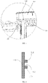
FIG. 9 is a schematic view illustrating a sealing member and a mounting part of a filter assembly added inFIG. 8 . -
FIG. 10 is a partial sectional view taken along line N inFIG. 5 . -
FIG. 11 is a schematic view illustrating a sealing member and a mounting part of a filter assembly added inFIG. 10 . - Reference will now be made in detail to the illustrative embodiments, examples of which are illustrated in the accompanying drawings. When the following description refers to the accompanying drawings, same numerals in different drawings indicate the same or similar elements, unless otherwise indicated. The embodiments described in the following illustrative embodiments do not represent all embodiments consistent with the present disclosure. Rather, they are merely examples of devices consistent with some aspects of the present disclosure as detailed in the appended claims.
- As shown in
FIGS. 1 and 2 , in an air conditioning apparatus in the related art, taking an air conditioner as an example, a ventilation assembly is provided in anindoor unit 100 of the air conditioner, one end of anair input pipe 150 of theindoor unit 100 is communicated with the ventilation assembly, and the other end of theair input pipe 150 is connected with awind shield 160 for guiding an air flow from an outdoor environment into theair input pipe 150. - When the temperature difference between indoor and outdoor is large (for example, the outdoor temperature is lower than -20°C), a cold air flow entering the ventilation assembly may leak out from a gap of the ventilation assembly due to a poor sealing condition of the ventilation assembly in the related art. Warm air in the air conditioning apparatus liquefies when it meets the cold air flow, thereby resulting in condensation. When the condensation is significant, the condensation can form water droplets, which may drip to an indoor floor of a user, and even flow to a wall to form water stains, thus affecting the user experience.
- Referring to
FIGS. 3 and 4 , in an embodiment of the present disclosure, a ventilation assembly is provided, including avolute 110, afilter assembly 170, and asealing member 130. A surface of thevolute 110 is provided with amounting port 111. Thefilter assembly 170 is arranged in themounting port 111 or in a portion of thevolute 110 adjacent to themounting port 111. Thefilter assembly 170 is configured to filter out pollutant particles such as dust or smoke in air flowing through anair channel 115 so as to purify the air. - The sealing
member 130 is positioned at themounting port 111 or at the portion of thevolute 110 adjacent to themounting port 111, and is configured to seal a gap between thefilter assembly 170 and themounting port 111. Or, the sealingmember 130 is located between the filter assembly and the volute, and cooperates with the filter assembly to seal the mounting port. - In the above embodiment, the
sealing member 130 can seal the gap between thefilter assembly 170 and themounting port 111, so as to enhance the sealing performance at themounting port 111, and prevent the air flow entering the volute from the outside from leaking out from the gap between thefilter assembly 170 and thevolute 110 when the ventilation assembly operates, thus greatly reducing the condensation generated when the temperature difference between indoor and outdoor is large, and improving the user experience. - As can be understood, in an example, the ventilation assembly further includes a
fan assembly 140 arranged in thevolute 110 and configured to drive the air to flow by rotation. Themounting port 111 may serve as an air inlet of theair channel 115. In this case, an air input face of thefan assembly 140 facing themounting port 111. Themounting port 111 may also serve as an air outlet of theair channel 115. In this case, an air output face of thefan assembly 140 facing themounting port 111. Or, as shown inFIG. 3 , themounting port 111 may not be the air inlet nor the air outlet, but may be an opening arranged between the air inlet and the air outlet. In this case, the air output face or the air input face of thefan assembly 140 may face themounting port 111. - In some embodiments, the sealing member has a shape substantially the same with a shape of the gap between the filter assembly and the mounting port to seal the gap between the filter assembly and the mounting port.
- In some embodiments, the sealing
member 130 is made of an elastic material such as rubber, plastic, silica gel or the like, and thesealing member 130 of the elastic material can seal the gap at themounting port 111 with the elasticity of the material, which is conducive to improving the sealing effect. - In some embodiments, the
filter assembly 170 includes abracket 120, a part of thebracket 120 adjacent to the mountingport 111 is formed to have a shape substantially the same with that of the mountingport 111 to cover the mountingport 111. The sealing member is arranged between thebracket 120 and thevolute 110 and has a shape substantially the same with a shape of a gap between thebracket 120 and the mountingport 111 so as to form a sealing for the gap between thevolute 110 and thebracket 120 at the mountingport 111. - In some embodiments, an
air channel 115 communicated with the mountingport 111 is provided inside thevolute 110, and thefilter assembly 170 further includes a filter screen mounted to thebracket 120 and arranged in theair channel 115. - The
bracket 120 has a larger mechanical strength than the filter screen, thebracket 120 is configured to support the filter screen, and the filter screen is mounted to thevolute 110 through thebracket 120. - In some embodiments, the filter screen may be arranged entirely within the
air channel 115, and at least part of thebracket 120 is arranged at the mountingport 111 for covering the mountingport 111 and for sealing the mountingport 111 together with the sealingmember 130. - In some embodiments, the part of the
bracket 120 covering the mountingport 111 has a substantially plate-shaped structure, a bottom surface of the plate-shaped structure faces theair channel 115, and the filter screen is in contact with the bottom surface of the plate-shaped structure. - In some embodiments, at least part of the
filter assembly 170 is exposed outside thevolute 110. - In actual applications, after a long-term use, the
filter assembly 170 tends to be clogged due to the accumulation of excessive particulate matters, thereby affecting the filtering effect. Thus, thefilter assembly 170 needs to be periodically cleaned or replaced. Since at least part of thefilter assembly 170 is exposed outside thevolute 110, it is convenient to detach thefilter assembly 170 so as to realize the replacement or cleaning of thefilter assembly 170. - In some embodiments, part of the
bracket 120 of thefilter assembly 170 is exposed outside thevolute 110 and a user may take the filter screen out of the mountingport 111 by detaching thebracket 120. - In some embodiments, the
bracket 120 includes an operating member arranged with a surface facing away from theair channel 115. The operating member may be a tab. Or, as shown inFIG. 2 , the operating member may be aslot 124 formed in thebracket 120, and the user may detach thefilter assembly 170 from the mountingport 111 by pulling the tab or hooking theslot 124. Thus, the arrangement of the operating member facilitates the replacement of thefilter assembly 170. - In some embodiments, a
positioning groove 112 is provided at the mountingport 111 of thevolute 110 along a periphery or an edge of the mountingport 111, and the sealingmember 130 is arranged in thepositioning groove 112. - As shown in
FIGS. 5 to 7 , thepositioning groove 112 surrounds the mountingport 111, thepositioning groove 112 receives the sealingmember 130, and a positioning rib of thepositioning groove 112 supports the sealingmember 130. - In some embodiments, the sealing
member 130 includes a sealing ring. - The sealing ring is substantially annular. Generally, the shape of the sealing
member 130 is substantially the same with the shape of thepositioning groove 112. For example, when thepositioning groove 112 has a square ring shape, the sealingmember 130 also has a square ring shape, and when thepositioning groove 112 has a circular ring shape, and the sealingmember 130 also has a circular ring shape. - In some embodiments, a thickness of the sealing
member 130 is slightly greater than a width of thepositioning groove 112, and the sealingmember 130 is in an interference fit with thepositioning groove 112 so as to be clamped in the positioning groove, thereby ensuring that the sealingmember 130 tends not to get loose after assembling. In some embodiments, the sealingmember 130 and the positioning groove may have an interference fit of 0.1 mm to 0.2 mm. - In some embodiments, a difference between inner and outer radiuses of the sealing
member 130 is slightly greater than a distance between a top and a bottom of the positioning groove 112 (e.g., 0.3 mm) so that the sealingmember 130 is in an interference fit with a mountingpart 121 of thebracket 120 in thefilter assembly 170 so as to realize the sealing at the mountingport 111. - It should be noted that the thickness of the sealing
member 130 is defined in a direction perpendicular to a plane where the sealingmember 130 is, and the inner and outer radiuses of the sealingmember 130 are defined in the plane where the sealingmember 130 is. Accordingly, the width of thepositioning groove 112 is defined in the direction perpendicular to the plane where the sealingmember 130 is, and the distance between the top and the bottom of thepositioning groove 112 is defined in the plane where the sealingmember 130 is and in a direction parallel to a radial direction of the sealingmember 130. That is, the top and the bottom of thepositioning groove 112 are defined in the direction parallel to the radial direction of the sealingmember 130. - Referring to
FIGS. 8 and9 , when the ventilation assembly is assembled, the sealingmember 130 is first placed in thepositioning groove 112, and then thefilter assembly 170 is placed in the mountingport 111. Then, a pressure is applied to thefilter assembly 170, thefilter assembly 170 presses the sealingmember 130, and the sealingmember 130 of the elastic material is deformed after being pressed. Since the difference between the inner radius and the outer radius of the sealingmember 130 is larger than the distance between the top and the bottom of thepositioning groove 112, the sealingmember 130 which is not pressed may protrude out of the top of thepositioning groove 112, and the sealingmember 130 which is pressed to deform may generate a reactive force to the mountingpart 121 of thebracket 120 in thefilter assembly 170, so that the sealingmember 130 and thefilter assembly 170 are tightly fitted with each other, thus realizing the sealing of the mountingport 111. - In some embodiments, the ventilation assembly further includes a fastening structure, and the fastening structure includes a first fastener arranged with the
volute 110 and a second fastener arranged with thefilter assembly 170. The first fastener and the second fastener are engaged after at least part of thefilter assembly 170 is inserted into theair channel 115, so as to prevent thefilter assembly 170 from being separated from thevolute 110. The fastening structure is configured to reinforce the connection of thefilter assembly 170 and thevolute 110 so as to further secure the sealing effect of thefilter assembly 170 and the sealingmember 130 on the mountingport 111. - In some embodiments, the first fastener includes a snap, the second fastener includes a protrusion or a mounting groove, and the snap is engaged with the protrusion or the mounting groove.
- In some embodiments, the
volute 110 is provided with two positioning ribs on a side wall at the mounting port, i.e. afirst positioning rib 114 and asecond positioning rib 113, and the two positioning ribs extend circumferentially along the mountingport 111. Thepositioning groove 112 is formed between thefirst positioning rib 114 and thesecond positioning rib 113. - In some embodiments, the
first positioning rib 114 and thesecond positioning rib 113 have the same size, only referring toFIGS. 8 and9 . - In some embodiments, the
first positioning rib 114 and thesecond positioning rib 113 have different sizes. Specifically, a distance between anend face 300 of thefirst positioning rib 114 facing the mountingport 111 and anend face 400 of thefirst positioning rib 114 connected to thevolute 110 is smaller than the difference between the inner radius and the outer radius of the sealingmember 130, and a distance between anend face 500 of thesecond positioning rib 113 facing the mountingport 111 and anend face 600 of thesecond positioning rib 113 connected to thevolute 110 is larger than the difference between the inner radius and the outer radius of the sealingmember 130, only referring toFIGS. 10 and11 . - In some embodiments, a part of the
first positioning rib 114 and a corresponding part of thesecond positioning rib 113 may have the same size, and another part of thefirst positioning rib 114 and another corresponding part of thesecond positioning rib 113 may have different sizes, referring toFIG. 5 in combination withFIGS. 8-11 . - Referring to
FIGS. 10 and11 , when the sealingmember 130 is arranged in thepositioning groove 112, an upper surface of the sealingmember 130 abuts against thefirst positioning rib 114, and a lower surface of the sealingmember 130 abuts against thesecond positioning rib 113. Since the distance between theend face 500 of thesecond positioning rib 113 facing the mountingport 111 and theend face 600 of thesecond positioning rib 113 connected to thevolute 110 is larger than the difference between the inner radius and the outer radius of the sealingmember 130, thesecond positioning rib 113 has a position limiting function to the sealing member and prevents the sealingmember 130 from inadvertently falling into the volute through the mountingport 111 during mounting. - It should be noted that the upper surface and the lower surface of the sealing
member 130 are defined in the direction perpendicular to the plane where the sealingmember 130 is. - In some embodiments, an
air channel 115 communicating with the mountingport 111 is provided in the volute. Thebracket 120 includes a mountingpart 121 and a supportingpart 122. The mountingpart 121 covers the mountingport 111. The supportingpart 122 is connected with the mountingpart 121 and arranged in theair channel 115, and the filter screen is connected with the mountingpart 121 and/or the supportingpart 122. The sealingmember 130 is arranged in a gap between the mountingpart 121 and thevolute 110. - As shown in
FIG. 4 , the mountingpart 121 has a shape and a size substantially matching with those of the mountingport 111 so as to cover the mountingport 111, and the supportingpart 122 has a shape and a size slightly smaller than those of the mounting port, so that when thefilter assembly 170 is mounted, the supportingpart 122 can pass through the mountingport 111 to be arranged in theair channel 115, and the mountingportion 121 does not pass through the mountingport 111 to enter theair channel 115, but is stuck at the mountingport 111. The mountingpart 121 may be a plate-shaped structure. - The supporting
part 122 arranged in theair channel 115 can better support the filter screen arranged with the supportingpart 122, so that the problems of deformation of the filter screen or the like caused by a high air flowing speed in theair channel 115 are reduced. - As shown in
FIG. 4 , the supportingpart 122 is a rectangular frame. In some embodiments, the supportingpart 122 may also have a T shape, a grid shape, an arch shape, a closed or unclosed ring shape, etc. - In some embodiments, the supporting
part 122 and the mountingpart 121 together form a mountingopening 123, and the filter screen is arranged in the mountingopening 123. - In some embodiments, as shown in
FIG. 4 , the supportingpart 122 and the mountingpart 121 together form a closed annular structure, the filter screen has a shape substantially the same with a shape of the annular structure, and a cross-sectional area of the filter screen is greater than or equal to a cross-sectional area of the annular structure to ensure that the filter screen completely covers the mountingopening 123 to ensure the filtering effect. - In some embodiments, the
filter assembly 170 is arranged transversely in theair channel 115. - The
filter assembly 170 transversely arranged in theair channel 115 can be in contact with the air flow in the largest area, so that the filtering effect is guaranteed. - In some embodiments, in order to further ensure the filtering effect of the
filter assembly 170, a sectional area of thefilter assembly 170 is greater than or equal to a sectional area of theair channel 115. - In some embodiments of the present disclosure, the ventilation assembly further includes a
fan assembly 140 arranged in thevolute 110, and an air output surface of thefan assembly 140 is communicated with theair channel 115. - The present disclosure also provides an air conditioning apparatus including the ventilation assembly according to any one of the above embodiments. The air conditioning apparatus may be a fresh air ventilator, an air purifier, an air conditioner or an air humidity conditioning apparatus, etc.
- The beneficial effects of the present disclosure can be verified by a following simulation experiment, and the simulation experiment has a general process: the
volute 110 is placed on an experimental table, a fan is added at the mountingport 111 of theair channel 115 to blow against the mountingport 111, and after a period of time, the condensation generation of an indoor unit arranged indoors of the air conditioning apparatus is observed. As can be seen from a result of the experiment, the improvement effect of the condensation at the mountingport 111 is significant in this example, compared with thevolute 110 which is not provided with the sealingmember 130. - The features disclosed in the product embodiments provided by the present disclosure may be combined arbitrarily to obtain a new product embodiment without conflict.
- Other embodiments of the disclosure will be apparent to those skilled in the art from consideration of the specification and practice of the disclosure. This disclosure is intended to cover any variations, uses, or adaptations of the present disclosure following the general principles of the present disclosure and including common general knowledge or customary technical means in the art not disclosed in the present disclosure.
Claims (15)
- A ventilation assembly, comprising:a volute (110), a surface of the volute (110) being provided with a mounting port (111);a filter assembly (170) arranged in the mounting port (111) or in a portion of the volute (110) adjacent to the mounting port (111), and configured to filter air; anda sealing member (130) arranged with the mounting port (111) or with the portion of the volute (110) adjacent to the mounting port (111), and configured to seal a gap between the filter assembly (170) and the mounting port (111).
- The ventilation assembly according to claim 1, wherein the sealing member (130) has a shape substantially the same with a shape of the gap between the filter assembly (170) and the mounting port (111).
- The ventilation assembly according to claim 1 or 2, wherein the filter assembly (170) comprises a bracket (120), a part of the bracket (120) adjacent to the mounting port (111) is configured to have a shape substantially the same with a shape of the mounting port (111) to cover the mounting port (111);
the sealing member (130) is arranged between the bracket (120) and the volute (110) and has a shape substantially the same with a shape of a gap between the bracket (120) and the mounting port (111). - The ventilation assembly according to any one of claims 1 to 3, wherein a positioning groove (112) is provided at the mounting port (111) of the volute (110) along a periphery of the mounting port (111), and the sealing member (130) is arranged in the positioning groove (112).
- The ventilation assembly according to claim 4, wherein a thickness of the sealing member (130) is slightly larger than a width of the positioning groove (112), so that the sealing member (130) is clamped in the positioning groove (112) through an interference fit with the positioning groove (112).
- The ventilation assembly according to claim 4 or 5, wherein a difference between inner and outer radiuses of the sealing member (130) is slightly greater than a distance between a top and a bottom of the positioning groove (112), so that the sealing member (130) is in an interference fit with the filter assembly (170).
- The ventilation assembly according to any one of claims 4 to 6, wherein a first positioning rib (114) and a second positioning rib (113) are arranged at the mounting port (111) of the volute (110), and the positioning groove (112) is formed between the first positioning rib (114) and the second positioning rib (113).
- The ventilation assembly according to claim 7, wherein a distance between an end face of the first positioning rib (114) facing the mounting port (111) and an end face of the first positioning rib (114) connected to the volute (110) is smaller than a difference between inner and outer radiuses of the sealing member (130);
a distance between an end face of the second positioning rib (113) facing the mounting port (111) and an end face of the second positioning rib (113) connected to the volute (110) is larger than the difference between the inner and outer radiuses of the sealing member (130). - The ventilation assembly according to claim 3, wherein an air channel (115) communicated with the mounting port (111) is arranged in the volute (110),
the bracket (120) comprises:a mounting part (121) having a shape substantially the same with the shape of the mounting port (111) to cover the mounting port (111); anda supporting part (122) connected with the mounting part (121), arranged in the air channel (115) and configured to support a filter screen connected with the supporting part (122),the sealing member (130) is arranged between the mounting part (121) and the volute (110). - The ventilation assembly according to claim 9, wherein the bracket (120) further comprises an operating member arranged with a surface facing away from the air channel (115).
- The ventilation assembly according to claim 9 or 10, wherein the filter assembly (170) is arranged transversely in the air channel (115), and a sectional area of the filter assembly (170) is greater than or equal to a sectional area of the air channel (115).
- The ventilation assembly according to any one of claims 9 to 11, further comprising a fan assembly (140) arranged in the volute (110) and configured to drive air to flow by rotation, and the fan assembly (140) having an air output surface communicated with the air channel (115).
- The ventilation assembly according to any one of claims 1 to 12, further comprising a fastening structure, wherein the fastening structure comprises a first fastener arranged with the volute (110) and a second fastener arranged with the filter assembly (170), and the first fastener and the second fastener are engaged with each other to prevent the filter assembly (170) from being separated from the volute (110).
- The ventilation assembly according to claim 13, wherein the first fastener comprises a snap, the second fastener comprises a protrusion or a mounting groove, and the snap is engaged with the protrusion or the mounting groove.
- An air conditioning apparatus, comprising a ventilation assembly according to any one of claims 1 to 14.
Applications Claiming Priority (1)
| Application Number | Priority Date | Filing Date | Title |
|---|---|---|---|
| CN202120198593.2U CN214249952U (en) | 2021-01-25 | 2021-01-25 | Ventilation assembly and air conditioning equipment |
Publications (2)
| Publication Number | Publication Date |
|---|---|
| EP4033167A1 true EP4033167A1 (en) | 2022-07-27 |
| EP4033167B1 EP4033167B1 (en) | 2025-08-13 |
Family
ID=76708008
Family Applications (1)
| Application Number | Title | Priority Date | Filing Date |
|---|---|---|---|
| EP21182293.7A Active EP4033167B1 (en) | 2021-01-25 | 2021-06-29 | Ventilation assembly and air conditioning apparatus |
Country Status (5)
| Country | Link |
|---|---|
| US (1) | US11786854B2 (en) |
| EP (1) | EP4033167B1 (en) |
| CN (1) | CN214249952U (en) |
| DE (1) | DE202021103965U1 (en) |
| ES (1) | ES3040573T3 (en) |
Citations (6)
| Publication number | Priority date | Publication date | Assignee | Title |
|---|---|---|---|---|
| FR2815699A1 (en) * | 2000-10-20 | 2002-04-26 | Valeo | Filtration device for automobile air conditioning comprises plastic frame, enclosing filtering medium, with flexible strip surrounding partition to ensure sealing |
| EP1254796A1 (en) * | 2001-04-30 | 2002-11-06 | Valeo | Filtration device for an apparatus for ventilating and/or heating and/or air conditioning, especially for a motor vehicle and the apparatus with such a device |
| EP1306120A1 (en) * | 2001-10-29 | 2003-05-02 | Valeo Matériaux de Friction | Air filter and air circulation system for a motor vehicle comprising the air filter |
| FR2896016A1 (en) * | 2006-01-10 | 2007-07-13 | Mann & Hummel Gmbh | AIR FILTER FOR MOTOR VEHICLE |
| CN108386927A (en) * | 2018-02-12 | 2018-08-10 | 彭志军 | A kind of integrated intelligence furniture cabinet |
| EP3734172A1 (en) * | 2019-03-03 | 2020-11-04 | GD Midea Air-Conditioning Equipment Co., Ltd. | Fresh air module and air conditioner |
Family Cites Families (2)
| Publication number | Priority date | Publication date | Assignee | Title |
|---|---|---|---|---|
| US20110277442A1 (en) * | 2010-05-12 | 2011-11-17 | General Electric Company | Seal for Gas Turbine Filter |
| CN210399176U (en) * | 2019-08-22 | 2020-04-24 | 海信(山东)空调有限公司 | Vertical cabinet type air conditioner |
-
2021
- 2021-01-25 CN CN202120198593.2U patent/CN214249952U/en active Active
- 2021-06-28 US US17/360,952 patent/US11786854B2/en active Active
- 2021-06-29 EP EP21182293.7A patent/EP4033167B1/en active Active
- 2021-06-29 ES ES21182293T patent/ES3040573T3/en active Active
- 2021-07-26 DE DE202021103965.5U patent/DE202021103965U1/en active Active
Patent Citations (6)
| Publication number | Priority date | Publication date | Assignee | Title |
|---|---|---|---|---|
| FR2815699A1 (en) * | 2000-10-20 | 2002-04-26 | Valeo | Filtration device for automobile air conditioning comprises plastic frame, enclosing filtering medium, with flexible strip surrounding partition to ensure sealing |
| EP1254796A1 (en) * | 2001-04-30 | 2002-11-06 | Valeo | Filtration device for an apparatus for ventilating and/or heating and/or air conditioning, especially for a motor vehicle and the apparatus with such a device |
| EP1306120A1 (en) * | 2001-10-29 | 2003-05-02 | Valeo Matériaux de Friction | Air filter and air circulation system for a motor vehicle comprising the air filter |
| FR2896016A1 (en) * | 2006-01-10 | 2007-07-13 | Mann & Hummel Gmbh | AIR FILTER FOR MOTOR VEHICLE |
| CN108386927A (en) * | 2018-02-12 | 2018-08-10 | 彭志军 | A kind of integrated intelligence furniture cabinet |
| EP3734172A1 (en) * | 2019-03-03 | 2020-11-04 | GD Midea Air-Conditioning Equipment Co., Ltd. | Fresh air module and air conditioner |
Also Published As
| Publication number | Publication date |
|---|---|
| US11786854B2 (en) | 2023-10-17 |
| CN214249952U (en) | 2021-09-21 |
| EP4033167B1 (en) | 2025-08-13 |
| DE202021103965U1 (en) | 2021-08-03 |
| ES3040573T3 (en) | 2025-11-03 |
| US20220233985A1 (en) | 2022-07-28 |
Similar Documents
| Publication | Publication Date | Title |
|---|---|---|
| CN209672458U (en) | Air conditioner indoor unit and air conditioner | |
| US11845031B2 (en) | Filter assembly, ventilation assembly and air-conditioning apparatus | |
| CN111306633A (en) | Fresh air module and air conditioner | |
| CN108571807B (en) | Piping assembly of air conditioner and air conditioner | |
| WO2022257744A1 (en) | Air conditioner | |
| CN111306631A (en) | Fresh air module and air conditioner | |
| US11786854B2 (en) | Ventilation assembly and air conditioning apparatus | |
| JP6532658B2 (en) | Indoor unit and air conditioner | |
| CN115451497B (en) | Filters and air conditioners | |
| CN111306632B (en) | Fresh air module and air conditioner | |
| CN212132678U (en) | Fresh air module and air conditioner | |
| CN215637917U (en) | Casing assembly, air conditioner indoor unit and air conditioner | |
| CN212132677U (en) | Fresh air module and air conditioner | |
| CN216143831U (en) | Machine and air conditioner in new trend module, air conditioning | |
| CN211854211U (en) | Fresh air module and air conditioner | |
| CN210164670U (en) | Centrifugal scavenger fan | |
| CN106679147B (en) | Air conditioner | |
| CN218269319U (en) | Purification module, filtering component and air conditioner | |
| JP3293238B2 (en) | Air conditioning ventilation fan | |
| CN215566864U (en) | Panel assembly of ventilator device and ventilator device | |
| CN107345686B (en) | Air treatment module and air conditioner | |
| CN111306634B (en) | Fresh air module and air conditioner | |
| CN219775879U (en) | Air treatment unit | |
| CN219454092U (en) | Wall-hanging type air conditioner indoor unit | |
| CN221570762U (en) | Pipe orifice protection structure and air conditioning equipment |
Legal Events
| Date | Code | Title | Description |
|---|---|---|---|
| PUAI | Public reference made under article 153(3) epc to a published international application that has entered the european phase |
Free format text: ORIGINAL CODE: 0009012 |
|
| STAA | Information on the status of an ep patent application or granted ep patent |
Free format text: STATUS: THE APPLICATION HAS BEEN PUBLISHED |
|
| AK | Designated contracting states |
Kind code of ref document: A1 Designated state(s): AL AT BE BG CH CY CZ DE DK EE ES FI FR GB GR HR HU IE IS IT LI LT LU LV MC MK MT NL NO PL PT RO RS SE SI SK SM TR |
|
| STAA | Information on the status of an ep patent application or granted ep patent |
Free format text: STATUS: REQUEST FOR EXAMINATION WAS MADE |
|
| 17P | Request for examination filed |
Effective date: 20230123 |
|
| RBV | Designated contracting states (corrected) |
Designated state(s): AL AT BE BG CH CY CZ DE DK EE ES FI FR GB GR HR HU IE IS IT LI LT LU LV MC MK MT NL NO PL PT RO RS SE SI SK SM TR |
|
| STAA | Information on the status of an ep patent application or granted ep patent |
Free format text: STATUS: EXAMINATION IS IN PROGRESS |
|
| 17Q | First examination report despatched |
Effective date: 20241106 |
|
| GRAP | Despatch of communication of intention to grant a patent |
Free format text: ORIGINAL CODE: EPIDOSNIGR1 |
|
| STAA | Information on the status of an ep patent application or granted ep patent |
Free format text: STATUS: GRANT OF PATENT IS INTENDED |
|
| INTG | Intention to grant announced |
Effective date: 20250328 |
|
| P01 | Opt-out of the competence of the unified patent court (upc) registered |
Free format text: CASE NUMBER: APP_24977/2025 Effective date: 20250526 |
|
| GRAS | Grant fee paid |
Free format text: ORIGINAL CODE: EPIDOSNIGR3 |
|
| GRAA | (expected) grant |
Free format text: ORIGINAL CODE: 0009210 |
|
| STAA | Information on the status of an ep patent application or granted ep patent |
Free format text: STATUS: THE PATENT HAS BEEN GRANTED |
|
| AK | Designated contracting states |
Kind code of ref document: B1 Designated state(s): AL AT BE BG CH CY CZ DE DK EE ES FI FR GB GR HR HU IE IS IT LI LT LU LV MC MK MT NL NO PL PT RO RS SE SI SK SM TR |
|
| REG | Reference to a national code |
Ref country code: GB Ref legal event code: FG4D |
|
| REG | Reference to a national code |
Ref country code: CH Ref legal event code: EP |
|
| REG | Reference to a national code |
Ref country code: DE Ref legal event code: R096 Ref document number: 602021035976 Country of ref document: DE |
|
| REG | Reference to a national code |
Ref country code: IE Ref legal event code: FG4D |
|
| REG | Reference to a national code |
Ref country code: NL Ref legal event code: FP |
|
| REG | Reference to a national code |
Ref country code: ES Ref legal event code: FG2A Ref document number: 3040573 Country of ref document: ES Kind code of ref document: T3 Effective date: 20251103 |
|
| PG25 | Lapsed in a contracting state [announced via postgrant information from national office to epo] |
Ref country code: IS Free format text: LAPSE BECAUSE OF FAILURE TO SUBMIT A TRANSLATION OF THE DESCRIPTION OR TO PAY THE FEE WITHIN THE PRESCRIBED TIME-LIMIT Effective date: 20251213 |
|
| PG25 | Lapsed in a contracting state [announced via postgrant information from national office to epo] |
Ref country code: NO Free format text: LAPSE BECAUSE OF FAILURE TO SUBMIT A TRANSLATION OF THE DESCRIPTION OR TO PAY THE FEE WITHIN THE PRESCRIBED TIME-LIMIT Effective date: 20251113 |
|
| REG | Reference to a national code |
Ref country code: LT Ref legal event code: MG9D |
|
| PG25 | Lapsed in a contracting state [announced via postgrant information from national office to epo] |
Ref country code: PT Free format text: LAPSE BECAUSE OF FAILURE TO SUBMIT A TRANSLATION OF THE DESCRIPTION OR TO PAY THE FEE WITHIN THE PRESCRIBED TIME-LIMIT Effective date: 20251215 |
|
| PG25 | Lapsed in a contracting state [announced via postgrant information from national office to epo] |
Ref country code: FI Free format text: LAPSE BECAUSE OF FAILURE TO SUBMIT A TRANSLATION OF THE DESCRIPTION OR TO PAY THE FEE WITHIN THE PRESCRIBED TIME-LIMIT Effective date: 20250813 |
|
| PG25 | Lapsed in a contracting state [announced via postgrant information from national office to epo] |
Ref country code: HR Free format text: LAPSE BECAUSE OF FAILURE TO SUBMIT A TRANSLATION OF THE DESCRIPTION OR TO PAY THE FEE WITHIN THE PRESCRIBED TIME-LIMIT Effective date: 20250813 |
|
| PG25 | Lapsed in a contracting state [announced via postgrant information from national office to epo] |
Ref country code: GR Free format text: LAPSE BECAUSE OF FAILURE TO SUBMIT A TRANSLATION OF THE DESCRIPTION OR TO PAY THE FEE WITHIN THE PRESCRIBED TIME-LIMIT Effective date: 20251114 |
|
| PG25 | Lapsed in a contracting state [announced via postgrant information from national office to epo] |
Ref country code: SE Free format text: LAPSE BECAUSE OF FAILURE TO SUBMIT A TRANSLATION OF THE DESCRIPTION OR TO PAY THE FEE WITHIN THE PRESCRIBED TIME-LIMIT Effective date: 20250813 |
|
| PG25 | Lapsed in a contracting state [announced via postgrant information from national office to epo] |
Ref country code: LV Free format text: LAPSE BECAUSE OF FAILURE TO SUBMIT A TRANSLATION OF THE DESCRIPTION OR TO PAY THE FEE WITHIN THE PRESCRIBED TIME-LIMIT Effective date: 20250813 |
|
| PG25 | Lapsed in a contracting state [announced via postgrant information from national office to epo] |
Ref country code: PL Free format text: LAPSE BECAUSE OF FAILURE TO SUBMIT A TRANSLATION OF THE DESCRIPTION OR TO PAY THE FEE WITHIN THE PRESCRIBED TIME-LIMIT Effective date: 20250813 Ref country code: BG Free format text: LAPSE BECAUSE OF FAILURE TO SUBMIT A TRANSLATION OF THE DESCRIPTION OR TO PAY THE FEE WITHIN THE PRESCRIBED TIME-LIMIT Effective date: 20250813 |
|
| PG25 | Lapsed in a contracting state [announced via postgrant information from national office to epo] |
Ref country code: RS Free format text: LAPSE BECAUSE OF FAILURE TO SUBMIT A TRANSLATION OF THE DESCRIPTION OR TO PAY THE FEE WITHIN THE PRESCRIBED TIME-LIMIT Effective date: 20251113 |
|
| REG | Reference to a national code |
Ref country code: AT Ref legal event code: MK05 Ref document number: 1825009 Country of ref document: AT Kind code of ref document: T Effective date: 20250813 |
|
| PG25 | Lapsed in a contracting state [announced via postgrant information from national office to epo] |
Ref country code: SM Free format text: LAPSE BECAUSE OF FAILURE TO SUBMIT A TRANSLATION OF THE DESCRIPTION OR TO PAY THE FEE WITHIN THE PRESCRIBED TIME-LIMIT Effective date: 20250813 |
|
| PG25 | Lapsed in a contracting state [announced via postgrant information from national office to epo] |
Ref country code: DK Free format text: LAPSE BECAUSE OF FAILURE TO SUBMIT A TRANSLATION OF THE DESCRIPTION OR TO PAY THE FEE WITHIN THE PRESCRIBED TIME-LIMIT Effective date: 20250813 |
|
| PG25 | Lapsed in a contracting state [announced via postgrant information from national office to epo] |
Ref country code: AT Free format text: LAPSE BECAUSE OF FAILURE TO SUBMIT A TRANSLATION OF THE DESCRIPTION OR TO PAY THE FEE WITHIN THE PRESCRIBED TIME-LIMIT Effective date: 20250813 |
|
| PG25 | Lapsed in a contracting state [announced via postgrant information from national office to epo] |
Ref country code: IT Free format text: LAPSE BECAUSE OF FAILURE TO SUBMIT A TRANSLATION OF THE DESCRIPTION OR TO PAY THE FEE WITHIN THE PRESCRIBED TIME-LIMIT Effective date: 20250813 |
|
| PG25 | Lapsed in a contracting state [announced via postgrant information from national office to epo] |
Ref country code: CZ Free format text: LAPSE BECAUSE OF FAILURE TO SUBMIT A TRANSLATION OF THE DESCRIPTION OR TO PAY THE FEE WITHIN THE PRESCRIBED TIME-LIMIT Effective date: 20250813 |
|
| PG25 | Lapsed in a contracting state [announced via postgrant information from national office to epo] |
Ref country code: EE Free format text: LAPSE BECAUSE OF FAILURE TO SUBMIT A TRANSLATION OF THE DESCRIPTION OR TO PAY THE FEE WITHIN THE PRESCRIBED TIME-LIMIT Effective date: 20250813 Ref country code: SK Free format text: LAPSE BECAUSE OF FAILURE TO SUBMIT A TRANSLATION OF THE DESCRIPTION OR TO PAY THE FEE WITHIN THE PRESCRIBED TIME-LIMIT Effective date: 20250813 |