EP4033148B1 - Method and controller for operating a gas burner appliance - Google Patents
Method and controller for operating a gas burner appliance Download PDFInfo
- Publication number
- EP4033148B1 EP4033148B1 EP21153258.5A EP21153258A EP4033148B1 EP 4033148 B1 EP4033148 B1 EP 4033148B1 EP 21153258 A EP21153258 A EP 21153258A EP 4033148 B1 EP4033148 B1 EP 4033148B1
- Authority
- EP
- European Patent Office
- Prior art keywords
- gas
- air
- flow
- fan
- air mixture
- Prior art date
- Legal status (The legal status is an assumption and is not a legal conclusion. Google has not performed a legal analysis and makes no representation as to the accuracy of the status listed.)
- Active
Links
Images

Classifications
-
- F—MECHANICAL ENGINEERING; LIGHTING; HEATING; WEAPONS; BLASTING
- F23—COMBUSTION APPARATUS; COMBUSTION PROCESSES
- F23N—REGULATING OR CONTROLLING COMBUSTION
- F23N1/00—Regulating fuel supply
- F23N1/02—Regulating fuel supply conjointly with air supply
- F23N1/022—Regulating fuel supply conjointly with air supply using electronic means
-
- F—MECHANICAL ENGINEERING; LIGHTING; HEATING; WEAPONS; BLASTING
- F23—COMBUSTION APPARATUS; COMBUSTION PROCESSES
- F23D—BURNERS
- F23D14/00—Burners for combustion of a gas, e.g. of a gas stored under pressure as a liquid
- F23D14/46—Details
- F23D14/60—Devices for simultaneous control of gas and combustion air
-
- F—MECHANICAL ENGINEERING; LIGHTING; HEATING; WEAPONS; BLASTING
- F23—COMBUSTION APPARATUS; COMBUSTION PROCESSES
- F23N—REGULATING OR CONTROLLING COMBUSTION
- F23N1/00—Regulating fuel supply
- F23N1/02—Regulating fuel supply conjointly with air supply
- F23N1/025—Regulating fuel supply conjointly with air supply using electrical or electromechanical means
-
- F—MECHANICAL ENGINEERING; LIGHTING; HEATING; WEAPONS; BLASTING
- F23—COMBUSTION APPARATUS; COMBUSTION PROCESSES
- F23N—REGULATING OR CONTROLLING COMBUSTION
- F23N5/00—Systems for controlling combustion
- F23N5/02—Systems for controlling combustion using devices responsive to thermal changes or to thermal expansion of a medium
- F23N5/12—Systems for controlling combustion using devices responsive to thermal changes or to thermal expansion of a medium using ionisation-sensitive elements, i.e. flame rods
- F23N5/126—Systems for controlling combustion using devices responsive to thermal changes or to thermal expansion of a medium using ionisation-sensitive elements, i.e. flame rods using electrical or electromechanical means
-
- F—MECHANICAL ENGINEERING; LIGHTING; HEATING; WEAPONS; BLASTING
- F23—COMBUSTION APPARATUS; COMBUSTION PROCESSES
- F23N—REGULATING OR CONTROLLING COMBUSTION
- F23N5/00—Systems for controlling combustion
- F23N5/18—Systems for controlling combustion using detectors sensitive to rate of flow of air or fuel
- F23N5/184—Systems for controlling combustion using detectors sensitive to rate of flow of air or fuel using electronic means
-
- F—MECHANICAL ENGINEERING; LIGHTING; HEATING; WEAPONS; BLASTING
- F23—COMBUSTION APPARATUS; COMBUSTION PROCESSES
- F23K—FEEDING FUEL TO COMBUSTION APPARATUS
- F23K2900/00—Special features of, or arrangements for fuel supplies
- F23K2900/05001—Control or safety devices in gaseous or liquid fuel supply lines
-
- F—MECHANICAL ENGINEERING; LIGHTING; HEATING; WEAPONS; BLASTING
- F23—COMBUSTION APPARATUS; COMBUSTION PROCESSES
- F23N—REGULATING OR CONTROLLING COMBUSTION
- F23N5/00—Systems for controlling combustion
- F23N5/18—Systems for controlling combustion using detectors sensitive to rate of flow of air or fuel
- F23N2005/181—Systems for controlling combustion using detectors sensitive to rate of flow of air or fuel using detectors sensitive to rate of flow of air
-
- F—MECHANICAL ENGINEERING; LIGHTING; HEATING; WEAPONS; BLASTING
- F23—COMBUSTION APPARATUS; COMBUSTION PROCESSES
- F23N—REGULATING OR CONTROLLING COMBUSTION
- F23N5/00—Systems for controlling combustion
- F23N5/18—Systems for controlling combustion using detectors sensitive to rate of flow of air or fuel
- F23N2005/185—Systems for controlling combustion using detectors sensitive to rate of flow of air or fuel using detectors sensitive to rate of flow of fuel
-
- F—MECHANICAL ENGINEERING; LIGHTING; HEATING; WEAPONS; BLASTING
- F23—COMBUSTION APPARATUS; COMBUSTION PROCESSES
- F23N—REGULATING OR CONTROLLING COMBUSTION
- F23N2221/00—Pretreatment or prehandling
- F23N2221/10—Analysing fuel properties, e.g. density, calorific
-
- F—MECHANICAL ENGINEERING; LIGHTING; HEATING; WEAPONS; BLASTING
- F23—COMBUSTION APPARATUS; COMBUSTION PROCESSES
- F23N—REGULATING OR CONTROLLING COMBUSTION
- F23N2225/00—Measuring
- F23N2225/04—Measuring pressure
-
- F—MECHANICAL ENGINEERING; LIGHTING; HEATING; WEAPONS; BLASTING
- F23—COMBUSTION APPARATUS; COMBUSTION PROCESSES
- F23N—REGULATING OR CONTROLLING COMBUSTION
- F23N2225/00—Measuring
- F23N2225/04—Measuring pressure
- F23N2225/06—Measuring pressure for determining flow
-
- F—MECHANICAL ENGINEERING; LIGHTING; HEATING; WEAPONS; BLASTING
- F23—COMBUSTION APPARATUS; COMBUSTION PROCESSES
- F23N—REGULATING OR CONTROLLING COMBUSTION
- F23N2227/00—Ignition or checking
- F23N2227/02—Starting or ignition cycles
-
- F—MECHANICAL ENGINEERING; LIGHTING; HEATING; WEAPONS; BLASTING
- F23—COMBUSTION APPARATUS; COMBUSTION PROCESSES
- F23N—REGULATING OR CONTROLLING COMBUSTION
- F23N2227/00—Ignition or checking
- F23N2227/20—Calibrating devices
-
- F—MECHANICAL ENGINEERING; LIGHTING; HEATING; WEAPONS; BLASTING
- F23—COMBUSTION APPARATUS; COMBUSTION PROCESSES
- F23N—REGULATING OR CONTROLLING COMBUSTION
- F23N2233/00—Ventilators
-
- F—MECHANICAL ENGINEERING; LIGHTING; HEATING; WEAPONS; BLASTING
- F23—COMBUSTION APPARATUS; COMBUSTION PROCESSES
- F23N—REGULATING OR CONTROLLING COMBUSTION
- F23N2233/00—Ventilators
- F23N2233/06—Ventilators at the air intake
- F23N2233/08—Ventilators at the air intake with variable speed
-
- F—MECHANICAL ENGINEERING; LIGHTING; HEATING; WEAPONS; BLASTING
- F23—COMBUSTION APPARATUS; COMBUSTION PROCESSES
- F23N—REGULATING OR CONTROLLING COMBUSTION
- F23N2235/00—Valves, nozzles or pumps
- F23N2235/12—Fuel valves
- F23N2235/16—Fuel valves variable flow or proportional valves
Definitions
- the invention relates to a method for operating a gas burner appliance. Further on, the invention relates to a gas burner appliance
- EP 2 667 097 A1 discloses a method for operating a gas burner appliance.
- a gas/air mixture having a defined mixing ratio of gas and air is provided to a burner for combusting the gas/air mixture.
- the mixing ratio of gas and air of the gas/air mixture corresponds to the so-called ⁇ -value of the gas/air mixture.
- the gas/air mixture is provided by a mixing device mixing an air flow provided by an air duct with a gas flow provided by a gas duct.
- the mixing device may be provided by a Venturi nozzle.
- the air flow flowing through the air duct is provided by a fan in such a way that the fan speed of the fan depends on a nominal burner-load of the gas burner appliance, wherein a fan speed range of the fan defines a so-called modulation range of the gas burner appliance.
- a pneumatic gas regulation valve is provided by a gas armature.
- the gas armature comprises a safety gas valve and a throttle used for calibration.
- the pneumatic gas regulation valve uses a pressure difference between the gas pressure of the gas flow in the gas duct and a reference pressure, wherein either the air pressure of the air flow in the air duct or the ambient pressure is used as reference pressure, and wherein the pressure difference between the gas pressure of the gas flow in the gas duct and the reference pressure is determined and controlled pneumatically.
- EP 2 667 097 A1 discloses a method for operating a gas burner appliance in which the defined mixing ratio of the gas/air mixture is kept constant over the entire modulation range of the gas burner. This is done by the pneumatic gas regulation valve establishing a pneumatic control to keep the mixing ratio of gas and air within the gas/air mixture constant.
- pneumatic gas regulation valve instead of using pneumatic gas regulation valve, it is also known from prior art to control the mixing ratio of gas and air within the gas/air mixture by an electric gas flow modulator.
- the invention relates to a gas burner control making use of such an electric gas flow modulator.
- DE 198 24 521 A1 discloses a method to control the mixing ratio of gas and air of the gas/air mixture and thereby the ⁇ -value of the gas/air mixture on basis of a signal provided by an electrical or electronic sensor like an anemometer.
- An actual value corresponding to a pressure ratio between a gas pressure in a gas duct and an air pressure in an air duct or corresponding to a pressure ratio between the gas pressure in the gas duct and the air pressure at the reference point is provided by the electrical or electronic sensor, wherein this actual value is compared with a nominal value.
- a control variable for the electric gas flow modulator is generated on basis of the control deviation between the actual value and nominal value, wherein the electric gas flow modulator is adjusted on basis of this control variable to control the defined mixing ratio of gas and air in the gas/air mixture thereby keeping the ⁇ -value of the gas/air mixture constant.
- the amount of the air flow and thereby the amount of the flow of the gas/air mixture having the defined mixing ratio of gas and air provided to the burner chamber depends on the desired burner load.
- the nominal burner-load corresponds to a desired heat demand.
- the nominal burner-load defines the fan speed at which the fan is operated.
- the fan speed range of the fan of the gas burner appliance defines the modulation range of the gas burner appliance.
- a maximum fan speed of the fan defines the maximum burner-load of the gas burner appliance. If a desired heat demand requires maximum burner load, then the fan is operated at maximum fan speed. If a desired heat demand requires burner-load being 50% of the maximum burner load, then the fan is operated at 50% of the maximum fan speed.
- the fan is operated at 20% of the maximum fan speed.
- the mixing ratio of gas and air of the is kept constant.
- the gas burner appliance may be operated with different gases belonging to different gas families.
- the gas may belong to the so-called liquefied gas family or to the so-called natural gas family or to the so-called town gas family. These gas families differ from each other by the so-called Wobbe Index being representative of the calorific value of the gas.
- Wobbe Index being representative of the calorific value of the gas.
- the gas burner appliance is operated to determine the gas family of the gas of the gas/air mixture by the following steps: Before the gas burner appliance becomes started, measuring the ambient air pressure by a sensor positioned between the gas safety valve unit and the gas flow modulator. Said ambient air pressure is measured when the safety valve unit is closed, the gas flow modulator is opened and the fan is stopped.
- the method according to the present invention allows to determine the gas family of the gas to be combusted not requiring a mass flow sensor.
- the method may further comprise the following steps: Measuring the ambient air temperature. Determining on basis of the air volume flow and the ambient air temperature the air mass flow. Measuring the gas temperature. Determining on basis of the gas volume flow and the gas temperature the gas mass flow. This allows a further improved determination of the gas family of the gas to be combusted not requiring a mass flow sensor.
- the method may further comprise the following step: Determining on basis of the gas family of the combusted gas an operating parameter set to control combustion of the gas/air mixture within the combustion chamber of the gas burner appliance. A proper combustion of the gas/air mixture in a gas burner appliance can be ensured on basis of such an operating parameter set.
- the method may further comprise the following steps: Determining on a preliminary basis the preliminary gas family of the gas to be combusted, namely on basis of the gas pressure which is measured when the safety valve unit is opened, when the gas flow modulator is opened and when the fan is running. Determining on basis of the preliminary gas family of the gas to be combusted a preliminary parameter set to start the gas burner appliance. With these method steps the start of the gas burner appliance can be improved.
- the method may further comprise the following steps: Operating the gas burner appliance on basis of the operating parameter set to control the mixing ratio of gas and air or the ⁇ -value of the gas/air mixture at a constant value. Determining the opening of the gas flow modulator or the flow resistance of the gas flow modulator to keep the mixing ratio of gas and air or a ⁇ -value of the gas/air mixture at the constant value. Verifying the previously detected gas family of the combusted gas on basis of said opening of the gas flow modulator or said flow resistance of the gas flow modulator. With these method steps the operation of the gas burner appliance can be further improved ensuring a proper combustion of the gas/air mixture in a gas burner appliance.
- the gas burner appliance according to the present invention is defined in claim 12.
- the present invention relates to a method and a gas burner appliance.
- the invention allows to determine the gas family of gas of a gas/air mixture combusted with the gas burner appliance. Further, the invention allows to operate the gas burner appliance on basis of the determined gas family to ensure a proper combustion.
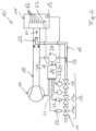
- FIG. 1 shows a schematic view of a first exemplary gas burner appliance 10.
- the gas burner appliance 10 comprises a gas burner chamber 11 in which combustion of a gas/air mixture M having a defined mixing ratio of gas G and air A takes place during burner-on phases of the gas burner appliance 10.
- the mixing ratio of gas G and air A of the gas/air mixture M corresponds to the so-called ⁇ -value of the gas/air mixture M.
- An ignition device 27 is used to ignite the gas/air mixture M for the combustion of the gas/air mixture M within the combustion chamber 11.
- the ignition device 27 of the gas burner appliance 10 is preferably positioned within the combustion chamber 11.
- the ignition device 27 can be activated by a controller 26 of the gas burner appliance 10.
- the combustion of the gas/air mixture results into flames 12.
- the combustion of the gas/air mixture resulting into the flames 12 is monitored by a combustion monitoring device 13.
- the combustion monitoring device 13 is provided by a flame ionization sensor.
- a flame ionization sensor provides as output signal an electrical flame ionization current.
- the combustion monitoring device 13 provides its output signal to the controller 26.
- the gas/air mixture M is provided to the burner chamber 11 of the gas burner appliance 10 by mixing a flow of the air A with a flow of the gas G.
- a fan 14 sucks in air A flowing through an air duct 15 and gas G flowing through a gas duct 16.
- the fan 14 is operated by the controller 26.
- a gas flow modulator 18 for adjusting the gas flow through the gas duct 16 and a safety gas valves unit 19 having preferably two safety gas valves 19a are assigned to the gas duct 16.
- the gas flow modulator 18 and the safety gas valves 19a are part of a gas armature 17 further comprising a sieve 20 and at least one sensor 21.
- the sensor 21 is a pressure and temperature sensor measuring both pressure and temperature. It is possible that the gas armature 17 may comprise separate sensors to measure pressure and temperature. It is also possible that the gas armature 17 may comprise only a pressure sensor.
- the at least one sensor 21 provides its output signal to the controller 26.
- the gas safety valves 19a are operated by electric coils 22 being part of the gas armature 17. In burner-on phases the electric coils 22 are energized by the controller 26 to open the gas safety valves 19a. In burner-off phases the gas safety valves 19a are closed. In Figure 1 , each gas safety valve 19a is operated by one separate electric coil 22. It is possible to operate the gas safety valves 19a by a common electric coil 22.
- the gas flow modulator 18 is operated by a motor 23 also having an electric coil 24.
- the gas flow modulator 18 is an electric gas flow modulator 18 operated by the controller 26.
- the gas/air mixture M having the defined mixing ratio of gas G and air A is provided to the burner chamber 11 of the gas burner appliance 10.
- the gas/air mixture M is provided by mixing the air flow A provided by an air duct 15 with a gas flow G provided by a gas duct 16.
- the air flow and the gas flow become mixed by a mixing device 25.
- the mixing device 25 may be a venturi nozzle.
- the quantity of the air flow A and thereby the quantity of the gas/air mixture flow M is adjusted by the fan 14, namely by the speed of the fan 14.
- the fan speed can be adjusted on basis of a nominal burner-load.
- the fan 14 is operated by the controller 26.
- the fan speed range of the fan 14 defines a modulation range of the gas burner appliance 10.
- a modulation of "1" means that the fan 14 is operated at maximum fan speed (100% of maximum fan speed) and thereby at a full-load of the gas burner appliance 10.
- a modulation of "2" means that the fan 14 is operated at 50% of the maximum fan speed and a modulation of "5" means that the fan 14 is operated at 20% of the maximum fan speed.
- the defined mixing ratio of gas G and air A within the gas/air mixture M and thereby the ⁇ -value of the gas/air mixture M is kept constant.
- Said defined mixing ratio of gas G and air A or said ⁇ -value of the gas/air mixture M is controlled over the modulation range of the gas burner appliance using the electric gas flow modulator 18 of a gas armature 17 in order to keep the defined mixing ratio of gas and air and thereby the ⁇ -value constant over the modulation range of the gas burner appliance 10.
- the control variable for the electric gas flow modulator 18 in order to keep the ⁇ -value constant is generated by the controller 26 on basis of the flame ionization current provided by the combustion monitoring device 13 being the flame ionization sensor.
- Figure 2 shows a schematic view of another exemplary gas burner appliance 10'.
- the constant mixing ratio of gas G and air A within the gas/air mixture M is controlled by the electric gas flow modulator 18 on basis of a signal provided by an electric or electronic pressure sensor 28 and not on basis of the flame ionization current provided by the combustion monitoring device 13 being the flame ionization sensor.
- the electric or electronic sensor 28 may provide to the controller 26 an actual value corresponding to a pressure ratio between a gas pressure in a gas duct 16 and an air pressure in an air duct 15 or corresponding to a pressure ratio between the gas pressure in the gas duct 16 and the air pressure at the reference point.
- the controller 26 may compare said actual value with a nominal value.
- the controller 26 may generate the control variable for the electric gas flow modulator 18 on basis of the control deviation between the actual value and the nominal value, wherein the gas flow modulator 18 may be operated on basis of this control variable to keep over the entire modulation range of the gas burner appliance 10 the defined mixing ratio of gas and air and thereby the ⁇ -value constant.
- the combustion monitoring device 13 may be provided by a photo diode monitoring the presence of the flames 12.
- the method for operating a gas burner appliance allows to determine the gas family of the gas of the gas/air mixture.
- the method comprises the following steps: Before the gas burner appliance 10, 10' becomes started, measuring the ambient air pressure by the pressure and temperature sensor 21.
- Said ambient air pressure is measured when the safety gas valve unit 19 having the at least one gas safety valve 19a is closed, when the gas flow modulator 18 is opened and when the fan 14 is stopped.
- the pressure and temperature sensor 21 may also measure the ambient air temperature when the safety gas valve unit 19 is closed, when the gas flow modulator 18 is opened and when the fan 14 is stopped.
- Measuring the gas pressure by the pressure and temperature sensor 21 Said gas pressure is measured with safety gas valve unit 19 having both safety valves 19a opened, when the gas flow modulator 18 is opened and when the fan 14 is running.
- the pressure and temperature sensor 21 may also measure the gas temperature.
- the pressure and temperature sensor 21 measured the ambient air temperature and the gas temperature, it is possible to determine on basis of the gas volume flow and on basis of the gas temperature the gas mass flow as well as on basis of the air volume flow and on basis of the ambient air temperature the air mass flow. This may be done on basis of a characteristic curve or a characteristic map or a characteristic table implemented within the controller 26.
- the gas family of the combusted gas Determining from the respective ratio between the gas volume flow and the air volume flow or from the respective ratio between the gas mass flow and the air mass flow the gas family of the combusted gas, namely if the combusted gas belongs to the liquefied gas family or the natural gas family or the town gas family. This can also be done on basis of a characteristic curve or a characteristic map or a characteristic table implemented within the controller 26.
- the method according to the invention determines the gas family of the combusted gas. On basis of the determined gas family a proper combustion of the gas/air mixture in a gas burner appliance 10, 10' can be ensured.
- the method comprises the steps: Determining on a preliminary basis from the gas pressure which is measured by the sensor 21 when the safety valve unit 19 is opened, when the gas flow modulator 18 is opened and when the fan 14 is running, a preliminary gas family of the gas to be combusted. Determining on basis of the preliminary gas family of the gas to be combusted a preliminary parameter set to start the gas burner appliance 10, 10'. Such a preliminary parameter set may be implemented within the controller 26. With these method steps the start of the gas burner appliance 10, 10' can be improved.
- the method comprises the steps: Determining on basis of the gas family of the combusted gas an operating parameter set to control combustion of the gas/air mixture within the combustion chamber 11 of the gas burner appliance 10, 10'.
- an operating parameter set may be implemented within the controller 26. A proper combustion of the gas/air mixture in a gas burner appliance 10, 10' can be ensured on basis of such operating parameter set.
- the gas burner appliance 10, 10' may be operated at a defined burner load.
- This defined burner load is preferably at least 50% of the maximum burner load, most preferably at least 75% of the maximum burner load or is at maximum burner load.
- the mixing ratio of gas and air or the ⁇ -value of the gas/air mixture is controlled at a constant value using the operating parameter set.
- the opening of the gas flow modulator 18 or the flow resistance of the gas flow modulator 18 to keep the mixing ratio of gas and air or a ⁇ -value of the gas/air mixture at the constant value is determined.
- the gas family of the combusted gas is verified on basis of said opening of the gas flow modulator 18 or said flow resistance of the gas flow modulator 18. It is for example possible to check if said opening of the gas flow modulator 18 or said flow resistance of the gas flow modulator 18 together with the ambient air pressure and the gas pressure matches with corresponding values for the respective gas family. If this is the case, the determined gas family is found to be correct with the verification. If this is not the case, the determined gas family is found to be incorrect with the verification. If the gas family is found to be incorrect, the method to determine the gas family is repeated.
- the mixing ratio of gas and air or said ⁇ -value is controlled over the modulation range of the gas burner appliance 10, 10' using the electric gas flow modulator 18 of the gas burner appliance 10, 10'.
- the electric gas flow modulator 18 controls said defined mixing ratio of gas and air or said ⁇ -value of the gas/air mixture in such a way that a flame ionization current is measured by the combustion monitoring device 13, and that a control variable for the electric gas flow modulator 18 is generated on basis of the flame ionization current.
- the pressure difference between the gas pressure and the air pressure is measured by an electric or electronic sensor 28 of the gas burner appliance 10', and a control variable for the electric gas flow modulator 18 is generated on basis of the output signal provided by the electric or electronic sensor 28.
- the electric gas flow modulator 18 of the gas armature 17 is operated by energizing the electric coil 24 of the gas armature 17.
- the at least one safety gas valve 19a of the gas armature 17 is operated by energizing the at least one electric coil 22 of the gas armature 17.
- the method may comprise the following steps: Determining at least one electric coil resistance of at least one of the electric coils 22, 24. Determining at least one temperature offset as a function of the at least one electric coil resistance and as a function of at least one time interval for which the respective electric coil 22, 24 becomes energized. Compensating the measured ambient air temperature and/or compensating the measured gas temperature by the at least one temperature offset thereby providing a compensated ambient air temperature and/or a compensated gas temperature. Determining the air mass flow on basis of the ambient air pressure and on basis of the compensated ambient air temperature and/or determining the gas mass flow on basis of the gas pressure and/or on basis of the compensated gas temperature.
- the electric coil resistance of the respective electric coil 22, 24 is calculated on basis of the electrical current and on basis of the electrical voltage both measured at or across the respective electric coil 22, 24.
- the invention further provides a gas burner appliance 10, 10' with a controller 26.
- the controller 26 is configured to operate the gas burner appliance 10, 10' according to the above described method.
- the controller 26 is configured to determine on basis of a heat demand a nominal burner-load to provide the heat demand, wherein the nominal burner-load is a load within a modulation range of the gas burner appliance 10, 10'.
- the controller 26 is further configured determine on basis of the nominal burner-load the fan speed of the fan 14 of the gas burner appliance 10, 10' which is needed to provide the burner load, wherein a fan speed range of the fan 14 defines the modulation range of the gas burner appliance 10, 10'.
- the controller 26 is further configured to receive from the sensor 21 the measured ambient air pressure and preferably the measured ambient air temperature, wherein the ambient air pressure and preferably the ambient air temperature is measured when the safety valve unit 19 is closed, when the gas flow modulator 18 is opened and when the fan 14 is stopped, namely before the gas burner appliance 10, 10' becomes started.
- the controller 26 is further configured to receive from the sensor 21 the measured gas pressure and preferably the measured gas temperature, wherein the gas pressure and preferably the measured gas temperature is measured when the safety valve unit 19 is opened, when the gas flow modulator 18 is opened and when the fan 14 is running.
- the controller 26 is further configured to run the fan 14 at a defined fan speed and to increase the opening of the gas flow modulator 18 or to decrease the flow resistance of the gas flow modulator 18 while also activating the ignition device 27, namely when the gas burner appliance 10, 10' becomes started.
- the controller 26 is further configured to receive from the combustion monitoring device 13 a signal indicating that the activation of ignition device 27 results into a combustion of the gas/air mixture.
- the controller 26 is further configured to determine the respective opening of the gas flow modulator 18 or the respective flow resistance of the gas flow modulator 18.
- the controller 26 is further configured to determine from the fan speed of the fan 14 and from the measured ambient air pressure an air volume flow or an air mass flow.
- the controller 26 is further configured to determine from the opening of the gas flow modulator 18 or from the flow resistance of the gas flow modulator 18 at which the combustion started upon activation of the ignition device 27 and from the measured gas pressure a gas volume flow or a gas mass flow.
- the controller 26 is further configured to determine a ratio between the gas volume flow and the air volume flow or a ratio between the gas mass flow and the air mass flow, and to determine from the respective ratio the gas family of the combusted gas, namely if the combusted gas belongs to the liquefied gas family or the natural gas family or the town gas family.
- the controller 26 is further configured to adjust the setting of the gas burner appliance on basis of the determined gas family.
- This setting preferably describes in Fig. 1 the relation between ionization current and ⁇ -value.
Landscapes
- Engineering & Computer Science (AREA)
- Chemical & Material Sciences (AREA)
- Combustion & Propulsion (AREA)
- Mechanical Engineering (AREA)
- General Engineering & Computer Science (AREA)
- Regulation And Control Of Combustion (AREA)
Description
- The invention relates to a method for operating a gas burner appliance. Further on, the invention relates to a gas burner appliance
-
EP 2 667 097 A1 discloses a method for operating a gas burner appliance. During burner-on-phases of the gas burner appliance, a gas/air mixture having a defined mixing ratio of gas and air is provided to a burner for combusting the gas/air mixture. The mixing ratio of gas and air of the gas/air mixture corresponds to the so-called λ-value of the gas/air mixture. The gas/air mixture is provided by a mixing device mixing an air flow provided by an air duct with a gas flow provided by a gas duct. The mixing device may be provided by a Venturi nozzle. The air flow flowing through the air duct is provided by a fan in such a way that the fan speed of the fan depends on a nominal burner-load of the gas burner appliance, wherein a fan speed range of the fan defines a so-called modulation range of the gas burner appliance. According toEP 2 667 097 A1 , the defined mixing ratio of gas and air and thereby the λ-value of the gas/air mixture is kept constant over the entire modulation range of the gas burner appliance by a pneumatic gas regulation valve. The pneumatic gas regulation valve is provided by a gas armature. In addition to the pneumatic gas regulation valve the gas armature comprises a safety gas valve and a throttle used for calibration. The pneumatic gas regulation valve uses a pressure difference between the gas pressure of the gas flow in the gas duct and a reference pressure, wherein either the air pressure of the air flow in the air duct or the ambient pressure is used as reference pressure, and wherein the pressure difference between the gas pressure of the gas flow in the gas duct and the reference pressure is determined and controlled pneumatically.EP 2 667 097 A1 discloses a method for operating a gas burner appliance in which the defined mixing ratio of the gas/air mixture is kept constant over the entire modulation range of the gas burner. This is done by the pneumatic gas regulation valve establishing a pneumatic control to keep the mixing ratio of gas and air within the gas/air mixture constant. - Instead of using pneumatic gas regulation valve, it is also known from prior art to control the mixing ratio of gas and air within the gas/air mixture by an electric gas flow modulator. The invention relates to a gas burner control making use of such an electric gas flow modulator.
-
DE 198 24 521 A1 discloses a method to control the mixing ratio of gas and air of the gas/air mixture and thereby the λ-value of the gas/air mixture on basis of a signal provided by an electrical or electronic sensor like an anemometer. An actual value corresponding to a pressure ratio between a gas pressure in a gas duct and an air pressure in an air duct or corresponding to a pressure ratio between the gas pressure in the gas duct and the air pressure at the reference point is provided by the electrical or electronic sensor, wherein this actual value is compared with a nominal value. A control variable for the electric gas flow modulator is generated on basis of the control deviation between the actual value and nominal value, wherein the electric gas flow modulator is adjusted on basis of this control variable to control the defined mixing ratio of gas and air in the gas/air mixture thereby keeping the λ-value of the gas/air mixture constant. - As mentioned above, the amount of the air flow and thereby the amount of the flow of the gas/air mixture having the defined mixing ratio of gas and air provided to the burner chamber depends on the desired burner load. The nominal burner-load corresponds to a desired heat demand. The nominal burner-load defines the fan speed at which the fan is operated. The fan speed range of the fan of the gas burner appliance defines the modulation range of the gas burner appliance. A maximum fan speed of the fan defines the maximum burner-load of the gas burner appliance. If a desired heat demand requires maximum burner load, then the fan is operated at maximum fan speed. If a desired heat demand requires burner-load being 50% of the maximum burner load, then the fan is operated at 50% of the maximum fan speed. If a desired heat demand requires burner-load being 20% of the maximum burner load, then the fan is operated at 20% of the maximum fan speed. As mentioned above, at any burner load of the gas burner appliance and at any fan sped of the fan the mixing ratio of gas and air of the is kept constant.
- The gas burner appliance may be operated with different gases belonging to different gas families. The gas may belong to the so-called liquefied gas family or to the so-called natural gas family or to the so-called town gas family. These gas families differ from each other by the so-called Wobbe Index being representative of the calorific value of the gas. In order to ensure a proper combustion of the gas/air mixture in a gas burner appliance, it is of importance that the gas family of the gas to be combusted is known. When knowing the gas family of the gas to be combusted, the operation of gas burner appliance can be adapted to the gas family.
- For the time being the operation of a gas burner appliance taking into account the gas family of gas to be combusted requires the use of mass flow sensors. This results into high costs.
-
DE 101 14 901 A1 ,EP 1 370 806 B1 andUS 6 893 152 B2 all disclose methods for operating a gas burner appliance making us of mass flow sensors. Further prior art is known fromDE 10 2006 051 883 A1US 2004 / 062 290 A1 . - There is a desire to operate a gas burner appliance taking into account the gas family of the combusted gas and to determine the gas family of the combusted gas not requiring a mass flow sensor.
- Against this background, a novel method for operating a gas burner appliance is provided.
- With the method according to the present invention the gas burner appliance is operated to determine the gas family of the gas of the gas/air mixture by the following steps:
Before the gas burner appliance becomes started, measuring the ambient air pressure by a sensor positioned between the gas safety valve unit and the gas flow modulator. Said ambient air pressure is measured when the safety valve unit is closed, the gas flow modulator is opened and the fan is stopped. - When the gas burner appliance becomes started, running the fan at a defined fan speed, increasing the opening of the gas flow modulator or decreasing the flow resistance of the gas flow modulator while activating an ignition device trying to ignite the gas/air mixture until the activation of ignition device results into a combustion of the gas/air mixture monitored by a combustion monitoring device.
- Determining from the fan speed of the fan and from the measured ambient air pressure an air volume flow or an air mass flow.
- Measuring the gas pressure by the sensor positioned between the gas safety valve unit and the gas flow modulator. Said gas pressure is measured when the safety valve unit is opened, the gas flow modulator is opened and the fan is running.
- Determining from the opening of the gas flow modulator or from the flow resistance of the gas flow modulator at which the combustion started upon activation of the ignition device and from the measured gas pressure a gas volume flow or a gas mass flow.
- Determining a ratio between the gas volume flow and the air volume flow or a ratio between the gas mass flow and the air mass flow.
- Determining from the respective ratio the gas family of the combusted gas, namely if the combusted gas belongs to the liquefied gas family or the natural gas family or the town gas family.
- The method according to the present invention allows to determine the gas family of the gas to be combusted not requiring a mass flow sensor.
- On basis of the determined gas family a proper combustion of the gas/air mixture in a gas burner appliance can be ensured.
- The method may further comprise the following steps: Measuring the ambient air temperature. Determining on basis of the air volume flow and the ambient air temperature the air mass flow. Measuring the gas temperature. Determining on basis of the gas volume flow and the gas temperature the gas mass flow. This allows a further improved determination of the gas family of the gas to be combusted not requiring a mass flow sensor.
- The method may further comprise the following step: Determining on basis of the gas family of the combusted gas an operating parameter set to control combustion of the gas/air mixture within the combustion chamber of the gas burner appliance. A proper combustion of the gas/air mixture in a gas burner appliance can be ensured on basis of such an operating parameter set.
- The method may further comprise the following steps: Determining on a preliminary basis the preliminary gas family of the gas to be combusted, namely on basis of the gas pressure which is measured when the safety valve unit is opened, when the gas flow modulator is opened and when the fan is running. Determining on basis of the preliminary gas family of the gas to be combusted a preliminary parameter set to start the gas burner appliance. With these method steps the start of the gas burner appliance can be improved.
- The method may further comprise the following steps: Operating the gas burner appliance on basis of the operating parameter set to control the mixing ratio of gas and air or the λ-value of the gas/air mixture at a constant value. Determining the opening of the gas flow modulator or the flow resistance of the gas flow modulator to keep the mixing ratio of gas and air or a λ-value of the gas/air mixture at the constant value. Verifying the previously detected gas family of the combusted gas on basis of said opening of the gas flow modulator or said flow resistance of the gas flow modulator. With these method steps the operation of the gas burner appliance can be further improved ensuring a proper combustion of the gas/air mixture in a gas burner appliance.
- The gas burner appliance according to the present invention is defined in
claim 12. - Preferred developments of the invention are provided by the dependent claims and the description which follows.
- Exemplary embodiments are explained in more detail on the basis of the drawing, in which:
- Figure 1
- shows a first gas burner appliance to be operated by the method of the present invention:
- Figure 2
- shows a second gas burner appliance to be operated by the method of the present invention.
- The present invention relates to a method and a gas burner appliance. The invention allows to determine the gas family of gas of a gas/air mixture combusted with the gas burner appliance. Further, the invention allows to operate the gas burner appliance on basis of the determined gas family to ensure a proper combustion.
-
Figure 1 shows a schematic view of a first exemplarygas burner appliance 10. Thegas burner appliance 10 comprises agas burner chamber 11 in which combustion of a gas/air mixture M having a defined mixing ratio of gas G and air A takes place during burner-on phases of thegas burner appliance 10. The mixing ratio of gas G and air A of the gas/air mixture M corresponds to the so-called λ-value of the gas/air mixture M. - An
ignition device 27 is used to ignite the gas/air mixture M for the combustion of the gas/air mixture M within thecombustion chamber 11. Theignition device 27 of thegas burner appliance 10 is preferably positioned within thecombustion chamber 11. Theignition device 27 can be activated by acontroller 26 of thegas burner appliance 10. - The combustion of the gas/air mixture results into
flames 12. The combustion of the gas/air mixture resulting into theflames 12 is monitored by acombustion monitoring device 13. In the embodiment ofFig. 1 thecombustion monitoring device 13 is provided by a flame ionization sensor. Such a flame ionization sensor provides as output signal an electrical flame ionization current. - The
combustion monitoring device 13 provides its output signal to thecontroller 26. - The gas/air mixture M is provided to the
burner chamber 11 of thegas burner appliance 10 by mixing a flow of the air A with a flow of the gasG. A fan 14 sucks in air A flowing through anair duct 15 and gas G flowing through agas duct 16. Thefan 14 is operated by thecontroller 26. - A
gas flow modulator 18 for adjusting the gas flow through thegas duct 16 and a safetygas valves unit 19 having preferably twosafety gas valves 19a are assigned to thegas duct 16. Thegas flow modulator 18 and thesafety gas valves 19a are part of agas armature 17 further comprising asieve 20 and at least onesensor 21. - In
Figure 1 thesensor 21 is a pressure and temperature sensor measuring both pressure and temperature. It is possible that thegas armature 17 may comprise separate sensors to measure pressure and temperature. It is also possible that thegas armature 17 may comprise only a pressure sensor. - The at least one
sensor 21 provides its output signal to thecontroller 26. - The
gas safety valves 19a are operated byelectric coils 22 being part of thegas armature 17. In burner-on phases theelectric coils 22 are energized by thecontroller 26 to open thegas safety valves 19a. In burner-off phases thegas safety valves 19a are closed. InFigure 1 , eachgas safety valve 19a is operated by one separateelectric coil 22. It is possible to operate thegas safety valves 19a by a commonelectric coil 22. - The
gas flow modulator 18 is operated by a motor 23 also having an electric coil 24. Thegas flow modulator 18 is an electricgas flow modulator 18 operated by thecontroller 26. - The gas/air mixture M having the defined mixing ratio of gas G and air A is provided to the
burner chamber 11 of thegas burner appliance 10. The gas/air mixture M is provided by mixing the air flow A provided by anair duct 15 with a gas flow G provided by agas duct 16. The air flow and the gas flow become mixed by a mixingdevice 25. The mixingdevice 25 may be a venturi nozzle. - The quantity of the air flow A and thereby the quantity of the gas/air mixture flow M is adjusted by the
fan 14, namely by the speed of thefan 14. The fan speed can be adjusted on basis of a nominal burner-load. Thefan 14 is operated by thecontroller 26. The fan speed range of thefan 14 defines a modulation range of thegas burner appliance 10. A modulation of "1" means that thefan 14 is operated at maximum fan speed (100% of maximum fan speed) and thereby at a full-load of thegas burner appliance 10. A modulation of "2" means that thefan 14 is operated at 50% of the maximum fan speed and a modulation of "5" means that thefan 14 is operated at 20% of the maximum fan speed. By changing the fan speed of thefan 14, the burner-load of thegas burner appliance 10 can be adjusted. - Over the entire modulation range of the
gas burner appliance 10 the defined mixing ratio of gas G and air A within the gas/air mixture M and thereby the λ-value of the gas/air mixture M is kept constant. Said defined mixing ratio of gas G and air A or said λ-value of the gas/air mixture M is controlled over the modulation range of the gas burner appliance using the electricgas flow modulator 18 of agas armature 17 in order to keep the defined mixing ratio of gas and air and thereby the λ-value constant over the modulation range of thegas burner appliance 10. InFigure 1 , the control variable for the electricgas flow modulator 18 in order to keep the λ-value constant is generated by thecontroller 26 on basis of the flame ionization current provided by thecombustion monitoring device 13 being the flame ionization sensor. -
Figure 2 shows a schematic view of another exemplary gas burner appliance 10'. - In
Figures 1 and2 identical reference numbers are used for identical parts. In order to avoid unnecessary repetitions, only the differences of thegas burner appliances 10, 10' are described below with reference toFigure 2 . - In
Figure 2 , the constant mixing ratio of gas G and air A within the gas/air mixture M is controlled by the electricgas flow modulator 18 on basis of a signal provided by an electric orelectronic pressure sensor 28 and not on basis of the flame ionization current provided by thecombustion monitoring device 13 being the flame ionization sensor. - In
Figure 2 , the electric orelectronic sensor 28 may provide to thecontroller 26 an actual value corresponding to a pressure ratio between a gas pressure in agas duct 16 and an air pressure in anair duct 15 or corresponding to a pressure ratio between the gas pressure in thegas duct 16 and the air pressure at the reference point. Thecontroller 26 may compare said actual value with a nominal value. In this case, thecontroller 26 may generate the control variable for the electricgas flow modulator 18 on basis of the control deviation between the actual value and the nominal value, wherein thegas flow modulator 18 may be operated on basis of this control variable to keep over the entire modulation range of thegas burner appliance 10 the defined mixing ratio of gas and air and thereby the λ-value constant. - In
Figure 2 , thecombustion monitoring device 13 may be provided by a photo diode monitoring the presence of theflames 12. - According to the present invention, the method for operating a gas burner appliance, preferably the
gas burner appliances 10, 10' ofFigures 1 and2 , allows to determine the gas family of the gas of the gas/air mixture. The method comprises the following steps:
Before thegas burner appliance 10, 10' becomes started, measuring the ambient air pressure by the pressure andtemperature sensor 21. - Said ambient air pressure is measured when the safety
gas valve unit 19 having the at least onegas safety valve 19a is closed, when thegas flow modulator 18 is opened and when thefan 14 is stopped. The pressure andtemperature sensor 21 may also measure the ambient air temperature when the safetygas valve unit 19 is closed, when thegas flow modulator 18 is opened and when thefan 14 is stopped. - When the
gas burner appliance 10, 10' becomes started, running thefan 14 at a defined fan speed, increasing the opening of thegas flow modulator 18 or decreasing the flow resistance of thegas flow modulator 18 while activating theignition device 27 trying to ignite the gas/air mixture M until the activation ofignition device 27 results into a combustion of the gas/air mixture. The combustion of the gas/air mixture is monitored by thecombustion monitoring device 13. - Determining from the fan speed of the
fan 14 and from the measured ambient air pressure an air volume flow or an air mass flow. - Measuring the gas pressure by the pressure and
temperature sensor 21. Said gas pressure is measured with safetygas valve unit 19 having bothsafety valves 19a opened, when thegas flow modulator 18 is opened and when thefan 14 is running. - The pressure and
temperature sensor 21 may also measure the gas temperature. - Determining from the opening of the
gas flow modulator 18 or the flow resistance of thegas flow modulator 18 at which the combustion started upon activation of the ignition device and from the measured gas pressure a gas volume flow or a gas mass flow. - Determining a ratio between the gas volume flow and the air volume flow or a ratio between the gas mass flow and the air mass flow.
- When the pressure and
temperature sensor 21 measured the ambient air temperature and the gas temperature, it is possible to determine on basis of the gas volume flow and on basis of the gas temperature the gas mass flow as well as on basis of the air volume flow and on basis of the ambient air temperature the air mass flow. This may be done on basis of a characteristic curve or a characteristic map or a characteristic table implemented within thecontroller 26. - Determining from the respective ratio between the gas volume flow and the air volume flow or from the respective ratio between the gas mass flow and the air mass flow the gas family of the combusted gas, namely if the combusted gas belongs to the liquefied gas family or the natural gas family or the town gas family. This can also be done on basis of a characteristic curve or a characteristic map or a characteristic table implemented within the
controller 26. - The method according to the invention determines the gas family of the combusted gas. On basis of the determined gas family a proper combustion of the gas/air mixture in a
gas burner appliance 10, 10' can be ensured. - Preferably, the method comprises the steps: Determining on a preliminary basis from the gas pressure which is measured by the
sensor 21 when thesafety valve unit 19 is opened, when thegas flow modulator 18 is opened and when thefan 14 is running, a preliminary gas family of the gas to be combusted. Determining on basis of the preliminary gas family of the gas to be combusted a preliminary parameter set to start thegas burner appliance 10, 10'. Such a preliminary parameter set may be implemented within thecontroller 26. With these method steps the start of thegas burner appliance 10, 10' can be improved. - Preferably, the method comprises the steps: Determining on basis of the gas family of the combusted gas an operating parameter set to control combustion of the gas/air mixture within the
combustion chamber 11 of thegas burner appliance 10, 10'. Such an operating parameter set may be implemented within thecontroller 26. A proper combustion of the gas/air mixture in agas burner appliance 10, 10' can be ensured on basis of such operating parameter set. - After the gas family of the combusted gas has been determined and after the operating parameter set to control combustion of the gas/air mixture within the
combustion chamber 11 of thegas burner appliance 10, 10' has been determined on basis of the gas family, thegas burner appliance 10, 10' may be operated at a defined burner load. This defined burner load is preferably at least 50% of the maximum burner load, most preferably at least 75% of the maximum burner load or is at maximum burner load. At this defined burner load the mixing ratio of gas and air or the λ-value of the gas/air mixture is controlled at a constant value using the operating parameter set. The opening of thegas flow modulator 18 or the flow resistance of thegas flow modulator 18 to keep the mixing ratio of gas and air or a λ-value of the gas/air mixture at the constant value is determined. The gas family of the combusted gas is verified on basis of said opening of thegas flow modulator 18 or said flow resistance of thegas flow modulator 18. It is for example possible to check if said opening of thegas flow modulator 18 or said flow resistance of thegas flow modulator 18 together with the ambient air pressure and the gas pressure matches with corresponding values for the respective gas family. If this is the case, the determined gas family is found to be correct with the verification. If this is not the case, the determined gas family is found to be incorrect with the verification. If the gas family is found to be incorrect, the method to determine the gas family is repeated. - As mentioned above, the mixing ratio of gas and air or said λ-value is controlled over the modulation range of the
gas burner appliance 10, 10' using the electricgas flow modulator 18 of thegas burner appliance 10, 10'. - In
Figure 1 , the electricgas flow modulator 18 controls said defined mixing ratio of gas and air or said λ-value of the gas/air mixture in such a way that a flame ionization current is measured by thecombustion monitoring device 13, and that a control variable for the electricgas flow modulator 18 is generated on basis of the flame ionization current. InFigure 2 , the pressure difference between the gas pressure and the air pressure is measured by an electric orelectronic sensor 28 of the gas burner appliance 10', and a control variable for the electricgas flow modulator 18 is generated on basis of the output signal provided by the electric orelectronic sensor 28. - The electric
gas flow modulator 18 of thegas armature 17 is operated by energizing the electric coil 24 of thegas armature 17. The at least onesafety gas valve 19a of thegas armature 17 is operated by energizing the at least oneelectric coil 22 of thegas armature 17. - The method may comprise the following steps: Determining at least one electric coil resistance of at least one of the
electric coils 22, 24. Determining at least one temperature offset as a function of the at least one electric coil resistance and as a function of at least one time interval for which the respectiveelectric coil 22, 24 becomes energized. Compensating the measured ambient air temperature and/or compensating the measured gas temperature by the at least one temperature offset thereby providing a compensated ambient air temperature and/or a compensated gas temperature. Determining the air mass flow on basis of the ambient air pressure and on basis of the compensated ambient air temperature and/or determining the gas mass flow on basis of the gas pressure and/or on basis of the compensated gas temperature. - Preferably, the electric coil resistance of the respective
electric coil 22, 24 is calculated on basis of the electrical current and on basis of the electrical voltage both measured at or across the respectiveelectric coil 22, 24. - The invention further provides a
gas burner appliance 10, 10' with acontroller 26. - The
controller 26 is configured to operate thegas burner appliance 10, 10' according to the above described method. - The
controller 26 is configured to determine on basis of a heat demand a nominal burner-load to provide the heat demand, wherein the nominal burner-load is a load within a modulation range of thegas burner appliance 10, 10'. - The
controller 26 is further configured determine on basis of the nominal burner-load the fan speed of thefan 14 of thegas burner appliance 10, 10' which is needed to provide the burner load, wherein a fan speed range of thefan 14 defines the modulation range of thegas burner appliance 10, 10'. - The
controller 26 is further configured to receive from thesensor 21 the measured ambient air pressure and preferably the measured ambient air temperature, wherein the ambient air pressure and preferably the ambient air temperature is measured when thesafety valve unit 19 is closed, when thegas flow modulator 18 is opened and when thefan 14 is stopped, namely before thegas burner appliance 10, 10' becomes started. - The
controller 26 is further configured to receive from thesensor 21 the measured gas pressure and preferably the measured gas temperature, wherein the gas pressure and preferably the measured gas temperature is measured when thesafety valve unit 19 is opened, when thegas flow modulator 18 is opened and when thefan 14 is running. - The
controller 26 is further configured to run thefan 14 at a defined fan speed and to increase the opening of thegas flow modulator 18 or to decrease the flow resistance of thegas flow modulator 18 while also activating theignition device 27, namely when thegas burner appliance 10, 10' becomes started. - The
controller 26 is further configured to receive from the combustion monitoring device 13 a signal indicating that the activation ofignition device 27 results into a combustion of the gas/air mixture. When the activation ofignition device 27 results into a combustion of the gas/air mixture, thecontroller 26 is further configured to determine the respective opening of thegas flow modulator 18 or the respective flow resistance of thegas flow modulator 18. - The
controller 26 is further configured to determine from the fan speed of thefan 14 and from the measured ambient air pressure an air volume flow or an air mass flow. - The
controller 26 is further configured to determine from the opening of thegas flow modulator 18 or from the flow resistance of thegas flow modulator 18 at which the combustion started upon activation of theignition device 27 and from the measured gas pressure a gas volume flow or a gas mass flow. - The
controller 26 is further configured to determine a ratio between the gas volume flow and the air volume flow or a ratio between the gas mass flow and the air mass flow, and to determine from the respective ratio the gas family of the combusted gas, namely if the combusted gas belongs to the liquefied gas family or the natural gas family or the town gas family. - The
controller 26 is further configured to adjust the setting of the gas burner appliance on basis of the determined gas family. This setting preferably describes inFig. 1 the relation between ionization current and λ-value. -
- 10
- gas burner appliance
- 10'
- gas burner appliance
- 11
- burner chamber
- 12
- flame
- 13
- combustion monitoring device
- 14
- fan
- 15
- air duct
- 16
- gas duct
- 17
- gas armature
- 18
- gas flow modulator
- 19
- safety gas valve unit
- 19a
- safety gas valve
- 20
- sieve
- 21
- sensor
- 22
- coil
- 23
- motor
- 24
- coil
- 25
- mixer
- 26
- controller
- 27
- ignition device
- 28
- electric or electronic sensor
Claims (12)
- Method for operating a gas burner appliance (10, 10'), the gas burner appliance (10, 10') comprising:a combustion chamber (11) in which a gas/air mixture having a defined mixing ratio of gas and air or a defined λ-value is combusted,an ignition device (27) to ignite the gas/air mixture for the combustion of the gas/air mixture within the combustion chamber (11),a combustion monitoring device (13) to monitor if combustion takes place withing the combustion chamber (11),a mixing device (25) to provide said gas/air mixture by mixing an air flow provided by an air duct (15) with a gas flow provided by a gas duct (16),a fan (14) to provide the air flow or the flow of the gas/air mixture, namely in such a way that a fan speed of the fan (14) depends on a nominal burner-load of the gas burner appliance (10, 10'),a gas safety valve unit (19) having at least one gas safety valve (19a) assigned to the gas duct (16) to open or close the gas duct (16),an electric gas flow modulator (18) assigned to the gas duct (16) to keep the defined mixing ratio of gas and air or the defined λ-value of the gas/air mixture constant over the modulation range of the gas burner appliance (10, 10'),a sensor (21) positioned between the gas safety valve unit (19) and the gas flow modulator (18) configured to provide at least a pressure measurement,wherein the gas burner appliance (10, 10') is operated to determine the gas family of the gas of the gas/air mixture by the following steps:before the gas burner appliance (10, 10') becomes startedmeasuring the ambient air pressure by the sensor (21),wherein the ambient air pressure is measured when the safety valve unit (19) is closed, the gas flow modulator (18) is opened and the fan (14) is stopped,when the gas burner appliance (10, 10') becomes startedrunning the fan (14) at a defined fan speed,opening the safety valve unit (19) and increasing the opening of the gas flow modulator (18) or decreasing the flow resistance of the gas flow modulator (18) while activating the ignition device (27) trying to ignite the gas/air mixture until the activation of ignition device (27) results into a combustion of the gas/air mixture monitored by the combustion monitoring device (13),determining from the fan speed of the fan (14) and from the measured ambient air pressure an air volume flow or an air mass flow,measuring the gas pressure by the sensor (21) when the safety valve unit (19) is opened, the gas flow modulator (18) is opened and the fan (14) is running,determining from the opening of the gas flow modulator (18) or the flow resistance of the gas flow modulator (18) at which the combustion started upon activation of the ignition device (27) and from the measured gas pressure a gas volume flow or a gas mass flow,determining a ratio between the gas volume flow and the air volume flow or a ratio between the gas mass flow and the air mass flow,determining from the respective ratio the gas family of the combusted gas, namely if the combusted gas belongs to the liquefied gas family or the natural gas family or the town gas family.
- Method of claim 1, further comprisingmeasuring the ambient air temperature,determining on basis of the air volume flow and the ambient air temperature the air mass flow.
- Method of claim 2, further comprising that the ambient air temperature is measured when the safety valve unit (19) is closed and the gas flow modulator (18) is opened.
- Method of one of claims 1 to 3, further comprisingmeasuring the gas temperature,determining on basis of the gas volume flow and the gas temperature the gas mass flow.
- Method of claim 4, further comprising that the gas temperature is measured when the safety valve unit (19) is opened, the gas flow modulator (18) is opened and the fan (14) is running.
- Method of one of claims 2 to 5, further comprising that the ambient air temperature and/or the gas temperature are measured by a sensor positioned between the gas safety valve unit (19) and the gas flow modulator (18), said sensor being preferably integrated into the sensor (21) providing the pressure measurement.
- Method of one of claims 1 to 6, further comprisingdetermining on a preliminary basis from the gas pressure which is measured when the safety valve unit (19) is opened, when the gas flow modulator (18) is opened and when the fan (14) is running, the preliminary gas family of the gas to be combusted,determining on basis of the preliminary gas family of the gas to be combusted a preliminary parameter set to start the gas burner appliance (10, 10').
- Method of one of claims 1 to 7, further comprising determining on basis of the gas family of the combusted gas an operating parameter set to control combustion of the gas/air mixture within the combustion chamber (11) of the gas burner appliance (10, 10').
- Method of claim 8, further comprisingoperating the gas burner appliance (10, 10') on basis of the operating parameter set to control the mixing ratio of gas and air or the λ-value of the gas/air mixture at a constant value,determining the opening of the gas flow modulator (18) or the flow resistance of the gas flow modulator (18) to keep the mixing ratio of gas and air or a λ-value of the gas/air mixture at the constant value,verifying the gas family of the combusted gas on basis of said opening of the gas flow modulator (18) or said flow resistance of the gas flow modulator (18).
- Method of one of claims 1 to 9, further comprising thatthe electric gas flow modulator (18) controls said defined mixing ratio of gas and air or said λ-value of the gas/air mixture in such a way thata flame ionization current is measured by the combustion monitoring device (13) being a flame ionization sensor of the gas burner appliance (10) monitoring flames (12) resulting from the combustion of the gas/air mixture within the combustion chamber (11), and a control variable for the electric gas flow modulator (18) is generated on basis of the flame ionization current, ora pressure difference between the gas pressure and the air pressure is measured by an electric or electronic sensor (28) of the gas burner appliance (10'), and a control variable for the electric gas flow modulator (18) is generated on basis of the output signal provided by the electric or electronic sensor (28).
- Method of one of claims 2 to 10, further comprisingoperating the electric gas flow modulator (18) of the gas armature (17) by energizing an electric coil (24) of the gas armature (17),operating the at least one gas safety valve (19a) of the gas armature (17) by energizing at least one electric coil (22) of the gas armature (17),determining at least one electric coil resistance of at least one of the electric coils (22, 24),determining at least one temperature offset as a function of the at least one electric coil resistance and as a function of at least one time interval for which the respective electric coil (22, 24) becomes energized,compensating the measured ambient air temperature and/or compensating the measured gas temperature by the at least one temperature offset thereby providing a compensated ambient air temperature and/or a compensated gas temperature,determining the air mass flow on basis of the ambient air pressure and on basis of the compensated ambient air temperature and/or determining the gas mass flow on basis of the gas pressure and/or on basis of the compensated gas temperature.
- Gas burner appliance (10, 10') comprising:a combustion chamber (11) in which a gas/air mixture having a defined mixing ratio of gas and air or a defined λ-value is combusted,an ignition device (27) to ignite the gas/air mixture for the combustion of the gas/air mixture within the combustion chamber (11),a combustion monitoring device (13) to monitor if combustion takes place withing the combustion chamber (11),a mixing device (25) to provide said gas/air mixture by mixing an air flow provided by an air duct (15) with a gas flow provided by a gas duct (16),a fan (14) to provide the air flow or the flow of the gas/air mixture, namely in such a way that a fan speed of the fan (14) depends on a nominal burner-load of the gas burner appliance (10, 10'),a gas safety valve unit (19) having at least one gas safety valve (19a) assigned to the gas duct (16) to open or close the gas duct (16),an electric gas flow modulator (18) assigned to the gas duct (16) to keep the defined mixing ratio of gas and air or the defined λ-value of the gas/air mixture constant over the modulation range of the gas burner appliance (10, 10'),a sensor (21) positioned between the gas safety valve unit (19) and the gas flow modulator (18) configured to provide at least a pressure measurement,a controller (26) for operating the gas burner appliance (10, 10'), the controller (26) being configured todetermine on basis of a heat demand a nominal burner-load to provide the heat demand, wherein the nominal burner-load is a load within a modulation range of the gas burner appliance (10, 10'),determine on basis of the nominal burner-load a fan speed of a fan (14) of the gas burner appliance (10, 10') which is needed to provide the burner load, wherein a fan speed range of the fan (14) defines the modulation range of the gas burner appliance (10, 10'),
whereinthe controller (26) is further configured to operate the gas burner appliance to determine the gas family of the gas of the gas/air mixture in such a manner: before the gas burner appliance (10, 10') becomes started, the controller is configured to receive the ambient air pressure measuried by the sensor (21), wherein the ambient air pressure is measured when the safety valve unit (19) is closed, the gas flow modulator (18) is opened and the fan (14) is stopped,when the gas burner appliance (10, 10') becomes started the controller is configured to run the fan (14) at a defined fan speed, to open the safety valve unit (19) and to increase the opening of the gas flow modulator (18) or decreasing the flow resistance of the gas flow modulator (18) while activating the ignition device (27) trying to ignite the gas/air mixture until the activation of ignition device (27) results into a combustion of the gas/air mixture monitored by the combustion monitoring device (13),the controller is configured to determine from the fan speed of the fan (14) and from the measured ambient air pressure an air volume flow or an air mass flow,the controller is configured to receive the gas pressure measured by the sensor (21) when the safety valve unit (19) is opened, the gas flow modulator (18) is opened and the fan (14) is running,the controller is configured to determine from the opening of the gas flow modulator (18) or the flow resistance of the gas flow modulator (18) at which the combustion started upon activation of the ignition device (27) and from the measured gas pressure a gas volume flow or a gas mass flow,the controller Is configured to determine a ratio between the gas volume flow and the air volume flow or a ratio between the gas mass flow and the air mass flow,the controller is configured to determine from the respective ratio the gas family of the combusted gas, namely if the combusted gas belongs to the liquefied gas family or the natural gas family or the town gas family.
Priority Applications (4)
| Application Number | Priority Date | Filing Date | Title |
|---|---|---|---|
| EP21153258.5A EP4033148B1 (en) | 2021-01-25 | 2021-01-25 | Method and controller for operating a gas burner appliance |
| CN202280011625.0A CN116802434A (en) | 2021-01-25 | 2022-01-21 | Method and controller for operating a gas burner device |
| PCT/EP2022/051361 WO2022157320A1 (en) | 2021-01-25 | 2022-01-21 | Method and controller for operating a gas burner appliance |
| US18/262,501 US20240093868A1 (en) | 2021-01-25 | 2023-01-21 | Method and controller for operating a gas burner appliance |
Applications Claiming Priority (1)
| Application Number | Priority Date | Filing Date | Title |
|---|---|---|---|
| EP21153258.5A EP4033148B1 (en) | 2021-01-25 | 2021-01-25 | Method and controller for operating a gas burner appliance |
Publications (2)
| Publication Number | Publication Date |
|---|---|
| EP4033148A1 EP4033148A1 (en) | 2022-07-27 |
| EP4033148B1 true EP4033148B1 (en) | 2023-11-01 |
Family
ID=74236061
Family Applications (1)
| Application Number | Title | Priority Date | Filing Date |
|---|---|---|---|
| EP21153258.5A Active EP4033148B1 (en) | 2021-01-25 | 2021-01-25 | Method and controller for operating a gas burner appliance |
Country Status (4)
| Country | Link |
|---|---|
| US (1) | US20240093868A1 (en) |
| EP (1) | EP4033148B1 (en) |
| CN (1) | CN116802434A (en) |
| WO (1) | WO2022157320A1 (en) |
Family Cites Families (17)
| Publication number | Priority date | Publication date | Assignee | Title |
|---|---|---|---|---|
| DE19824521B4 (en) | 1998-06-02 | 2004-12-23 | Honeywell B.V. | Control device for gas burners |
| FR2818746B1 (en) * | 2000-12-26 | 2003-03-28 | Gaz De France | METHOD AND DEVICE FOR EVALUATING THE WOBBE INDEX OF A COMBUSTIBLE GAS |
| US6537060B2 (en) * | 2001-03-09 | 2003-03-25 | Honeywell International Inc. | Regulating system for gas burners |
| DE10114901A1 (en) | 2001-03-26 | 2002-10-10 | Invent Gmbh Entwicklung Neuer Technologien | Method and device for adjusting the air ratio of a fuel air mixture, measures mass flows and wobbe index and adjusts to give predetermined lambda |
| WO2002077528A1 (en) | 2001-03-23 | 2002-10-03 | Gvp Gesellschaft Zur Vermarktung Der Porenbrennertechnik Mbh | Method and device for adjusting air ratio |
| DE102006051883B4 (en) * | 2006-10-31 | 2015-02-12 | Gas- und Wärme-Institut Essen e.V. | Apparatus and method for adjusting, controlling or regulating the fuel / combustion air ratio for operating a burner |
| ITPD20060421A1 (en) * | 2006-11-14 | 2008-05-15 | Sit La Precisa Spa | METHOD FOR CONTROLLING THE DISTRIBUTION OF A FUEL AIR-GAS MIXTURE TOWARDS A BURNER UNIT |
| DE102010044762A1 (en) * | 2010-09-08 | 2012-03-08 | Honeywell Technologies S.A.R.L. | Device for calibrating a gas burner control |
| EP2667097B1 (en) | 2012-05-24 | 2018-03-07 | Honeywell Technologies Sarl | Method for operating a gas burner |
| EP2966354B1 (en) * | 2014-07-08 | 2017-11-29 | Honeywell Technologies Sarl | Method for operating a gas burner |
| EP3073195B1 (en) * | 2015-03-23 | 2019-05-08 | Honeywell Technologies Sarl | Method for calibrating a gas burner |
| US10253978B2 (en) * | 2017-03-10 | 2019-04-09 | Lennox Industries Inc. | Gas-air mixer assembly |
| CN209558374U (en) * | 2018-11-26 | 2019-10-29 | 上海盛剑环境系统科技股份有限公司 | A kind of flow control system for burner |
| EP3913285B1 (en) * | 2020-05-22 | 2025-12-03 | Pittway Sarl | Method and controller for operating a gas burner appliance |
| EP4092325B1 (en) * | 2021-05-17 | 2023-12-20 | Pittway Sarl | Method and controller for operating a gas burner appliance |
| EP4095420B1 (en) * | 2021-05-28 | 2024-11-20 | Pittway Sarl | Flow modulator for a fluid |
| EP4119845B1 (en) * | 2021-07-14 | 2024-10-16 | Pittway Sarl | Method and controller for operating a gas burner appliance |
-
2021
- 2021-01-25 EP EP21153258.5A patent/EP4033148B1/en active Active
-
2022
- 2022-01-21 CN CN202280011625.0A patent/CN116802434A/en active Pending
- 2022-01-21 WO PCT/EP2022/051361 patent/WO2022157320A1/en not_active Ceased
-
2023
- 2023-01-21 US US18/262,501 patent/US20240093868A1/en active Granted
Also Published As
| Publication number | Publication date |
|---|---|
| CN116802434A (en) | 2023-09-22 |
| WO2022157320A1 (en) | 2022-07-28 |
| US20240093868A1 (en) | 2024-03-21 |
| EP4033148A1 (en) | 2022-07-27 |
Similar Documents
| Publication | Publication Date | Title |
|---|---|---|
| EP3228936B1 (en) | Method for operating a gas burner appliance | |
| EP2667097B1 (en) | Method for operating a gas burner | |
| US7241135B2 (en) | Feedback control for modulating gas burner | |
| CN110573800B (en) | Method for regulating a heating device operated by gas | |
| CN110582673B (en) | Method for identifying a gas type during the start-up of a gas-operated heater and gas-operated heater | |
| EP2685169B1 (en) | Method for operating a gas burner | |
| US11635206B2 (en) | Method and controller for operating a gas burner appliance | |
| EP2966354A1 (en) | Method and controller for operating a gas burner | |
| EP2631541B1 (en) | Method for operating a gas burner | |
| US12631331B2 (en) | Method and controller for operating a gas burner appliance | |
| US20240093868A1 (en) | Method and controller for operating a gas burner appliance | |
| EP4092325B1 (en) | Method and controller for operating a gas burner appliance | |
| US20240328621A1 (en) | Method and Controller for Operating a Gas Burner Appliance | |
| EP2685167B1 (en) | Method for operating a gas burner | |
| EP4119846B1 (en) | Method and controller for operating a gas burner appliance | |
| US20230090905A1 (en) | Flame monitoring device for a gas burner appliance and gas burner appliance | |
| EP4155609B1 (en) | Method and controller for operating a gas burner appliance | |
| US11287131B2 (en) | Method for operating a gas burner appliance | |
| JPH01174820A (en) | Air-fuel ratio regulator for gas combustion equipment |
Legal Events
| Date | Code | Title | Description |
|---|---|---|---|
| PUAI | Public reference made under article 153(3) epc to a published international application that has entered the european phase |
Free format text: ORIGINAL CODE: 0009012 |
|
| STAA | Information on the status of an ep patent application or granted ep patent |
Free format text: STATUS: THE APPLICATION HAS BEEN PUBLISHED |
|
| AK | Designated contracting states |
Kind code of ref document: A1 Designated state(s): AL AT BE BG CH CY CZ DE DK EE ES FI FR GB GR HR HU IE IS IT LI LT LU LV MC MK MT NL NO PL PT RO RS SE SI SK SM TR |
|
| STAA | Information on the status of an ep patent application or granted ep patent |
Free format text: STATUS: REQUEST FOR EXAMINATION WAS MADE |
|
| 17P | Request for examination filed |
Effective date: 20221220 |
|
| RBV | Designated contracting states (corrected) |
Designated state(s): AL AT BE BG CH CY CZ DE DK EE ES FI FR GB GR HR HU IE IS IT LI LT LU LV MC MK MT NL NO PL PT RO RS SE SI SK SM TR |
|
| GRAP | Despatch of communication of intention to grant a patent |
Free format text: ORIGINAL CODE: EPIDOSNIGR1 |
|
| STAA | Information on the status of an ep patent application or granted ep patent |
Free format text: STATUS: GRANT OF PATENT IS INTENDED |
|
| INTG | Intention to grant announced |
Effective date: 20230519 |
|
| GRAS | Grant fee paid |
Free format text: ORIGINAL CODE: EPIDOSNIGR3 |
|
| GRAA | (expected) grant |
Free format text: ORIGINAL CODE: 0009210 |
|
| STAA | Information on the status of an ep patent application or granted ep patent |
Free format text: STATUS: THE PATENT HAS BEEN GRANTED |
|
| P01 | Opt-out of the competence of the unified patent court (upc) registered |
Effective date: 20230827 |
|
| AK | Designated contracting states |
Kind code of ref document: B1 Designated state(s): AL AT BE BG CH CY CZ DE DK EE ES FI FR GB GR HR HU IE IS IT LI LT LU LV MC MK MT NL NO PL PT RO RS SE SI SK SM TR |
|
| REG | Reference to a national code |
Ref country code: GB Ref legal event code: FG4D |
|
| REG | Reference to a national code |
Ref country code: CH Ref legal event code: EP |
|
| REG | Reference to a national code |
Ref country code: IE Ref legal event code: FG4D |
|
| REG | Reference to a national code |
Ref country code: DE Ref legal event code: R096 Ref document number: 602021006279 Country of ref document: DE |
|
| REG | Reference to a national code |
Ref country code: LT Ref legal event code: MG9D |
|
| REG | Reference to a national code |
Ref country code: NL Ref legal event code: MP Effective date: 20231101 |
|
| PG25 | Lapsed in a contracting state [announced via postgrant information from national office to epo] |
Ref country code: GR Free format text: LAPSE BECAUSE OF FAILURE TO SUBMIT A TRANSLATION OF THE DESCRIPTION OR TO PAY THE FEE WITHIN THE PRESCRIBED TIME-LIMIT Effective date: 20240202 |
|
| PG25 | Lapsed in a contracting state [announced via postgrant information from national office to epo] |
Ref country code: IS Free format text: LAPSE BECAUSE OF FAILURE TO SUBMIT A TRANSLATION OF THE DESCRIPTION OR TO PAY THE FEE WITHIN THE PRESCRIBED TIME-LIMIT Effective date: 20240301 |
|
| PG25 | Lapsed in a contracting state [announced via postgrant information from national office to epo] |
Ref country code: LT Free format text: LAPSE BECAUSE OF FAILURE TO SUBMIT A TRANSLATION OF THE DESCRIPTION OR TO PAY THE FEE WITHIN THE PRESCRIBED TIME-LIMIT Effective date: 20231101 |
|
| REG | Reference to a national code |
Ref country code: AT Ref legal event code: MK05 Ref document number: 1627597 Country of ref document: AT Kind code of ref document: T Effective date: 20231101 |
|
| PG25 | Lapsed in a contracting state [announced via postgrant information from national office to epo] |
Ref country code: NL Free format text: LAPSE BECAUSE OF FAILURE TO SUBMIT A TRANSLATION OF THE DESCRIPTION OR TO PAY THE FEE WITHIN THE PRESCRIBED TIME-LIMIT Effective date: 20231101 |
|
| PG25 | Lapsed in a contracting state [announced via postgrant information from national office to epo] |
Ref country code: AT Free format text: LAPSE BECAUSE OF FAILURE TO SUBMIT A TRANSLATION OF THE DESCRIPTION OR TO PAY THE FEE WITHIN THE PRESCRIBED TIME-LIMIT Effective date: 20231101 |
|
| PG25 | Lapsed in a contracting state [announced via postgrant information from national office to epo] |
Ref country code: ES Free format text: LAPSE BECAUSE OF FAILURE TO SUBMIT A TRANSLATION OF THE DESCRIPTION OR TO PAY THE FEE WITHIN THE PRESCRIBED TIME-LIMIT Effective date: 20231101 |
|
| PG25 | Lapsed in a contracting state [announced via postgrant information from national office to epo] |
Ref country code: NL Free format text: LAPSE BECAUSE OF FAILURE TO SUBMIT A TRANSLATION OF THE DESCRIPTION OR TO PAY THE FEE WITHIN THE PRESCRIBED TIME-LIMIT Effective date: 20231101 Ref country code: LT Free format text: LAPSE BECAUSE OF FAILURE TO SUBMIT A TRANSLATION OF THE DESCRIPTION OR TO PAY THE FEE WITHIN THE PRESCRIBED TIME-LIMIT Effective date: 20231101 Ref country code: IS Free format text: LAPSE BECAUSE OF FAILURE TO SUBMIT A TRANSLATION OF THE DESCRIPTION OR TO PAY THE FEE WITHIN THE PRESCRIBED TIME-LIMIT Effective date: 20240301 Ref country code: GR Free format text: LAPSE BECAUSE OF FAILURE TO SUBMIT A TRANSLATION OF THE DESCRIPTION OR TO PAY THE FEE WITHIN THE PRESCRIBED TIME-LIMIT Effective date: 20240202 Ref country code: ES Free format text: LAPSE BECAUSE OF FAILURE TO SUBMIT A TRANSLATION OF THE DESCRIPTION OR TO PAY THE FEE WITHIN THE PRESCRIBED TIME-LIMIT Effective date: 20231101 Ref country code: BG Free format text: LAPSE BECAUSE OF FAILURE TO SUBMIT A TRANSLATION OF THE DESCRIPTION OR TO PAY THE FEE WITHIN THE PRESCRIBED TIME-LIMIT Effective date: 20240201 Ref country code: AT Free format text: LAPSE BECAUSE OF FAILURE TO SUBMIT A TRANSLATION OF THE DESCRIPTION OR TO PAY THE FEE WITHIN THE PRESCRIBED TIME-LIMIT Effective date: 20231101 Ref country code: PT Free format text: LAPSE BECAUSE OF FAILURE TO SUBMIT A TRANSLATION OF THE DESCRIPTION OR TO PAY THE FEE WITHIN THE PRESCRIBED TIME-LIMIT Effective date: 20240301 |
|
| PG25 | Lapsed in a contracting state [announced via postgrant information from national office to epo] |
Ref country code: SE Free format text: LAPSE BECAUSE OF FAILURE TO SUBMIT A TRANSLATION OF THE DESCRIPTION OR TO PAY THE FEE WITHIN THE PRESCRIBED TIME-LIMIT Effective date: 20231101 Ref country code: RS Free format text: LAPSE BECAUSE OF FAILURE TO SUBMIT A TRANSLATION OF THE DESCRIPTION OR TO PAY THE FEE WITHIN THE PRESCRIBED TIME-LIMIT Effective date: 20231101 Ref country code: PL Free format text: LAPSE BECAUSE OF FAILURE TO SUBMIT A TRANSLATION OF THE DESCRIPTION OR TO PAY THE FEE WITHIN THE PRESCRIBED TIME-LIMIT Effective date: 20231101 Ref country code: NO Free format text: LAPSE BECAUSE OF FAILURE TO SUBMIT A TRANSLATION OF THE DESCRIPTION OR TO PAY THE FEE WITHIN THE PRESCRIBED TIME-LIMIT Effective date: 20240201 Ref country code: LV Free format text: LAPSE BECAUSE OF FAILURE TO SUBMIT A TRANSLATION OF THE DESCRIPTION OR TO PAY THE FEE WITHIN THE PRESCRIBED TIME-LIMIT Effective date: 20231101 Ref country code: HR Free format text: LAPSE BECAUSE OF FAILURE TO SUBMIT A TRANSLATION OF THE DESCRIPTION OR TO PAY THE FEE WITHIN THE PRESCRIBED TIME-LIMIT Effective date: 20231101 |
|
| PG25 | Lapsed in a contracting state [announced via postgrant information from national office to epo] |
Ref country code: DK Free format text: LAPSE BECAUSE OF FAILURE TO SUBMIT A TRANSLATION OF THE DESCRIPTION OR TO PAY THE FEE WITHIN THE PRESCRIBED TIME-LIMIT Effective date: 20231101 |
|
| PG25 | Lapsed in a contracting state [announced via postgrant information from national office to epo] |
Ref country code: CZ Free format text: LAPSE BECAUSE OF FAILURE TO SUBMIT A TRANSLATION OF THE DESCRIPTION OR TO PAY THE FEE WITHIN THE PRESCRIBED TIME-LIMIT Effective date: 20231101 |
|
| PG25 | Lapsed in a contracting state [announced via postgrant information from national office to epo] |
Ref country code: SK Free format text: LAPSE BECAUSE OF FAILURE TO SUBMIT A TRANSLATION OF THE DESCRIPTION OR TO PAY THE FEE WITHIN THE PRESCRIBED TIME-LIMIT Effective date: 20231101 |
|
| PG25 | Lapsed in a contracting state [announced via postgrant information from national office to epo] |
Ref country code: SM Free format text: LAPSE BECAUSE OF FAILURE TO SUBMIT A TRANSLATION OF THE DESCRIPTION OR TO PAY THE FEE WITHIN THE PRESCRIBED TIME-LIMIT Effective date: 20231101 Ref country code: SK Free format text: LAPSE BECAUSE OF FAILURE TO SUBMIT A TRANSLATION OF THE DESCRIPTION OR TO PAY THE FEE WITHIN THE PRESCRIBED TIME-LIMIT Effective date: 20231101 Ref country code: IT Free format text: LAPSE BECAUSE OF FAILURE TO SUBMIT A TRANSLATION OF THE DESCRIPTION OR TO PAY THE FEE WITHIN THE PRESCRIBED TIME-LIMIT Effective date: 20231101 Ref country code: EE Free format text: LAPSE BECAUSE OF FAILURE TO SUBMIT A TRANSLATION OF THE DESCRIPTION OR TO PAY THE FEE WITHIN THE PRESCRIBED TIME-LIMIT Effective date: 20231101 Ref country code: DK Free format text: LAPSE BECAUSE OF FAILURE TO SUBMIT A TRANSLATION OF THE DESCRIPTION OR TO PAY THE FEE WITHIN THE PRESCRIBED TIME-LIMIT Effective date: 20231101 Ref country code: CZ Free format text: LAPSE BECAUSE OF FAILURE TO SUBMIT A TRANSLATION OF THE DESCRIPTION OR TO PAY THE FEE WITHIN THE PRESCRIBED TIME-LIMIT Effective date: 20231101 |
|
| REG | Reference to a national code |
Ref country code: DE Ref legal event code: R097 Ref document number: 602021006279 Country of ref document: DE |
|
| PG25 | Lapsed in a contracting state [announced via postgrant information from national office to epo] |
Ref country code: MC Free format text: LAPSE BECAUSE OF FAILURE TO SUBMIT A TRANSLATION OF THE DESCRIPTION OR TO PAY THE FEE WITHIN THE PRESCRIBED TIME-LIMIT Effective date: 20231101 |
|
| PG25 | Lapsed in a contracting state [announced via postgrant information from national office to epo] |
Ref country code: MC Free format text: LAPSE BECAUSE OF FAILURE TO SUBMIT A TRANSLATION OF THE DESCRIPTION OR TO PAY THE FEE WITHIN THE PRESCRIBED TIME-LIMIT Effective date: 20231101 |
|
| REG | Reference to a national code |
Ref country code: CH Ref legal event code: PL |
|
| PLBE | No opposition filed within time limit |
Free format text: ORIGINAL CODE: 0009261 |
|
| STAA | Information on the status of an ep patent application or granted ep patent |
Free format text: STATUS: NO OPPOSITION FILED WITHIN TIME LIMIT |
|
| PG25 | Lapsed in a contracting state [announced via postgrant information from national office to epo] |
Ref country code: LU Free format text: LAPSE BECAUSE OF NON-PAYMENT OF DUE FEES Effective date: 20240125 |
|
| PG25 | Lapsed in a contracting state [announced via postgrant information from national office to epo] |
Ref country code: LU Free format text: LAPSE BECAUSE OF NON-PAYMENT OF DUE FEES Effective date: 20240125 |
|
| 26N | No opposition filed |
Effective date: 20240802 |
|
| PG25 | Lapsed in a contracting state [announced via postgrant information from national office to epo] |
Ref country code: BE Free format text: LAPSE BECAUSE OF NON-PAYMENT OF DUE FEES Effective date: 20240131 |
|
| PG25 | Lapsed in a contracting state [announced via postgrant information from national office to epo] |
Ref country code: FR Free format text: LAPSE BECAUSE OF NON-PAYMENT OF DUE FEES Effective date: 20240131 |
|
| PG25 | Lapsed in a contracting state [announced via postgrant information from national office to epo] |
Ref country code: CH Free format text: LAPSE BECAUSE OF NON-PAYMENT OF DUE FEES Effective date: 20240131 |
|
| PG25 | Lapsed in a contracting state [announced via postgrant information from national office to epo] |
Ref country code: SI Free format text: LAPSE BECAUSE OF FAILURE TO SUBMIT A TRANSLATION OF THE DESCRIPTION OR TO PAY THE FEE WITHIN THE PRESCRIBED TIME-LIMIT Effective date: 20231101 |
|
| PG25 | Lapsed in a contracting state [announced via postgrant information from national office to epo] |
Ref country code: SI Free format text: LAPSE BECAUSE OF FAILURE TO SUBMIT A TRANSLATION OF THE DESCRIPTION OR TO PAY THE FEE WITHIN THE PRESCRIBED TIME-LIMIT Effective date: 20231101 Ref country code: FR Free format text: LAPSE BECAUSE OF NON-PAYMENT OF DUE FEES Effective date: 20240131 Ref country code: CH Free format text: LAPSE BECAUSE OF NON-PAYMENT OF DUE FEES Effective date: 20240131 Ref country code: BE Free format text: LAPSE BECAUSE OF NON-PAYMENT OF DUE FEES Effective date: 20240131 |
|
| REG | Reference to a national code |
Ref country code: BE Ref legal event code: MM Effective date: 20240131 |
|
| PG25 | Lapsed in a contracting state [announced via postgrant information from national office to epo] |
Ref country code: IE Free format text: LAPSE BECAUSE OF NON-PAYMENT OF DUE FEES Effective date: 20240125 |
|
| PG25 | Lapsed in a contracting state [announced via postgrant information from national office to epo] |
Ref country code: IE Free format text: LAPSE BECAUSE OF NON-PAYMENT OF DUE FEES Effective date: 20240125 |
|
| PG25 | Lapsed in a contracting state [announced via postgrant information from national office to epo] |
Ref country code: RO Free format text: LAPSE BECAUSE OF FAILURE TO SUBMIT A TRANSLATION OF THE DESCRIPTION OR TO PAY THE FEE WITHIN THE PRESCRIBED TIME-LIMIT Effective date: 20231101 |
|
| PG25 | Lapsed in a contracting state [announced via postgrant information from national office to epo] |
Ref country code: CY Free format text: LAPSE BECAUSE OF FAILURE TO SUBMIT A TRANSLATION OF THE DESCRIPTION OR TO PAY THE FEE WITHIN THE PRESCRIBED TIME-LIMIT; INVALID AB INITIO Effective date: 20210125 |
|
| PG25 | Lapsed in a contracting state [announced via postgrant information from national office to epo] |
Ref country code: HU Free format text: LAPSE BECAUSE OF FAILURE TO SUBMIT A TRANSLATION OF THE DESCRIPTION OR TO PAY THE FEE WITHIN THE PRESCRIBED TIME-LIMIT; INVALID AB INITIO Effective date: 20210125 |
|
| PG25 | Lapsed in a contracting state [announced via postgrant information from national office to epo] |
Ref country code: FI Free format text: LAPSE BECAUSE OF FAILURE TO SUBMIT A TRANSLATION OF THE DESCRIPTION OR TO PAY THE FEE WITHIN THE PRESCRIBED TIME-LIMIT Effective date: 20231101 |
|
| PG25 | Lapsed in a contracting state [announced via postgrant information from national office to epo] |
Ref country code: TR Free format text: LAPSE BECAUSE OF FAILURE TO SUBMIT A TRANSLATION OF THE DESCRIPTION OR TO PAY THE FEE WITHIN THE PRESCRIBED TIME-LIMIT Effective date: 20231101 |
|
| PGFP | Annual fee paid to national office [announced via postgrant information from national office to epo] |
Ref country code: GB Payment date: 20260126 Year of fee payment: 6 |
|
| PGFP | Annual fee paid to national office [announced via postgrant information from national office to epo] |
Ref country code: DE Payment date: 20260220 Year of fee payment: 6 |