EP4033123B1 - Screw drive with self-locking mechanism - Google Patents
Screw drive with self-locking mechanism Download PDFInfo
- Publication number
- EP4033123B1 EP4033123B1 EP22152559.5A EP22152559A EP4033123B1 EP 4033123 B1 EP4033123 B1 EP 4033123B1 EP 22152559 A EP22152559 A EP 22152559A EP 4033123 B1 EP4033123 B1 EP 4033123B1
- Authority
- EP
- European Patent Office
- Prior art keywords
- screw
- end portion
- nut
- locking
- depicted embodiment
- Prior art date
- Legal status (The legal status is an assumption and is not a legal conclusion. Google has not performed a legal analysis and makes no representation as to the accuracy of the status listed.)
- Active
Links
- 230000007246 mechanism Effects 0.000 title description 2
- 230000014759 maintenance of location Effects 0.000 claims description 18
- 238000012986 modification Methods 0.000 description 2
- 230000004048 modification Effects 0.000 description 2
- 238000000034 method Methods 0.000 description 1
Images


Classifications
-
- F—MECHANICAL ENGINEERING; LIGHTING; HEATING; WEAPONS; BLASTING
- F16—ENGINEERING ELEMENTS AND UNITS; GENERAL MEASURES FOR PRODUCING AND MAINTAINING EFFECTIVE FUNCTIONING OF MACHINES OR INSTALLATIONS; THERMAL INSULATION IN GENERAL
- F16H—GEARING
- F16H25/00—Gearings comprising primarily only cams, cam-followers and screw-and-nut mechanisms
- F16H25/18—Gearings comprising primarily only cams, cam-followers and screw-and-nut mechanisms for conveying or interconverting oscillating or reciprocating motions
- F16H25/20—Screw mechanisms
- F16H25/24—Elements essential to such mechanisms, e.g. screws, nuts
- F16H25/2454—Brakes; Rotational locks
-
- F—MECHANICAL ENGINEERING; LIGHTING; HEATING; WEAPONS; BLASTING
- F16—ENGINEERING ELEMENTS AND UNITS; GENERAL MEASURES FOR PRODUCING AND MAINTAINING EFFECTIVE FUNCTIONING OF MACHINES OR INSTALLATIONS; THERMAL INSULATION IN GENERAL
- F16H—GEARING
- F16H25/00—Gearings comprising primarily only cams, cam-followers and screw-and-nut mechanisms
- F16H25/18—Gearings comprising primarily only cams, cam-followers and screw-and-nut mechanisms for conveying or interconverting oscillating or reciprocating motions
- F16H25/20—Screw mechanisms
- F16H25/2015—Means specially adapted for stopping actuators in the end position; Position sensing means
-
- F—MECHANICAL ENGINEERING; LIGHTING; HEATING; WEAPONS; BLASTING
- F16—ENGINEERING ELEMENTS AND UNITS; GENERAL MEASURES FOR PRODUCING AND MAINTAINING EFFECTIVE FUNCTIONING OF MACHINES OR INSTALLATIONS; THERMAL INSULATION IN GENERAL
- F16H—GEARING
- F16H25/00—Gearings comprising primarily only cams, cam-followers and screw-and-nut mechanisms
- F16H25/18—Gearings comprising primarily only cams, cam-followers and screw-and-nut mechanisms for conveying or interconverting oscillating or reciprocating motions
- F16H25/20—Screw mechanisms
- F16H2025/2062—Arrangements for driving the actuator
Description
- Screw drive systems and more particularly screw drive systems with mechanical locking mechanisms.
- Screw drive type linear actuators typically include a longitudinal screw and a nut that rides on the screw. As the screw is driven to rotate about its longitudinal axis, the nut translates axially. Rotating the screw drive in a first direction will cause the nut to extend and rotating the screw drive in a second direction will cause the nut to retract. In some applications, it is desirable to be able to mechanically fix the axial position of the nut on the shaft to prevent uncommanded motion of the nut. Fixing the axial position of the nut is particularly desirable when the nut is subject to external loads.
- In
US 2007/220998 A1 there is disclosed a linear actuator as it is defined in the pre-characterizing portion of claim 1. A similar linear actuator is shown inEP 3 406 88 A1 - The present invention is a linear actuator as it is defined in claim 1. The linear actuator includes a system for automatically fixing the nut in an axial position when it is retracted. In the depicted embodiment, when the system is commanded to operate the screw, the nut can automatically unlock. When the system screw is retracted fully, it automatically engages a mechanical lock. In the depicted embodiment, the lock does not require electrical power to remain engaged.
- The following drawings are illustrative of particular embodiments of the present invention and therefore do not limit the scope of the present invention. The drawings are not to scale and are intended for use in conjunction with the explanations in the following detailed description. Embodiments of the present invention will hereinafter be described in conjunction with the appended drawings, wherein like numerals denote like elements. The embodiments referring to
FIGS. 8-14 are not according to the invention and are present for illustration purposes only. -
FIG. 1 is a cross-section of an embodiment of the screw drive of the present invention in a first state; -
FIG. 2 is a cross-section of the screw drive ofFIG. 1 in a second state; -
FIG. 3 is a cross-section of the screw drive ofFIG. 1 in a third state; -
FIG. 4 is a cross-section of the screw drive ofFIG. 1 in a fourth state; -
FIG. 5 is a cross-section of the screw drive ofFIG. 1 in a fifth state; -
FIG. 6 is a cross-section of the screw drive ofFIG. 1 in a sixth state; -
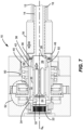
FIG. 7 is a cross-section of the screw drive ofFIG. 1 in a seventh state; -
FIG. 8 is a cross-section of an alternative embodiment of the screw drive ofFIG. 1 in a first state; -
FIG. 9 is a cross-section of the screw drive ofFIG. 8 in a second state; -
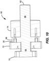
FIG. 10 is a cross-section of the screw drive ofFIG. 8 in a third state; -
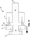
FIG. 11 is a cross-section of the screw drive ofFIG. 8 in a fourth state; -
FIG. 12 is a cross-section of the screw drive ofFIG. 8 in a fifth state; -
FIG. 13 is a cross-section of the screw drive ofFIG. 8 in a sixth state; and -
FIG. 14 is a cross-section of an alternative embodiment of the screw drive ofFIG. 1 . - Corresponding reference characters indicate corresponding parts throughout the several views. The exemplifications set out herein illustrate embodiments of the invention, and such exemplifications are not to be construed as limiting the scope of the invention in any manner.
- Reference will now be made in detail to embodiments of the present invention examples of which are described herein and illustrated in the accompanying drawings. While the invention will be described in conjunction with embodiments, it will be understood that they are not intended to limit the invention to these embodiments. On the contrary, the invention is intended to cover alternatives, modifications and equivalents, which may be included within the scope of the invention as defined by the appended claims.
- Referring to the
figures 1-7 , the actuator of the present invention is described herein in further detail. In the depicted embodiment, thelinear actuator 10 includes ascrew 12 including afirst end portion 42 and asecond end portion 14. In the depicted embodiment, both thefirst end portion 42 and thesecond end portion 14 include cylindrical shaft portions that define a common longitudinal screw axis SA. In the depicted embodiment, thesecond end portion 14 includes ascrew thread 16 defined on an exterior surface. It should be appreciated that many alternative configurations are possible. - In the depicted embodiment, the
linear actuator 10 includes anut 18 coaxially arranged on thesecond end portion 14 of thescrew 12. In the depicted embodiment, thenut 18 has an inner aperture that is configured to mate with thescrew thread 16 of the second cylindrical portion of thescrew 12. In the depicted embodiment, thenut 18 is configured to axially translate along thesecond end portion 14 of thescrew 12 from a retracted position to an extended position when thescrew 12 is rotated relative to thenut 18. It should be appreciated that many alternative configurations are possible. - In the depicted embodiment, the
linear actuator 10 includes a torque transmitting screw drive member that is configured to transmit torque to thescrew 12 to drive the rotation of thescrew 12. According to the invention, the torque transmitting screw drive member takes the form of a slidingdrive gear 20 that includes a female gear 22 (e.g., a female spline gear) at afirst end 24 and a cylindrical lockingsegment interface surface 26 at an opposedsecond end 28. Referring toFIGS. 8-13 , the torque transmitting screw drive member of theactuator 60 is agear member 30 that has an inner aperture mated with a portion of thescrew 12 and having a geared external cylindrical surface. This alternative configuration of the torque transmitting screw drive member will be described in further detail below with reference to the embodiment depicted inFIGS. 8-13 . - In the depicted embodiment shown in
FIGS 1-7 , thelinear actuator 10 includes a mechanical nut locking system configured to automatically lock thenut 18 when thenut 18 is retracted. In the depicted embodiment, the mechanical nut locking system is configured to automatically disengage the mechanical lock when the torque transmitting screw drive member is driven to transmit torque to thescrew 12 in a direction that extends thenut 18. In the depicted embodiment, the locking and unlocking of thenut 18 happens automatically as part of the normal operation of theactuator 10. It should be appreciated that many alternative embodiments are possible including embodiments wherein the locking is less automatic or manual. - In the depicted embodiment, when the torque transmitting screw drive member is rotated in a direction to extend the nut 18 (e.g., clockwise), the torque transmitting screw drive member translates axially prior to transmitting substantial torque to the
screw 12. In the depicted embodiment, the axial translation of the torque transmitting screw drive member operates to disengage (unlock) the mechanical nut locking system. After the mechanical nut locking system is disengaged as a result of the translational movement of the torque transmitting screw drive member, additional rotation of the torque transmitting screw drive member causes thescrew 12 to rotate thereby extending thenut 18. It should be appreciated that many other alternative configurations are also possible. - In the depicted embodiment, when the torque transmitting screw drive member is driven to retract the
nut 18 from an extended position, the screw drive member rotates thescrew 12 to retract thenut 18. After thenut 18 is retracted, the torque transmitting screw drive member subsequently translates axially without further rotating thescrew 12 and this translation engages (locks) the mechanical nut locking system. In the depicted embodiment, the translational movement at both ends of the process is referred to as "loss motion" as there is rotation of the torque transmitting screw drive member that does not directly result in axial translation of thenut 18. It should be appreciated that many other alternative configurations are also possible. - As discussed above, the torque transmitting screw drive member is a sliding
drive gear 20 shown inFIGS. 1-7 . In this depicted embodiment, the slidingdrive gear 20 is generally cylindrical and includes afemale gear 22 at afirst end 24. In the depicted embodiment, the slidingdrive gear 20 includes an annular cavity that has a geared periphery which is configured to engage a geared drive gear/shaft. In the depicted embodiment, the slidingdrive gear 20 includes a cylindrical lockingsegment interface surface 26 at asecond end 28. In the depicted embodiment, the cylindrical lockingsegment interface surface 26 selectively supports the locking segments. In the depicted embodiment, the slidingdrive gear 20 includes ahelical slot 32 that engages apin 34 that extends inwardly from thefirst end portion 42 of thescrew 12. In the depicted embodiment, thehelical slot 32 andpin 34 configuration enables the torque transmitting screw drive member to rotate without rotating thescrew 12. It should be appreciated that many alternative configurations are possible. - In the depicted embodiment, the mechanical nut locking system includes one or
more locking members 36 that extend through a portion of thefirst end portion 42 of thescrew 12. In the depicted embodiment, the lockingmember 36 is a segmented ring. In the depicted embodiment, the lockingmembers 36 are configured to selectively engage a retaininglip 38 of thenut 18. The lockingmembers 36 can be ball bearing structures, pin structures, spring loaded stops, a segmented ring, or any number of other structures. The segments in the depicted embodiment move radially based on the ramped geometry of the cylindrical lockingsegment interface surface 26. In an alternative embodiment, the lockingmembers 36 can be spring biased in a particular direction such as radially inwardly or outwardly. It should be appreciated that many alternative configurations are possible. - In the depicted embodiment, the mechanical nut locking system includes a locking
member retention sleeve 40. In the depicted embodiment, the lockingmember retention sleeve 40 is coaxial with thefirst end portion 42 of thescrew 12 and is spring biased toward thesecond end portion 14 of thescrew 12. In the depicted embodiment, the lockingmember retention sleeve 40 includes a shoulder that slides on thefirst end portion 42 of thescrew 12. In the depicted embodiment, the lockingmember retention sleeve 40 rides against thenut 18 when thenut 18 is retracted and slides into place over the lockingmembers 36 as thenut 18 begins to extend. The lockingmember retention sleeve 40 of the depicted embodiment prevents the lockingmembers 36 from moving out of position. It should be appreciated that many other alternative retention configurations are possible. - In the depicted embodiment, the
first end portion 42 of thescrew 12 defines acylindrical cavity 44 concentric about a longitudinal screw axis SA. In the depicted embodiment, the slidingdrive gear 20 is positioned within thecavity 44. In the depicted embodiment, abearing 52 interfaces between the slidingdrive gear 20 and the nut cavity. It should be appreciated that additional bearings could be incorporated or the existing bearings could be eliminated. Many alternative configurations are possible. - In the depicted embodiment, the
nut 18 includes a first end portion that defines acylindrical nut cavity 46 that is configured to receive a portion of thefirst end portion 42 of thescrew 12. In the depicted embodiment, thenut cavity 46 includes an inwardly radially extending retaininglip 38. In the depicted embodiment, the slidingdrive gear 20 is configured to translate axially which radially biases the lockingmembers 36 into engagement with the retaininglip 38 of thenut cavity 46. As discussed above, the slidingdrive gear 20 is configured to rotate about the screw axis SA and translate axially without rotating thescrew 12. Since thescrew 12 does not rotate during the axial translation of the slidingdrive gear 20, thenut 18 remains stationary during the locking and unlocking operations. In the depicted embodiment, the initial rotation of the slidingdrive gear 20 in a first direction translates the slidingdrive gear 20 without rotating thescrew 12 and subsequent rotation of the slidingdrive gear 20 in the first direction rotates thescrew 12 and drives axial motion of thenut 18. It should be appreciated that many alternative configurations are possible. - In the depicted embodiment, the
actuator 10 includes a no-back system 54 arranged about thefirst end portion 42 of thescrew 12. No-back systems are useful to prevent back driving of thenut 18 when thenut 18 is extended or partially extended. No-back systems can be used with the actuator of the present invention. - In the depicted embodiment, the
actuator 10 comprises a lockingmember retention sleeve 40 coaxially arranged with thefirst end portion 42 of thescrew 12. In the depicted embodiment, thesegment retention sleeve 40 is spring biased toward thesecond end portion 14 of thescrew 12. In the depicted embodiment, the lockingmember retention sleeve 40 includes ashoulder 58 that slides on thefirst end portion 42 of thescrew 12 and alip 50 that engages a portion of a housing to limit the axial translation of the lockingmember retention sleeve 40 in the second direction. In the depicted embodiment, theshoulder 58 in a first position retains the lockingmember 36 in thefirst end portion 42 of thescrew 12. It should be appreciated that many alternative configurations are possible. - The embodiments referring to
FIGS. 8-13 are not according to the invention and are present for illustration purposes only. In the depicted embodiment, thelinear actuator 60 includes ascrew 62 having a firstcylindrical portion 64 and a secondcylindrical portion 66. The firstcylindrical portion 64 includes a first end and a second end. The firstcylindrical portion 64 has a first hand screw lead (e.g., left hand lead) defined on an exterior surface. The secondcylindrical portion 66 includes a first end and a second end. The secondcylindrical portion 66 has a second hand screw lead (e.g., right hand lead) defined on an exterior surface. In the depicted embodiment, theactuator 60 includes aflange 68 located between the firstcylindrical portion 64 and the secondcylindrical portion 66. In the depicted embodiment, theactuator 60 includes amechanical stop 70 located at the first end of the firstcylindrical portion 64 of thescrew 62. In the depicted embodiment, themechanical stop 70 is also a flange. It should be appreciated that many alternative configurations are possible. For example, theflange 68 could be any mechanical stop. - In the depicted embodiment, the
actuator 60 includes anut 74 coaxially arranged on the secondcylindrical portion 66 of thescrew 62. Thenut 74 includes an inner aperture mated with the second hand screw lead of the secondcylindrical portion 66. It should be appreciated that many alternative embodiments are possible. - In the depicted embodiment, the
actuator 60 includes agear member 30 coaxially arranged on the firstcylindrical portion 64 of thescrew 62. In the depicted embodiment, thegear member 30 has an inner aperture mated with the first hand screw lead of the firstcylindrical portion 64 of thescrew 62. In the depicted embodiment, thegear member 30 defines a geared externalcylindrical surface 72. The geared externalcylindrical surface 72 functions as a planetary gear. It should be appreciated that many alternative embodiments are possible. - In the depicted embodiment, the
gear member 30 is configured such that when torque is applied to thegear member 30 in a first direction (counter clockwise) via the geared externalcylindrical surface 72 thegear member 30 rotates about thescrew 62 and translates axially away from theflange 68 until thegear member 30 applies an axial force against themechanical stop 70 at which point the torque transmitted by thegear member 30 drives thescrew 62 to rotate with thegear member 30 and thereby causes thenut 74 to translate axially towards theflange 68. Thegear member 30 can apply an axial force against themechanical stop 70 via direct contact or via contacting other components that press up against themechanical stop 70. It should be appreciated that many alternative configurations are possible. - In the depicted embodiment, the
gear member 30 is configured such that when torque is applied to thegear member 30 in a second direction (clockwise) via the geared externalcylindrical surface 72 thegear member 30 rotates about thescrew 62 and translates axially until thegear member 30 applies an axial force against theflange 68 at which point the torque drives thescrew 62 to rotate with thegear member 30 and thereby causes thenut 74 to translate axially away from theflange 68. Thegear member 30 can apply the axial force against theflange 68 by abutting against theflange 68 or by abutting against components that are abutted against theflange 68. It should be appreciated that many alternative configurations are possible. - In the depicted embodiment, the
actuator 60 is configured such that when thegear member 30 applies an axial force on theflange 68 and thenut 74 is in a retracted position at least one axially extendingflange pin 66 extends from thegear member 30 through theflange 68 into thenut 74 and thereby prevents relative rotation between thenut 74 and thescrew 62. It should be appreciated that many alternative configurations are possible. - In the depicted embodiment, the
actuator 60 is configured such that when torque is applied to thegear member 30 in a second direction (clockwise) via the geared externalcylindrical surface 72 thegear member 30 rotates and translates axially towards themechanical stop 70. In the depicted embodiment, when torque in the second direction is continued to be applied to thegear member 30 thescrew 62 rotates with thegear member 30 which drives thenut 74 to translate axially towards the second end of the second portion of thescrew 62. In the depicted embodiment, the pins (pin 66) that lock thenut 74 from rotating relative to thescrew 62 are retracted as thegear member 30 translates axially towards themechanical stop 70. It should be appreciated that many alternative configurations are possible. - The embodiment referring to
FIG. 14 is not according to the invention and is present for illustration purposes only. In the depicted embodiment, theactuator 80 includes an axially translating lockingsleeve 82 that extends over aflange 84. In the depicted embodiment, theflange 84 includes arim portion 86 that extends radially towards a nut 88. In the depicted embodiment, the nut 88 includes a radial lockingmember recess 90 that receives aradially locking member 92. In the depicted embodiment, theradially locking member 92 is held in engagement with the radial lockingmember recess 90 when the translating lockingsleeve 82 is biased against theflange 84 by agear member 94. In the depicted embodiment, the translating lockingsleeve 82 is spring biased towards the first end of the first cylindrical portion of the screw 96. In the depicted embodiment, when thegear member 94 translates axially away from theflange 84 the translating lockingsleeve 82 moves axially towards the first end of the first cylindrical portion thereby allowing theradially locking member 92 to move radially outwardly from the radial lockingmember recess 90. - The sliding drive gear of the linear actuator may include a generally cylindrical body, a first end portion including an annular cavity having a gear periphery configured to engage a geared drive, and a second end portion having a cylindrical outer surface configured to selectively support the locking segments.
- The sliding drive gear of the linear actuator may include a helical slot that engages a pin that extends inwardly from the first end portion of the screw.
- The linear actuator may comprise a locking member retention sleeve coaxial with the first end portion of the screw, the locking member retention sleeve is spring biased toward the second end portion of the screw.
- The linear actuator may comprise a locking member retention sleeve coaxial with the first end portion of the screw and spring biased toward the second end portion of the screw, wherein the locking member retention sleeve includes a shoulder that slides on the first end portion of the screw and a lip that engages a portion of a housing to limit the translation of the locking member retention sleeve in the second direction, wherein the shoulder in a first position retains the locking segment in the first end portion of the screw.
- The various embodiments described above are provided by way of illustration only and should not be construed to limit the claims attached hereto. Those skilled in the art will readily recognize various modifications and changes that may be made without following the example embodiments and applications illustrated and described herein, and without departing from the scope of the invention which is defined in the accompanying claims.
Claims (4)
- A linear actuator (10) comprising:a screw (12) including a first end portion (42) and a second end portion (14), the second end portion including a cylindrical shaft portion that defines a longitudinal screw axis (SA), the second end portion having an external thread (16);a nut (18) coaxially arranged on the second end portion (14) having an inner aperture having an internal thread mated with the external thread (16) of the second end portion, the nut configured to axially translate along the second end portion from a retracted position to an extended position;a torque transmitting screw drive member that is configured to transmit torque to the screw (12) and drive the rotation of the screw about the longitudinal screw axis; anda mechanical nut locking system configured to automatically lock the nut when the nut (18) is retracted, wherein the mechanical nut locking system automatically disengages the mechanical lock when the torque transmitting screw drive member transmits torque to the screw (12) in a direction that extends the nut,characterized in thatthe first end portion (42) of the screw (12) defines a cylindrical cavity (44) concentric about the longitudinal screw axis (SA), wherein the second end portion (14) of the screw defines a cylindrical shaft portion concentric about the longitudinal screw axis;a first end portion of the nut (16) defines a cylindrical nut cavity (46) that is configured to receive a portion of the first end portion (42) of the screw (12), the nut cavity including an inwardly radially extending retaining lip (38);and in that the linear actuator (10) further comprises:a locking member (36) extending through a portion of the first end portion of the screw and configured to catch on the retaining lip (38) of the nut cavity (46) when in a first position; anda sliding drive gear (20) including a gear interface (22) at a first end (24) and a locking member interface (26) at a second end (28), wherein the sliding drive gear is configured to extend and retract axially and thereby radially bias the locking member (36) into engagement with the retaining lip (38) of the nut cavity (46);wherein initial rotation of the sliding drive gear (20) in a first direction translates the sliding drive gear axially without rotating the screw (12) and subsequent rotation of the sliding drive gear in the first direction rotates the screw and thereby drives axial motion of the nut (16).
- The linear actuator of claim 1, wherein the sliding drive gear (20) includes a generally cylindrical body, a first end portion including an annular cavity having a gear periphery configured to engage a geared drive, and a second end portion having a cylindrical outer surface configured to selectively support the locking segments, wherein the sliding drive gear includes a helical slot (32) that engages a pin (34) that extends inwardly from the first end portion of the screw (12).
- The linear actuator of claim 1, further comprising a locking member retention sleeve (40) coaxial with the first end portion (42) of the screw (12) and spring biased toward the second end portion (14) of the screw, wherein the locking member retention sleeve includes a shoulder (58) that slides on the first end portion (42) of the screw (12) and a lip (50) that engages a portion of a housing to limit the translation of the locking member retention sleeve in the second direction, wherein the shoulder in a first position retains the locking segment in the first end portion of the screw.
- The linear actuator of claim 1, wherein the locking member (36) is a segmented ring.
Applications Claiming Priority (1)
| Application Number | Priority Date | Filing Date | Title |
|---|---|---|---|
| US202163139574P | 2021-01-20 | 2021-01-20 |
Publications (2)
| Publication Number | Publication Date |
|---|---|
| EP4033123A1 EP4033123A1 (en) | 2022-07-27 |
| EP4033123B1 true EP4033123B1 (en) | 2024-02-28 |
Family
ID=79831301
Family Applications (1)
| Application Number | Title | Priority Date | Filing Date |
|---|---|---|---|
| EP22152559.5A Active EP4033123B1 (en) | 2021-01-20 | 2022-01-20 | Screw drive with self-locking mechanism |
Country Status (2)
| Country | Link |
|---|---|
| US (1) | US20220228654A1 (en) |
| EP (1) | EP4033123B1 (en) |
Families Citing this family (1)
| Publication number | Priority date | Publication date | Assignee | Title |
|---|---|---|---|---|
| US11204082B2 (en) * | 2020-01-17 | 2021-12-21 | Steering Solutions Ip Holding Corporation | Steer by wire rotational travel stop |
Family Cites Families (23)
| Publication number | Priority date | Publication date | Assignee | Title |
|---|---|---|---|---|
| US3583248A (en) * | 1969-04-23 | 1971-06-08 | Abex Ind Canada Ltd | Actuator with no-back mechanism |
| US4030578A (en) * | 1976-05-03 | 1977-06-21 | The Boeing Company | Torque limiter |
| US4459867A (en) * | 1981-12-28 | 1984-07-17 | Sundstrand Corporation | Resettable force limiting device |
| US5299666A (en) * | 1992-09-24 | 1994-04-05 | Sundstrand Corporation | Resettable pilot operated torque limiter |
| US6109415A (en) | 1998-05-29 | 2000-08-29 | The Boeing Company | Bi-directional ballscrew no-back device |
| GB0105270D0 (en) * | 2001-03-02 | 2001-04-18 | Lucas Industries Ltd | No-back device |
| US6719106B1 (en) * | 2002-12-17 | 2004-04-13 | The Boeing Company | Duplex skewed-roller brake disc |
| GB0604520D0 (en) * | 2006-03-07 | 2006-04-12 | Smiths Group Plc | Actuators |
| GB0917059D0 (en) * | 2009-09-29 | 2009-11-11 | Goodrich Actuation Systems Ltd | No-back arrangement |
| US10066715B2 (en) * | 2015-04-24 | 2018-09-04 | Moog Inc. | Fail-safe electromechanical actuator |
| WO2017170291A1 (en) * | 2016-03-30 | 2017-10-05 | Ntn株式会社 | Electric actuator |
| US10443696B1 (en) * | 2016-08-03 | 2019-10-15 | Rockwell Collins, Inc. | No-back brake creep inhibitor |
| US10663046B2 (en) * | 2016-09-28 | 2020-05-26 | Linear Transfer Automation | Ball screw locking apparatus |
| FR3063532B1 (en) * | 2017-03-06 | 2019-04-05 | Safran Electronics & Defense | ACTUATOR EQUIPPED WITH A NO BACK SYSTEM WITH INHIBITION AREA |
| EP3406888B1 (en) * | 2017-05-22 | 2022-03-23 | Goodrich Actuation Systems Limited | Actuator |
| DE102017115183A1 (en) * | 2017-07-06 | 2019-01-10 | Edscha Engineering Gmbh | Drive device for a vehicle door |
| US10975940B2 (en) * | 2017-08-24 | 2021-04-13 | Eaton Intelligent Power Limited | Actuator and method |
| DE102019114479A1 (en) * | 2019-05-29 | 2020-12-03 | Liebherr-Aerospace Lindenberg Gmbh | Backstop for aircraft control systems |
| DE102020201142A1 (en) * | 2019-06-05 | 2020-12-10 | Continental Teves Ag & Co. Ohg | Centering mechanism with a brake piston of a disc brake |
| US11505313B2 (en) * | 2019-10-29 | 2022-11-22 | Textron Innovations Inc. | Conversion actuation systems and methods for tiltrotor aircraft |
| US11067156B1 (en) * | 2020-07-21 | 2021-07-20 | Hi-Lex Controls, Inc. | Friction brake and power strut therewith |
| US11623739B2 (en) * | 2020-10-27 | 2023-04-11 | Eaton Intelligent Power Limited | Electromechanical actuator with no-back system |
| TWM610053U (en) * | 2020-12-21 | 2021-04-01 | 第一傳動科技股份有限公司 | Electric push rod with double-brake mechanism |
-
2022
- 2022-01-18 US US17/577,936 patent/US20220228654A1/en active Pending
- 2022-01-20 EP EP22152559.5A patent/EP4033123B1/en active Active
Also Published As
| Publication number | Publication date |
|---|---|
| EP4033123A1 (en) | 2022-07-27 |
| US20220228654A1 (en) | 2022-07-21 |
Similar Documents
| Publication | Publication Date | Title |
|---|---|---|
| EP2604514B1 (en) | Automatically locking linear actuator | |
| EP3552956B1 (en) | Method of operation of a linear actuator | |
| US10421476B2 (en) | Self-locking telescope actuator of a steering column assembly | |
| US5916325A (en) | Actuator assembly and torque limiting system for same | |
| EP2169269B2 (en) | Actuator | |
| US4607180A (en) | Failure tolerant linear drive mechanism intended for celestial space applications | |
| US20070220998A1 (en) | Actuators | |
| EP4033123B1 (en) | Screw drive with self-locking mechanism | |
| US20130299631A1 (en) | Drive screw assembly and landing gear assembly with same | |
| US20220389992A1 (en) | Locking compound rotary actuator | |
| US11746865B2 (en) | Compound rotary actuator with separately commanded lock actuation | |
| KR20170005442A (en) | Ball screw electromechanical actuator for a clutch | |
| US20070012126A1 (en) | Electro-mechanical screw actuator assembly | |
| CN112713708A (en) | Quick release push rod capable of releasing smoothly | |
| CN219299900U (en) | Parking lock device for motor vehicle and motor vehicle | |
| US20220307563A1 (en) | Actuation device for an electromechanically actuatable motor vehicle brake | |
| CN116201861A (en) | Spindle drive and method for operating such a spindle drive | |
| WO2019141562A1 (en) | Disk clutch assembly |
Legal Events
| Date | Code | Title | Description |
|---|---|---|---|
| PUAI | Public reference made under article 153(3) epc to a published international application that has entered the european phase |
Free format text: ORIGINAL CODE: 0009012 |
|
| STAA | Information on the status of an ep patent application or granted ep patent |
Free format text: STATUS: THE APPLICATION HAS BEEN PUBLISHED |
|
| AK | Designated contracting states |
Kind code of ref document: A1 Designated state(s): AL AT BE BG CH CY CZ DE DK EE ES FI FR GB GR HR HU IE IS IT LI LT LU LV MC MK MT NL NO PL PT RO RS SE SI SK SM TR |
|
| STAA | Information on the status of an ep patent application or granted ep patent |
Free format text: STATUS: REQUEST FOR EXAMINATION WAS MADE |
|
| 17P | Request for examination filed |
Effective date: 20230123 |
|
| RBV | Designated contracting states (corrected) |
Designated state(s): AL AT BE BG CH CY CZ DE DK EE ES FI FR GB GR HR HU IE IS IT LI LT LU LV MC MK MT NL NO PL PT RO RS SE SI SK SM TR |
|
| P01 | Opt-out of the competence of the unified patent court (upc) registered |
Effective date: 20230521 |
|
| GRAP | Despatch of communication of intention to grant a patent |
Free format text: ORIGINAL CODE: EPIDOSNIGR1 |
|
| STAA | Information on the status of an ep patent application or granted ep patent |
Free format text: STATUS: GRANT OF PATENT IS INTENDED |
|
| INTG | Intention to grant announced |
Effective date: 20231128 |
|
| RIN1 | Information on inventor provided before grant (corrected) |
Inventor name: CAI, XINGMIN Inventor name: ROBERTS, DANIEL HENRY Inventor name: CURTIS, TYLER QUINCEY |
|
| GRAS | Grant fee paid |
Free format text: ORIGINAL CODE: EPIDOSNIGR3 |
|
| GRAA | (expected) grant |
Free format text: ORIGINAL CODE: 0009210 |
|
| STAA | Information on the status of an ep patent application or granted ep patent |
Free format text: STATUS: THE PATENT HAS BEEN GRANTED |
|
| AK | Designated contracting states |
Kind code of ref document: B1 Designated state(s): AL AT BE BG CH CY CZ DE DK EE ES FI FR GB GR HR HU IE IS IT LI LT LU LV MC MK MT NL NO PL PT RO RS SE SI SK SM TR |
|
| REG | Reference to a national code |
Ref country code: GB Ref legal event code: FG4D |
|
| REG | Reference to a national code |
Ref country code: CH Ref legal event code: EP |
|
| REG | Reference to a national code |
Ref country code: DE Ref legal event code: R096 Ref document number: 602022002082 Country of ref document: DE |
|
| REG | Reference to a national code |
Ref country code: IE Ref legal event code: FG4D |