EP4033108A1 - Gas cylinder - Google Patents
Gas cylinder Download PDFInfo
- Publication number
- EP4033108A1 EP4033108A1 EP20866348.4A EP20866348A EP4033108A1 EP 4033108 A1 EP4033108 A1 EP 4033108A1 EP 20866348 A EP20866348 A EP 20866348A EP 4033108 A1 EP4033108 A1 EP 4033108A1
- Authority
- EP
- European Patent Office
- Prior art keywords
- flow path
- cover
- pressure chamber
- gas
- pressure
- Prior art date
- Legal status (The legal status is an assumption and is not a legal conclusion. Google has not performed a legal analysis and makes no representation as to the accuracy of the status listed.)
- Pending
Links
Images



Classifications
-
- F—MECHANICAL ENGINEERING; LIGHTING; HEATING; WEAPONS; BLASTING
- F15—FLUID-PRESSURE ACTUATORS; HYDRAULICS OR PNEUMATICS IN GENERAL
- F15B—SYSTEMS ACTING BY MEANS OF FLUIDS IN GENERAL; FLUID-PRESSURE ACTUATORS, e.g. SERVOMOTORS; DETAILS OF FLUID-PRESSURE SYSTEMS, NOT OTHERWISE PROVIDED FOR
- F15B15/00—Fluid-actuated devices for displacing a member from one position to another; Gearing associated therewith
- F15B15/20—Other details, e.g. assembly with regulating devices
- F15B15/22—Other details, e.g. assembly with regulating devices for accelerating or decelerating the stroke
- F15B15/222—Other details, e.g. assembly with regulating devices for accelerating or decelerating the stroke having a piston with a piston extension or piston recess which throttles the main fluid outlet as the piston approaches its end position
-
- F—MECHANICAL ENGINEERING; LIGHTING; HEATING; WEAPONS; BLASTING
- F15—FLUID-PRESSURE ACTUATORS; HYDRAULICS OR PNEUMATICS IN GENERAL
- F15B—SYSTEMS ACTING BY MEANS OF FLUIDS IN GENERAL; FLUID-PRESSURE ACTUATORS, e.g. SERVOMOTORS; DETAILS OF FLUID-PRESSURE SYSTEMS, NOT OTHERWISE PROVIDED FOR
- F15B15/00—Fluid-actuated devices for displacing a member from one position to another; Gearing associated therewith
- F15B15/20—Other details, e.g. assembly with regulating devices
- F15B15/22—Other details, e.g. assembly with regulating devices for accelerating or decelerating the stroke
-
- F—MECHANICAL ENGINEERING; LIGHTING; HEATING; WEAPONS; BLASTING
- F15—FLUID-PRESSURE ACTUATORS; HYDRAULICS OR PNEUMATICS IN GENERAL
- F15B—SYSTEMS ACTING BY MEANS OF FLUIDS IN GENERAL; FLUID-PRESSURE ACTUATORS, e.g. SERVOMOTORS; DETAILS OF FLUID-PRESSURE SYSTEMS, NOT OTHERWISE PROVIDED FOR
- F15B15/00—Fluid-actuated devices for displacing a member from one position to another; Gearing associated therewith
- F15B15/08—Characterised by the construction of the motor unit
- F15B15/14—Characterised by the construction of the motor unit of the straight-cylinder type
-
- F—MECHANICAL ENGINEERING; LIGHTING; HEATING; WEAPONS; BLASTING
- F15—FLUID-PRESSURE ACTUATORS; HYDRAULICS OR PNEUMATICS IN GENERAL
- F15B—SYSTEMS ACTING BY MEANS OF FLUIDS IN GENERAL; FLUID-PRESSURE ACTUATORS, e.g. SERVOMOTORS; DETAILS OF FLUID-PRESSURE SYSTEMS, NOT OTHERWISE PROVIDED FOR
- F15B15/00—Fluid-actuated devices for displacing a member from one position to another; Gearing associated therewith
- F15B15/08—Characterised by the construction of the motor unit
- F15B15/14—Characterised by the construction of the motor unit of the straight-cylinder type
- F15B15/1423—Component parts; Constructional details
- F15B15/1433—End caps
-
- F—MECHANICAL ENGINEERING; LIGHTING; HEATING; WEAPONS; BLASTING
- F15—FLUID-PRESSURE ACTUATORS; HYDRAULICS OR PNEUMATICS IN GENERAL
- F15B—SYSTEMS ACTING BY MEANS OF FLUIDS IN GENERAL; FLUID-PRESSURE ACTUATORS, e.g. SERVOMOTORS; DETAILS OF FLUID-PRESSURE SYSTEMS, NOT OTHERWISE PROVIDED FOR
- F15B15/00—Fluid-actuated devices for displacing a member from one position to another; Gearing associated therewith
- F15B15/08—Characterised by the construction of the motor unit
- F15B15/14—Characterised by the construction of the motor unit of the straight-cylinder type
- F15B15/1423—Component parts; Constructional details
- F15B15/1457—Piston rods
-
- F—MECHANICAL ENGINEERING; LIGHTING; HEATING; WEAPONS; BLASTING
- F15—FLUID-PRESSURE ACTUATORS; HYDRAULICS OR PNEUMATICS IN GENERAL
- F15B—SYSTEMS ACTING BY MEANS OF FLUIDS IN GENERAL; FLUID-PRESSURE ACTUATORS, e.g. SERVOMOTORS; DETAILS OF FLUID-PRESSURE SYSTEMS, NOT OTHERWISE PROVIDED FOR
- F15B15/00—Fluid-actuated devices for displacing a member from one position to another; Gearing associated therewith
- F15B15/20—Other details, e.g. assembly with regulating devices
- F15B15/204—Control means for piston speed or actuating force without external control, e.g. control valve inside the piston
-
- F—MECHANICAL ENGINEERING; LIGHTING; HEATING; WEAPONS; BLASTING
- F15—FLUID-PRESSURE ACTUATORS; HYDRAULICS OR PNEUMATICS IN GENERAL
- F15B—SYSTEMS ACTING BY MEANS OF FLUIDS IN GENERAL; FLUID-PRESSURE ACTUATORS, e.g. SERVOMOTORS; DETAILS OF FLUID-PRESSURE SYSTEMS, NOT OTHERWISE PROVIDED FOR
- F15B15/00—Fluid-actuated devices for displacing a member from one position to another; Gearing associated therewith
- F15B15/20—Other details, e.g. assembly with regulating devices
- F15B15/22—Other details, e.g. assembly with regulating devices for accelerating or decelerating the stroke
- F15B15/223—Other details, e.g. assembly with regulating devices for accelerating or decelerating the stroke having a piston with a piston extension or piston recess which completely seals the main fluid outlet as the piston approaches its end position
-
- F—MECHANICAL ENGINEERING; LIGHTING; HEATING; WEAPONS; BLASTING
- F15—FLUID-PRESSURE ACTUATORS; HYDRAULICS OR PNEUMATICS IN GENERAL
- F15B—SYSTEMS ACTING BY MEANS OF FLUIDS IN GENERAL; FLUID-PRESSURE ACTUATORS, e.g. SERVOMOTORS; DETAILS OF FLUID-PRESSURE SYSTEMS, NOT OTHERWISE PROVIDED FOR
- F15B15/00—Fluid-actuated devices for displacing a member from one position to another; Gearing associated therewith
- F15B15/08—Characterised by the construction of the motor unit
- F15B15/14—Characterised by the construction of the motor unit of the straight-cylinder type
- F15B15/1423—Component parts; Constructional details
- F15B15/1428—Cylinders
-
- F—MECHANICAL ENGINEERING; LIGHTING; HEATING; WEAPONS; BLASTING
- F15—FLUID-PRESSURE ACTUATORS; HYDRAULICS OR PNEUMATICS IN GENERAL
- F15B—SYSTEMS ACTING BY MEANS OF FLUIDS IN GENERAL; FLUID-PRESSURE ACTUATORS, e.g. SERVOMOTORS; DETAILS OF FLUID-PRESSURE SYSTEMS, NOT OTHERWISE PROVIDED FOR
- F15B2211/00—Circuits for servomotor systems
- F15B2211/50—Pressure control
- F15B2211/505—Pressure control characterised by the type of pressure control means
- F15B2211/50509—Pressure control characterised by the type of pressure control means the pressure control means controlling a pressure upstream of the pressure control means
-
- F—MECHANICAL ENGINEERING; LIGHTING; HEATING; WEAPONS; BLASTING
- F15—FLUID-PRESSURE ACTUATORS; HYDRAULICS OR PNEUMATICS IN GENERAL
- F15B—SYSTEMS ACTING BY MEANS OF FLUIDS IN GENERAL; FLUID-PRESSURE ACTUATORS, e.g. SERVOMOTORS; DETAILS OF FLUID-PRESSURE SYSTEMS, NOT OTHERWISE PROVIDED FOR
- F15B2211/00—Circuits for servomotor systems
- F15B2211/70—Output members, e.g. hydraulic motors or cylinders or control therefor
- F15B2211/705—Output members, e.g. hydraulic motors or cylinders or control therefor characterised by the type of output members or actuators
- F15B2211/7051—Linear output members
- F15B2211/7053—Double-acting output members
-
- F—MECHANICAL ENGINEERING; LIGHTING; HEATING; WEAPONS; BLASTING
- F15—FLUID-PRESSURE ACTUATORS; HYDRAULICS OR PNEUMATICS IN GENERAL
- F15B—SYSTEMS ACTING BY MEANS OF FLUIDS IN GENERAL; FLUID-PRESSURE ACTUATORS, e.g. SERVOMOTORS; DETAILS OF FLUID-PRESSURE SYSTEMS, NOT OTHERWISE PROVIDED FOR
- F15B2211/00—Circuits for servomotor systems
- F15B2211/70—Output members, e.g. hydraulic motors or cylinders or control therefor
- F15B2211/715—Output members, e.g. hydraulic motors or cylinders or control therefor having braking means
-
- F—MECHANICAL ENGINEERING; LIGHTING; HEATING; WEAPONS; BLASTING
- F15—FLUID-PRESSURE ACTUATORS; HYDRAULICS OR PNEUMATICS IN GENERAL
- F15B—SYSTEMS ACTING BY MEANS OF FLUIDS IN GENERAL; FLUID-PRESSURE ACTUATORS, e.g. SERVOMOTORS; DETAILS OF FLUID-PRESSURE SYSTEMS, NOT OTHERWISE PROVIDED FOR
- F15B2211/00—Circuits for servomotor systems
- F15B2211/80—Other types of control related to particular problems or conditions
- F15B2211/885—Control specific to the type of fluid, e.g. specific to magnetorheological fluid
- F15B2211/8855—Compressible fluids, e.g. specific to pneumatics
Definitions
- the present invention relates to a gas cylinder equipped with a cushioning mechanism that brakes movement of a piston when stopped at a stroke end.
- a cushioning mechanism has been provided in a gas cylinder in order to alleviate shocks occurring at a stoke end of the piston.
- a throttle valve is incorporated in a cover of the gas cylinder, and by manually adjusting a degree of opening of the throttle valve in accordance with usage conditions of the gas cylinder such as the piston speed (cylinder speed) or the like, the amount of gas discharged from a pressure chamber (cushion chamber) between the stroke end and the piston is adjusted via the throttle valve.
- the manual adjustment of the throttle valves is entrusted to the person in charge. Moreover, since the degree of opening of the throttle valves is manually adjusted by a screw type adjustment mechanism, daily maintenance is required such as confirming the presence or absence of looseness of the screws due to vibrations or the like in the production equipment. As a result, it is necessary to repeatedly carry out such manual adjustment.
- the cylinder speed on the stroke end side can be reduced. Consequently, the pressure in the cushion chamber becomes higher than the pressure on the pressurizing chamber side, and a bouncing phenomenon occurs in which the piston is pushed back in a direction opposite to the forward moving direction. As a result, a cycle time is lengthened and a loss is generated in the production equipment.
- the present invention has been devised taking into consideration the aforementioned problems, and has the object of providing a gas cylinder by which a need for manual adjustment is rendered unnecessary, and which is capable of realizing a smooth arrival of the piston at a stroke end and alleviating shocks on the piston while suppressing the occurrence of a bouncing phenomenon.
- An aspect of the present invention relates to a gas cylinder comprising a cylinder tube in which a cylinder chamber is formed, a first cover configured to close one end of the cylinder tube, a second cover configured to close another end of the cylinder tube, a piston configured to partition the cylinder chamber into a first pressure chamber on a side of the first cover and a second pressure chamber on a side of the second cover, and to slide in the cylinder chamber, a piston rod connected to the piston, a first port configured to supply and discharge gas to and from the first pressure chamber, a second port configured to supply and discharge gas to and from the second pressure chamber, and a cushioning mechanism configured to brake movement of the piston when the piston comes to a stop at a stroke end at least on the side of the first cover.
- the cushioning mechanism includes a communication blocking portion configured to block a state of communication between the first pressure chamber and the first port when the piston comes close to the stroke end, an orifice member disposed in the first cover and configured to discharge gas in the first pressure chamber, and a discharge flow rate adjustment part disposed in the first cover and configured to discharge the gas from the first pressure chamber in cooperation with the orifice member, in a case that a pressure in the first pressure chamber exceeds a predetermined pressure.
- the discharge flow rate adjustment part includes a discharge flow path formed inside the first cover and configured to discharge the gas in the first pressure chamber, a spool type valve element disposed midway along the discharge flow path, and an elastic body configured to bias the valve element toward an upstream side of the discharge flow path.
- the valve element blocks a state of communication between an upstream side and a downstream side of the discharge flow path. Further, in the case that the pressure exceeds the predetermined pressure, the valve element is displaced by the pressure toward a downstream side of the discharge flow path in opposition to the biasing force, whereby the upstream side and the downstream side of the discharge flow path are allowed to communicate with each other.
- the valve element blocks the state of communication between the upstream side and the downstream side of the discharge flow path due to the biasing force from the elastic body, the gas in the cushion chamber is discharged only through the orifice member. Further, in the case that the pressure in the first pressure chamber exceeds the predetermined pressure, the valve element is displaced by the pressure in opposition to the biasing force, and allows the upstream side and the downstream side of the discharge flow path to communicate with each other, whereby the gas in the first pressure chamber is discharged through the orifice member and is also discharged through the discharge flow path.
- the gas in the first pressure chamber is discharged through two routes. Consequently, since the gas in the first pressure chamber is discharged in a short time period, the piston can be made to arrive at the stroke end rapidly and smoothly. As a result, while avoiding the occurrence of a bouncing phenomenon, the responsiveness of the gas cylinder can be improved.
- valve element due to the valve element being displaced by a balance between the biasing force of the elastic body and the pressure in the first pressure chamber, the upstream side and the downstream side of the discharge flow path are switched into a state of communication or into a blocked state. Consequently, manual adjustment of the valve element is rendered unnecessary. More specifically, since the valve element is a spool type valve element, in the case that the upstream side and the downstream side of the discharge flow path are placed in communication, the degree of opening of the valve element can be gradually changed in accordance with the magnitude of the pressure in the first pressure chamber.
- the need for manual adjustment of the valve element is rendered unnecessary, and it becomes possible to realize a smooth arrival of the piston at the stroke end and alleviate shocks on the piston while suppressing the occurrence of a bouncing phenomenon.
- a gas cylinder 10A is equipped with a cylindrical cylinder tube 12, a head cover 14 that seals (closes) one end of the cylinder tube 12, and a rod cover 16 that seals (closes) another end of the cylinder tube 12.
- the cylinder tube 12, the head cover 14, and the rod cover 16 are connected in an axial direction of the gas cylinder 10A by a plurality of connecting rods 18 and connecting bolts 20.
- a head side port 22 is formed on an upper surface (one surface) of the head cover 14.
- a rod side port 24 is formed on an upper surface (another surface) of the rod cover 16.
- a piston rod 26 projects and extends out from the rod cover 16.
- the axial direction of the gas cylinder 10A refers to a direction in which the piston rod 26 extends.
- a cylinder chamber 28 is formed inside the cylinder tube 12.
- a piston 30 is arranged which slides in the axial direction between a stroke starting end (stroke end) on the head cover 14 side and a stroke terminal end (stroke end) on the rod cover 16 side.
- the piston 30 divides the cylinder chamber 28 into a head side pressure chamber 32 on the head cover 14 side and a rod side pressure chamber 34 on the rod cover 16 side (see FIGS. 2 and 5A ).
- the piston rod 26 is connected to the piston 30.
- One end of the piston rod 26 is connected to the piston 30.
- Another end of the piston rod 26 penetrates through the rod cover 16 and projects out to the exterior.
- a head side cushion pin 36 is connected to the head cover 14 side of the piston 30.
- On the rod cover 16 side of the piston 30, a rod side cushion pin 38 is mounted on the outer peripheral surface of the piston rod 26.
- a concave head cover chamber 40 into which the head side cushion pin 36 is inserted when the piston 30 comes close to the stroke starting end, is formed in the head cover 14.
- a through hole 42 which penetrates upward through the interior of the head cover 14, is formed on a rear inner side of the head cover chamber 40.
- the head side port 22 is formed by the through hole 42. Accordingly, the head side port 22 carries out supply and discharge of gas to and from the head side pressure chamber 32 via the head cover chamber 40.
- a cushion packing 44 such as an O-ring or the like is provided, which is placed in sliding contact with the head side cushion pin 36 that is inserted into the head cover chamber 40.
- a concave rod cover chamber 46 into which the rod side cushion pin 38 is inserted when the piston 30 comes close to the stroke terminal end, is formed in the rod cover 16.
- a through hole 48 which penetrates upward through the interior of the rod cover 16, is formed on a rear inner side of the rod cover chamber 46.
- the rod side port 24 is formed by the through hole 48. Accordingly, the rod side port 24 carries out supply and discharge of gas to and from the rod side pressure chamber 34 via the rod cover chamber 46.
- a cushion packing 50 such as an O-ring or the like is provided, which is placed in sliding contact with the rod side cushion pin 38 that is inserted into the rod cover chamber 46.
- the gas supplied to and discharged from the head side pressure chamber 32 and the rod side pressure chamber 34 is air, for example. Accordingly, the gas cylinder 10A according to the first embodiment is applied, for example, to an air cylinder.
- a head side cushioning mechanism 52 that brakes movement of the piston 30 when the piston 30 comes to a stop at the stroke starting end is provided on the head cover 14 side of the gas cylinder 10A.
- a rod side cushioning mechanism 54 that brakes movement of the piston 30 when the piston 30 comes to a stop at the stroke terminal end is provided on the rod cover 16 side of the gas cylinder 10A.
- the cushioning mechanism may be provided on at least one of the head cover 14 side or the rod cover 16 side. Further, when the piston 30 comes to a stop at the stroke end (the stroke starting end or the stroke terminal end), a space between the piston 30 and the stroke end (the head side pressure chamber 32 or the rod side pressure chamber 34) serves as a cushion chamber.
- the head side cushioning mechanism 52 includes a communication blocking portion 56 that blocks a state of communication between the head side pressure chamber 32 and the head side port 22 when the piston 30 comes close to the stroke starting end, an orifice member 58 which is disposed in the head cover 14 and through which gas in the head side pressure chamber 32 is discharged, and a discharge flow rate adjustment part 60 (see FIGS. 1 , 3A, and 3B ) which is disposed in the head cover 14, and discharges the gas from the head side pressure chamber 32 in cooperation with the orifice member 58, in the case that the pressure in the head side pressure chamber 32 exceeds a predetermined pressure. As shown in FIGS.
- the orifice member 58 and the discharge flow rate adjustment part 60 are disposed inside the head cover 14 on an upper side (one side portion) with respect to the piston rod 26, so as to be aligned in a direction perpendicular to the axial direction as viewed in plan.
- the communication blocking portion 56 is defined by the head side cushion pin 36 and the cushion packing 44.
- the orifice member 58 is formed from an upstream side flow path 62 that communicates with the head side pressure chamber 32 and extends in the axial direction inside the head cover 14, a downstream side flow path 64 connected to a downstream side of the flow path 62, and extending in a vertical direction inside the head cover 14, and an orifice 66 that allows a lower side of the flow path 64 and the head cover chamber 40 to communicate with each other, and is smaller in diameter than the flow path.
- An upper end of the flow path 64 that extends in the vertical direction is sealed by a steel ball 68.
- the gas in the head side pressure chamber 32 is discharged through the head cover chamber 40 and the head side port 22 from the orifice 66 and each of the flow paths 62 and 64.
- the rod side cushioning mechanism 54 includes a communication blocking portion 70 that blocks a state of communication between the rod side pressure chamber 34 and the rod side port 24 when the piston 30 comes close to the stroke terminal end, an orifice member 72 which is disposed in the rod cover 16 and through which gas is discharged from the rod side pressure chamber 34, and a discharge flow rate adjustment part 74 (see FIGS. 1 , 3A, and 3B ) which is disposed in the rod cover 16, and discharges the gas from the rod side pressure chamber 34 in cooperation with the orifice member 72, in the case that the pressure in the rod side pressure chamber 34 exceeds a predetermined pressure. As shown in FIGS.
- the orifice member 72 and the discharge flow rate adjustment part 74 are disposed inside the rod cover 16 on an upper side (one side portion) with respect to the piston rod 26, so as to be aligned in a direction perpendicular to the axial direction as viewed in plan.
- the communication blocking portion 70 is defined by the rod side cushion pin 38 and the cushion packing 50.
- the orifice member 72 is formed from an upstream side flow path 76 that communicates with the rod side pressure chamber 34 and extends in the axial direction inside the rod cover 16, a downstream side flow path 78 connected to a downstream side of the flow path 76, and extending in a vertical direction inside the rod cover 16, and an orifice 80 that allows a lower side of the flow path 78 and the rod cover chamber 46 to communicate with each other, and is smaller in diameter than the flow path 78.
- An upper end of the flow path 78 that extends in the vertical direction is sealed by a steel ball 81.
- the gas in the rod side pressure chamber 34 is discharged through the rod cover chamber 46 and the rod side port 24 from the orifice 80 and each of the flow paths 76 and 78.
- the configurations of the discharge flow rate adjustment parts 60 and 74 are substantially the same. Therefore, in the description that follows, primarily, the discharge flow rate adjustment part 74 of the rod side cushioning mechanism 54 will be described with reference to FIGS. 3A to 4B .
- the discharge flow rate adjustment part 74 includes a discharge flow path 82 formed inside the rod cover 16 and configured to discharge the gas in the rod side pressure chamber 34 to the exterior, a spool type valve element 84 disposed midway along the discharge flow path 82, and a spring member 86 (elastic body) that biases the valve element 84 toward the upstream side of the discharge flow path 82.
- the discharge flow path 82 is formed from a first flow path 82a that communicates with the rod side pressure chamber 34, and extends in the axial direction inside the rod cover 16, a second flow path 82b that extends upward from a downstream side of the first flow path 82a, a third flow path 82c that extends upward from a downstream side of the second flow path 82b and is greater in diameter than the second flow path 82b, and a fourth flow path 82d connected to the third flow path 82c, and extending in the axial direction. Accordingly, a connected portion between the second flow path 82b and the third flow path 82c is formed in a stepped shape.
- a passage 83 extending from the rod side pressure chamber 34 toward the third flow path 82c is formed inside the rod cover 16 substantially coaxially with the fourth flow path 82d.
- the passage 83 serves as a locator hole in order to form the fourth flow path 82d with a drill or the like, and is sealed by a steel ball 85.
- a tapered portion 88 is formed at the location of a connected portion between the second flow path 82b and the third flow path 82c, within the inner peripheral surface of the rod cover 16.
- the third flow path 82c is sealed by a lid portion 90.
- the lid portion 90 is fixed to the rod cover 16 by a retaining clip 92.
- a male thread 94 may be formed on the outer peripheral surface of the lid portion 90.
- a female thread 96 which is screw-engaged with the male thread 94, is formed at the location of the third flow path 82c, within the inner peripheral surface of the rod cover 16.
- the valve element 84 is a columnar shaped spool valve, which is arranged from the second flow path 82b toward the third flow path 82c, and includes a stepped portion.
- the valve element 84 is formed from a small diameter portion 84a that is capable of being inserted into the second flow path 82b, and a large diameter portion 84b, which is connected to the small diameter portion 84a, is arranged in the third flow path 82c, and the diameter of which is greater than the diameter of the small diameter portion 84a.
- the outer peripheral surface of the small diameter portion 84a is provided with a seal member 84c such as an O-ring or the like, which is in sliding contact with a location that forms the second flow path 82b, within the inner peripheral surface of the rod cover 16.
- the large diameter portion 84b is placed in sliding contact with a location that forms the third flow path 82c, within the inner peripheral surface of the rod cover 16.
- a slit 84d is formed on the outer peripheral surface of the large diameter portion 84b along the vertical direction, which is the direction in which the valve element 84 is displaced.
- FIGS. 3B , 4A, and 4B show an exemplary case in which two slits 84d are provided.
- a distal end part of the small diameter portion 84a may be formed in a flat shape as shown in FIGS. 3B and 4A , or may be formed in a needle-like shape.
- the spring member 86 is inserted between the lid portion 90 and the valve element 84 in the third flow path 82c.
- the spring member 86 biases the large diameter portion 84b downward (toward the second flow path 82b side).
- the fourth flow path 82d extends in the axial direction from the large diameter portion 84b side of the third flow path 82c, and communicates with a flow path 98 that extends upward from the rod cover chamber 46 (see FIGS. 2 and 3B ). An upper end of the flow path 98 is sealed by a steel ball 100.
- the fourth flow path 82d communicates with the rod side port 24 via the flow path 98 and the rod cover chamber 46.
- the discharge flow rate adjustment part 74 of the rod side cushioning mechanism 54 has been described above. Concerning the discharge flow rate adjustment part 60 of the head side cushioning mechanism 52, merely by changing the terminology of "rod" to "head,” an explanation can be given in relation to the discharge flow rate adjustment part 60.
- the pressure Ph increases along with the passage of time from time t1, whereas the pressure Pr decreases.
- the pressure Pc decreases temporarily, but generally is maintained at a predetermined pressure. Consequently, the piston 30 is displaced in the axial direction toward the rod cover 16 side, and the piston rod 26 projects out in the axial direction from the rod cover 16.
- valve element 84 is displaced toward the second flow path 82b side by the biasing force of the spring member 86, and the large diameter portion 84b closes the connected portion between the second flow path 82b and the third flow path 82c, whereby the state of communication between the second flow path 82b and the third flow path 82c is blocked.
- the valve element 84 is displaced upward (to the third flow path 82c side) due to the pressure in opposition to the biasing force of the spring member 86.
- the slits 84d are formed in the large diameter portion 84b, when the valve element 84 is displaced upward, the gas existing in the space between the lid portion 90 and the valve element 84 escapes through the slits 84d to the fourth flow path 82d side. Consequently, the valve element 84 can be easily displaced upward.
- valve element 84 is a spool type valve element, and is displaced upward in accordance with the magnitude of the pressure in the rod side pressure chamber 34.
- the large diameter portion 84b separates away from the connected portion between the second flow path 82b and the third flow path 82c, and a slight gap is formed between the (small diameter portion 84a of) the valve element 84 and the tapered portion 88. Consequently, the second flow path 82b and the third flow path 82c communicate with each other, and as shown in FIG. 5A , the gas in the rod side pressure chamber 34 is discharged to the exterior from the rod side port 24 via the orifice member 72 and the rod cover chamber 46, and as shown in FIG.
- the gas is discharged from the rod side port 24 via the first flow path 82a, the second flow path 82b, the slight gap, the third flow path 82c, the fourth flow path 82d, the flow path 98, and the rod cover chamber 46.
- the pressure in the rod side pressure chamber 34 exceeds the predetermined pressure
- the gas in the rod side pressure chamber 34 is discharged through two routes.
- the valve element 84 being displaced upward, the spring member 86 is contracted.
- the valve element 84 is further displaced upward, and the gap between the valve element 84 and the tapered portion 88 becomes large. More specifically, the degree of opening of the valve element 84 becomes large.
- the gas in the rod side pressure chamber 34 is discharged to the exterior from the rod side port 24 via the orifice member 72 and the rod cover chamber 46, and as shown in FIG. 6 , the gas is discharged from the rod side port 24 via the first flow path 82a, the second flow path 82b, the enlarged gap, the third flow path 82c, the fourth flow path 82d, the flow path 98, and the rod cover chamber 46.
- the gas in the rod side pressure chamber 34 is discharged through the aforementioned two routes.
- the valve element 84 being further displaced upward, the spring member 86 is further contracted.
- the degree of opening of the valve element 84 changes in accordance with the magnitude of the pressure in the rod side pressure chamber 34, whereby the pressure can be suppressed to be less than or equal to the predetermined pressure, and the piston 30 can be brought in closer proximity to the stroke terminal end side.
- the impact force that acts on the piston 30 can be reduced.
- the gas cylinder 10A comprises the cylinder tube 12 in which the cylinder chamber 28 is formed, the first cover (one of the head cover 14 or the rod cover 16) that closes the one end of the cylinder tube 12, the second cover (the other of the head cover 14 and the rod cover 16) that closes the other end of the cylinder tube 12, the piston 30 that partitions the cylinder chamber 28 into the first pressure chamber (one of the head side pressure chamber 32 or the rod side pressure chamber 34) on the first cover side and a second pressure chamber (the other of the head side pressure chamber 32 and the rod side pressure chamber 34) on the second cover side, and that slides in the cylinder chamber 28, the piston rod 26 connected to the piston 30, the first port (one of the head side port 22 or the rod side port 24) through which gas is supplied and discharged to and from the first pressure chamber, the second port (the other of the head side port 22 and the rod side port 24) through which gas is supplied and discharged to and from the second pressure chamber, and the cushioning mechanism (the head side cushioning mechanism
- the cushioning mechanism includes the communication blocking portions 56 and 70 that block the state of communication between the first pressure chamber and the first port when the piston 30 comes close to the stroke end, the orifice members 58 and 72 that are disposed in the first cover and that discharge gas in the first pressure chamber, and the discharge flow rate adjustment parts 60 and 74 that are disposed in the first cover and that discharge the gas from the first pressure chamber in cooperation with the orifice members 58 and 72, in the case that the pressure in the first pressure chamber exceeds the predetermined pressure.
- the discharge flow rate adjustment parts 60 and 74 include the discharge flow path 82 formed inside the first cover and configured to discharge the gas in the first pressure chamber, the spool type valve element 84 disposed midway along the discharge flow path 82, and the spring member 86 (elastic body) that biases the valve element 84 toward the upstream side of the discharge flow path 82.
- the valve element 84 blocks the state of communication between the upstream side (the second flow path 82b) and the downstream side (the third flow path 82c) of the discharge flow path 82 by the biasing force of the spring member 86.
- the valve element 84 is displaced by the pressure toward the downstream side of the discharge flow path 82 in opposition to the biasing force, to allow the upstream side and the downstream side of the discharge flow path 82 to communicate with each other.
- the valve element 84 blocks the state of communication between the upstream side and the downstream side of the discharge flow path 82 due to the biasing force from the spring member 86, the gas in the first pressure chamber is discharged only through the orifice members 58 and 72. Further, in the case that the pressure in the first pressure chamber exceeds the predetermined pressure, the valve element 84 is displaced by the pressure in opposition to the biasing force, and allows the upstream side and the downstream side of the discharge flow path 82 to communicate with each other, whereby the gas in the first pressure chamber is discharged through the orifice members 58 and 72, and is also discharged through the discharge flow path 82.
- the gas in the first pressure chamber is discharged through two routes. Consequently, since the gas in the first pressure chamber is discharged in a short time period, the piston 30 can be made to arrive at the stroke end rapidly and smoothly. As a result, while avoiding the occurrence of a bouncing phenomenon, the responsiveness of the gas cylinder 10A can be improved.
- valve element 84 is displaced by a balance between the biasing force of the spring member 86 and the pressure in the first pressure chamber, the upstream side and the downstream side of the discharge flow path 82 are switched into a state of communication or into a blocked state. Consequently, manual adjustment of the valve element 84 is rendered unnecessary. More specifically, since the valve element 84 is a spool type valve element, in the case that the upstream side and the downstream side of the discharge flow path 82 are placed in communication, the degree of opening of the valve element 84 can be gradually changed in accordance with the magnitude of the pressure in the first pressure chamber.
- the need for manual adjustment of the valve element 84 is rendered unnecessary, and it becomes possible to realize a smooth arrival of the piston 30 at the stroke end and alleviate shocks on the piston 30 while suppressing the occurrence of a bouncing phenomenon.
- the discharge flow path 82 is formed from the first flow path 82a that communicates with the first pressure chamber, the second flow path 82b that is connected to the downstream side of the first flow path 82a, the third flow path 82c that is connected to the downstream side of the second flow path 82b and is greater in diameter than the second flow path 82b, and the fourth flow path 82d that is connected to the downstream side of the third flow path 82c and communicates with the exterior.
- the valve element 84 is formed from the small diameter portion 84a that is capable of being inserted into the second flow path 82b, and the large diameter portion 84b, which is connected to the small diameter portion 84a, is arranged in the third flow path 82c, and has a diameter which is greater than the diameter of the small diameter portion 84a.
- the spring member 86 is arranged in the third flow path 82c, and biases the large diameter portion 84b toward the second flow path 82b side.
- the valve element 84 is displaced toward the second flow path 82b side by the biasing force of the spring member 86, and the large diameter portion 84b closes the connected portion between the second flow path 82b and the third flow path 82c, whereby the state of communication between the second flow path 82b and the third flow path 82c is blocked.
- the valve element 84 is displaced by the pressure toward the third flow path 82c side in opposition to the biasing force, whereby the large diameter portion 84b separates away from the connected portion, and the second flow path 82b and the third flow path 82c are allowed to communicate with each other.
- the occurrence of a bouncing phenomenon can be effectively suppressed, and a smooth arrival of the piston 30 at the stroke end can be easily realized.
- the pressure of the gas from the first pressure chamber is received by the small diameter portion 84a, and the biasing force from the spring member 86 is received by the large diameter portion 84b, it becomes possible to ensure a biasing force (spring force) that overcomes the pressure of the gas. More specifically, since the pressure receiving area of the small diameter portion 84a for the gas becomes smaller, the thrust from the gas that acts on the valve element 84 is reduced. Consequently, even if the spring member 86 is small in scale, the spring force can be ensured.
- the outer peripheral surface of the small diameter portion 84a is provided with the seal member 84c which is in sliding contact with the location of the second flow path 82b on the inner peripheral surface of the first cover.
- the tapered portion 88 the diameter of which is reduced from the third flow path 82c toward the second flow path 82b, is formed at the location of the connected portion on the inner peripheral surface of the first cover.
- the slits 84d are formed along the direction of displacement of the valve element 84 on the outer peripheral surface of the large diameter portion 84b. Consequently, when the valve element 84 is displaced toward the third flow path 82c side (when the valve element 84 opens), since the gas existing in the space between the lid portion 90 and the valve element 84 escapes through the slits 84d, the valve element 84 can be easily displaced toward the third flow path 82c side.
- the pressure receiving area of the large diameter portion 84b for the gas in the first pressure chamber becomes small. Consequently, when the valve element 84 is displaced toward the second flow path 82b side (when the valve element 84 closes), since the force (resistance) that the large diameter portion 84b receives from the gas becomes small, the valve element 84 can be made to slide smoothly to the second flow path 82b side.
- the third flow path 82c communicates with the exterior and is closed by the lid portion 90, and the spring member 86 is inserted between the lid portion 90 and the large diameter portion 84b. As a result, replacement of the spring member 86 is facilitated.
- the male thread 94 is formed on the outer peripheral surface of the lid portion 90
- the female thread 96 which is screwed-engaged with the male thread 94, is formed at the location of the lid portion 90 on the inner peripheral surface of the first cover that forms the third flow path 82c. Consequently, by turning the lid portion 90, it becomes possible to easily adjust the biasing force (spring force) of the spring member 86.
- the orifice members 58 and 72 and the discharge flow rate adjustment parts 60 and 74 are collectively disposed inside the first cover on one side portion with respect to the piston rod 26, three of the four surfaces of the first cover can serve as a mounting surface for the gas cylinder 10A. As a result, it becomes possible for a plurality of the gas cylinders 10A to be disposed collectively in a limited space. Further, the gas cylinder 10A can be easily manufactured. Furthermore, it is possible to realize a gas cylinder 10A by which compatibility of the external dimensions with currently available products is maintained.
- FIGS. 8 to 10 concerning a gas cylinder 10B according to a second embodiment.
- the gas cylinder 10B according to the second embodiment differs from the gas cylinder 10A according to the first embodiment, in that the orifices 66 and 80 and the second flow path 82b communicate with each other substantially coaxially, and the fourth flow path 82d communicates with the first port (the head side port 22 or the rod side port 24). Accordingly, in the gas cylinder 10B according to the second embodiment, the orifices 66 and 80, the second flow path 82b, and the third flow path 82c are formed substantially coaxially, and the first flow path 82a and the second flow path 82b are used as flow paths for the orifice members 58 and 72. In accordance with such features, in comparison with the gas cylinder 10A, the number of flow paths in the first cover (the head cover 14 or the rod cover 16) becomes fewer in number, and manufacturing of the first cover is facilitated.
- Operations of the gas cylinder 10B according to the second embodiment are basically the same as the operations of the gas cylinder 10A according to the first embodiment, however, when the piston 30 comes close to the stroke end (the stroke starting end or the stroke terminal end), in the case that the pressure in the first pressure chamber (the head side pressure chamber 32 or the rod side pressure chamber 34) is less than or equal to the predetermined pressure, the gas in the first pressure chamber is discharged through the first flow path 82a, the second flow path 82b, the orifices 66 and 80, the first cover chamber (the head cover chamber 40 or the rod cover chamber 46), and the first port.
- the valve element 84 is displaced upward, and the second flow path 82b and the third flow path 82c are placed in communication, whereby the gas in the first pressure chamber is discharged to the exterior through the first to fourth flow paths 82a to 82d and the first port, in addition to the above route.
- the same advantageous effects as those of the gas cylinder 10A according to the first embodiment can be obtained.
- the second embodiment in comparison with the first embodiment, since the number of the flow paths in the first cover become fewer, the workload required for drilling holes in the first cover is reduced, and manufacturing of the gas cylinder 10B is facilitated.
- the fourth flow path 82d since the fourth flow path 82d communicates with the first port, the gas in the first pressure chamber is rapidly discharged, thereby making it possible to reduce the pressure in the first pressure chamber. As a result, the responsiveness of the gas cylinder 10B can be improved.
- FIGS. 11A and 11B concerning a gas cylinder 10C according to a third embodiment.
- the gas cylinder 10C according to the third embodiment in terms of its external appearance, is substantially the same as the gas cylinder 10B according to the second embodiment (see FIGS. 8 to 10 ).
- a flow path 102 is formed that communicates with the exterior.
- Such a flow path is formed as a fourth flow path 82d that allows the third flow path 82c to communicate with the exterior.
- a flow path for discharging the gas is not formed between the third flow path 82c and the first port (the head side port 22 or the rod side port 24).
- FIG. 11A and FIG. 11B a case is illustrated in which two fourth flow paths 82d are formed in the lid portion 90.
- Operations of the gas cylinder 10C according to the third embodiment are basically the same as the operations of the gas cylinder 10B according to the second embodiment, however, in the case that the pressure in the first chamber exceeds the predetermined pressure, the valve element 84 is displaced upward, and the second flow path 82b and the third flow path 82c are placed in communication. In this case, since the fourth flow path 82d is formed in the lid portion 90, the gas flowing into the third flow path 82c is discharged to the exterior (the atmosphere) through the slits 84d and the fourth flow path 82d.
- the same advantageous effects as those of the gas cylinders 10A and 10B according to the first and second embodiments can be obtained.
- the valve element 84 is displaced to the third flow path 82c side with a lower pressure, the gas in the first pressure chamber is smoothly discharged, and the pressure in the first pressure chamber is rapidly reduced.
- the responsiveness of the gas cylinder 10C is improved.
- the workload required for drilling holes in the first cover is reduced, and manufacturing of the gas cylinder 10C is facilitated.
Landscapes
- Engineering & Computer Science (AREA)
- Physics & Mathematics (AREA)
- Fluid Mechanics (AREA)
- Mechanical Engineering (AREA)
- General Engineering & Computer Science (AREA)
- Actuator (AREA)
Abstract
Description
- The present invention relates to a gas cylinder equipped with a cushioning mechanism that brakes movement of a piston when stopped at a stroke end.
- Conventionally, for example, as disclosed in
JP S61-141804 U JP S63-008405 U JP H06-341411 A JP 3466121 B2 - Incidentally, in the case of operating production equipment in which a plurality of gas cylinders having the same structure are installed, it is necessary to manually adjust the throttle valve for each of the gas cylinders, and therefore, the burden imposed on a person in charge of the production equipment is increased.
- Further, the manual adjustment of the throttle valves is entrusted to the person in charge. Moreover, since the degree of opening of the throttle valves is manually adjusted by a screw type adjustment mechanism, daily maintenance is required such as confirming the presence or absence of looseness of the screws due to vibrations or the like in the production equipment. As a result, it is necessary to repeatedly carry out such manual adjustment.
- Furthermore, since it is necessary for the throttle valve to be incorporated within a limited space inside the cover, it is impossible to increase the cross-sectional area of the gas flow path.
- Further still, in the case that the cylinder speed is of a high speed specification, by manually adjusting the degree of opening of the throttle valve and throttling the amount of gas that is discharged, the cylinder speed on the stroke end side can be reduced. Consequently, the pressure in the cushion chamber becomes higher than the pressure on the pressurizing chamber side, and a bouncing phenomenon occurs in which the piston is pushed back in a direction opposite to the forward moving direction. As a result, a cycle time is lengthened and a loss is generated in the production equipment.
- The present invention has been devised taking into consideration the aforementioned problems, and has the object of providing a gas cylinder by which a need for manual adjustment is rendered unnecessary, and which is capable of realizing a smooth arrival of the piston at a stroke end and alleviating shocks on the piston while suppressing the occurrence of a bouncing phenomenon.
- An aspect of the present invention relates to a gas cylinder comprising a cylinder tube in which a cylinder chamber is formed, a first cover configured to close one end of the cylinder tube, a second cover configured to close another end of the cylinder tube, a piston configured to partition the cylinder chamber into a first pressure chamber on a side of the first cover and a second pressure chamber on a side of the second cover, and to slide in the cylinder chamber, a piston rod connected to the piston, a first port configured to supply and discharge gas to and from the first pressure chamber, a second port configured to supply and discharge gas to and from the second pressure chamber, and a cushioning mechanism configured to brake movement of the piston when the piston comes to a stop at a stroke end at least on the side of the first cover.
- The cushioning mechanism includes a communication blocking portion configured to block a state of communication between the first pressure chamber and the first port when the piston comes close to the stroke end, an orifice member disposed in the first cover and configured to discharge gas in the first pressure chamber, and a discharge flow rate adjustment part disposed in the first cover and configured to discharge the gas from the first pressure chamber in cooperation with the orifice member, in a case that a pressure in the first pressure chamber exceeds a predetermined pressure.
- The discharge flow rate adjustment part includes a discharge flow path formed inside the first cover and configured to discharge the gas in the first pressure chamber, a spool type valve element disposed midway along the discharge flow path, and an elastic body configured to bias the valve element toward an upstream side of the discharge flow path.
- In addition, in the case that the pressure is less than or equal to the predetermined pressure, the valve element blocks a state of communication between an upstream side and a downstream side of the discharge flow path. Further, in the case that the pressure exceeds the predetermined pressure, the valve element is displaced by the pressure toward a downstream side of the discharge flow path in opposition to the biasing force, whereby the upstream side and the downstream side of the discharge flow path are allowed to communicate with each other.
- According to the present invention, in the case that the pressure in the first pressure chamber (the cushion chamber) is less than or equal to a predetermined pressure, since the valve element blocks the state of communication between the upstream side and the downstream side of the discharge flow path due to the biasing force from the elastic body, the gas in the cushion chamber is discharged only through the orifice member. Further, in the case that the pressure in the first pressure chamber exceeds the predetermined pressure, the valve element is displaced by the pressure in opposition to the biasing force, and allows the upstream side and the downstream side of the discharge flow path to communicate with each other, whereby the gas in the first pressure chamber is discharged through the orifice member and is also discharged through the discharge flow path.
- In this manner, in the case that the pressure exceeds the predetermined pressure, the gas in the first pressure chamber is discharged through two routes. Consequently, since the gas in the first pressure chamber is discharged in a short time period, the piston can be made to arrive at the stroke end rapidly and smoothly. As a result, while avoiding the occurrence of a bouncing phenomenon, the responsiveness of the gas cylinder can be improved.
- Further, due to the valve element being displaced by a balance between the biasing force of the elastic body and the pressure in the first pressure chamber, the upstream side and the downstream side of the discharge flow path are switched into a state of communication or into a blocked state. Consequently, manual adjustment of the valve element is rendered unnecessary. More specifically, since the valve element is a spool type valve element, in the case that the upstream side and the downstream side of the discharge flow path are placed in communication, the degree of opening of the valve element can be gradually changed in accordance with the magnitude of the pressure in the first pressure chamber.
- Accordingly, with the present invention, the need for manual adjustment of the valve element is rendered unnecessary, and it becomes possible to realize a smooth arrival of the piston at the stroke end and alleviate shocks on the piston while suppressing the occurrence of a bouncing phenomenon.
-
-
FIG. 1 is a perspective view of a gas cylinder according to a first embodiment; -
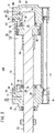
FIG. 2 is a cross-sectional view taken along line II-II ofFIG. 1 ; -
FIG. 3A is a partial plan view of the vicinity of a rod cover of the gas cylinder shown inFIG. 1 ; -
FIG. 3B is a cross-sectional view of principal components taken along line IIIB-IIIB ofFIG. 3A ; -
FIG. 4A is a side view of a valve element; -
FIG. 4B is a plan view of the valve element; -
FIGS. 5A and 5B are a cross-sectional views of principal components showing operations of the gas cylinder shown inFIG. 1 ; -
FIG. 6 is a cross-sectional view of principal components showing operations of the gas cylinder shown inFIG. 1 ; -
FIG. 7 is a timing chart showing operations of the gas cylinder shown inFIG. 1 ; -
FIG. 8 is a perspective view of a gas cylinder according to a second embodiment; -
FIG. 9A is a partial plan view of the vicinity of a rod cover of the gas cylinder shown inFIG. 8 ; -
FIG. 9B is a cross-sectional view of principal components taken along line IXB-IXB ofFIG. 9A ; -
FIG. 10 is a cross-sectional view of principal components showing operations of the gas cylinder shown inFIG. 8 ; -
FIG. 11A is a plan view of a lid portion of a gas cylinder according to a third embodiment; and -
FIG. 11B is a cross-sectional view of principal components showing operations of the gas cylinder. - Hereinafter, preferred embodiments concerning a gas cylinder according to the present invention will be illustrated and described with reference to the accompanying drawings.
- As shown in
FIG. 1 , agas cylinder 10A according to a first embodiment is equipped with acylindrical cylinder tube 12, ahead cover 14 that seals (closes) one end of thecylinder tube 12, and arod cover 16 that seals (closes) another end of thecylinder tube 12. Thecylinder tube 12, thehead cover 14, and therod cover 16 are connected in an axial direction of thegas cylinder 10A by a plurality of connectingrods 18 and connectingbolts 20. Ahead side port 22 is formed on an upper surface (one surface) of thehead cover 14. Arod side port 24 is formed on an upper surface (another surface) of therod cover 16. Apiston rod 26 projects and extends out from therod cover 16. The axial direction of thegas cylinder 10A refers to a direction in which thepiston rod 26 extends. - As shown in
FIG. 2 , acylinder chamber 28 is formed inside thecylinder tube 12. In thecylinder chamber 28, apiston 30 is arranged which slides in the axial direction between a stroke starting end (stroke end) on thehead cover 14 side and a stroke terminal end (stroke end) on therod cover 16 side. Thepiston 30 divides thecylinder chamber 28 into a headside pressure chamber 32 on thehead cover 14 side and a rodside pressure chamber 34 on therod cover 16 side (seeFIGS. 2 and5A ). - The
piston rod 26 is connected to thepiston 30. One end of thepiston rod 26 is connected to thepiston 30. Another end of thepiston rod 26 penetrates through therod cover 16 and projects out to the exterior. A headside cushion pin 36 is connected to thehead cover 14 side of thepiston 30. On therod cover 16 side of thepiston 30, a rodside cushion pin 38 is mounted on the outer peripheral surface of thepiston rod 26. - A concave
head cover chamber 40, into which the headside cushion pin 36 is inserted when thepiston 30 comes close to the stroke starting end, is formed in thehead cover 14. A throughhole 42, which penetrates upward through the interior of thehead cover 14, is formed on a rear inner side of thehead cover chamber 40. Thehead side port 22 is formed by the throughhole 42. Accordingly, thehead side port 22 carries out supply and discharge of gas to and from the headside pressure chamber 32 via thehead cover chamber 40. On thepiston 30 side of thehead cover chamber 40, a cushion packing 44 such as an O-ring or the like is provided, which is placed in sliding contact with the headside cushion pin 36 that is inserted into thehead cover chamber 40. - A concave
rod cover chamber 46, into which the rodside cushion pin 38 is inserted when thepiston 30 comes close to the stroke terminal end, is formed in therod cover 16. A throughhole 48, which penetrates upward through the interior of therod cover 16, is formed on a rear inner side of therod cover chamber 46. Therod side port 24 is formed by the throughhole 48. Accordingly, therod side port 24 carries out supply and discharge of gas to and from the rodside pressure chamber 34 via therod cover chamber 46. On thepiston 30 side of therod cover chamber 46, a cushion packing 50 such as an O-ring or the like is provided, which is placed in sliding contact with the rodside cushion pin 38 that is inserted into therod cover chamber 46. - Moreover, the gas supplied to and discharged from the head
side pressure chamber 32 and the rodside pressure chamber 34 is air, for example. Accordingly, thegas cylinder 10A according to the first embodiment is applied, for example, to an air cylinder. - A head
side cushioning mechanism 52 that brakes movement of thepiston 30 when thepiston 30 comes to a stop at the stroke starting end is provided on thehead cover 14 side of thegas cylinder 10A. Further, a rodside cushioning mechanism 54 that brakes movement of thepiston 30 when thepiston 30 comes to a stop at the stroke terminal end is provided on therod cover 16 side of thegas cylinder 10A. - Moreover, in the
gas cylinder 10A, the cushioning mechanism may be provided on at least one of thehead cover 14 side or therod cover 16 side. Further, when thepiston 30 comes to a stop at the stroke end (the stroke starting end or the stroke terminal end), a space between thepiston 30 and the stroke end (the headside pressure chamber 32 or the rod side pressure chamber 34) serves as a cushion chamber. - The head
side cushioning mechanism 52 includes acommunication blocking portion 56 that blocks a state of communication between the headside pressure chamber 32 and thehead side port 22 when thepiston 30 comes close to the stroke starting end, anorifice member 58 which is disposed in thehead cover 14 and through which gas in the headside pressure chamber 32 is discharged, and a discharge flow rate adjustment part 60 (seeFIGS. 1 ,3A, and 3B ) which is disposed in thehead cover 14, and discharges the gas from the headside pressure chamber 32 in cooperation with theorifice member 58, in the case that the pressure in the headside pressure chamber 32 exceeds a predetermined pressure. As shown inFIGS. 1 to 3B , theorifice member 58 and the discharge flowrate adjustment part 60 are disposed inside thehead cover 14 on an upper side (one side portion) with respect to thepiston rod 26, so as to be aligned in a direction perpendicular to the axial direction as viewed in plan. - In the head
side cushioning mechanism 52, thecommunication blocking portion 56 is defined by the headside cushion pin 36 and the cushion packing 44. By the headside cushion pin 36 and the cushion packing 44 being placed in sliding contact with each other, the state of communication between the headside pressure chamber 32 and thehead side port 22 is blocked. Further, in the headside cushioning mechanism 52, theorifice member 58 is formed from an upstreamside flow path 62 that communicates with the headside pressure chamber 32 and extends in the axial direction inside thehead cover 14, a downstreamside flow path 64 connected to a downstream side of theflow path 62, and extending in a vertical direction inside thehead cover 14, and anorifice 66 that allows a lower side of theflow path 64 and thehead cover chamber 40 to communicate with each other, and is smaller in diameter than the flow path. An upper end of theflow path 64 that extends in the vertical direction is sealed by asteel ball 68. Accordingly, in the case that the state of communication between the headside pressure chamber 32 and thehead side port 22 is blocked, the gas in the headside pressure chamber 32 is discharged through thehead cover chamber 40 and thehead side port 22 from theorifice 66 and each of theflow paths - The rod
side cushioning mechanism 54 includes acommunication blocking portion 70 that blocks a state of communication between the rodside pressure chamber 34 and therod side port 24 when thepiston 30 comes close to the stroke terminal end, anorifice member 72 which is disposed in therod cover 16 and through which gas is discharged from the rodside pressure chamber 34, and a discharge flow rate adjustment part 74 (seeFIGS. 1 ,3A, and 3B ) which is disposed in therod cover 16, and discharges the gas from the rodside pressure chamber 34 in cooperation with theorifice member 72, in the case that the pressure in the rodside pressure chamber 34 exceeds a predetermined pressure. As shown inFIGS. 1 to 3B , theorifice member 72 and the discharge flowrate adjustment part 74 are disposed inside therod cover 16 on an upper side (one side portion) with respect to thepiston rod 26, so as to be aligned in a direction perpendicular to the axial direction as viewed in plan. - In the rod
side cushioning mechanism 54, thecommunication blocking portion 70 is defined by the rodside cushion pin 38 and the cushion packing 50. By the rodside cushion pin 38 and the cushion packing 50 being placed in sliding contact with each other, the state of communication between the rodside pressure chamber 34 and therod side port 24 is blocked. Further, in the rodside cushioning mechanism 54, theorifice member 72 is formed from an upstreamside flow path 76 that communicates with the rodside pressure chamber 34 and extends in the axial direction inside therod cover 16, a downstreamside flow path 78 connected to a downstream side of theflow path 76, and extending in a vertical direction inside therod cover 16, and anorifice 80 that allows a lower side of theflow path 78 and therod cover chamber 46 to communicate with each other, and is smaller in diameter than theflow path 78. An upper end of theflow path 78 that extends in the vertical direction is sealed by asteel ball 81. Accordingly, in the case that the state of communication between the rodside pressure chamber 34 and therod side port 24 is blocked, the gas in the rodside pressure chamber 34 is discharged through therod cover chamber 46 and therod side port 24 from theorifice 80 and each of theflow paths - In the head
side cushioning mechanism 52 and the rodside cushioning mechanism 54, the configurations of the discharge flowrate adjustment parts rate adjustment part 74 of the rodside cushioning mechanism 54 will be described with reference toFIGS. 3A to 4B . - The discharge flow
rate adjustment part 74 includes adischarge flow path 82 formed inside therod cover 16 and configured to discharge the gas in the rodside pressure chamber 34 to the exterior, a spooltype valve element 84 disposed midway along thedischarge flow path 82, and a spring member 86 (elastic body) that biases thevalve element 84 toward the upstream side of thedischarge flow path 82. - The
discharge flow path 82 is formed from afirst flow path 82a that communicates with the rodside pressure chamber 34, and extends in the axial direction inside therod cover 16, asecond flow path 82b that extends upward from a downstream side of thefirst flow path 82a, athird flow path 82c that extends upward from a downstream side of thesecond flow path 82b and is greater in diameter than thesecond flow path 82b, and afourth flow path 82d connected to thethird flow path 82c, and extending in the axial direction. Accordingly, a connected portion between thesecond flow path 82b and thethird flow path 82c is formed in a stepped shape. - A
passage 83 extending from the rodside pressure chamber 34 toward thethird flow path 82c is formed inside therod cover 16 substantially coaxially with thefourth flow path 82d. Thepassage 83 serves as a locator hole in order to form thefourth flow path 82d with a drill or the like, and is sealed by asteel ball 85. - A tapered
portion 88, the diameter of which is reduced from thethird flow path 82c toward thesecond flow path 82b, is formed at the location of a connected portion between thesecond flow path 82b and thethird flow path 82c, within the inner peripheral surface of therod cover 16. - The
third flow path 82c is sealed by alid portion 90. Thelid portion 90 is fixed to therod cover 16 by a retainingclip 92. Moreover, amale thread 94 may be formed on the outer peripheral surface of thelid portion 90. In this case, afemale thread 96, which is screw-engaged with themale thread 94, is formed at the location of thethird flow path 82c, within the inner peripheral surface of therod cover 16. - The
valve element 84 is a columnar shaped spool valve, which is arranged from thesecond flow path 82b toward thethird flow path 82c, and includes a stepped portion. Thevalve element 84 is formed from asmall diameter portion 84a that is capable of being inserted into thesecond flow path 82b, and alarge diameter portion 84b, which is connected to thesmall diameter portion 84a, is arranged in thethird flow path 82c, and the diameter of which is greater than the diameter of thesmall diameter portion 84a. The outer peripheral surface of thesmall diameter portion 84a is provided with aseal member 84c such as an O-ring or the like, which is in sliding contact with a location that forms thesecond flow path 82b, within the inner peripheral surface of therod cover 16. Further, thelarge diameter portion 84b is placed in sliding contact with a location that forms thethird flow path 82c, within the inner peripheral surface of therod cover 16. Aslit 84d is formed on the outer peripheral surface of thelarge diameter portion 84b along the vertical direction, which is the direction in which thevalve element 84 is displaced.FIGS. 3B ,4A, and 4B show an exemplary case in which twoslits 84d are provided. Moreover, a distal end part of thesmall diameter portion 84a may be formed in a flat shape as shown inFIGS. 3B and4A , or may be formed in a needle-like shape. - The
spring member 86 is inserted between thelid portion 90 and thevalve element 84 in thethird flow path 82c. Thespring member 86 biases thelarge diameter portion 84b downward (toward thesecond flow path 82b side). - The
fourth flow path 82d extends in the axial direction from thelarge diameter portion 84b side of thethird flow path 82c, and communicates with aflow path 98 that extends upward from the rod cover chamber 46 (seeFIGS. 2 and3B ). An upper end of theflow path 98 is sealed by asteel ball 100. Thefourth flow path 82d communicates with therod side port 24 via theflow path 98 and therod cover chamber 46. - The discharge flow
rate adjustment part 74 of the rodside cushioning mechanism 54 has been described above. Concerning the discharge flowrate adjustment part 60 of the headside cushioning mechanism 52, merely by changing the terminology of "rod" to "head," an explanation can be given in relation to the discharge flowrate adjustment part 60. - A description will be given concerning operations of the
gas cylinder 10A according to the first embodiment which is configured in the manner described above. In this instance, a description will be given concerning operations of the rod side cushioning mechanism 54 (cushioning mechanism) in the case that thepiston 30 arrives at the stroke terminal end (stroke end) on the rod cover 16 (first cover) side. - First, at time t1 in
FIG. 7 , supply of the gas from the head side port 22 (second port) to the head side pressure chamber 32 (second pressure chamber) via thehead cover chamber 40 is initiated, together with discharging of the gas from the rod side pressure chamber 34 (first pressure chamber) via therod cover chamber 46 and the rod side port 24 (first port) being initiated. InFIG. 7 , Ph indicates the pressure (head side pressure) of the gas supplied from thehead side port 22 to the headside pressure chamber 32. Pr indicates the pressure (rod side pressure) of the gas discharged from therod side port 24. Pc indicates the pressure (cushion pressure) in the rodside pressure chamber 34. - In this case, the pressure Ph increases along with the passage of time from time t1, whereas the pressure Pr decreases. On the other hand, the pressure Pc decreases temporarily, but generally is maintained at a predetermined pressure. Consequently, the
piston 30 is displaced in the axial direction toward therod cover 16 side, and thepiston rod 26 projects out in the axial direction from therod cover 16. - Next, when the rod
side cushion pin 38 enters therod cover chamber 46, and the rodside cushion pin 38 and the cushion packing 50 of therod cover chamber 46 are placed in sliding contact with each other, the state of communication between therod side port 24 and the rodside pressure chamber 34 via therod cover chamber 46 is blocked. Consequently, the pressure in the rodside pressure chamber 34 increases. In this case, as shown inFIG. 5A , the gas in the rodside pressure chamber 34 is discharged from therod side port 24 via the orifice member 72 (the twoflow paths rod cover chamber 46. If the pressure in the rodside pressure chamber 34 is less than or equal to a predetermined pressure (0.5 MPa inFIG. 7 ), thevalve element 84 is displaced toward thesecond flow path 82b side by the biasing force of thespring member 86, and thelarge diameter portion 84b closes the connected portion between thesecond flow path 82b and thethird flow path 82c, whereby the state of communication between thesecond flow path 82b and thethird flow path 82c is blocked. - Next, at time t2, in the case that the pressure in the rod
side pressure chamber 34 exceeds the predetermined pressure, thevalve element 84 is displaced upward (to thethird flow path 82c side) due to the pressure in opposition to the biasing force of thespring member 86. In this case, since theslits 84d are formed in thelarge diameter portion 84b, when thevalve element 84 is displaced upward, the gas existing in the space between thelid portion 90 and thevalve element 84 escapes through theslits 84d to thefourth flow path 82d side. Consequently, thevalve element 84 can be easily displaced upward. - Further, the
valve element 84 is a spool type valve element, and is displaced upward in accordance with the magnitude of the pressure in the rodside pressure chamber 34. In this case, as shown inFIG. 5B , thelarge diameter portion 84b separates away from the connected portion between thesecond flow path 82b and thethird flow path 82c, and a slight gap is formed between the (small diameter portion 84a of) thevalve element 84 and the taperedportion 88. Consequently, thesecond flow path 82b and thethird flow path 82c communicate with each other, and as shown inFIG. 5A , the gas in the rodside pressure chamber 34 is discharged to the exterior from therod side port 24 via theorifice member 72 and therod cover chamber 46, and as shown inFIG. 5B , the gas is discharged from therod side port 24 via thefirst flow path 82a, thesecond flow path 82b, the slight gap, thethird flow path 82c, thefourth flow path 82d, theflow path 98, and therod cover chamber 46. In other words, when the pressure in the rodside pressure chamber 34 exceeds the predetermined pressure, the gas in the rodside pressure chamber 34 is discharged through two routes. Moreover, by thevalve element 84 being displaced upward, thespring member 86 is contracted. - Then, when the pressure in the rod
side pressure chamber 34 increases further, thevalve element 84 is further displaced upward, and the gap between thevalve element 84 and the taperedportion 88 becomes large. More specifically, the degree of opening of thevalve element 84 becomes large. As a result, as shown inFIG. 5A , the gas in the rodside pressure chamber 34 is discharged to the exterior from therod side port 24 via theorifice member 72 and therod cover chamber 46, and as shown inFIG. 6 , the gas is discharged from therod side port 24 via thefirst flow path 82a, thesecond flow path 82b, the enlarged gap, thethird flow path 82c, thefourth flow path 82d, theflow path 98, and therod cover chamber 46. In this case as well, the gas in the rodside pressure chamber 34 is discharged through the aforementioned two routes. Moreover, by thevalve element 84 being further displaced upward, thespring member 86 is further contracted. - In the foregoing manner, in a time block from time t2 to time t3, the degree of opening of the
valve element 84 changes in accordance with the magnitude of the pressure in the rodside pressure chamber 34, whereby the pressure can be suppressed to be less than or equal to the predetermined pressure, and thepiston 30 can be brought in closer proximity to the stroke terminal end side. As a result, at time t3, when thepiston 30 has arrived at the stroke terminal end, the impact force that acts on thepiston 30 can be reduced. - In this manner, the gas cylinder 10A according to the first embodiment comprises the cylinder tube 12 in which the cylinder chamber 28 is formed, the first cover (one of the head cover 14 or the rod cover 16) that closes the one end of the cylinder tube 12, the second cover (the other of the head cover 14 and the rod cover 16) that closes the other end of the cylinder tube 12, the piston 30 that partitions the cylinder chamber 28 into the first pressure chamber (one of the head side pressure chamber 32 or the rod side pressure chamber 34) on the first cover side and a second pressure chamber (the other of the head side pressure chamber 32 and the rod side pressure chamber 34) on the second cover side, and that slides in the cylinder chamber 28, the piston rod 26 connected to the piston 30, the first port (one of the head side port 22 or the rod side port 24) through which gas is supplied and discharged to and from the first pressure chamber, the second port (the other of the head side port 22 and the rod side port 24) through which gas is supplied and discharged to and from the second pressure chamber, and the cushioning mechanism (the head side cushioning mechanism 52, the rod side cushioning mechanism 54) that brakes the movement of the piston 30 when the piston 30 comes to a stop at a stroke end (the stroke starting end or the stroke terminal end) at least on the first cover side.
- The cushioning mechanism includes the
communication blocking portions piston 30 comes close to the stroke end, theorifice members rate adjustment parts orifice members - The discharge flow
rate adjustment parts discharge flow path 82 formed inside the first cover and configured to discharge the gas in the first pressure chamber, the spooltype valve element 84 disposed midway along thedischarge flow path 82, and the spring member 86 (elastic body) that biases thevalve element 84 toward the upstream side of thedischarge flow path 82. - In addition, in the case that the pressure is less than or equal to the predetermined pressure, the
valve element 84 blocks the state of communication between the upstream side (thesecond flow path 82b) and the downstream side (thethird flow path 82c) of thedischarge flow path 82 by the biasing force of thespring member 86. On the other hand, in the case that the pressure exceeds the predetermined pressure, thevalve element 84 is displaced by the pressure toward the downstream side of thedischarge flow path 82 in opposition to the biasing force, to allow the upstream side and the downstream side of thedischarge flow path 82 to communicate with each other. - In the case that the pressure in the first pressure chamber (the cushion chamber) is less than or equal to the predetermined pressure, since the
valve element 84 blocks the state of communication between the upstream side and the downstream side of thedischarge flow path 82 due to the biasing force from thespring member 86, the gas in the first pressure chamber is discharged only through theorifice members valve element 84 is displaced by the pressure in opposition to the biasing force, and allows the upstream side and the downstream side of thedischarge flow path 82 to communicate with each other, whereby the gas in the first pressure chamber is discharged through theorifice members discharge flow path 82. - In this manner, in the case that the pressure exceeds the predetermined pressure, the gas in the first pressure chamber is discharged through two routes. Consequently, since the gas in the first pressure chamber is discharged in a short time period, the
piston 30 can be made to arrive at the stroke end rapidly and smoothly. As a result, while avoiding the occurrence of a bouncing phenomenon, the responsiveness of thegas cylinder 10A can be improved. - Further, due to the
valve element 84 being displaced by a balance between the biasing force of thespring member 86 and the pressure in the first pressure chamber, the upstream side and the downstream side of thedischarge flow path 82 are switched into a state of communication or into a blocked state. Consequently, manual adjustment of thevalve element 84 is rendered unnecessary. More specifically, since thevalve element 84 is a spool type valve element, in the case that the upstream side and the downstream side of thedischarge flow path 82 are placed in communication, the degree of opening of thevalve element 84 can be gradually changed in accordance with the magnitude of the pressure in the first pressure chamber. - Accordingly, with the
gas cylinder 10A, the need for manual adjustment of thevalve element 84 is rendered unnecessary, and it becomes possible to realize a smooth arrival of thepiston 30 at the stroke end and alleviate shocks on thepiston 30 while suppressing the occurrence of a bouncing phenomenon. - In this instance, the
discharge flow path 82 is formed from thefirst flow path 82a that communicates with the first pressure chamber, thesecond flow path 82b that is connected to the downstream side of thefirst flow path 82a, thethird flow path 82c that is connected to the downstream side of thesecond flow path 82b and is greater in diameter than thesecond flow path 82b, and thefourth flow path 82d that is connected to the downstream side of thethird flow path 82c and communicates with the exterior. Thevalve element 84 is formed from thesmall diameter portion 84a that is capable of being inserted into thesecond flow path 82b, and thelarge diameter portion 84b, which is connected to thesmall diameter portion 84a, is arranged in thethird flow path 82c, and has a diameter which is greater than the diameter of thesmall diameter portion 84a. Thespring member 86 is arranged in thethird flow path 82c, and biases thelarge diameter portion 84b toward thesecond flow path 82b side. - In addition, in the case that the pressure is less than or equal to the predetermined pressure, the
valve element 84 is displaced toward thesecond flow path 82b side by the biasing force of thespring member 86, and thelarge diameter portion 84b closes the connected portion between thesecond flow path 82b and thethird flow path 82c, whereby the state of communication between thesecond flow path 82b and thethird flow path 82c is blocked. Further, in the case that the pressure exceeds the predetermined pressure, thevalve element 84 is displaced by the pressure toward thethird flow path 82c side in opposition to the biasing force, whereby thelarge diameter portion 84b separates away from the connected portion, and thesecond flow path 82b and thethird flow path 82c are allowed to communicate with each other. - Consequently, the occurrence of a bouncing phenomenon can be effectively suppressed, and a smooth arrival of the
piston 30 at the stroke end can be easily realized. Further, since the pressure of the gas from the first pressure chamber is received by thesmall diameter portion 84a, and the biasing force from thespring member 86 is received by thelarge diameter portion 84b, it becomes possible to ensure a biasing force (spring force) that overcomes the pressure of the gas. More specifically, since the pressure receiving area of thesmall diameter portion 84a for the gas becomes smaller, the thrust from the gas that acts on thevalve element 84 is reduced. Consequently, even if thespring member 86 is small in scale, the spring force can be ensured. - Further, the outer peripheral surface of the
small diameter portion 84a is provided with theseal member 84c which is in sliding contact with the location of thesecond flow path 82b on the inner peripheral surface of the first cover. The taperedportion 88, the diameter of which is reduced from thethird flow path 82c toward thesecond flow path 82b, is formed at the location of the connected portion on the inner peripheral surface of the first cover. As a result, when thevalve element 84 moves in the direction of displacement, since wear, damage or the like to theseal member 84c due to contact with the connected portion is avoided, the useful lifetime of thegas cylinder 10A including thevalve element 84 can be extended. Further, by forming the taperedportion 88, the degree of opening of thevalve element 84 can be gradually changed when thevalve element 84 is displaced according to the pressure of the gas. - Further, the
slits 84d are formed along the direction of displacement of thevalve element 84 on the outer peripheral surface of thelarge diameter portion 84b. Consequently, when thevalve element 84 is displaced toward thethird flow path 82c side (when thevalve element 84 opens), since the gas existing in the space between thelid portion 90 and thevalve element 84 escapes through theslits 84d, thevalve element 84 can be easily displaced toward thethird flow path 82c side. - Further, by providing the
slits 84d, the pressure receiving area of thelarge diameter portion 84b for the gas in the first pressure chamber becomes small. Consequently, when thevalve element 84 is displaced toward thesecond flow path 82b side (when thevalve element 84 closes), since the force (resistance) that thelarge diameter portion 84b receives from the gas becomes small, thevalve element 84 can be made to slide smoothly to thesecond flow path 82b side. - Furthermore, by providing the
slits 84d, even if rattling occurs on thelarge diameter portion 84b or on the inner peripheral surface of the first cover that forms thethird flow path 82c, the influence of such rattling on the movement of thevalve element 84 can be reduced. - Further, the
third flow path 82c communicates with the exterior and is closed by thelid portion 90, and thespring member 86 is inserted between thelid portion 90 and thelarge diameter portion 84b. As a result, replacement of thespring member 86 is facilitated. - In this case, the
male thread 94 is formed on the outer peripheral surface of thelid portion 90, and thefemale thread 96, which is screwed-engaged with themale thread 94, is formed at the location of thelid portion 90 on the inner peripheral surface of the first cover that forms thethird flow path 82c. Consequently, by turning thelid portion 90, it becomes possible to easily adjust the biasing force (spring force) of thespring member 86. - Further, since the
orifice members rate adjustment parts piston rod 26, three of the four surfaces of the first cover can serve as a mounting surface for thegas cylinder 10A. As a result, it becomes possible for a plurality of thegas cylinders 10A to be disposed collectively in a limited space. Further, thegas cylinder 10A can be easily manufactured. Furthermore, it is possible to realize agas cylinder 10A by which compatibility of the external dimensions with currently available products is maintained. - Next, a description will be given with reference to
FIGS. 8 to 10 concerning agas cylinder 10B according to a second embodiment. Concerning the same constituent elements as those of thegas cylinder 10A according to the first embodiment (seeFIGS. 1 to 7 ), these elements are designated by the same reference numerals, and detailed description of thereof will be omitted. - The
gas cylinder 10B according to the second embodiment differs from thegas cylinder 10A according to the first embodiment, in that theorifices second flow path 82b communicate with each other substantially coaxially, and thefourth flow path 82d communicates with the first port (thehead side port 22 or the rod side port 24). Accordingly, in thegas cylinder 10B according to the second embodiment, theorifices second flow path 82b, and thethird flow path 82c are formed substantially coaxially, and thefirst flow path 82a and thesecond flow path 82b are used as flow paths for theorifice members gas cylinder 10A, the number of flow paths in the first cover (thehead cover 14 or the rod cover 16) becomes fewer in number, and manufacturing of the first cover is facilitated. - Operations of the
gas cylinder 10B according to the second embodiment are basically the same as the operations of thegas cylinder 10A according to the first embodiment, however, when thepiston 30 comes close to the stroke end (the stroke starting end or the stroke terminal end), in the case that the pressure in the first pressure chamber (the headside pressure chamber 32 or the rod side pressure chamber 34) is less than or equal to the predetermined pressure, the gas in the first pressure chamber is discharged through thefirst flow path 82a, thesecond flow path 82b, theorifices head cover chamber 40 or the rod cover chamber 46), and the first port. On the other hand, in the case that the pressure in the first pressure chamber exceeds the predetermined pressure, thevalve element 84 is displaced upward, and thesecond flow path 82b and thethird flow path 82c are placed in communication, whereby the gas in the first pressure chamber is discharged to the exterior through the first tofourth flow paths 82a to 82d and the first port, in addition to the above route. - Therefore, also in the
gas cylinder 10B according to the second embodiment, the same advantageous effects as those of thegas cylinder 10A according to the first embodiment can be obtained. Further, in the case of the second embodiment, in comparison with the first embodiment, since the number of the flow paths in the first cover become fewer, the workload required for drilling holes in the first cover is reduced, and manufacturing of thegas cylinder 10B is facilitated. Furthermore, in the second embodiment, since thefourth flow path 82d communicates with the first port, the gas in the first pressure chamber is rapidly discharged, thereby making it possible to reduce the pressure in the first pressure chamber. As a result, the responsiveness of thegas cylinder 10B can be improved. - Next, a description will be given with reference to
FIGS. 11A and 11B concerning a gas cylinder 10C according to a third embodiment. - The gas cylinder 10C according to the third embodiment, in terms of its external appearance, is substantially the same as the
gas cylinder 10B according to the second embodiment (seeFIGS. 8 to 10 ). However, in the gas cylinder 10C according to the third embodiment, in thelid portion 90, aflow path 102 is formed that communicates with the exterior. Such a flow path is formed as afourth flow path 82d that allows thethird flow path 82c to communicate with the exterior. Specifically, according to the third embodiment, a flow path for discharging the gas is not formed between thethird flow path 82c and the first port (thehead side port 22 or the rod side port 24). Moreover, inFIG. 11A and FIG. 11B , a case is illustrated in which twofourth flow paths 82d are formed in thelid portion 90. - Operations of the gas cylinder 10C according to the third embodiment are basically the same as the operations of the
gas cylinder 10B according to the second embodiment, however, in the case that the pressure in the first chamber exceeds the predetermined pressure, thevalve element 84 is displaced upward, and thesecond flow path 82b and thethird flow path 82c are placed in communication. In this case, since thefourth flow path 82d is formed in thelid portion 90, the gas flowing into thethird flow path 82c is discharged to the exterior (the atmosphere) through theslits 84d and thefourth flow path 82d. - Therefore, also in the gas cylinder 10C according to the third embodiment, the same advantageous effects as those of the
gas cylinders third flow path 82c is discharged to the exterior (the atmosphere) through theslits 84d and thefourth flow path 82d, thevalve element 84 is displaced to thethird flow path 82c side with a lower pressure, the gas in the first pressure chamber is smoothly discharged, and the pressure in the first pressure chamber is rapidly reduced. As a result, the responsiveness of the gas cylinder 10C is improved. Further, since there is no need to form a flow path for discharging the gas between thethird flow path 82c and the first port, the workload required for drilling holes in the first cover is reduced, and manufacturing of the gas cylinder 10C is facilitated. - It should be noted that the present invention is not limited to the embodiments described above, and it goes without saying that various configurations could be adopted therein based on the content disclosed in the present specification.
Claims (9)
- A gas cylinder (10A to 10C), comprising:a cylinder tube (12) in which a cylinder chamber (28) is formed;a first cover (14, 16) configured to close one end of the cylinder tube;a second cover (14, 16) configured to close another end of the cylinder tube;a piston (30) configured to partition the cylinder chamber into a first pressure chamber (32, 34) on a side of the first cover and a second pressure chamber (32, 34) on a side of the second cover, and to slide in the cylinder chamber;a piston rod (26) connected to the piston;a first port (22, 24) configured to supply and discharge gas to and from the first pressure chamber;a second port (22, 24) configured to supply and discharge gas to and from the second pressure chamber; anda cushioning mechanism (52, 54) configured to brake movement of the piston when the piston comes to a stop at a stroke end at least on the side of the first cover,wherein the cushioning mechanism includes:a communication blocking portion (56, 70) configured to block a state of communication between the first pressure chamber and the first port when the piston comes close to the stroke end;an orifice member (58, 72) disposed in the first cover and configured to discharge gas in the first pressure chamber; anda discharge flow rate adjustment part (60, 74) disposed in the first cover and configured to discharge the gas from the first pressure chamber in cooperation with the orifice member, in a case that a pressure in the first pressure chamber exceeds a predetermined pressure,the discharge flow rate adjustment part includes a discharge flow path (82) formed inside the first cover and configured to discharge the gas in the first pressure chamber, a spool type valve element (84) disposed midway along the discharge flow path, and an elastic body (86) configured to bias the valve element toward an upstream side of the discharge flow path,the discharge flow path is formed from a first flow path (82a) configured to communicate with the first pressure chamber, a second flow path (82b) connected to a downstream side of the first flow path, a third flow path (82c) connected to a downstream side of the second flow path and having a larger diameter than the second flow path, and a fourth flow path (82d) connected to the third flow path and configured to communicate with an exterior,the valve element is formed from a small diameter portion (84a) configured to be inserted into the second flow path, and a large diameter portion (84b) that is connected to the small diameter portion, is disposed in the third flow path, and has a larger diameter than the small diameter portion,the elastic body is a spring member disposed in the third flow path and configured to bias the large diameter portion toward a side of the second flow path,in a case that the pressure is less than or equal to the predetermined pressure, the valve element is displaced toward the side of the second flow path by a biasing force of the spring member, and the large diameter portion closes a connected portion between the second flow path and the third flow path, whereby a state of communication between the second flow path and the third flow path is blocked, andin the case that the pressure exceeds the predetermined pressure, the valve element is displaced by the pressure toward a side of the third flow path in opposition to the biasing force, whereby the large diameter portion separates away from the connected portion, and the second flow path and the third flow path are allowed to communicate with each other.
- The gas cylinder according to claim 1, wherein:an outer peripheral surface of the small diameter portion is provided with a seal member (84c) in sliding contact with a location of the second flow path on an inner peripheral surface of the first cover; anda tapered portion (88), a diameter of which is reduced from the third flow path toward the second flow path, is formed at a location of the connected portion on the inner peripheral surface.
- The gas cylinder according to claim 1 or 2,
wherein a slit (84d) is formed on an outer peripheral surface of the large diameter portion along a direction in which the valve element is displaced. - The gas cylinder according to any one of claims 1 to 3, wherein:the third flow path communicates with the exterior and is closed by a lid portion (90); andthe spring member is inserted between the lid portion and the large diameter portion.
- The gas cylinder according to claim 4, wherein:a male thread (94) is formed on an outer peripheral surface of the lid portion; anda female thread (96) that is screwed-engaged with the male thread is formed at a location of the lid portion on an inner peripheral surface of the first cover.
- The gas cylinder according to claim 4 or 5, wherein:the first port is formed in the first cover;the second port is formed in the second cover; andthe orifice member includes an orifice (66, 80) configured to discharge, to the first port, gas flowing from the first pressure chamber through the first flow path and the second flow path.
- The gas cylinder according to claim 6, wherein the fourth flow path connects the third flow path and the first port.
- The gas cylinder according to claim 6, wherein the fourth flow path is formed in the lid portion, and allows the third flow path to communicate with the exterior.
- The gas cylinder according to any one of claims 1 to 8, wherein the orifice member and the discharge flow rate adjustment part are disposed collectively inside the first cover on one side portion with respect to the piston rod.
Applications Claiming Priority (2)
| Application Number | Priority Date | Filing Date | Title |
|---|---|---|---|
| JP2019171018A JP6808186B1 (en) | 2019-09-20 | 2019-09-20 | Gas cylinder |
| PCT/JP2020/027995 WO2021053959A1 (en) | 2019-09-20 | 2020-07-20 | Gas cylinder |
Publications (2)
| Publication Number | Publication Date |
|---|---|
| EP4033108A1 true EP4033108A1 (en) | 2022-07-27 |
| EP4033108A4 EP4033108A4 (en) | 2023-09-06 |
Family
ID=73992837
Family Applications (1)
| Application Number | Title | Priority Date | Filing Date |
|---|---|---|---|
| EP20866348.4A Pending EP4033108A4 (en) | 2019-09-20 | 2020-07-20 | GAS CYLINDER |
Country Status (7)
| Country | Link |
|---|---|
| US (1) | US11898583B2 (en) |
| EP (1) | EP4033108A4 (en) |
| JP (1) | JP6808186B1 (en) |
| KR (1) | KR102852388B1 (en) |
| CN (1) | CN114450492B (en) |
| TW (1) | TWI749769B (en) |
| WO (1) | WO2021053959A1 (en) |
Family Cites Families (24)
| Publication number | Priority date | Publication date | Assignee | Title |
|---|---|---|---|---|
| JPS3725908Y1 (en) | 1961-05-14 | 1962-09-27 | ||
| US3122063A (en) * | 1962-02-26 | 1964-02-25 | Arrow Tools Inc | Cylinder with improved sealing and governor means |
| FR1343760A (en) * | 1962-10-13 | 1963-11-22 | Cie Parisienne Outil Air Compr | Damping cylinders |
| US3247767A (en) * | 1962-12-03 | 1966-04-26 | Alkon Products Corp | Fluid cylinder |
| JPS517382A (en) * | 1974-07-06 | 1976-01-21 | Sanyo Kiko Kk | Ryutaikikino dosatandeno shogekikyushukiko |
| US3913451A (en) * | 1974-08-30 | 1975-10-21 | Cincinnati Milacron Inc | Hydraulic cylinder with cushioning means |
| JPS6039525Y2 (en) * | 1981-11-26 | 1985-11-27 | 株式会社 協豊製作所 | hydraulic cylinder |
| JPS61141804U (en) | 1985-02-22 | 1986-09-02 | ||
| JPS62177904U (en) | 1986-04-30 | 1987-11-12 | ||
| JPS638405U (en) * | 1986-07-03 | 1988-01-20 | ||
| JPH06341411A (en) * | 1993-06-02 | 1994-12-13 | Matsui Mfg Co | Air cylinder with cushioning function |
| US6038956A (en) * | 1998-04-02 | 2000-03-21 | Lane; Norman | Dynamic pressure regulator cushion |
| JP3466121B2 (en) | 1998-11-06 | 2003-11-10 | Smc株式会社 | Pneumatic cylinder with cushion mechanism |
| EP1283958B1 (en) * | 2000-05-24 | 2006-08-02 | Johann Weiss Maschinenbau | Pneumatic cylinder with damping in the end position |
| TW505740B (en) * | 2000-09-21 | 2002-10-11 | Smc Corp | Linear actuator with air cushion mechanism |
| JP3688576B2 (en) * | 2000-10-20 | 2005-08-31 | Smc株式会社 | Device to prevent popping out during driving in pneumatic cylinder with cushion mechanism |
| JP2002130213A (en) * | 2000-10-20 | 2002-05-09 | Smc Corp | Cushioning device for pneumatic cylinder |
| JP3696103B2 (en) * | 2001-02-23 | 2005-09-14 | Smc株式会社 | High speed pressurizing method and mechanism in cylinder with cushion mechanism |
| EP1712821A4 (en) * | 2004-02-04 | 2008-12-10 | Kosmek Ltd | FLOW CONTROL VALVE AND CYLINDER DEVICE WITH FLOW CONTROL VALVE |
| JP4553697B2 (en) | 2004-11-25 | 2010-09-29 | 藤倉ゴム工業株式会社 | Surface treatment composition, rubber surface treatment method, and relief valve manufacturing method |
| JP2016156446A (en) * | 2015-02-24 | 2016-09-01 | ダイセン株式会社 | Relief valve |
| JP6757154B2 (en) * | 2016-03-25 | 2020-09-16 | Kyb株式会社 | Fluid pressure cylinder |
| JP6673547B2 (en) * | 2016-04-27 | 2020-03-25 | Smc株式会社 | Fluid control valve |
| JP7447689B2 (en) * | 2020-06-10 | 2024-03-12 | Smc株式会社 | gas cylinder |
-
2019
- 2019-09-20 JP JP2019171018A patent/JP6808186B1/en active Active
-
2020
- 2020-07-20 WO PCT/JP2020/027995 patent/WO2021053959A1/en not_active Ceased
- 2020-07-20 KR KR1020227013026A patent/KR102852388B1/en active Active
- 2020-07-20 US US17/761,456 patent/US11898583B2/en active Active
- 2020-07-20 EP EP20866348.4A patent/EP4033108A4/en active Pending
- 2020-07-20 CN CN202080066197.2A patent/CN114450492B/en active Active
- 2020-09-16 TW TW109131888A patent/TWI749769B/en active
Also Published As
| Publication number | Publication date |
|---|---|
| US20220364579A1 (en) | 2022-11-17 |
| JP2021046928A (en) | 2021-03-25 |
| EP4033108A4 (en) | 2023-09-06 |
| JP6808186B1 (en) | 2021-01-06 |
| CN114450492B (en) | 2025-06-13 |
| TW202126911A (en) | 2021-07-16 |
| WO2021053959A1 (en) | 2021-03-25 |
| KR102852388B1 (en) | 2025-08-29 |
| KR20220062643A (en) | 2022-05-17 |
| US11898583B2 (en) | 2024-02-13 |
| TWI749769B (en) | 2021-12-11 |
| CN114450492A (en) | 2022-05-06 |
Similar Documents
| Publication | Publication Date | Title |
|---|---|---|
| CN102147025B (en) | Decompression switching valve | |
| CN102913503B (en) | Fluid pressure cylinder | |
| US6491059B2 (en) | Smooth exhaust valve | |
| US20170152873A1 (en) | Fluid pressure cylinder | |
| JP2017198387A (en) | Expansion valve | |
| US20180136672A1 (en) | Pressure Reducing Valve Device | |
| EP3919795B1 (en) | Electromagnetic gas valve | |
| US11898583B2 (en) | Gas cylinder | |
| CN111094817A (en) | Cylinder device with sequence valve | |
| CN112576566B (en) | Displacement feedback proportional flow control valve | |
| JP2013199951A (en) | Hydraulic cylinder | |
| EP3922864B1 (en) | Gas cylinder | |
| CN113167300A (en) | Flow controller and drive device comprising the same | |
| EP3743637A1 (en) | Improvements in dampers | |
| US2831465A (en) | Pilot valve | |
| JP4842716B2 (en) | Pilot check valve and fluid pressure circuit having the same | |
| EP4244511B1 (en) | Valve system | |
| JP2005282739A (en) | Cylinder device | |
| EP1270956B1 (en) | Device for regulation of the oil flow rate in a hydraulic distributor | |
| KR20150000036A (en) | Regulator | |
| JP2023059394A (en) | Cylinder device | |
| KR20210098328A (en) | Pressure regulating valve |
Legal Events
| Date | Code | Title | Description |
|---|---|---|---|
| STAA | Information on the status of an ep patent application or granted ep patent |
Free format text: STATUS: THE INTERNATIONAL PUBLICATION HAS BEEN MADE |
|
| PUAI | Public reference made under article 153(3) epc to a published international application that has entered the european phase |
Free format text: ORIGINAL CODE: 0009012 |
|
| STAA | Information on the status of an ep patent application or granted ep patent |
Free format text: STATUS: REQUEST FOR EXAMINATION WAS MADE |
|
| 17P | Request for examination filed |
Effective date: 20220411 |
|
| AK | Designated contracting states |
Kind code of ref document: A1 Designated state(s): AL AT BE BG CH CY CZ DE DK EE ES FI FR GB GR HR HU IE IS IT LI LT LU LV MC MK MT NL NO PL PT RO RS SE SI SK SM TR |
|
| DAV | Request for validation of the european patent (deleted) | ||
| DAX | Request for extension of the european patent (deleted) | ||
| A4 | Supplementary search report drawn up and despatched |
Effective date: 20230803 |
|
| RIC1 | Information provided on ipc code assigned before grant |
Ipc: F15B 15/14 20060101ALI20230728BHEP Ipc: F15B 15/22 20060101AFI20230728BHEP |
|
| RAP3 | Party data changed (applicant data changed or rights of an application transferred) |
Owner name: SMC CORPORATION |