EP4032870A1 - Structured metal / ceramic substrate and method for structuring metal-ceramic substrates - Google Patents
Structured metal / ceramic substrate and method for structuring metal-ceramic substrates Download PDFInfo
- Publication number
- EP4032870A1 EP4032870A1 EP21152896.3A EP21152896A EP4032870A1 EP 4032870 A1 EP4032870 A1 EP 4032870A1 EP 21152896 A EP21152896 A EP 21152896A EP 4032870 A1 EP4032870 A1 EP 4032870A1
- Authority
- EP
- European Patent Office
- Prior art keywords
- metal
- ceramic substrate
- ceramic
- layer
- etching solution
- Prior art date
- Legal status (The legal status is an assumption and is not a legal conclusion. Google has not performed a legal analysis and makes no representation as to the accuracy of the status listed.)
- Pending
Links
- 239000000919 ceramic Substances 0.000 title claims abstract description 414
- 239000000758 substrate Substances 0.000 title claims abstract description 351
- 229910052751 metal Inorganic materials 0.000 title claims abstract description 197
- 239000002184 metal Substances 0.000 title claims abstract description 197
- 238000000034 method Methods 0.000 title claims abstract description 50
- 238000005530 etching Methods 0.000 claims abstract description 98
- 238000002844 melting Methods 0.000 claims description 32
- 230000008018 melting Effects 0.000 claims description 32
- RYGMFSIKBFXOCR-UHFFFAOYSA-N Copper Chemical group [Cu] RYGMFSIKBFXOCR-UHFFFAOYSA-N 0.000 claims description 30
- 229910052802 copper Inorganic materials 0.000 claims description 23
- 239000010949 copper Substances 0.000 claims description 23
- 229910052709 silver Inorganic materials 0.000 claims description 14
- 239000004332 silver Substances 0.000 claims description 14
- 230000000873 masking effect Effects 0.000 claims description 13
- RTAQQCXQSZGOHL-UHFFFAOYSA-N Titanium Chemical compound [Ti] RTAQQCXQSZGOHL-UHFFFAOYSA-N 0.000 claims description 11
- 229910052719 titanium Inorganic materials 0.000 claims description 11
- 239000010936 titanium Substances 0.000 claims description 11
- ATJFFYVFTNAWJD-UHFFFAOYSA-N Tin Chemical compound [Sn] ATJFFYVFTNAWJD-UHFFFAOYSA-N 0.000 claims description 6
- 239000011224 oxide ceramic Substances 0.000 claims description 5
- 229910052718 tin Inorganic materials 0.000 claims description 5
- 229910052797 bismuth Inorganic materials 0.000 claims description 4
- JCXGWMGPZLAOME-UHFFFAOYSA-N bismuth atom Chemical compound [Bi] JCXGWMGPZLAOME-UHFFFAOYSA-N 0.000 claims description 4
- 229910052581 Si3N4 Inorganic materials 0.000 claims description 3
- PMHQVHHXPFUNSP-UHFFFAOYSA-M copper(1+);methylsulfanylmethane;bromide Chemical group Br[Cu].CSC PMHQVHHXPFUNSP-UHFFFAOYSA-M 0.000 claims description 3
- 229910052574 oxide ceramic Inorganic materials 0.000 claims description 3
- TWNQGVIAIRXVLR-UHFFFAOYSA-N oxo(oxoalumanyloxy)alumane Chemical compound O=[Al]O[Al]=O TWNQGVIAIRXVLR-UHFFFAOYSA-N 0.000 claims description 3
- HQVNEWCFYHHQES-UHFFFAOYSA-N silicon nitride Chemical compound N12[Si]34N5[Si]62N3[Si]51N64 HQVNEWCFYHHQES-UHFFFAOYSA-N 0.000 claims description 3
- GYHNNYVSQQEPJS-UHFFFAOYSA-N Gallium Chemical compound [Ga] GYHNNYVSQQEPJS-UHFFFAOYSA-N 0.000 claims description 2
- FYYHWMGAXLPEAU-UHFFFAOYSA-N Magnesium Chemical compound [Mg] FYYHWMGAXLPEAU-UHFFFAOYSA-N 0.000 claims description 2
- HCHKCACWOHOZIP-UHFFFAOYSA-N Zinc Chemical compound [Zn] HCHKCACWOHOZIP-UHFFFAOYSA-N 0.000 claims description 2
- QCWXUUIWCKQGHC-UHFFFAOYSA-N Zirconium Chemical compound [Zr] QCWXUUIWCKQGHC-UHFFFAOYSA-N 0.000 claims description 2
- 229910052787 antimony Inorganic materials 0.000 claims description 2
- WATWJIUSRGPENY-UHFFFAOYSA-N antimony atom Chemical compound [Sb] WATWJIUSRGPENY-UHFFFAOYSA-N 0.000 claims description 2
- 229910052733 gallium Inorganic materials 0.000 claims description 2
- 229910052735 hafnium Inorganic materials 0.000 claims description 2
- VBJZVLUMGGDVMO-UHFFFAOYSA-N hafnium atom Chemical compound [Hf] VBJZVLUMGGDVMO-UHFFFAOYSA-N 0.000 claims description 2
- 229910052738 indium Inorganic materials 0.000 claims description 2
- APFVFJFRJDLVQX-UHFFFAOYSA-N indium atom Chemical compound [In] APFVFJFRJDLVQX-UHFFFAOYSA-N 0.000 claims description 2
- 229910052749 magnesium Inorganic materials 0.000 claims description 2
- 239000011777 magnesium Substances 0.000 claims description 2
- 229910052758 niobium Inorganic materials 0.000 claims description 2
- 239000010955 niobium Substances 0.000 claims description 2
- GUCVJGMIXFAOAE-UHFFFAOYSA-N niobium atom Chemical compound [Nb] GUCVJGMIXFAOAE-UHFFFAOYSA-N 0.000 claims description 2
- 229910052715 tantalum Inorganic materials 0.000 claims description 2
- GUVRBAGPIYLISA-UHFFFAOYSA-N tantalum atom Chemical compound [Ta] GUVRBAGPIYLISA-UHFFFAOYSA-N 0.000 claims description 2
- 229910052720 vanadium Inorganic materials 0.000 claims description 2
- LEONUFNNVUYDNQ-UHFFFAOYSA-N vanadium atom Chemical compound [V] LEONUFNNVUYDNQ-UHFFFAOYSA-N 0.000 claims description 2
- 229910052725 zinc Inorganic materials 0.000 claims description 2
- 239000011701 zinc Substances 0.000 claims description 2
- 229910052726 zirconium Inorganic materials 0.000 claims description 2
- 230000000052 comparative effect Effects 0.000 description 13
- BQCADISMDOOEFD-UHFFFAOYSA-N Silver Chemical compound [Ag] BQCADISMDOOEFD-UHFFFAOYSA-N 0.000 description 12
- 239000011888 foil Substances 0.000 description 9
- 239000011889 copper foil Substances 0.000 description 7
- 239000000463 material Substances 0.000 description 7
- 239000000203 mixture Substances 0.000 description 6
- 238000002604 ultrasonography Methods 0.000 description 6
- 229910000679 solder Inorganic materials 0.000 description 5
- MHAJPDPJQMAIIY-UHFFFAOYSA-N Hydrogen peroxide Chemical compound OO MHAJPDPJQMAIIY-UHFFFAOYSA-N 0.000 description 4
- ZOKXTWBITQBERF-UHFFFAOYSA-N Molybdenum Chemical compound [Mo] ZOKXTWBITQBERF-UHFFFAOYSA-N 0.000 description 4
- PXHVJJICTQNCMI-UHFFFAOYSA-N Nickel Chemical compound [Ni] PXHVJJICTQNCMI-UHFFFAOYSA-N 0.000 description 4
- 238000006073 displacement reaction Methods 0.000 description 4
- 238000004519 manufacturing process Methods 0.000 description 4
- 229910052750 molybdenum Inorganic materials 0.000 description 4
- 239000011733 molybdenum Substances 0.000 description 4
- 238000005406 washing Methods 0.000 description 4
- 238000005219 brazing Methods 0.000 description 3
- 239000005749 Copper compound Substances 0.000 description 2
- MCMNRKCIXSYSNV-UHFFFAOYSA-N Zirconium dioxide Chemical compound O=[Zr]=O MCMNRKCIXSYSNV-UHFFFAOYSA-N 0.000 description 2
- 229910052782 aluminium Inorganic materials 0.000 description 2
- XAGFODPZIPBFFR-UHFFFAOYSA-N aluminium Chemical compound [Al] XAGFODPZIPBFFR-UHFFFAOYSA-N 0.000 description 2
- 230000015572 biosynthetic process Effects 0.000 description 2
- 229910010293 ceramic material Inorganic materials 0.000 description 2
- 238000006243 chemical reaction Methods 0.000 description 2
- 239000004020 conductor Substances 0.000 description 2
- 238000007796 conventional method Methods 0.000 description 2
- 150000001880 copper compounds Chemical class 0.000 description 2
- 150000002739 metals Chemical class 0.000 description 2
- 229910052759 nickel Inorganic materials 0.000 description 2
- 150000004767 nitrides Chemical class 0.000 description 2
- 239000007921 spray Substances 0.000 description 2
- WFKWXMTUELFFGS-UHFFFAOYSA-N tungsten Chemical compound [W] WFKWXMTUELFFGS-UHFFFAOYSA-N 0.000 description 2
- 229910052721 tungsten Inorganic materials 0.000 description 2
- 239000010937 tungsten Substances 0.000 description 2
- XLYOFNOQVPJJNP-UHFFFAOYSA-N water Substances O XLYOFNOQVPJJNP-UHFFFAOYSA-N 0.000 description 2
- DAFHKNAQFPVRKR-UHFFFAOYSA-N (3-hydroxy-2,2,4-trimethylpentyl) 2-methylpropanoate Chemical compound CC(C)C(O)C(C)(C)COC(=O)C(C)C DAFHKNAQFPVRKR-UHFFFAOYSA-N 0.000 description 1
- RILZRCJGXSFXNE-UHFFFAOYSA-N 2-[4-(trifluoromethoxy)phenyl]ethanol Chemical compound OCCC1=CC=C(OC(F)(F)F)C=C1 RILZRCJGXSFXNE-UHFFFAOYSA-N 0.000 description 1
- DDFHBQSCUXNBSA-UHFFFAOYSA-N 5-(5-carboxythiophen-2-yl)thiophene-2-carboxylic acid Chemical compound S1C(C(=O)O)=CC=C1C1=CC=C(C(O)=O)S1 DDFHBQSCUXNBSA-UHFFFAOYSA-N 0.000 description 1
- 229910052580 B4C Inorganic materials 0.000 description 1
- 229910052582 BN Inorganic materials 0.000 description 1
- PZNSFCLAULLKQX-UHFFFAOYSA-N Boron nitride Chemical compound N#B PZNSFCLAULLKQX-UHFFFAOYSA-N 0.000 description 1
- QPLDLSVMHZLSFG-UHFFFAOYSA-N Copper oxide Chemical compound [Cu]=O QPLDLSVMHZLSFG-UHFFFAOYSA-N 0.000 description 1
- 239000005751 Copper oxide Substances 0.000 description 1
- 229910021591 Copper(I) chloride Inorganic materials 0.000 description 1
- VYPSYNLAJGMNEJ-UHFFFAOYSA-N Silicium dioxide Chemical compound O=[Si]=O VYPSYNLAJGMNEJ-UHFFFAOYSA-N 0.000 description 1
- PNEYBMLMFCGWSK-UHFFFAOYSA-N aluminium oxide Inorganic materials [O-2].[O-2].[O-2].[Al+3].[Al+3] PNEYBMLMFCGWSK-UHFFFAOYSA-N 0.000 description 1
- ROOXNKNUYICQNP-UHFFFAOYSA-N ammonium persulfate Chemical compound [NH4+].[NH4+].[O-]S(=O)(=O)OOS([O-])(=O)=O ROOXNKNUYICQNP-UHFFFAOYSA-N 0.000 description 1
- 229910001870 ammonium persulfate Inorganic materials 0.000 description 1
- 239000012935 ammoniumperoxodisulfate Substances 0.000 description 1
- QVGXLLKOCUKJST-UHFFFAOYSA-N atomic oxygen Chemical compound [O] QVGXLLKOCUKJST-UHFFFAOYSA-N 0.000 description 1
- 230000000903 blocking effect Effects 0.000 description 1
- INAHAJYZKVIDIZ-UHFFFAOYSA-N boron carbide Chemical compound B12B3B4C32B41 INAHAJYZKVIDIZ-UHFFFAOYSA-N 0.000 description 1
- 239000000969 carrier Substances 0.000 description 1
- 239000002131 composite material Substances 0.000 description 1
- 238000010276 construction Methods 0.000 description 1
- 229910000431 copper oxide Inorganic materials 0.000 description 1
- OXBLHERUFWYNTN-UHFFFAOYSA-M copper(I) chloride Chemical compound [Cu]Cl OXBLHERUFWYNTN-UHFFFAOYSA-M 0.000 description 1
- 238000001035 drying Methods 0.000 description 1
- 230000000694 effects Effects 0.000 description 1
- 238000011156 evaluation Methods 0.000 description 1
- 230000002349 favourable effect Effects 0.000 description 1
- 239000007789 gas Substances 0.000 description 1
- 238000005304 joining Methods 0.000 description 1
- 239000000155 melt Substances 0.000 description 1
- 229910044991 metal oxide Inorganic materials 0.000 description 1
- 150000004706 metal oxides Chemical class 0.000 description 1
- 238000001465 metallisation Methods 0.000 description 1
- 230000005012 migration Effects 0.000 description 1
- 238000013508 migration Methods 0.000 description 1
- 239000001301 oxygen Substances 0.000 description 1
- 229910052760 oxygen Inorganic materials 0.000 description 1
- 229920000642 polymer Polymers 0.000 description 1
- 229910010271 silicon carbide Inorganic materials 0.000 description 1
- HBMJWWWQQXIZIP-UHFFFAOYSA-N silicon carbide Chemical compound [Si+]#[C-] HBMJWWWQQXIZIP-UHFFFAOYSA-N 0.000 description 1
- 229910052814 silicon oxide Inorganic materials 0.000 description 1
- 238000005476 soldering Methods 0.000 description 1
- 238000005507 spraying Methods 0.000 description 1
- -1 titanium hydride Chemical compound 0.000 description 1
- 229910000048 titanium hydride Inorganic materials 0.000 description 1
- 238000005303 weighing Methods 0.000 description 1
Images

Classifications
-
- H—ELECTRICITY
- H05—ELECTRIC TECHNIQUES NOT OTHERWISE PROVIDED FOR
- H05K—PRINTED CIRCUITS; CASINGS OR CONSTRUCTIONAL DETAILS OF ELECTRIC APPARATUS; MANUFACTURE OF ASSEMBLAGES OF ELECTRICAL COMPONENTS
- H05K3/00—Apparatus or processes for manufacturing printed circuits
- H05K3/0011—Working of insulating substrates or insulating layers
- H05K3/0017—Etching of the substrate by chemical or physical means
- H05K3/002—Etching of the substrate by chemical or physical means by liquid chemical etching
-
- C—CHEMISTRY; METALLURGY
- C04—CEMENTS; CONCRETE; ARTIFICIAL STONE; CERAMICS; REFRACTORIES
- C04B—LIME, MAGNESIA; SLAG; CEMENTS; COMPOSITIONS THEREOF, e.g. MORTARS, CONCRETE OR LIKE BUILDING MATERIALS; ARTIFICIAL STONE; CERAMICS; REFRACTORIES; TREATMENT OF NATURAL STONE
- C04B37/00—Joining burned ceramic articles with other burned ceramic articles or other articles by heating
- C04B37/02—Joining burned ceramic articles with other burned ceramic articles or other articles by heating with metallic articles
- C04B37/023—Joining burned ceramic articles with other burned ceramic articles or other articles by heating with metallic articles characterised by the interlayer used
- C04B37/026—Joining burned ceramic articles with other burned ceramic articles or other articles by heating with metallic articles characterised by the interlayer used consisting of metals or metal salts
-
- C—CHEMISTRY; METALLURGY
- C23—COATING METALLIC MATERIAL; COATING MATERIAL WITH METALLIC MATERIAL; CHEMICAL SURFACE TREATMENT; DIFFUSION TREATMENT OF METALLIC MATERIAL; COATING BY VACUUM EVAPORATION, BY SPUTTERING, BY ION IMPLANTATION OR BY CHEMICAL VAPOUR DEPOSITION, IN GENERAL; INHIBITING CORROSION OF METALLIC MATERIAL OR INCRUSTATION IN GENERAL
- C23F—NON-MECHANICAL REMOVAL OF METALLIC MATERIAL FROM SURFACE; INHIBITING CORROSION OF METALLIC MATERIAL OR INCRUSTATION IN GENERAL; MULTI-STEP PROCESSES FOR SURFACE TREATMENT OF METALLIC MATERIAL INVOLVING AT LEAST ONE PROCESS PROVIDED FOR IN CLASS C23 AND AT LEAST ONE PROCESS COVERED BY SUBCLASS C21D OR C22F OR CLASS C25
- C23F1/00—Etching metallic material by chemical means
- C23F1/10—Etching compositions
- C23F1/14—Aqueous compositions
- C23F1/16—Acidic compositions
- C23F1/18—Acidic compositions for etching copper or alloys thereof
-
- H—ELECTRICITY
- H05—ELECTRIC TECHNIQUES NOT OTHERWISE PROVIDED FOR
- H05K—PRINTED CIRCUITS; CASINGS OR CONSTRUCTIONAL DETAILS OF ELECTRIC APPARATUS; MANUFACTURE OF ASSEMBLAGES OF ELECTRICAL COMPONENTS
- H05K3/00—Apparatus or processes for manufacturing printed circuits
- H05K3/02—Apparatus or processes for manufacturing printed circuits in which the conductive material is applied to the surface of the insulating support and is thereafter removed from such areas of the surface which are not intended for current conducting or shielding
- H05K3/06—Apparatus or processes for manufacturing printed circuits in which the conductive material is applied to the surface of the insulating support and is thereafter removed from such areas of the surface which are not intended for current conducting or shielding the conductive material being removed chemically or electrolytically, e.g. by photo-etch process
- H05K3/061—Etching masks
-
- H—ELECTRICITY
- H05—ELECTRIC TECHNIQUES NOT OTHERWISE PROVIDED FOR
- H05K—PRINTED CIRCUITS; CASINGS OR CONSTRUCTIONAL DETAILS OF ELECTRIC APPARATUS; MANUFACTURE OF ASSEMBLAGES OF ELECTRICAL COMPONENTS
- H05K3/00—Apparatus or processes for manufacturing printed circuits
- H05K3/02—Apparatus or processes for manufacturing printed circuits in which the conductive material is applied to the surface of the insulating support and is thereafter removed from such areas of the surface which are not intended for current conducting or shielding
- H05K3/06—Apparatus or processes for manufacturing printed circuits in which the conductive material is applied to the surface of the insulating support and is thereafter removed from such areas of the surface which are not intended for current conducting or shielding the conductive material being removed chemically or electrolytically, e.g. by photo-etch process
- H05K3/068—Apparatus for etching printed circuits
-
- C—CHEMISTRY; METALLURGY
- C04—CEMENTS; CONCRETE; ARTIFICIAL STONE; CERAMICS; REFRACTORIES
- C04B—LIME, MAGNESIA; SLAG; CEMENTS; COMPOSITIONS THEREOF, e.g. MORTARS, CONCRETE OR LIKE BUILDING MATERIALS; ARTIFICIAL STONE; CERAMICS; REFRACTORIES; TREATMENT OF NATURAL STONE
- C04B2237/00—Aspects relating to ceramic laminates or to joining of ceramic articles with other articles by heating
- C04B2237/02—Aspects relating to interlayers, e.g. used to join ceramic articles with other articles by heating
- C04B2237/12—Metallic interlayers
- C04B2237/122—Metallic interlayers based on refractory metals
-
- C—CHEMISTRY; METALLURGY
- C04—CEMENTS; CONCRETE; ARTIFICIAL STONE; CERAMICS; REFRACTORIES
- C04B—LIME, MAGNESIA; SLAG; CEMENTS; COMPOSITIONS THEREOF, e.g. MORTARS, CONCRETE OR LIKE BUILDING MATERIALS; ARTIFICIAL STONE; CERAMICS; REFRACTORIES; TREATMENT OF NATURAL STONE
- C04B2237/00—Aspects relating to ceramic laminates or to joining of ceramic articles with other articles by heating
- C04B2237/02—Aspects relating to interlayers, e.g. used to join ceramic articles with other articles by heating
- C04B2237/12—Metallic interlayers
- C04B2237/123—Metallic interlayers based on iron group metals, e.g. steel
-
- C—CHEMISTRY; METALLURGY
- C04—CEMENTS; CONCRETE; ARTIFICIAL STONE; CERAMICS; REFRACTORIES
- C04B—LIME, MAGNESIA; SLAG; CEMENTS; COMPOSITIONS THEREOF, e.g. MORTARS, CONCRETE OR LIKE BUILDING MATERIALS; ARTIFICIAL STONE; CERAMICS; REFRACTORIES; TREATMENT OF NATURAL STONE
- C04B2237/00—Aspects relating to ceramic laminates or to joining of ceramic articles with other articles by heating
- C04B2237/02—Aspects relating to interlayers, e.g. used to join ceramic articles with other articles by heating
- C04B2237/12—Metallic interlayers
- C04B2237/124—Metallic interlayers based on copper
-
- C—CHEMISTRY; METALLURGY
- C04—CEMENTS; CONCRETE; ARTIFICIAL STONE; CERAMICS; REFRACTORIES
- C04B—LIME, MAGNESIA; SLAG; CEMENTS; COMPOSITIONS THEREOF, e.g. MORTARS, CONCRETE OR LIKE BUILDING MATERIALS; ARTIFICIAL STONE; CERAMICS; REFRACTORIES; TREATMENT OF NATURAL STONE
- C04B2237/00—Aspects relating to ceramic laminates or to joining of ceramic articles with other articles by heating
- C04B2237/02—Aspects relating to interlayers, e.g. used to join ceramic articles with other articles by heating
- C04B2237/12—Metallic interlayers
- C04B2237/125—Metallic interlayers based on noble metals, e.g. silver
-
- C—CHEMISTRY; METALLURGY
- C04—CEMENTS; CONCRETE; ARTIFICIAL STONE; CERAMICS; REFRACTORIES
- C04B—LIME, MAGNESIA; SLAG; CEMENTS; COMPOSITIONS THEREOF, e.g. MORTARS, CONCRETE OR LIKE BUILDING MATERIALS; ARTIFICIAL STONE; CERAMICS; REFRACTORIES; TREATMENT OF NATURAL STONE
- C04B2237/00—Aspects relating to ceramic laminates or to joining of ceramic articles with other articles by heating
- C04B2237/02—Aspects relating to interlayers, e.g. used to join ceramic articles with other articles by heating
- C04B2237/12—Metallic interlayers
- C04B2237/126—Metallic interlayers wherein the active component for bonding is not the largest fraction of the interlayer
- C04B2237/127—The active component for bonding being a refractory metal
-
- C—CHEMISTRY; METALLURGY
- C04—CEMENTS; CONCRETE; ARTIFICIAL STONE; CERAMICS; REFRACTORIES
- C04B—LIME, MAGNESIA; SLAG; CEMENTS; COMPOSITIONS THEREOF, e.g. MORTARS, CONCRETE OR LIKE BUILDING MATERIALS; ARTIFICIAL STONE; CERAMICS; REFRACTORIES; TREATMENT OF NATURAL STONE
- C04B2237/00—Aspects relating to ceramic laminates or to joining of ceramic articles with other articles by heating
- C04B2237/30—Composition of layers of ceramic laminates or of ceramic or metallic articles to be joined by heating, e.g. Si substrates
- C04B2237/32—Ceramic
- C04B2237/34—Oxidic
- C04B2237/341—Silica or silicates
-
- C—CHEMISTRY; METALLURGY
- C04—CEMENTS; CONCRETE; ARTIFICIAL STONE; CERAMICS; REFRACTORIES
- C04B—LIME, MAGNESIA; SLAG; CEMENTS; COMPOSITIONS THEREOF, e.g. MORTARS, CONCRETE OR LIKE BUILDING MATERIALS; ARTIFICIAL STONE; CERAMICS; REFRACTORIES; TREATMENT OF NATURAL STONE
- C04B2237/00—Aspects relating to ceramic laminates or to joining of ceramic articles with other articles by heating
- C04B2237/30—Composition of layers of ceramic laminates or of ceramic or metallic articles to be joined by heating, e.g. Si substrates
- C04B2237/32—Ceramic
- C04B2237/34—Oxidic
- C04B2237/343—Alumina or aluminates
-
- C—CHEMISTRY; METALLURGY
- C04—CEMENTS; CONCRETE; ARTIFICIAL STONE; CERAMICS; REFRACTORIES
- C04B—LIME, MAGNESIA; SLAG; CEMENTS; COMPOSITIONS THEREOF, e.g. MORTARS, CONCRETE OR LIKE BUILDING MATERIALS; ARTIFICIAL STONE; CERAMICS; REFRACTORIES; TREATMENT OF NATURAL STONE
- C04B2237/00—Aspects relating to ceramic laminates or to joining of ceramic articles with other articles by heating
- C04B2237/30—Composition of layers of ceramic laminates or of ceramic or metallic articles to be joined by heating, e.g. Si substrates
- C04B2237/32—Ceramic
- C04B2237/36—Non-oxidic
- C04B2237/361—Boron nitride
-
- C—CHEMISTRY; METALLURGY
- C04—CEMENTS; CONCRETE; ARTIFICIAL STONE; CERAMICS; REFRACTORIES
- C04B—LIME, MAGNESIA; SLAG; CEMENTS; COMPOSITIONS THEREOF, e.g. MORTARS, CONCRETE OR LIKE BUILDING MATERIALS; ARTIFICIAL STONE; CERAMICS; REFRACTORIES; TREATMENT OF NATURAL STONE
- C04B2237/00—Aspects relating to ceramic laminates or to joining of ceramic articles with other articles by heating
- C04B2237/30—Composition of layers of ceramic laminates or of ceramic or metallic articles to be joined by heating, e.g. Si substrates
- C04B2237/32—Ceramic
- C04B2237/36—Non-oxidic
- C04B2237/368—Silicon nitride
-
- C—CHEMISTRY; METALLURGY
- C04—CEMENTS; CONCRETE; ARTIFICIAL STONE; CERAMICS; REFRACTORIES
- C04B—LIME, MAGNESIA; SLAG; CEMENTS; COMPOSITIONS THEREOF, e.g. MORTARS, CONCRETE OR LIKE BUILDING MATERIALS; ARTIFICIAL STONE; CERAMICS; REFRACTORIES; TREATMENT OF NATURAL STONE
- C04B2237/00—Aspects relating to ceramic laminates or to joining of ceramic articles with other articles by heating
- C04B2237/30—Composition of layers of ceramic laminates or of ceramic or metallic articles to be joined by heating, e.g. Si substrates
- C04B2237/40—Metallic
- C04B2237/402—Aluminium
-
- C—CHEMISTRY; METALLURGY
- C04—CEMENTS; CONCRETE; ARTIFICIAL STONE; CERAMICS; REFRACTORIES
- C04B—LIME, MAGNESIA; SLAG; CEMENTS; COMPOSITIONS THEREOF, e.g. MORTARS, CONCRETE OR LIKE BUILDING MATERIALS; ARTIFICIAL STONE; CERAMICS; REFRACTORIES; TREATMENT OF NATURAL STONE
- C04B2237/00—Aspects relating to ceramic laminates or to joining of ceramic articles with other articles by heating
- C04B2237/30—Composition of layers of ceramic laminates or of ceramic or metallic articles to be joined by heating, e.g. Si substrates
- C04B2237/40—Metallic
- C04B2237/404—Manganese or rhenium
-
- C—CHEMISTRY; METALLURGY
- C04—CEMENTS; CONCRETE; ARTIFICIAL STONE; CERAMICS; REFRACTORIES
- C04B—LIME, MAGNESIA; SLAG; CEMENTS; COMPOSITIONS THEREOF, e.g. MORTARS, CONCRETE OR LIKE BUILDING MATERIALS; ARTIFICIAL STONE; CERAMICS; REFRACTORIES; TREATMENT OF NATURAL STONE
- C04B2237/00—Aspects relating to ceramic laminates or to joining of ceramic articles with other articles by heating
- C04B2237/30—Composition of layers of ceramic laminates or of ceramic or metallic articles to be joined by heating, e.g. Si substrates
- C04B2237/40—Metallic
- C04B2237/407—Copper
-
- C—CHEMISTRY; METALLURGY
- C04—CEMENTS; CONCRETE; ARTIFICIAL STONE; CERAMICS; REFRACTORIES
- C04B—LIME, MAGNESIA; SLAG; CEMENTS; COMPOSITIONS THEREOF, e.g. MORTARS, CONCRETE OR LIKE BUILDING MATERIALS; ARTIFICIAL STONE; CERAMICS; REFRACTORIES; TREATMENT OF NATURAL STONE
- C04B2237/00—Aspects relating to ceramic laminates or to joining of ceramic articles with other articles by heating
- C04B2237/50—Processing aspects relating to ceramic laminates or to the joining of ceramic articles with other articles by heating
- C04B2237/70—Forming laminates or joined articles comprising layers of a specific, unusual thickness
- C04B2237/704—Forming laminates or joined articles comprising layers of a specific, unusual thickness of one or more of the ceramic layers or articles
-
- C—CHEMISTRY; METALLURGY
- C04—CEMENTS; CONCRETE; ARTIFICIAL STONE; CERAMICS; REFRACTORIES
- C04B—LIME, MAGNESIA; SLAG; CEMENTS; COMPOSITIONS THEREOF, e.g. MORTARS, CONCRETE OR LIKE BUILDING MATERIALS; ARTIFICIAL STONE; CERAMICS; REFRACTORIES; TREATMENT OF NATURAL STONE
- C04B2237/00—Aspects relating to ceramic laminates or to joining of ceramic articles with other articles by heating
- C04B2237/50—Processing aspects relating to ceramic laminates or to the joining of ceramic articles with other articles by heating
- C04B2237/70—Forming laminates or joined articles comprising layers of a specific, unusual thickness
- C04B2237/706—Forming laminates or joined articles comprising layers of a specific, unusual thickness of one or more of the metallic layers or articles
-
- C—CHEMISTRY; METALLURGY
- C23—COATING METALLIC MATERIAL; COATING MATERIAL WITH METALLIC MATERIAL; CHEMICAL SURFACE TREATMENT; DIFFUSION TREATMENT OF METALLIC MATERIAL; COATING BY VACUUM EVAPORATION, BY SPUTTERING, BY ION IMPLANTATION OR BY CHEMICAL VAPOUR DEPOSITION, IN GENERAL; INHIBITING CORROSION OF METALLIC MATERIAL OR INCRUSTATION IN GENERAL
- C23F—NON-MECHANICAL REMOVAL OF METALLIC MATERIAL FROM SURFACE; INHIBITING CORROSION OF METALLIC MATERIAL OR INCRUSTATION IN GENERAL; MULTI-STEP PROCESSES FOR SURFACE TREATMENT OF METALLIC MATERIAL INVOLVING AT LEAST ONE PROCESS PROVIDED FOR IN CLASS C23 AND AT LEAST ONE PROCESS COVERED BY SUBCLASS C21D OR C22F OR CLASS C25
- C23F1/00—Etching metallic material by chemical means
- C23F1/02—Local etching
-
- H—ELECTRICITY
- H05—ELECTRIC TECHNIQUES NOT OTHERWISE PROVIDED FOR
- H05K—PRINTED CIRCUITS; CASINGS OR CONSTRUCTIONAL DETAILS OF ELECTRIC APPARATUS; MANUFACTURE OF ASSEMBLAGES OF ELECTRICAL COMPONENTS
- H05K1/00—Printed circuits
- H05K1/02—Details
- H05K1/03—Use of materials for the substrate
- H05K1/0306—Inorganic insulating substrates, e.g. ceramic, glass
-
- H—ELECTRICITY
- H05—ELECTRIC TECHNIQUES NOT OTHERWISE PROVIDED FOR
- H05K—PRINTED CIRCUITS; CASINGS OR CONSTRUCTIONAL DETAILS OF ELECTRIC APPARATUS; MANUFACTURE OF ASSEMBLAGES OF ELECTRICAL COMPONENTS
- H05K2203/00—Indexing scheme relating to apparatus or processes for manufacturing printed circuits covered by H05K3/00
- H05K2203/01—Tools for processing; Objects used during processing
- H05K2203/0147—Carriers and holders
-
- H—ELECTRICITY
- H05—ELECTRIC TECHNIQUES NOT OTHERWISE PROVIDED FOR
- H05K—PRINTED CIRCUITS; CASINGS OR CONSTRUCTIONAL DETAILS OF ELECTRIC APPARATUS; MANUFACTURE OF ASSEMBLAGES OF ELECTRICAL COMPONENTS
- H05K2203/00—Indexing scheme relating to apparatus or processes for manufacturing printed circuits covered by H05K3/00
- H05K2203/15—Position of the PCB during processing
- H05K2203/1527—Obliquely held PCB
-
- H—ELECTRICITY
- H05—ELECTRIC TECHNIQUES NOT OTHERWISE PROVIDED FOR
- H05K—PRINTED CIRCUITS; CASINGS OR CONSTRUCTIONAL DETAILS OF ELECTRIC APPARATUS; MANUFACTURE OF ASSEMBLAGES OF ELECTRICAL COMPONENTS
- H05K2203/00—Indexing scheme relating to apparatus or processes for manufacturing printed circuits covered by H05K3/00
- H05K2203/15—Position of the PCB during processing
- H05K2203/1545—Continuous processing, i.e. involving rolls moving a band-like or solid carrier along a continuous production path
Definitions
- the present invention relates to a method for structuring metal-ceramic substrates and a structured metal-ceramic substrate.
- Metal-ceramic substrates play an important role in the field of power electronics. They are a key element in the construction of electronic components and ensure that large amounts of heat are quickly dissipated when these components are in operation. Metal-ceramic substrates usually consist of a ceramic layer and a metal layer bonded to the ceramic layer.
- DCB Direct Copper Bonding
- a copper foil is provided on the surface with a copper compound (usually copper oxide) by reacting copper with a reactive gas (usually oxygen), which has a lower melting point than copper.
- a reactive gas usually oxygen
- the DCB method has two main disadvantages. First, the process must be carried out at relatively high temperatures, just below the melting point of copper. Second, the process can only be used for aluminum-based ceramics such as aluminum oxide or aluminum nitride. Therefore, there is a need for an alternative method of manufacturing metal-ceramic substrates under less stringent conditions.
- metal foils can be bonded to ceramic bodies at temperatures of about 650 to 1000°C using a special solder, usually containing silver and/or copper and an active metal. The role of the active metal is to react with the ceramic material and thus bond the ceramic material to the allow remaining solder to form a reaction layer while the copper and/or silver serves to connect this reaction layer to the metal foil.
- the JP4812985 B2 propose joining a copper foil to a ceramic body using a solder containing 50 to 89 percent by weight silver plus copper, bismuth and an active metal. With this method it is possible to reliably join the copper foil to the ceramic body. To avoid problems related to silver migration, it can be advantageous to use silver-free solders to join metal foils to ceramic bodies. Such a technique is used, for example, in DE 102017114893 A1 suggested.
- the metal-ceramic substrates produced in this way therefore have, in addition to a metal layer and a ceramic layer, a connecting layer which lies between the metal layer and the ceramic layer and contains an active metal.
- the resulting metal-ceramic substrate is usually structured in order to build up conductor tracks.
- Conventional etching techniques are generally used for this purpose.
- the metal surface of the metal-ceramic substrate is provided with a mask, for example with a polymer. This masking protects those areas of the metal-ceramic substrate that are not to be removed in the subsequent etching step, while the unmasked areas are accessible for etching.
- the metal of the metal foil and the components of the connecting layer are dissolved and removed from the metal-ceramic substrate by using several etching solutions, whereby conductor tracks are formed.
- the masking is then removed, resulting in a patterned metal-ceramic substrate.
- the metal of the metal foil and components of the solder of the connecting layer are removed during treatment with a first etching solution, with at least the active metal remaining.
- the active metal is then dissolved and removed by treatment with a second etching solution.
- the metal-ceramic substrates are usually stacked in a holding device and contacted with the etching solutions in the holding device.
- the vertical stacking of the metal-ceramic substrates has proven to be particularly advantageous for reasons of practicability.
- the metal-ceramic substrates must be in contact with the etching solutions for a longer period of time.
- the object of the present invention is therefore to provide a simple method for structuring metal-ceramic substrates.
- This method should preferably be faster, more efficient, more resource-saving and/or energy-saving than the methods known from the prior art.
- the method leads to the most complete possible removal of the material to be removed during etching, in particular the active metal, within a predetermined time.
- the invention provides a metal-ceramic substrate obtainable by this method.
- the method according to the invention relates to the structuring of metal-ceramic substrates.
- a first metal-ceramic substrate and a second metal-ceramic substrate are initially provided.
- the first and the second metal-ceramic substrate each have a metal layer.
- the metal of the metal layer is preferably selected from the group consisting of copper, aluminum and molybdenum. According to a particularly preferred embodiment, the metal of the metal layer is selected from the group consisting of copper and molybdenum. According to a very particularly preferred embodiment, the metal of the metal layer is copper.
- the metal layer preferably has a thickness in the range of 0.01-10 mm, more preferably in the range of 0.03-5 mm and particularly preferably in the range of 0.05-3 mm.
- the first and the second metal-ceramic substrate each have a ceramic layer.
- the ceramic of the ceramic layer is preferably an insulating ceramic.
- the ceramic can be, for example, an oxide ceramic, a nitride ceramic or a carbide ceramic.
- the ceramic is preferably a metal oxide ceramic, a silicon oxide ceramic, a metal nitride ceramic, a silicon nitride ceramic, a boron nitride ceramic or a boron carbide ceramic.
- the ceramic is selected from the group consisting of aluminum nitride ceramics, silicon nitride ceramics and aluminum oxide ceramics (such as example ZTA ("Zirconia Toughened Alumina") ceramics).
- the ceramic layer preferably has a thickness of 0.05 - 10 mm, more preferably in the range of 0.1 - 5 mm and even more preferably in the range of 0.15 - 3 mm.
- the first metal-ceramic substrate and the second metal-ceramic substrate each have a bonding layer located between the ceramic layer and the metal layer.
- the connecting layer preferably creates a material connection between the ceramic layer and the metal layer.
- the bonding layer comprises (i) a metal having a melting point of at least 700°C and (ii) an active metal.
- the metal having a melting point of at least 700°C preferably has a melting point of at least 850°C and more preferably has a melting point of at least 1000°C.
- the metal having a melting point of at least 700°C is selected from the group consisting of copper, silver, nickel, tungsten, molybdenum, and mixtures thereof.
- the metal having a melting point of at least 700°C is selected from the group consisting of copper, nickel, tungsten, molybdenum and mixtures thereof.
- the metal having a melting point of at least 700°C is copper.
- the content of the at least one metal having a melting point of at least 700°C is preferably 55-93 atomic percent, more preferably 60-85 atomic percent, and most preferably 65-80 atomic percent based on the number of atoms in the bonding layer.
- the active metal is preferably selected from the group consisting of titanium, zirconium, niobium, tantalum, vanadium, hafnium, and mixtures thereof. According to a particularly preferred embodiment, the active metal is titanium.
- the content of the active metal is preferably 1 - 10 atomic percent, more preferably 2 - 8 atomic percent, and most preferably 3 - 7 atomic percent based on the number of atoms in the bonding layer.
- the connecting layer in addition to (i) a metal having a melting point of at least 700° C. and ii) an active metal, can additionally have (iii) further elements as a remainder.
- the content of further elements in the connecting layer is 5 - 40 atomic percent, more preferably 7-35 atomic percent, and most preferably 10-35 atomic percent based on the number of atoms in the tie layer.
- the connecting layer has a metal with a melting point of less than 700°C.
- the metal having a melting point of less than 700°C preferably has a melting point of less than 600°C and more preferably has a melting point of less than 550°C.
- the metal having a melting point less than 700°C is selected from the group consisting of tin, bismuth, indium, gallium, zinc, antimony, magnesium and mixtures thereof.
- the metal having a melting point of less than 700°C is selected from the group consisting of tin, bismuth and mixtures thereof.
- the content of the at least one metal having a melting point lower than 700°C is preferably 5-40 atomic percent, more preferably 7-35 atomic percent, and particularly preferably 10-35 atomic percent based on the number of atoms in the bonding layer.
- the connecting layer has an area close to the metal layer and an area close to the ceramic layer.
- the area close to the metal layer is preferably richer in the metal with a melting point of at least 700° C. than the area close to the ceramic layer.
- the area close to the ceramic layer is preferably richer in active metal than the area close to the metal layer.
- the area close to the metal layer is thicker than the area of the connecting layer close to the ceramic layer. It can be preferred that the ratio of the thickness of the area of the connecting layer close to the metal layer to the thickness of the area of the connecting layer close to the ceramic layer is at least 2:1, more preferably at least 3:1 and particularly preferably at least 5:1.
- the maximum content of silver is preferably 15.0 atomic percent, more preferably 1.0 atomic percent, even more preferably 0.5 atomic percent and most preferably 0.1 atomic percent, based on the number of atoms in the connection layer.
- the connecting layer is silver-free or low-silver.
- this effect could be attributed to the fact that the presence of silver promotes the formation of a region close to the metal layer that is difficult to remove by etching.
- the formation of this area close to the silver-containing metal layer could ultimately lead to the contacting of the area close to the active metal-containing ceramic layer with the etching solution 2 being effectively blocked. This blocking would be reduced or even eliminated by reducing the proportion of silver in the connecting layer, with the result that the active metal can be removed more easily.
- Such metal-ceramic substrates are also called metal-ceramic substrates metallized on both sides.
- the second metal layer and the second connection layer reference can be made to the statements regarding the metal layer and the connection layer described herein. Accordingly, the second metal layer is preferably embodied like the metal layer described herein, and the second connecting layer is embodied like the connecting layer described herein.
- the metal-ceramic substrates can be manufactured by a conventional method known from the prior art.
- the metal-ceramic substrates are preferably produced by means of a soldering process.
- the metal-ceramic substrates are produced by an AMB ("Active Metal Brazing") process.
- AMB Active Metal Brazing
- a metal foil is usually brazed to a ceramic body using a brazing material that includes copper, silver, and an active metal (e.g., titanium).
- a brazing material that includes copper, silver, and an active metal (e.g., titanium).
- an active metal e.g., titanium
- the metal-ceramic substrates are manufactured by a method in which a metal foil is brazed to a ceramic body using a brazing material containing a metal having a melting point of at least 700°C (e.g copper), a metal with a melting point of less than 700°C (e.g. tin) and an active metal (e.g. titanium).
- a method in which a metal foil is brazed to a ceramic body using a brazing material containing a metal having a melting point of at least 700°C (e.g copper), a metal with a melting point of less than 700°C (e.g. tin) and an active metal (e.g. titanium).
- a method is, for example, in DE 102017114893 A1 disclosed.
- an etching solution 1 is provided which is able to remove the metal of the metal layer and at least partially the metal with a melting point of at least 700° C. from the connecting layer.
- Etching solution 1 can be, for example, an etching solution known from the prior art and suitable for etching copper. Etching solution 1 can therefore be selected, for example, from the group consisting of FeCl 3 etching solutions and CuCl 2 etching solutions.
- an etching solution 2 is also provided which is able to remove the active metal from the connecting layer.
- the etching solution 2 can be an etching solution for active metals known from the prior art. Exemplary etching solutions are in EP3688835 A1 and the EP3684148 A1 disclosed.
- etching solution 2 is selected from the group consisting of etching solutions containing hydrogen peroxide and etching solutions containing ammonium peroxodisulphate.
- etchant solution 2 may be an etchant solution containing ammonium fluoride and fluoroboric acid (e.g., HBF 4 ) as well as hydrogen peroxide and/or ammonium peroxodisulfate.
- regions on the first metal-ceramic substrate and the second metal-ceramic substrate that are not intended for removal are masked.
- the masking is not further restricted and can be carried out in a manner known to a person skilled in the art from the prior art.
- An etch resist for example, can be used for the masking.
- the masked areas are protected so that no material is removed in these areas by the action of the etching solutions.
- the unmasked (uncured) areas are accessible for etching in the subsequent etching step.
- the first metal-ceramic substrate and the second metal-ceramic substrate are then contacted with the etching solution 1.
- the metal is removed from the metal layer in the unmasked areas of the metal-ceramic substrates by the action of etching solution 1, and the metal with a melting point of at least 700° C. is at least partially removed from the connecting layer.
- the etching solution 1 can also be configured such that, in addition to the metal of the metal layer and the metal with a melting point of at least 700° C., other metals of the connecting layer—if present—are removed with the exception of the active metal.
- the type of contacting of the metal-ceramic substrates with the etching solution 1 is not further restricted. Provision can preferably be made for the metal-ceramic substrates to be immersed in the etching solution 1 or sprayed with it.
- the first metal-ceramic substrate and the second metal-ceramic substrate are then contacted with the etching solution 2 away.
- the first metal-ceramic substrate and the second metal-ceramic substrate are arranged such that an orthogonal projection of the first metal-ceramic substrate onto a projection plane parallel to the metal layer of the first metal-ceramic substrate the metal layer of the second metal-ceramic -Shadows no more than 60% of the substrate.
- the first metal-ceramic substrate and the second metal-ceramic substrate are contacted with the etching solution 2, the first metal-ceramic substrate and the second metal-ceramic substrate being arranged such that an orthogonal projection of the first metal-ceramic substrate on a projection plane parallel to the metal layer of the first metal-ceramic substrate the metal layer of the second metal-ceramic substrate by no more than 50%, particularly preferably no more than 40%, very particularly preferably not more than 30% and for example no more than 15%.
- the first metal-ceramic substrate is orthogonally projected onto a projection plane that runs parallel to the metal layer of the first metal-ceramic substrate.
- the projection plane is preferably a plane that is spanned by an image that is obtained by parallel displacement of the first metal-ceramic substrate.
- the displacement preferably takes place in the direction perpendicular to the metal layer of the first metal-ceramic substrate. This parallel displacement can take place in one direction and in the opposite direction.
- the distance between the metal layer of the first metal-ceramic substrate and this parallel projection plane is preferably selected such that the distance between the metal layer of the first metal-ceramic substrate and the projection plane parallel thereto is greater than or equal to the distance between the metal layer of the first metal-ceramic substrate and a plane that passes through the second metal -Ceramic substrate is spanned, the distance between the metal layer of the first metal-ceramic substrate and a plane that is spanned by the second metal-ceramic substrate, preferably along a perpendicular through the centroid of the metal layer of the first metal-ceramic -Substrate is determined.
- the distance between the metal layer of the first metal-ceramic substrate and the projection plane parallel thereto is therefore preferably large enough to prevent partial shadowing of the second metal-ceramic substrate in an orthogonal projection, to the extent that this is due to the arrangement of the first metal-ceramic substrate and second metal-ceramic substrate is at all possible to be able to achieve.
- the distance between the metal layer of the first metal-ceramic substrate and the projection plane parallel thereto can correspond to the longest side length of the first metal-ceramic substrate.
- the distance between the metal layer of the first metal-ceramic substrate and the projection plane parallel thereto can be 20 cm, 30 cm or 50 cm.
- the second metal-ceramic substrate is located between the metal layer of the first metal-ceramic substrate and the projection plane parallel thereto, its metal layer can be shadowed, optionally partially, by the orthogonal projection. According to the invention, shading occurs regardless of whether the metal layer of the first metal-ceramic substrate is facing or away from the metal layer of the second metal-ceramic substrate. Shading of the metal layer of the second metal-ceramic substrate can therefore also be achieved if the ceramic layer of the first metal-ceramic substrate is still located in the orthogonal projection between the metal layer of the first metal-ceramic substrate and the metal layer of the second metal-ceramic substrate.
- the proportion of shading preferably results from the ratio of (a) to (b), where (a) is the area of the cut through the orthogonal projection of the first metal-ceramic substrate onto a projection plane parallel to the metal layer of the first metal-ceramic substrate area up of the second metal-ceramic substrate and (b) indicates the area of the metal layer of the second metal-ceramic substrate.
- any masking of a metal layer does not need to be taken into account when calculating the area. Therefore, the area of the metal layer that would result without masking and etching is preferably used to calculate the area. Likewise, any further metal layer on the second metal-ceramic substrate, as is the case, for example, with double-sided metallization, does not have to be taken into account when calculating the area.
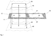
- FIG. 1 shows an arrangement of a first metal-ceramic substrate 10 and a second metal-ceramic substrate 20, with an orthogonal projection of the first metal-ceramic substrate 10 onto a projection plane 40, 40' parallel to the masked metal layer 11 of the first metal-ceramic -Substrate 10 shades the metal layer 21 of the second metal-ceramic substrate 20 to 0%.
- a first metal-ceramic substrate 10 is shown, which has a masked (not shown) metal layer 11 which is connected to a ceramic layer 12 .
- the ceramic layer 12 can have a larger dimension than the metal layer 11 and therefore go beyond the metal layer 11 .
- a second metal-ceramic substrate 20 having a metal layer 21 bonded to a ceramic layer 22 .
- the first metal-ceramic substrate 10 and the second metal-ceramic substrate 20 rest horizontally over their entire surface on a carrier 30 .
- a parallel displacement of the first metal-ceramic substrate 10 perpendicular to the metal layer 11 of the first metal-ceramic substrate 10 leads to an image 50, 50' of the first metal-ceramic substrate 10, which spans a projection plane 40, 40'.
- An orthogonal projection (indicated by broken arrows) of the first metal-ceramic substrate 10 onto the projection plane 40, 40' does not intersect the metal layer 21 of the second metal-ceramic substrate 20.
- the shading of the second metal-ceramic substrate 20 by an orthogonal projection of the first metal-ceramic substrate 10 onto a projection plane 40, 40' parallel to the metal layer 11 of the first metal-ceramic substrate 10 is therefore 0%.
- FIG. 2 shows an arrangement of a first metal-ceramic substrate 100 and a second metal-ceramic substrate 200, with an orthogonal projection of the first metal-ceramic substrate 100 onto a projection plane 400 parallel to the masked metal layer 110 of the first metal-ceramic substrate 100 the metal layer 210 of the second metal-ceramic substrate 200 shades by more than 60%.
- a first metal-ceramic substrate 100 is shown having a masked metal layer 110 (not shown) bonded to a ceramic layer 120 .
- a second metal-ceramic substrate 200 with a metal layer 210 which is connected to a ceramic layer 220.
- the first metal-ceramic substrate 100 and the second metal-ceramic substrate 200 are arranged obliquely on a carrier 300 (for example, a conveyor belt).
- the oblique arrangement can be achieved, for example, by means of a support (not shown).
- the second metal-ceramic substrate 200 is arranged behind the first metal-ceramic substrate 100 and is oriented parallel to it.
- a projection plane 400 is spaced parallel from the masked metal layer 110 of the first metal-ceramic substrate 100 .
- it can be spanned by the second metal-ceramic substrate 200 since this is arranged parallel to the masked metal layer 110 of the first metal-ceramic substrate 100 .
- the position of the projection plane is not further restricted.
- the projection plane can also be shifted parallel to the projection plane 400 shown here.
- it can be chosen such that it is at a greater distance from the metal surface 110 of the metal-ceramic substrate 100 than the projection surface 400 .
- the proportion of shading of the second metal-ceramic substrate 200 by an orthogonal projection of the first metal-ceramic substrate 100 onto a projection plane parallel to the metal layer 110 of the first metal-ceramic substrate 110 is independent of the exact position of the projection surface.
- An orthogonal projection (indicated by broken arrows) of the first metal-ceramic substrate 100 onto the projection plane 400 intersects the metal layer 210 of the second metal-ceramic substrate 200 in the hatched area 500.
- the shading of the second metal-ceramic substrate 200 by a Orthogonal projection of the first metal-ceramic substrate 100 onto a projection plane 400 parallel to the metal layer 110 of the first metal-ceramic substrate 100 is over 60%.
- an arrangement of the metal-ceramic substrates is advantageous that ensures that the surfaces of the metal-ceramic substrates with the unmasked areas (that is, for example, the areas not covered by an etching mask) are accessible to the etching solution 2 as freely as possible. Without wanting to be bound to a theory, this could be due to the fact that the unmasked areas can be ideally flown with the etching solution 2 . An effective flow of etching solution 2 could in turn result in the contacting with etching solution 2 already resulting in a complete removal of the active metal from the connecting layer within a very short period of time.
- the arrangement of the first metal-ceramic substrate and the second metal-ceramic substrate when contacted with the etching solution 2 is not further restricted.
- the first metal-ceramic substrate and the second metal-ceramic substrate are contacted with the etching solution 2 while the first metal-ceramic substrate and the second metal-ceramic substrate are moved.
- the movement is preferably a continuous movement.
- the first metal-ceramic substrate and the second metal-ceramic substrate for contacting with etching solution 2 are arranged on a carrier.
- the first metal-ceramic substrate and the second metal-ceramic substrate are particularly preferably arranged on the same carrier.
- the carrier can be a conveyor belt, for example.
- the carrier is a conveyor belt that is moved in a conveying direction.
- the carrier can also be a holder for metal-ceramic substrates, which rests on a conveyor belt.
- the first metal-ceramic substrate and the second metal-ceramic substrate can therefore, for example, be arranged directly on the conveyor belt as a carrier, or the first metal-ceramic substrate and the second metal-ceramic substrate can be arranged on another carrier (e.g a holder) can be arranged, which in turn is arranged on the conveyor belt as a carrier.
- another carrier e.g a holder
- first metal-ceramic substrate and the second metal-ceramic substrate on a carrier is not further restricted. According to a preferred embodiment, it is provided that the first metal-ceramic substrate and the second metal-ceramic substrate rest on one of the carriers over their entire surface. Alternatively, it can be provided that the first metal-ceramic substrate and the second metal-ceramic substrate rest essentially only on guide rails of a conveyor belt. According to a further alternative, the first metal-ceramic substrate and the second metal-ceramic substrate can rest on guide rails of a further carrier (for example a holder) or be clamped in a frame of a further carrier (for example a holder) and this Carrier can be arranged on a conveyor belt.
- a further carrier for example a holder
- this Carrier can be arranged on a conveyor belt.
- the metal-ceramic substrates are preferably on a carrier such that the metal layers of the first metal-ceramic substrate and of the second metal-ceramic substrate provided with the mask and preferably provided for the treatment with the etching solution 2 point away from the carrier .
- the first metal-ceramic substrate and the second metal-ceramic substrate are metal substrates metallized on both sides, with areas on the metal layers of the first metal-ceramic substrate and areas on the Metal layers of the second metal-ceramic substrate takes place.
- a configuration can be advantageous in which the metal-ceramic substrates for treatment with etching solution rest only at the edges on a carrier, for example on guide rails of a conveyor belt or on guide rails of a holder, or are clamped in a frame of a holder.
- the first metal-ceramic substrate and the second metal-ceramic substrate may not be stacked when contacting with etching solution 2 according to one embodiment.
- the first metal-ceramic substrate and the second metal-ceramic substrate are preferably arranged side by side.
- the first metal-ceramic substrate and the second metal-ceramic substrate are preferably arranged parallel to one another.
- the first metal-ceramic substrate and the second metal-ceramic substrate are arranged in a substantially horizontal position.
- the first metal-ceramic substrate and the second metal-ceramic substrate are preferably arranged side by side.
- the first metal-ceramic substrate and the second metal-ceramic substrate are preferably arranged parallel to one another.
- the first metal-ceramic substrate and the second metal-ceramic substrate can each be arranged lying on one of their metal layers, particularly preferably lying on the unmasked metal layer in each case.
- the first metal-ceramic substrate and the second metal-ceramic substrate are arranged in a substantially vertical position and one behind the other with respect to the conveying direction.
- the first metal-ceramic substrate and the second metal-ceramic substrate may be arranged in a holder on the conveyor belt, for example.
- the first metal-ceramic substrate and the second metal-ceramic substrate can be arranged in the same holder or the first metal-ceramic substrate and the second metal-ceramic substrate can be arranged in different holders.
- the first metal-ceramic substrate and the second metal-ceramic substrate are arranged one behind the other with respect to the conveying direction, so that an ideal flow of the etching solution 2 can take place.
- the first metal-ceramic substrate and the second metal-ceramic substrate are arranged such that the first metal-ceramic substrate and the conveying direction describe an angle of no more than 45°, more preferably no more than 30° and more preferably no more than 20°, and the second metal-ceramic substrate and the conveying direction describe an angle that is no more than 45°, more preferably no more than 30°, and even more preferably no more than 20°.
- the first metal-ceramic substrate and the second metal-ceramic substrate are arranged such that the first metal-ceramic substrate and the conveying direction describe an angle of at least 1°, more preferably at least 3° and particularly preferably at least 5°, and the second metal-ceramic substrate and the conveying direction describe an angle which is at least 1°, more preferably at least 3° and particularly preferably at least 5°.
- Such an angle between the first or second metal-ceramic substrate and the conveying direction of the conveyor belt can be favorable in order to make it easier for the etching solution 2 to run off.
- the first metal-ceramic substrate and the second metal-ceramic substrate are arranged such that the first metal-ceramic substrate and the conveying direction have an angle in the range of 1-45°, more preferably an angle in the range of 3-30° and more preferably an angle in the range of 5-20°, and the second metal-ceramic substrate and the conveying direction describe an angle in the range of 1-45°, more preferably an angle in the range of 3 - 30 ° and particularly preferably an angle in the range of 5 - describe 20 °.
- the process according to the invention is operated continuously.
- the type of contacting of the first metal-ceramic substrate and the second metal-ceramic substrate with the etching solution 2 is not further restricted.
- the first metal-ceramic substrate and the second metal-ceramic substrate are contacted with the etching solution 2 by spraying the first metal-ceramic substrate and the second metal-ceramic substrate with the etching solution 2, by immersing the first metal-ceramic substrate and the second metal-ceramic substrate in the etching solution 2; or by passing the first metal-ceramic substrate and the second metal-ceramic substrate through the etching solution 2.
- the first metal-ceramic substrate and the second metal-ceramic substrate are contacted with ultrasound during the contacting with the etching solution 2 .
- the masking is removed from the first metal-ceramic substrate and from the second metal-ceramic substrate.
- the masking can be removed from the first metal-ceramic substrate and the second metal-ceramic substrate after contacting with etching solution 2 .
- the masking is not further restricted and can be removed in a manner known to the person skilled in the art.
- the first metal-ceramic substrate and the second metal-ceramic substrate are preferably dried.
- a metal-ceramic substrate obtained by the method described above has particularly fine structures and is outstandingly suitable for use in power electronics.
- tin powder 7.8 percent by weight of tin powder (7-11 ⁇ m), 3.7 percent by weight of titanium hydride and 6.5 percent by weight of an organic vehicle were first mixed in a stand mixer at 1930 rpm for 30 minutes. Thereafter, 3.0% by weight of Texanol and 67% by weight of copper powder (7-11 ⁇ m) were added in increments. The received Mixture was stirred at high speed until a homogeneous paste was obtained.
- ceramic bodies were bonded to metal foils on both sides of their opposite surfaces.
- ceramic bodies with the dimensions 174 ⁇ 139 ⁇ 0.32 mm (obtained from Toshiba Materials) were used, which had an identical front and rear side configuration.
- the paste was screen-printed onto the back of the ceramic bodies using a 280-mesh screen over an area measuring 168 ⁇ 130 mm and pre-dried at 125° C. for 15 minutes.
- the paste thickness after pre-drying was 25 +/- 5 ⁇ m.
- a copper foil made of oxygen-free, highly conductive copper with a purity of 99.99% and dimensions of 170 ⁇ 132 ⁇ 0.3 mm was then placed on the pre-dried paste.
- the assembly thus produced was turned over, the paste was similarly printed on the front of the ceramic body, pre-dried and fitted with a copper foil to obtain a sandwich assembly. Then, the sandwich assembly was loaded with a silicon carbide plate weighing 1 kg, fired at a peak temperature of 910°C (measured by a thermocouple) for 20 minutes, and then cooled to room temperature to obtain a metal-ceramic substrate, the one Contained ceramic layer, which was connected on both sides with a copper layer via a connecting layer.
- the metal-ceramic substrates obtained according to the above production example were provided with an etching mask with masked and unmasked areas on the upper side. After washing with water, the metal-ceramic substrates were treated with an etching solution 1 to remove copper from the copper layer and copper and tin from the connection layer. Subsequently, the metal-ceramic substrates were washed and treated with Etching Solution 2 to remove titanium from the bonding layer according to Examples and Comparative Examples below.
- the metal-ceramic substrates were placed on a conveyor in a horizontal position, and conveyed through an Etching Solution 2 bath by the conveyor.
- the metal-ceramic substrates were placed on a conveyor in a horizontal position, and conveyed by the conveyor through a bath of etching solution 2 while being treated with ultrasound.
- the metal-ceramic substrates were placed in a horizontal position on a conveyor belt and passed under spray nozzles, from which Etching Solution 2 was sprayed onto the metal-ceramic substrates.
- the metal-ceramic substrates were placed on a conveyor in a horizontal position, and sprayed with an etching solution 2 in a stationary state.
- the metal-ceramic substrates were placed on a conveyor belt and conveyed with the conveyor belt through a bath of etching solution 2 while being treated with ultrasound.
- the metal-ceramic substrates and the conveying direction of the conveyor belt each described an angle of 15°.
- the inclined positioning of the metal-ceramic substrates was achieved with a support.
- the metal-ceramic substrates were arranged in such a way that an orthogonal projection of a metal-ceramic substrate onto a projection plane parallel to the masked metal layer of this metal-ceramic substrate shaded the metal layer of another (adjacent) metal-ceramic substrate by no more than 15%.
- the metal-ceramic substrates were placed on a conveyor belt and conveyed with the conveyor belt through a bath of etching solution 2 while being treated with ultrasound.
- the metal-ceramic substrates and the conveying direction of the conveyor belt each described an angle of 10°.
- the inclined positioning of the metal-ceramic substrates was achieved with a support.
- the metal-ceramic substrates were arranged so that an orthogonal projection of a metal-ceramic substrate onto a projection plane parallel to the masked metal layer, this metal-ceramic substrate shaded the metal layer of another (adjacent) metal-ceramic substrate by at most 50%.
- the metal-ceramic substrates were placed in a vertical position in a holder on a conveyor belt, and conveyed through an Etching Solution 2 bath by the conveyor belt.
- the metal-ceramic substrates were placed in a vertical position in a holder on a conveyor belt, and conveyed by the conveyor belt through a bath of etching solution 2 while being treated with ultrasound.
- the metal-ceramic substrates were placed in a vertical position in a holder on a conveyor belt and passed under spray nozzles, from which Etching Solution 2 was sprayed onto the metal-ceramic substrates.
- the metal-ceramic substrates were placed in a vertical position in a holder on a conveyor belt and sprayed with an etching solution 2 in a stationary state.
- the metal-ceramic substrates were placed on a conveyor belt and conveyed with the conveyor belt through a bath of etching solution 2 while being treated with ultrasound.
- the metal-ceramic substrates and the conveying direction of the conveyor belt each described an angle of 10°.
- the inclined positioning of the metal-ceramic substrates was achieved with a support.
- the metal-ceramic substrates were arranged in such a way that an orthogonal projection of a metal-ceramic substrate onto a projection plane parallel to the masked metal layer of this metal-ceramic substrate shadowed the metal layer of another (adjacent) metal-ceramic substrate by 70%.
- the results show that a particularly effective removal of the active metal can be achieved if, when making contact with etching solution 2, the metal-ceramic substrates are arranged in such a way that an orthogonal projection of a metal-ceramic substrate onto a projection plane parallel to the metal layer of this metal Ceramic substrate does not shade the metal layer of another metal-ceramic substrate by more than 60%, as is the case, for example, with a horizontal or almost horizontal position of the metal-ceramic substrates in which they are isolated.
- the results also show that the free active metal is practically completely removed in a metal-ceramic substrate obtained by the process according to the invention.
Abstract
Die Erfindung betrifft ein Verfahren zur Strukturierung von Metall-Keramik-Substraten sowie ein strukturiertes Metall-Keramik-Substrat, das insbesondere in der Leistungselektronik zum Einsatz kommen kann. Bei dem Verfahren werden ein erstes Metall-Keramik-Substrat und ein zweites Metall-Keramik-Substrat geätzt, wobei bei der Kontaktierung mit einer Ätzlösung, die in der Lage ist, Aktivmetall aus der Verbindungsschicht der Metall-Keramik-Substrate abzutragen, das erste Metall-Keramik-Substrat und das zweite Metall-Keramik-Substrat so angeordnet sind, dass eine Orthogonalprojektion des ersten Metall-Keramik-Substrats auf eine Projektionsebene parallel zur Metallschicht des ersten Metall-Keramik-Substrats die Metallschicht des zweiten Metall-Keramik-Substrats zu nicht mehr als 60% abschattet.

Description
Die vorliegende Erfindung betrifft ein Verfahren zur Strukturierung von Metall-Keramik-Substraten sowie ein strukturiertes Metall-Keramik-Substrat.The present invention relates to a method for structuring metal-ceramic substrates and a structured metal-ceramic substrate.
Metall-Keramik-Substrate spielen eine wichtige Rolle im Bereich der Leistungselektronik. Sie sind ein maßgebliches Element beim Aufbau von elektronischen Bauteilen und sorgen für eine schnelle Ableitung hoher Wärmemengen beim Betrieb dieser Bauteile. Metall-Keramik-Substrate bestehen üblicherweise aus einer Keramikschicht und einer Metallschicht, die mit der Keramikschicht verbunden ist.Metal-ceramic substrates play an important role in the field of power electronics. They are a key element in the construction of electronic components and ensure that large amounts of heat are quickly dissipated when these components are in operation. Metal-ceramic substrates usually consist of a ceramic layer and a metal layer bonded to the ceramic layer.
Zur Verbindung der Metallschicht mit der Keramikschicht sind aus dem Stand der Technik mehrere Verfahren bekannt. Beim sogenannten DCB ("Direct Copper Bonding") -Verfahren wird eine Kupferfolie durch Reaktion von Kupfer mit einem Reaktivgas (üblicherweise Sauerstoff) oberflächlich mit einer Kupferverbindung (üblicherweise Kupferoxid) versehen, die einen niedrigeren Schmelzpunkt als Kupfer aufweist. Wenn die so behandelte Kupferfolie auf einen Keramikkörper aufgebracht und der Verbund gebrannt wird, schmilzt die Kupferverbindung und benetzt die Oberfläche des Keramikkörpers, so dass es zu einer stabilen stoffschlüssigen Verbindung zwischen der Kupferfolie und dem Keramikkörper kommt. Dieses Verfahren ist zum Beispiel in der
Trotz offensichtlicher Vorteile weist das DCB-Verfahren zwei Hauptnachteile auf. Erstens muss das Verfahren bei relativ hohen Temperaturen durchgeführt werden, nämlich etwas unterhalb des Schmelzpunktes von Kupfer. Zweitens kann das Verfahren nur für Keramiken auf Aluminiumbasis wie Aluminiumoxid oder Aluminiumnitrid verwendet werden. Daher besteht ein Bedarf an einem alternativen Verfahren zur Herstellung von Metall-Keramik-Substraten unter weniger strengen Bedingungen. In einem alternativen Verfahren können Metallfolien bei Temperaturen von etwa 650 bis 1000°C mit Keramikkörpern verbunden werden, wobei ein spezielles Lot verwendet wird, das üblicherweise Silber und/oder Kupfer und ein Aktivmetall enthält. Die Rolle des Aktivmetalls besteht darin, mit dem Keramikmaterial zu reagieren und so eine Verbindung des Keramikmaterials mit dem übrigen Lot unter Bildung einer Reaktionsschicht zu ermöglichen, während das Kupfer und/oder Silber zur Verbindung dieser Reaktionsschicht mit der Metallfolie dient. So schlägt zum Beispiel die
Nach der Verbindung der Metallfolie mit dem Keramikkörper wird das entstandene Metall-Keramik-Substrat üblicherweise zum Aufbau von Leiterbahnen strukturiert. Hierzu werden in der Regel herkömmliche Ätztechniken eingesetzt. Gemäß einem gängigen Verfahren wird die Metalloberfläche des Metall-Keramik-Substrats mit einer Maskierung, zum Beispiel mit einem Polymer, versehen. Durch diese Maskierung werden diejenigen Stellen des Metall-Keramik-Substrats, die im folgenden Ätzschritt nicht entfernt werden sollen, geschützt, währen die unmaskierten Stellen für eine Ätzung zugänglich sind. Bei der Ätzung werden dann durch Verwendung mehrerer Ätzlösungen das Metall der Metallfolie und die Bestandteile der Verbindungsschicht in Lösung gebracht und vom Metall-Keramik-Substrat entfernt, wodurch Leiterbahnen entstehen. Anschließend wird die Maskierung entfernt, wodurch ein strukturiertes Metall-Keramik-Substrat enthalten wird.After the metal foil has been connected to the ceramic body, the resulting metal-ceramic substrate is usually structured in order to build up conductor tracks. Conventional etching techniques are generally used for this purpose. According to a common method, the metal surface of the metal-ceramic substrate is provided with a mask, for example with a polymer. This masking protects those areas of the metal-ceramic substrate that are not to be removed in the subsequent etching step, while the unmasked areas are accessible for etching. During the etching, the metal of the metal foil and the components of the connecting layer are dissolved and removed from the metal-ceramic substrate by using several etching solutions, whereby conductor tracks are formed. The masking is then removed, resulting in a patterned metal-ceramic substrate.
Gemäß einem herkömmlichen Verfahren werden bei der Behandlung mit einer ersten Ätzlösung das Metall der Metallfolie sowie Bestandteile des Lots der Verbindungsschicht entfernt, wobei wenigstens das Aktivmetall übrig bleibt. Das Aktivmetall wird anschließend durch Behandlung mit einer zweiten Ätzlösung in Lösung gebracht und entfernt. Um einen möglichst hohen Durchsatz zu erreichen, werden die Metall-Keramik-Substrate üblicherweise in einer Haltevorrichtung gestapelt und in der Haltevorrichtung mit den Ätzlösungen kontaktiert. Dabei hat sich das vertikale Stapeln der Metall-Keramik-Substrate aus Praktikabilitätsgründen als besonders vorteilhaft erwiesen. Um eine vollständige Ätzung zu gewährleisten, müssen die Metall-Keramik-Substrate längere Zeit mit den Ätzlösungen kontaktiert werden.According to a conventional method, the metal of the metal foil and components of the solder of the connecting layer are removed during treatment with a first etching solution, with at least the active metal remaining. The active metal is then dissolved and removed by treatment with a second etching solution. In order to achieve the highest possible throughput, the metal-ceramic substrates are usually stacked in a holding device and contacted with the etching solutions in the holding device. The vertical stacking of the metal-ceramic substrates has proven to be particularly advantageous for reasons of practicability. In order to ensure complete etching, the metal-ceramic substrates must be in contact with the etching solutions for a longer period of time.
Grundsätzlich besteht der Bedarf, die Verweilzeit der Metall-Keramik-Substrate in den Ätzlösungen zu reduzieren. Damit ließe sich das Verfahren zur Strukturierung von Metall-Keramik-Substraten schneller, effizienter, ressourcenschonender und energieschonender durchführen. Ferner besteht der Bedarf, innerhalb einer vorgegebenen Zeit einen möglichst vollständigen Abtrag des beim Ätzen zu entfernenden Materials, insbesondere des Aktivmetalls, zu erreichen.Basically, there is a need to reduce the dwell time of the metal-ceramic substrates in the etching solutions. This would allow the process for structuring metal-ceramic substrates to be carried out faster, more efficiently, with less use of resources and less energy. Furthermore, there is a need to achieve as complete a removal as possible of the material to be removed during etching, in particular the active metal, within a predetermined time.
Die vorliegende Erfindung stellt sich daher die Aufgabe, ein einfaches Verfahren zur Strukturierung von Metall-Keramik-Substraten bereitzustellen. Vorzugsweise soll dieses Verfahren schneller, effizienter, ressourcenschonender und/oder energieschonender sein als die aus dem Stand der Technik bekannten Verfahren. Ferner ist es bevorzugt, dass das Verfahren in einer vorgegebenen Zeit zu einem möglichst vollständigen Abtrag des beim Ätzen zu entfernenden Materials, insbesondere des Aktivmetalls, führt.The object of the present invention is therefore to provide a simple method for structuring metal-ceramic substrates. This method should preferably be faster, more efficient, more resource-saving and/or energy-saving than the methods known from the prior art. Furthermore, it is preferred that the method leads to the most complete possible removal of the material to be removed during etching, in particular the active metal, within a predetermined time.
Diese Aufgabe wird gelöst durch das Verfahren von Anspruch 1.This object is solved by the method of claim 1.
Die Erfindung stellt daher ein Verfahren zur Strukturierung von Metall-Keramik-Substraten bereit, umfassend die Schritte:
- a) Bereitstellung eines ersten Metall-Keramik-Substrats und eines zweiten Metall-Keramik-Substrats, jeweils aufweisend
- eine Keramikschicht,
- eine Metallschicht und
- eine Verbindungsschicht, die sich zwischen der Keramikschicht und der Metallschicht befindet, wobei die Verbindungsschicht (i) ein Metall mit einem Schmelzpunkt von wenigstens 700°C und (ii) ein Aktivmetall aufweist,
- b) Bereitstellung einer Ätzlösung 1, die in der Lage ist, das Metall aus der Metallschicht und wenigstens teilweise das Metall mit einem Schmelzpunkt von wenigstens 700°C aus der Verbindungsschicht abzutragen,
- c) Bereitstellung einer
Ätzlösung 2, die in der Lage ist, das Aktivmetall aus der Verbindungsschicht abzutragen, - d) Maskierung von Bereichen auf der Metallschicht des ersten Metall-Keramik-Substrats und auf der Metallschicht des zweiten Metall-Keramik-Substrats, die nicht für das Abtragen vorgesehen sind,
- e) Kontaktierung des ersten Metall-Keramik-Substrats und des zweiten Metall-Keramik-Substrats mit der Ätzlösung 1 und
- f) Kontaktierung des ersten Metall-Keramik-Substrats und des zweiten Metall-Keramik-Substrats mit der
Ätzlösung 2, wobei das erste Metall-Keramik-Substrat und das zweite Metall-Keramik-Substrat so angeordnet sind, dass eine Orthogonalprojektion des ersten Metall-Keramik-Substrats auf eine Projektionsebene parallel zur Metallschicht des ersten Metall-Keramik-Substrats die Metallschicht des zweiten Metall-Keramik-Substrats zu nicht mehr als 60% abschattet.
- a) providing a first metal-ceramic substrate and a second metal-ceramic substrate, each having
- a ceramic layer,
- a metal layer and
- a bonding layer located between the ceramic layer and the metal layer, the bonding layer comprising (i) a metal having a melting point of at least 700°C and (ii) an active metal,
- b) providing an etching solution 1 capable of removing the metal from the metal layer and at least partially removing the metal with a melting point of at least 700° C. from the connecting layer,
- c) providing an
etching solution 2 which is capable of removing the active metal from the connecting layer, - d) masking of areas on the metal layer of the first metal-ceramic substrate and on the metal layer of the second metal-ceramic substrate that are not intended for removal,
- e) contacting the first metal-ceramic substrate and the second metal-ceramic substrate with the etching solution 1 and
- f) contacting of the first metal-ceramic substrate and the second metal-ceramic substrate with the
etching solution 2, wherein the first metal-ceramic substrate and the second metal-ceramic substrate are arranged such that an orthogonal projection of the first metal Ceramic substrate on a projection plane parallel to the metal layer of the first metal-ceramic substrate shades the metal layer of the second metal-ceramic substrate to no more than 60%.
Ferner stellt die Erfindung ein Metall-Keramik-Substrat bereit, das durch dieses Verfahren erhältlich ist.Furthermore, the invention provides a metal-ceramic substrate obtainable by this method.
Das erfindungsgemäße Verfahren betrifft die Strukturierung von Metall-Keramik-Substraten.The method according to the invention relates to the structuring of metal-ceramic substrates.
Dazu werden zunächst ein erstes Metall-Keramik-Substrat und ein zweites Metall-Keramik-Substrat bereitgestellt.For this purpose, a first metal-ceramic substrate and a second metal-ceramic substrate are initially provided.
Das erste und das zweite Metall-Keramik-Substrat weisen jeweils eine Metallschicht auf. Das Metall der Metallschicht ist vorzugsweise aus der Gruppe ausgewählt, die aus Kupfer, Aluminium und Molybdän besteht. Gemäß einer besonders bevorzugten Ausführungsform ist das Metall der Metallschicht aus der Gruppe ausgewählt, die aus Kupfer und Molybdän besteht. Gemäß einer ganz besonders bevorzugten Ausführungsform ist das Metall der Metallschicht Kupfer. Die Metallschicht weist vorzugsweise eine Dicke im Bereich von 0,01 - 10 mm, mehr bevorzugt im Bereich von 0,03 - 5 mm und besonders bevorzugt im Bereich von 0,05 - 3 mm auf.The first and the second metal-ceramic substrate each have a metal layer. The metal of the metal layer is preferably selected from the group consisting of copper, aluminum and molybdenum. According to a particularly preferred embodiment, the metal of the metal layer is selected from the group consisting of copper and molybdenum. According to a very particularly preferred embodiment, the metal of the metal layer is copper. The metal layer preferably has a thickness in the range of 0.01-10 mm, more preferably in the range of 0.03-5 mm and particularly preferably in the range of 0.05-3 mm.
Das erste und das zweite Metall-Keramik-Substrat weisen jeweils eine Keramikschicht auf. Die Keramik der Keramikschicht ist vorzugsweise eine isolierende Keramik. Bei der Keramik kann es sich beispielsweise um eine Oxidkeramik, eine Nitridkeramik oder eine Carbidkeramik handeln. Vorzugsweise handelt es sich bei der Keramik um eine Metalloxidkeramik, eine Siliziumoxidkeramik, eine Metallnitridkeramik, eine Siliziumnitridkeramik, eine Bornitridkeramik oder eine Borcarbidkeramik. Gemäß einer bevorzugten Ausführungsform ist die Keramik aus der Gruppe ausgewählt, die aus Aluminiumnitridkeramiken, Siluziumnitridkeramiken und Aluminiumoxidkeramiken (wie zum Beispiel ZTA ("Zirconia Toughened Alumina") -Keramiken) besteht. Die Keramikschicht weist vorzugsweise eine Dicke von 0,05 - 10 mm, mehr bevorzugt im Bereich von 0,1 - 5 mm und noch mehr bevorzugt im Bereich von 0,15 - 3 mm auf.The first and the second metal-ceramic substrate each have a ceramic layer. The ceramic of the ceramic layer is preferably an insulating ceramic. The ceramic can be, for example, an oxide ceramic, a nitride ceramic or a carbide ceramic. The ceramic is preferably a metal oxide ceramic, a silicon oxide ceramic, a metal nitride ceramic, a silicon nitride ceramic, a boron nitride ceramic or a boron carbide ceramic. According to a preferred embodiment, the ceramic is selected from the group consisting of aluminum nitride ceramics, silicon nitride ceramics and aluminum oxide ceramics (such as example ZTA ("Zirconia Toughened Alumina") ceramics). The ceramic layer preferably has a thickness of 0.05 - 10 mm, more preferably in the range of 0.1 - 5 mm and even more preferably in the range of 0.15 - 3 mm.
Das erste Metall-Keramik-Substrat und das zweite Metall-Keramik-Substrat weisen jeweils eine Verbindungsschicht auf, die sich zwischen der Keramikschicht und der Metallschicht befindet. Die Verbindungsschicht stellt vorzugsweise eine stoffschlüssige Verbindung zwischen der Keramikschicht und der Metallschicht her.The first metal-ceramic substrate and the second metal-ceramic substrate each have a bonding layer located between the ceramic layer and the metal layer. The connecting layer preferably creates a material connection between the ceramic layer and the metal layer.
Die Verbindungsschicht weist (i) ein Metall mit einem Schmelzpunkt von wenigstens 700°C und (ii) ein Aktivmetall auf. Das Metall mit einem Schmelzpunkt von wenigstens 700°C weist vorzugsweise einen Schmelzpunkt von wenigstens 850°C und mehr bevorzugt einen Schmelzpunkt von wenigstens 1000°C auf. Gemäß einer bevorzugten Ausführungsform ist das Metall mit einem Schmelzpunkt von wenigstens 700°C aus der Gruppe ausgewählt, die aus Kupfer, Silber, Nickel, Wolfram, Molybdän und Mischungen davon besteht. Gemäß einer besonders bevorzugten Ausführungsform ist das Metall mit einem Schmelzpunkt von wenigstens 700°C aus der Gruppe ausgewählt, die aus Kupfer, Nickel, Wolfram, Molybdän und Mischungen davon besteht. Gemäß einer ganz besonders bevorzugten Ausführungsform ist das Metall mit einem Schmelzpunkt von wenigstens 700°C Kupfer. Der Gehalt an dem wenigstens einen Metall mit einem Schmelzpunkt von wenigstens 700°C beträgt vorzugsweise 55 - 93 Atomprozent, besonders bevorzugt 60 - 85 Atomprozent und ganz besonders bevorzugt 65 - 80 Atomprozent, bezogen auf die Anzahl an Atomen in der Verbindungsschicht.The bonding layer comprises (i) a metal having a melting point of at least 700°C and (ii) an active metal. The metal having a melting point of at least 700°C preferably has a melting point of at least 850°C and more preferably has a melting point of at least 1000°C. In a preferred embodiment, the metal having a melting point of at least 700°C is selected from the group consisting of copper, silver, nickel, tungsten, molybdenum, and mixtures thereof. According to a particularly preferred embodiment, the metal having a melting point of at least 700°C is selected from the group consisting of copper, nickel, tungsten, molybdenum and mixtures thereof. According to a most preferred embodiment, the metal having a melting point of at least 700°C is copper. The content of the at least one metal having a melting point of at least 700°C is preferably 55-93 atomic percent, more preferably 60-85 atomic percent, and most preferably 65-80 atomic percent based on the number of atoms in the bonding layer.
Das Aktivmetall ist vorzugweise aus der Gruppe ausgewählt, die aus Titan, Zirkonium, Niob, Tantal, Vanadium, Hafnium und Mischungen davon besteht. Gemäß einer besonders bevorzugten Ausführungsform ist das Aktivmetall Titan. Der Gehalt an dem Aktivmetall beträgt vorzugsweise 1 - 10 Atomprozent, besonders bevorzugt 2 - 8 Atomprozent und ganz besonders bevorzugt 3 - 7 Atomprozent, bezogen auf die Anzahl an Atomen in der Verbindungsschicht.The active metal is preferably selected from the group consisting of titanium, zirconium, niobium, tantalum, vanadium, hafnium, and mixtures thereof. According to a particularly preferred embodiment, the active metal is titanium. The content of the active metal is preferably 1 - 10 atomic percent, more preferably 2 - 8 atomic percent, and most preferably 3 - 7 atomic percent based on the number of atoms in the bonding layer.
Die Verbindungsschicht kann gemäß einer bevorzugten Ausführungsform neben (i) einem Metall mit einem Schmelzpunkt von wenigstens 700°C und ii) einem Aktivmetall zusätzlich (iii) weitere Elemente als Rest aufweisen. Gemäß einer besonders bevorzugten Ausführungsform beträgt der Gehalt an weiteren Elementen in der Verbindungsschicht 5 - 40 Atomprozent, mehr bevorzugt 7 - 35 Atomprozent und besonders bevorzugt 10 - 35 Atomprozent, bezogen auf die Anzahl an Atomen in der Verbindungsschicht.According to a preferred embodiment, in addition to (i) a metal having a melting point of at least 700° C. and ii) an active metal, the connecting layer can additionally have (iii) further elements as a remainder. According to a particularly preferred embodiment, the content of further elements in the connecting layer is 5 - 40 atomic percent, more preferably 7-35 atomic percent, and most preferably 10-35 atomic percent based on the number of atoms in the tie layer.
So weist die Verbindungsschicht gemäß einer weiteren bevorzugten Ausführungsform ein Metall mit einem Schmelzpunkt von weniger als 700°C auf. Das Metall mit einem Schmelzpunkt von weniger als 700°C weist vorzugsweise einen Schmelzpunkt von weniger als 600°C und besonders bevorzugt einen Schmelzpunkt von weniger als 550°C auf. Gemäß einer bevorzugten Ausführungsform ist das Metall mit einem Schmelzpunkt von weniger als 700°C aus der Gruppe ausgewählt, die aus Zinn, Bismut, Indium, Gallium, Zink, Antimon, Magnesium und Mischungen davon besteht. Gemäß einer besonders bevorzugten Ausführungsform ist das Metall mit einem Schmelzpunkt von weniger als 700°C aus der Gruppe ausgewählt, die aus Zinn, Bismut und Mischungen davon besteht. Der Gehalt an dem wenigstens einen Metall mit einem Schmelzpunkt von weniger als 700°C beträgt vorzugsweise 5-40 Atomprozent, mehr bevorzugt 7 - 35 Atomprozent und besonders bevorzugt 10 - 35 Atomprozent, bezogen auf die Anzahl an Atomen in der Verbindungsschicht.Thus, according to a further preferred embodiment, the connecting layer has a metal with a melting point of less than 700°C. The metal having a melting point of less than 700°C preferably has a melting point of less than 600°C and more preferably has a melting point of less than 550°C. In a preferred embodiment, the metal having a melting point less than 700°C is selected from the group consisting of tin, bismuth, indium, gallium, zinc, antimony, magnesium and mixtures thereof. According to a particularly preferred embodiment, the metal having a melting point of less than 700°C is selected from the group consisting of tin, bismuth and mixtures thereof. The content of the at least one metal having a melting point lower than 700°C is preferably 5-40 atomic percent, more preferably 7-35 atomic percent, and particularly preferably 10-35 atomic percent based on the number of atoms in the bonding layer.
Gemäß einer bevorzugten Ausführungsform weist die Verbindungsschicht einen metallschichtnahen Bereich und einen keramikschichtnahen Bereich auf. Der metallschichtnahe Bereich ist vorzugsweise reicher an dem Metall mit einem Schmelzpunkt von wenigstens 700°C als der keramikschichtnahe Bereich. Der keramikschichtnahe Bereich ist vorzugsweise reicher an Aktivmetall als der metallschichtnahe Bereich. Gemäß einer besonders bevorzugten Ausführungsform ist der metallschichtnahe Bereich dicker als der keramikschichtnahe Bereich der Verbindungsschicht. Dabei kann es bevorzugt sein, dass das Verhältnis der Dicke des metallschichtnahen Bereichs der Verbindungsschicht zur Dicke des keramikschichtnahen Bereichs der Verbindungsschicht wenigstens 2 : 1, noch mehr bevorzugt wenigstens 3 : 1 und besonders bevorzugt wenigstens 5 : 1 beträgt.According to a preferred embodiment, the connecting layer has an area close to the metal layer and an area close to the ceramic layer. The area close to the metal layer is preferably richer in the metal with a melting point of at least 700° C. than the area close to the ceramic layer. The area close to the ceramic layer is preferably richer in active metal than the area close to the metal layer. According to a particularly preferred embodiment, the area close to the metal layer is thicker than the area of the connecting layer close to the ceramic layer. It can be preferred that the ratio of the thickness of the area of the connecting layer close to the metal layer to the thickness of the area of the connecting layer close to the ceramic layer is at least 2:1, more preferably at least 3:1 and particularly preferably at least 5:1.
Gemäß einer bevorzugten Ausführungsform liegt der maximale Gehalt an Silber vorzugsweise bei 15,0 Atomprozent, mehr bevorzugt bei 1,0 Atomprozent, noch mehr bevorzugt bei 0,5 Atomprozent und ganz besonders bevorzugt bei 0,1 Atomprozent, bezogen auf die Anzahl an Atomen in der Verbindungsschicht. Demnach kann es bevorzugt sein, dass die Verbindungsschicht silberfrei oder silberarm ist. Überraschenderweise hat sich gezeigt, dass ein Fehlen von Silber in der Verbindungsschicht oder ein nur geringer Gehalt von Silber in der Verbindungsschicht dazu führt, dass mit dem erfindungsgemäßen Verfahren in kürzerer Zeit ein zuverlässiger und vollständiger Abtrag des Aktivmetalls aus dem zu ätzenden Bereich der Verbindungsschicht erreicht werden kann. Ohne an eine Theorie gebunden sein zu wollen, könnte dieser Effekt darauf zu rückzuführen sein, dass die Gegenwart von Silber die Ausbildung eines metallschichtnahen Bereichs begünstigt, der durch Ätzen nur schwer zu entfernen ist. Die Bildung dieses silberhaltigen metallschichtnahen Bereichs könnte schließlich dazu führen, dass die Kontaktierung des aktivmetallhaltigen keramikschichtnahen Bereichs mit der Ätzlösung 2 wirksam blockiert wird. Diese Blockierung würde durch die Reduktion eines Anteils an Silber in der Verbindungsschicht vermindert oder sogar aufgehoben werden, so dass eine leichtere Entfernbarkeit des Aktivmetalls die Folge ist.According to a preferred embodiment, the maximum content of silver is preferably 15.0 atomic percent, more preferably 1.0 atomic percent, even more preferably 0.5 atomic percent and most preferably 0.1 atomic percent, based on the number of atoms in the connection layer. Accordingly, it can be preferred that the connecting layer is silver-free or low-silver. Surprisingly, it has been shown that a lack of silver in the connecting layer or only a low silver content in the connecting layer means that the method according to the invention results in reliable and complete removal of the active metal in a shorter time can be achieved in the area of the connection layer to be etched. Without wanting to be bound to a theory, this effect could be attributed to the fact that the presence of silver promotes the formation of a region close to the metal layer that is difficult to remove by etching. The formation of this area close to the silver-containing metal layer could ultimately lead to the contacting of the area close to the active metal-containing ceramic layer with the
Gemäß einer bevorzugten Ausführungsform weisen das erste Metall-Keramik-Substrat und das zweite Metall-Keramik-Substrat jeweils auf
- eine zweite Metallschicht und
- eine zweite Verbindungsschicht, die sich zwischen der Keramikschicht und der zweiten Metallschicht befindet, wobei die zweite Verbindungsschicht (i) ein Metall mit einem Schmelzpunkt von wenigstens 700°C und (ii) ein Aktivmetall aufweist.
- a second metal layer and
- a second bonding layer located between the ceramic layer and the second metal layer, the second bonding layer comprising (i) a metal having a melting point of at least 700°C and (ii) an active metal.
Derartige Metall-Keramik-Substrate werden auch doppelseitig metallisierte Metall-Keramik-Substrate genannt. Zu den Merkmalen der zweiten Metallschicht und der zweiten Verbindungsschicht kann auf die hierin beschriebenen Ausführungen zur Metallschicht und zur Verbindungsschicht Bezug genommen werden. Vorzugsweise sind demnach die zweite Metallschicht wie die hierin beschriebene Metallschicht und die zweite Verbindungsschicht wie die hierin beschriebene Verbindungsschicht ausgebildet.Such metal-ceramic substrates are also called metal-ceramic substrates metallized on both sides. Regarding the features of the second metal layer and the second connection layer, reference can be made to the statements regarding the metal layer and the connection layer described herein. Accordingly, the second metal layer is preferably embodied like the metal layer described herein, and the second connecting layer is embodied like the connecting layer described herein.
Die Metall-Keramik-Substrate können durch ein herkömmliches und aus dem Stand der Technik bekanntes Verfahren hergestellt werden. Vorzugsweise werden die Metall-Keramik-Substrate mittels eines Lötverfahrens hergestellt. Gemäß einer bevorzugten Ausführungsform erfolgt die Herstellung der Metall-Keramik-Substrate durch ein AMB ("Active Metal Brazing") -Verfahren. Bei diesem Verfahren wird üblicherweise eine Metallfolie mit einem Keramikkörper unter Verwendung eines Lotmaterials verlötet, das Kupfer, Silber und ein Aktivmetall (zum Beispiel Titan) aufweist. Ein solches Verfahren ist zum Beispiel in der
In dem erfindungsgemäßen Verfahren wird eine Ätzlösung 1 bereitgestellt, die in der Lage ist, das Metall der Metallschicht und wenigstens teilweise das Metall mit einem Schmelzpunkt von wenigstens 700°C aus der Verbindungsschicht abzutragen. Bei der Ätzlösung 1 kann es sich zum Beispiel um eine aus dem Stand der Technik bekannte und für die Ätzung von Kupfer geeignete Ätzlösung handeln. Ätzlösung 1 kann daher zum Beispiel aus der Gruppe ausgewählt sein, die aus FeCl3-Ätzlösungen und CuCl2-Ätzlösungen besteht.In the method according to the invention, an etching solution 1 is provided which is able to remove the metal of the metal layer and at least partially the metal with a melting point of at least 700° C. from the connecting layer. Etching solution 1 can be, for example, an etching solution known from the prior art and suitable for etching copper. Etching solution 1 can therefore be selected, for example, from the group consisting of FeCl 3 etching solutions and CuCl 2 etching solutions.
In dem erfindungsgemäßen Verfahren wird ferner eine Ätzlösung 2 bereitgestellt, die in der Lage ist, das Aktivmetall aus der Verbindungsschicht abzutragen. Bei der Ätzlösung 2 kann es sich um eine aus dem Stand der Technik bekannte Ätzlösung für Aktivmetalle handeln. Beispielhafte Ätzlösungen sind in der
Erfindungsgemäß erfolgt eine Maskierung von Bereichen auf dem ersten Metall-Keramik-Substrat und dem zweiten Metall-Keramik-Substrat, die nicht für das Abtragen vorgesehen sind. Die Maskierung ist nicht weiter eingeschränkt und kann auf eine dem Fachmann aus dem Stand der Technik bekannte Weise erfolgen. Für die Maskierung kann zum Beispiel ein Ätzresist verwendet werden. So ist es zum Beispiel möglich, einen Ätzresist auf die Metallschicht des Metall-Keramik-Substrats aufzubringen und zur Aushärtung nur die Bereiche zu belichten, die nicht für das Abtragen vorgesehen sind. Bei der anschließenden Kontaktierung mit den Ätzlösungen sind die maskierten Bereiche geschützt, so dass in diesen Bereichen kein Materialabtrag durch die Einwirkung der Ätzlösungen erfolgt. Dagegen sind die unmaskierten (nicht ausgehärteten) Bereiche im nachfolgenden Ätzschritt für die Ätzung zugänglich.According to the invention, regions on the first metal-ceramic substrate and the second metal-ceramic substrate that are not intended for removal are masked. The masking is not further restricted and can be carried out in a manner known to a person skilled in the art from the prior art. An etch resist, for example, can be used for the masking. For example, it is possible to apply an etching resist to the metal layer of the metal-ceramic substrate and only expose the areas that are not intended for removal for curing. During the subsequent contacting with the etching solutions, the masked areas are protected so that no material is removed in these areas by the action of the etching solutions. In contrast, the unmasked (uncured) areas are accessible for etching in the subsequent etching step.
Gemäß der vorliegenden Erfindung erfolgt anschließend eine Kontaktierung des ersten Metall-Keramik-Substrats und des zweiten Metall-Keramik-Substrats mit der Ätzlösung 1.According to the present invention, the first metal-ceramic substrate and the second metal-ceramic substrate are then contacted with the etching solution 1.
In diesem Schritt wird in den unmaskierten Bereichen der Metall-Keramik-Substrate durch Einwirkung von Ätzlösung 1 das Metall aus der Metallschicht und wenigstens teilweise das Metall mit einem Schmelzpunkt von wenigstens 700°C aus der Verbindungsschicht entfernt. Ferner kann die Ätzlösung 1 auch so ausgestaltet sein, dass neben dem Metall der Metallschicht und dem Metall mit einem Schmelzpunkt von wenigstens 700°C auch weitere Metalle der Verbindungsschicht - soweit vorhanden - mit Ausnahme des Aktivmetalls entfernt werden. Die Art der Kontaktierung der Metall-Keramik-Substrate mit der Ätzlösung 1 ist nicht weiter eingeschränkt. Vorzugsweise kann es vorgesehen sein, dass die Metall-Keramik-Substrate in die Ätzlösung 1 eingetaucht oder mit dieser besprüht werden.In this step, the metal is removed from the metal layer in the unmasked areas of the metal-ceramic substrates by the action of etching solution 1, and the metal with a melting point of at least 700° C. is at least partially removed from the connecting layer. Furthermore, the etching solution 1 can also be configured such that, in addition to the metal of the metal layer and the metal with a melting point of at least 700° C., other metals of the connecting layer—if present—are removed with the exception of the active metal. The type of contacting of the metal-ceramic substrates with the etching solution 1 is not further restricted. Provision can preferably be made for the metal-ceramic substrates to be immersed in the etching solution 1 or sprayed with it.
In dem erfindungsgemäßen Verfahren erfolgt im Anschluss eine Kontaktierung des ersten Metall-Keramik-Substrats und des zweiten Metall-Keramik-Substrats mit der Ätzlösung 2. In diesem Schritt wird in den unmaskierten Bereichen der Metall-Keramik-Substrate durch Einwirkung von Ätzlösung 2 das Aktivmetall entfernt. Dabei sind das erste Metall-Keramik-Substrat und das zweite Metall-Keramik-Substrat so angeordnet, dass eine Orthogonalprojektion des ersten Metall-Keramik-Substrats auf eine Projektionsebene parallel zur Metallschicht des ersten Metall-Keramik-Substrats die Metallschicht des zweiten Metall-Keramik-Substrats zu nicht mehr als 60% abschattet. Gemäß einer bevorzugten Ausführungsform erfolgt die Kontaktierung des ersten Metall-Keramik-Substrats und des zweiten Metall-Keramik-Substrats mit der Ätzlösung 2, wobei das erste Metall-Keramik-Substrat und das zweite Metall-Keramik-Substrat so angeordnet sind, dass eine Orthogonalprojektion des ersten Metall-Keramik-Substrats auf eine Projektionsebene parallel zur Metallschicht des ersten Metall-Keramik-Substrats die Metallschicht des zweiten Metall-Keramik-Substrats zu nicht mehr als 50%, besonders bevorzugt zu nicht mehr als 40%, ganz besonders bevorzugt zu nicht mehr als 30% und zum Beispiel zu nicht mehr als 15%, abschattet.In the method according to the invention, the first metal-ceramic substrate and the second metal-ceramic substrate are then contacted with the
Die Orthogonalprojektion des ersten Metall-Keramik-Substrats erfolgt auf eine Projektionsebene, die parallel zur Metallschicht des ersten Metall-Keramik-Substrats verläuft. Vorzugsweise handelt es sich bei der Projektionsebene um eine Ebene, die von einer Abbildung aufgespannt wird, die durch Parallelverschiebung des ersten Metall-Keramik-Substrats erhalten wird. Dabei erfolgt vorzugsweise die Verschiebung in senkrechte Richtung zur Metallschicht des ersten Metall-Keramik-Substrats. Diese Parallelverschiebung kann in eine Richtung sowie in die Gegenrichtung erfolgen. Der Abstand zwischen der Metallschicht des ersten Metall-Keramik-Substrats und der hierzu parallelen Projektionsebene ist vorzugsweise so gewählt, dass der Abstand zwischen der Metallschicht des ersten Metall-Keramik-Substrats und der hierzu parallelen Projektionsebene größer oder gleich dem Abstand zwischen der Metallschicht des ersten Metall-Keramik-Substrats und einer Ebene ist, die durch das zweite Metall-Keramik-Substrat aufgespannt wird, wobei der Abstand zwischen der Metallschicht des ersten Metall-Keramik-Substrats und einer Ebene, die durch das zweite Metall-Keramik-Substrat aufgespannt wird, vorzugsweise entlang einer Senkrechten durch den Flächenschwerpunkt der Metallschicht des ersten Metall-Keramik-Substrats bestimmt wird. Der Abstand zwischen der Metallschicht des ersten Metall-Keramik-Substrats und der hierzu parallelen Projektionsebene ist daher vorzugsweise groß genug, um bei einer Orthogonalprojektion eine teilweise Abschattung des zweiten Metall-Keramik-Substrats, soweit dies aufgrund der Anordnung von erstem Metall-Keramik-Substrat und zweitem Metall-Keramik-Substrat überhaupt möglich ist, erreichen zu können. Zum Beispiel kann der Abstand zwischen der Metallschicht des ersten Metall-Keramik-Substrats und der hierzu parallelen Projektionsebene der größten Seitenlänge des ersten Metall-Keramik-Substrats entsprechen. Zum Beispiel kann der Abstand zwischen der Metallschicht des ersten Metall-Keramik-Substrats und der hierzu parallelen Projektionsebene 20 cm, 30 cm oder 50 cm betragen.The first metal-ceramic substrate is orthogonally projected onto a projection plane that runs parallel to the metal layer of the first metal-ceramic substrate. The projection plane is preferably a plane that is spanned by an image that is obtained by parallel displacement of the first metal-ceramic substrate. In this case, the displacement preferably takes place in the direction perpendicular to the metal layer of the first metal-ceramic substrate. This parallel displacement can take place in one direction and in the opposite direction. The distance between the metal layer of the first metal-ceramic substrate and this parallel projection plane is preferably selected such that the distance between the metal layer of the first metal-ceramic substrate and the projection plane parallel thereto is greater than or equal to the distance between the metal layer of the first metal-ceramic substrate and a plane that passes through the second metal -Ceramic substrate is spanned, the distance between the metal layer of the first metal-ceramic substrate and a plane that is spanned by the second metal-ceramic substrate, preferably along a perpendicular through the centroid of the metal layer of the first metal-ceramic -Substrate is determined. The distance between the metal layer of the first metal-ceramic substrate and the projection plane parallel thereto is therefore preferably large enough to prevent partial shadowing of the second metal-ceramic substrate in an orthogonal projection, to the extent that this is due to the arrangement of the first metal-ceramic substrate and second metal-ceramic substrate is at all possible to be able to achieve. For example, the distance between the metal layer of the first metal-ceramic substrate and the projection plane parallel thereto can correspond to the longest side length of the first metal-ceramic substrate. For example, the distance between the metal layer of the first metal-ceramic substrate and the projection plane parallel thereto can be 20 cm, 30 cm or 50 cm.
Sofern sich zwischen der Metallschicht des ersten Metall-Keramik-Substrats und der hierzu parallelen Projektionsebene das zweite Metall-Keramik-Substrat befindet, kann dessen Metallschicht durch die Orthogonalprojektion, gegebenenfalls teilweise, abgeschattet werden. Eine Abschattung liegt erfindungsgemäß unabhängig davon vor, ob die Metallschicht des ersten Metall-Keramik-Substrats der Metallschicht des zweiten Metall-Keramik-Substrats zugewandt oder abgewandt ist. Eine Abschattung der Metallschicht des zweiten Metall-Keramik-Substrat kann daher auch dann erreicht werden, wenn sich bei der Orthogonalprojektion zwischen der Metallschicht des ersten Metall-Keramik-Substrats und der Metallschicht des zweiten Metall-Keramik-Substrats noch die Keramikschicht des ersten Metall-Keramik-Substrats, die Keramikschicht des zweiten Metall-Keramik-Substrats, die Keramikschichten von erstem und zweitem Metall-Keramik-Substrat oder gegebenenfalls mit der Keramikschicht von erstem oder zweitem Metall-Keramik-Substrat verbundene Gegenstände (zum Beispiel eine weitere Metallschicht auf dem ersten und/oder zweiten Metall-Keramik-Substrat) befinden. Der Anteil an Abschattung ergibt sich vorzugsweise aus dem Verhältnis von (a) zu (b), wobei (a) die Fläche des durch die Orthogonalprojektion des ersten Metall-Keramik-Substrats auf eine Projektionsebene parallel zur Metallschicht des ersten Metall-Keramik-Substrats geschnittenen Bereichs auf dem zweiten Metall-Keramik-Substrats angibt und (b) die Fläche der Metallschicht des zweiten Metall-Keramik-Substrats angibt. Bei der Flächenberechnung ist eine etwaige Maskierung einer Metallschicht nicht zu berücksichtigen. Daher wird zur Flächenberechnung vorzugsweise die Fläche der Metallschicht herangezogen, die sich ohne Maskierung und Ätzung ergeben würde. Ebenso ist bei der Flächenberechnung eine etwaige weitere Metallschicht auf dem zweiten Metall-Keramik-Substrat, wie sie zum Beispiel bei einer doppelseitigen Metallisierung vorliegt, nicht zu berücksichtigen.If the second metal-ceramic substrate is located between the metal layer of the first metal-ceramic substrate and the projection plane parallel thereto, its metal layer can be shadowed, optionally partially, by the orthogonal projection. According to the invention, shading occurs regardless of whether the metal layer of the first metal-ceramic substrate is facing or away from the metal layer of the second metal-ceramic substrate. Shading of the metal layer of the second metal-ceramic substrate can therefore also be achieved if the ceramic layer of the first metal-ceramic substrate is still located in the orthogonal projection between the metal layer of the first metal-ceramic substrate and the metal layer of the second metal-ceramic substrate. Ceramic substrate, the ceramic layer of the second metal-ceramic substrate, the ceramic layers of the first and second metal-ceramic substrate or, if appropriate, objects connected to the ceramic layer of the first or second metal-ceramic substrate (e.g. a further metal layer on the first and/or second metal-ceramic substrate). The proportion of shading preferably results from the ratio of (a) to (b), where (a) is the area of the cut through the orthogonal projection of the first metal-ceramic substrate onto a projection plane parallel to the metal layer of the first metal-ceramic substrate area up of the second metal-ceramic substrate and (b) indicates the area of the metal layer of the second metal-ceramic substrate. Any masking of a metal layer does not need to be taken into account when calculating the area. Therefore, the area of the metal layer that would result without masking and etching is preferably used to calculate the area. Likewise, any further metal layer on the second metal-ceramic substrate, as is the case, for example, with double-sided metallization, does not have to be taken into account when calculating the area.
Überraschenderweise wurde herausgefunden, dass die relative Position der einzelnen Metall-Keramik-Substrate zueinander einen erheblichen Einfluss auf die Wirksamkeit der Ätzung mit Ätzlösung 2 aufweist. Erfindungsgemäß vorteilhaft ist eine Anordnung der Metall-Keramik-Substrate, die es gewährleistet, dass die Oberflächen der Metall-Keramik-Substrate mit den unmaskierten (also zum Beispiel den von einer Ätzmaske nicht belegten) Bereichen möglichst frei für die Ätzlösung 2 zugänglich sind. Ohne an eine Theorie gebunden sein zu wollen, könnte dies darauf zurückzuführen sein, dass die unmaskierten Bereiche mit der Ätzlösung 2 so ideal beströmt werden können. Eine wirksame Beströmung mit Ätzlösung 2 könnte wiederum dazu führen, dass die Kontaktierung mit Ätzlösung 2 bereits innerhalb eines sehr kurzen Zeitraums eine vollständige Abtragung des Aktivmetalls von der Verbindungsschicht zur Folge hat.Surprisingly, it was found that the relative position of the individual metal-ceramic substrates to one another has a significant influence on the effectiveness of etching with
Die Anordnung des ersten Metall-Keramik-Substrats und des zweiten Metall-Keramik-Substrat bei der Kontaktierung mit der Ätzlösung 2 ist nicht weiter eingeschränkt. Gemäß einer bevorzugten Ausführungsform werden das erste Metall-Keramik-Substrat und das zweite Metall-Keramik-Substrat mit der Ätzlösung 2 kontaktiert, während das erste Metall-Keramik-Substrat und das zweite Metall-Keramik-Substrat bewegt werden. Vorzugsweise handelt es sich bei der Bewegung um eine kontinuierliche Bewegung.The arrangement of the first metal-ceramic substrate and the second metal-ceramic substrate when contacted with the
Gemäß einer bevorzugten Ausführungsform sind das erste Metall-Keramik-Substrat und das zweite Metall-Keramik-Substrat zur Kontaktierung mit Ätzlösung 2 auf einem Träger angeordnet. Besonders bevorzugt sind dabei das erste Metall-Keramik-Substrat und das zweite Metall-Keramik-Substrat auf demselben Träger angeordnet. Bei dem Träger kann es sich zum Beispiel um ein Förderband handeln. Gemäß einer bevorzugten Ausführungsform ist der Träger ein Förderband, das in eine Förderrichtung bewegt wird. Andererseits kann es sich bei dem Träger auch um eine Halterung für Metall-Keramik-Substrate handeln, die auf einem Förderband aufliegt. Das erste Metall-Keramik-Substrat und das zweite Metall-Keramik-Substrat können daher zum Beispiel unmittelbar auf dem Förderband als Träger angeordnet sein oder erste Metall-Keramik-Substrat und das zweite Metall-Keramik-Substrat können auf einem weiteren Träger (zum Beispiel einer Halterung) angeordnet sein, der wiederum auf dem Förderband als Träger angeordnet ist.According to a preferred embodiment, the first metal-ceramic substrate and the second metal-ceramic substrate for contacting with
Die Anordnung des ersten Metall-Keramik-Substrats und des zweiten Metall-Keramik-Substrats auf einem Träger ist nicht weiter eingeschränkt. Gemäß einer bevorzugten Ausführungsform ist vorgesehen, dass das erste Metall-Keramik-Substrat und das zweite Metall-Keramik-Substrat auf einem der Träger vollflächig aufliegen. Alternativ kann vorgesehen sein, dass das erste Metall-Keramik-Substrat und das zweite Metall-Keramik-Substrat im Wesentlichen nur auf Führungsschienen eines Förderbandes aufliegen. Gemäß einer weiteren Alternative können das erste Metall-Keramik-Substrat und das zweite Metall-Keramik-Substrat auf Führungsschienen eines weiteren Trägers (zum Beispiel einer Halterung) aufliegen oder in einem Rahmen eines weiteren Trägers (zum Beispiel einer Halterung) eingespannt sein, und dieser Träger auf einem Förderband angeordnet sein.The arrangement of the first metal-ceramic substrate and the second metal-ceramic substrate on a carrier is not further restricted. According to a preferred embodiment, it is provided that the first metal-ceramic substrate and the second metal-ceramic substrate rest on one of the carriers over their entire surface. Alternatively, it can be provided that the first metal-ceramic substrate and the second metal-ceramic substrate rest essentially only on guide rails of a conveyor belt. According to a further alternative, the first metal-ceramic substrate and the second metal-ceramic substrate can rest on guide rails of a further carrier (for example a holder) or be clamped in a frame of a further carrier (for example a holder) and this Carrier can be arranged on a conveyor belt.
Vorzugsweise liegen die Metall-Keramik-Substrate auf einem Träger so auf, dass die mit der Maskierung versehenen und vorzugsweise für die Behandlung mit der Ätzlösung 2 vorgesehenen Metallschichten des ersten Metall-Keramik-Substrats und des zweiten Metall-Keramik-Substrats von dem Träger wegweisen. Gemäß einer weiteren bevorzugten Ausführungsform handelt es sich beim ersten Metall-Keramik-Substrat und beim zweiten Metall-Keramik-Substrat jeweils um doppelseitig metallisierte Metall-Substrate, wobei besonders bevorzugt eine beidseitige Maskierung von Bereichen auf den Metallschichten des ersten Metall-Keramik-Substrats und von Bereichen auf den Metallschichten des zweiten Metall-Keramik-Substrats erfolgt. Bei dieser Ausführungsform kann eine Ausgestaltung vorteilhaft sein, bei der die Metall-Keramik-Substrate zur Behandlung mit Ätzlösung nur randseitig auf einem Träger, zum Beispiel auf Führungsschienen eines Förderbandes oder auf Führungsschienen einer Halterung, aufliegen oder in einem Rahmen einer Halterung eingespannt sind.The metal-ceramic substrates are preferably on a carrier such that the metal layers of the first metal-ceramic substrate and of the second metal-ceramic substrate provided with the mask and preferably provided for the treatment with the
Die Möglichkeiten, das das erste Metall-Keramik-Substrat und das zweite Metall-Keramik-Substrat so anzuordnen, dass bei einer Kontaktierung mit der Ätzlösung 2 eine Orthogonalprojektion des ersten Metall-Keramik-Substrats auf eine Projektionsebene parallel zur Metallschicht des ersten Metall-Keramik-Substrats die Metallschicht des zweiten Metall-Keramik-Substrats zu nicht mehr als 60% abschattet, sind nicht weiter eingeschränkt.The possibilities of arranging the first metal-ceramic substrate and the second metal-ceramic substrate in such a way that when contact is made with the
Gemäß einer bevorzugten Ausführungsform sind bei der Kontaktierung mit der Ätzlösung 2 das erste Metall-Keramik-Substrat und das zweite Metall-Keramik-Substrat auf wenigstens eine der folgenden Weisen auf einem Träger, vorzugsweise auf demselben Träger, wobei der Träger vorzugsweise ein Förderband ist, das besonders bevorzugt in eine Förderrichtung bewegt wird, angeordnet:
- a) das erste Metall-Keramik-Substrat und das zweite Metall-Keramik-Substrat sind nicht gestapelt angeordnet;
- b) das erste Metall-Keramik-Substrat und das zweite Metall-Keramik-Substrat sind in einer im Wesentlichen horizontalen Position angeordnet;
- c) das erste Metall-Keramik-Substrat und das zweite Metall-Keramik-Substrat sind in einer im Wesentlichen vertikalen Position und in Bezug auf die Förderrichtung hintereinander angeordnet;
- d) das erste Metall-Keramik-Substrat und das zweite Metall-Keramik-Substrat sind so angeordnet, dass das erste Metall-Keramik-Substrat und die Förderrichtung einen Winkel beschreiben, der nicht mehr als 45°, mehr bevorzugt nicht
mehr als 30° und noch mehr bevorzugt nichtmehr als 20° beträgt, und das zweite Metall-Keramik-Substrat und die Förderrichtung einen Winkel beschreiben, der nicht mehr als 45°, mehr bevorzugt nichtmehr als 30° und noch mehr bevorzugt nichtmehr als 20° beträgt.
- a) the first metal-ceramic substrate and the second metal-ceramic substrate are not stacked;
- b) the first metal-ceramic substrate and the second metal-ceramic substrate are arranged in a substantially horizontal position;
- c) the first metal-ceramic substrate and the second metal-ceramic substrate are arranged in a substantially vertical position and one behind the other with respect to the conveying direction;
- d) the first metal-ceramic substrate and the second metal-ceramic substrate are arranged such that the first metal-ceramic substrate and the conveying direction describe an angle that is no more than 45°, more preferably no more than 30° and even more preferably is not more than 20°, and the second metal-ceramic substrate and the conveying direction describe an angle that is not more than 45°, more preferably no more than 30° and even more preferably no more than 20°.
Demnach können das erste Metall-Keramik-Substrat und das zweite Metall-Keramik-Substrat bei der Kontaktierung mit Ätzlösung 2 gemäß einer Ausführungsform nicht gestapelt angeordnet sein. In diesem Fall sind das erste Metall-Keramik-Substrat und das zweite Metall-Keramik-Substrat vorzugsweise nebeneinander angeordnet. Vorzugsweise sind das erste Metall-Keramik-Substrat und das zweite Metall-Keramik-Substrat dabei parallel zueinander angeordnet.Accordingly, the first metal-ceramic substrate and the second metal-ceramic substrate may not be stacked when contacting with
Gemäß einer weiteren bevorzugten Ausführungsform sind das erste Metall-Keramik-Substrat und das zweite Metall-Keramik-Substrat in einer im Wesentlichen horizontalen Position angeordnet. In diesem Fall sind das erste Metall-Keramik-Substrat und das zweite Metall-Keramik-Substrat vorzugsweise nebeneinander angeordnet. Vorzugsweise sind das erste Metall-Keramik-Substrat und das zweite Metall-Keramik-Substrat dabei parallel zueinander angeordnet. Zum Beispiel können in diesem Fall das erste Metall-Keramik-Substrat und das zweite Metall-Keramik-Substrat auf jeweils einer ihrer Metallschichten liegend, besonders bevorzugt auf jeweils der unmaskierten Metallschicht liegend, angeordnet sein.According to a further preferred embodiment, the first metal-ceramic substrate and the second metal-ceramic substrate are arranged in a substantially horizontal position. In this case, the first metal-ceramic substrate and the second metal-ceramic substrate are preferably arranged side by side. The first metal-ceramic substrate and the second metal-ceramic substrate are preferably arranged parallel to one another. In this case, for example, the first metal-ceramic substrate and the second metal-ceramic substrate can each be arranged lying on one of their metal layers, particularly preferably lying on the unmasked metal layer in each case.
Gemäß einer weiteren bevorzugten Ausführungsform sind das erste Metall-Keramik-Substrat und das zweite Metall-Keramik-Substrat in einer im Wesentlichen vertikalen Position und in Bezug auf die Förderrichtung hintereinander angeordnet. In diesem Fall können das erste Metall-Keramik-Substrat und das zweite Metall-Keramik-Substrat zum Beispiel in einer Halterung auf dem Förderband angeordnet sein. Dabei können das erste Metall-Keramik-Substrat und das zweite Metall-Keramik-Substrat in derselben Halterung angeordnet sein oder das erste Metall-Keramik-Substrat und das zweite Metall-Keramik-Substrat können in unterschiedlichen Halterungen angeordnet sein. Dabei sind das erste Metall-Keramik-Substrat und das zweite Metall-Keramik-Substrat in Bezug auf die Förderrichtung hintereinander angeordnet, so dass eine ideale Beströmung mit der Ätzlösung 2 erfolgen kann.According to a further preferred embodiment, the first metal-ceramic substrate and the second metal-ceramic substrate are arranged in a substantially vertical position and one behind the other with respect to the conveying direction. In this case, the first metal-ceramic substrate and the second metal-ceramic substrate may be arranged in a holder on the conveyor belt, for example. In this case, the first metal-ceramic substrate and the second metal-ceramic substrate can be arranged in the same holder or the first metal-ceramic substrate and the second metal-ceramic substrate can be arranged in different holders. In this case, the first metal-ceramic substrate and the second metal-ceramic substrate are arranged one behind the other with respect to the conveying direction, so that an ideal flow of the
Gemäß einer weiteren bevorzugten Ausführungsform sind das erste Metall-Keramik-Substrat und das zweite Metall-Keramik-Substrat so angeordnet, dass das erste Metall-Keramik-Substrat und die Förderrichtung einen Winkel beschreiben, der nicht mehr als 45°, mehr bevorzugt nicht mehr als 30° und noch mehr bevorzugt nicht mehr als 20° beträgt, und das zweite Metall-Keramik-Substrat und die Förderrichtung einen Winkel beschreiben, der nicht mehr als 45°, mehr bevorzugt nicht mehr als 30° und noch mehr bevorzugt nicht mehr als 20° beträgt. Gemäß noch einer weiteren bevorzugten Ausführungsform sind das erste Metall-Keramik-Substrat und das zweite Metall-Keramik-Substrat so angeordnet, dass das erste Metall-Keramik-Substrat und die Förderrichtung einen Winkel beschreiben, der wenigstens 1°, mehr bevorzugt wenigstens 3° und besonders bevorzugt wenigstens 5° beträgt, und das zweite Metall-Keramik-Substrat und die Förderrichtung einen Winkel beschreiben, der wenigstens 1°, mehr bevorzugt wenigstens 3° und besonders bevorzugt wenigstens 5° beträgt. Ein solcher Winkel zwischen dem ersten beziehungsweise zweiten Metall-Keramik-Substrat und der Förderrichtung des Förderbandes kann günstig sein, um das Ablaufen der Ätzlösung 2 zu vereinfachen. Gemäß noch einer weiteren bevorzugten Ausführungsform sind das erste Metall-Keramik-Substrat und das zweite Metall-Keramik-Substrat so angeordnet, dass das erste Metall-Keramik-Substrat und die Förderrichtung einen Winkel im Bereich von 1 - 45°, mehr bevorzugt einen Winkel im Bereich von 3 - 30° und besonders bevorzugt einen Winkel im Bereich von 5-20° beschreiben, und das zweite Metall-Keramik-Substrat und die Förderrichtung einen Winkel im Bereich von 1 - 45°, mehr bevorzugt einen Winkel im Bereich von 3 - 30° und besonders bevorzugt einen Winkel im Bereich von 5 - 20° beschreiben.According to a further preferred embodiment, the first metal-ceramic substrate and the second metal-ceramic substrate are arranged such that the first metal-ceramic substrate and the conveying direction describe an angle of no more than 45°, more preferably no more than 30° and more preferably no more than 20°, and the second metal-ceramic substrate and the conveying direction describe an angle that is no more than 45°, more preferably no more than 30°, and even more preferably no more than 20°. According to yet another preferred embodiment, the first metal-ceramic substrate and the second metal-ceramic substrate are arranged such that the first metal-ceramic substrate and the conveying direction describe an angle of at least 1°, more preferably at least 3° and particularly preferably at least 5°, and the second metal-ceramic substrate and the conveying direction describe an angle which is at least 1°, more preferably at least 3° and particularly preferably at least 5°. Such an angle between the first or second metal-ceramic substrate and the conveying direction of the conveyor belt can be favorable in order to make it easier for the
Gemäß einer weiteren bevorzugten Ausführungsform wird das erfindungsgemäße Verfahren kontinuierlich betrieben.According to a further preferred embodiment, the process according to the invention is operated continuously.
Die Art der Kontaktierung des ersten Metall-Keramik-Substrats und des zweiten Metall-Keramik-Substrats mit der Ätzlösung 2 ist nicht weiter eingeschränkt. Gemäß einer bevorzugten Ausführungsform erfolgt die Kontaktierung des ersten Metall-Keramik-Substrats und des zweiten Metall-Keramik-Substrats mit der Ätzlösung 2, indem das erste Metall-Keramik-Substrat und das zweite Metall-Keramik-Substrat mit der Ätzlösung 2 besprüht werden, indem das erste Metall-Keramik-Substrat und das zweite Metall-Keramik-Substrat in Ätzlösung 2 eingetaucht werden oder indem das erste Metall-Keramik-Substrat und das zweite Metall-Keramik-Substrat durch die Ätzlösung 2 hindurchgeführt werden.The type of contacting of the first metal-ceramic substrate and the second metal-ceramic substrate with the
Gemäß noch einer weiteren bevorzugten Ausführungsform werden das erste Metall-Keramik-Substrat und das zweite Metall-Keramik-Substrat bei der Kontaktierung mit der Ätzlösung 2 mit Ultraschall kontaktiert.In accordance with yet another preferred embodiment, the first metal-ceramic substrate and the second metal-ceramic substrate are contacted with ultrasound during the contacting with the
Gemäß einer bevorzugten Ausführungsform wird die Maskierung vom ersten Metall-Keramik-Substrat und vom zweiten Metall-Keramik-Substrat entfernt. Zum Beispiel kann die Maskierung vom ersten Metall-Keramik-Substrat und vom zweiten Metall-Keramik-Substrat nach der Kontaktierung mit Ätzlösung 2 entfernt werden. Andererseits ist es auch möglich, die Maskierung vom ersten Metall-Keramik-Substrat und vom zweiten Metall-Keramik-Substrat bereits nach der Kontaktierung mit Ätzlösung 1 zu entfernen. Die Entfernung der Maskierung ist nicht weiter eingeschränkt und kann auf eine dem Fachmann bekannte Weise erfolgen.According to a preferred embodiment, the masking is removed from the first metal-ceramic substrate and from the second metal-ceramic substrate. For example, the masking can be removed from the first metal-ceramic substrate and the second metal-ceramic substrate after contacting with
Ferner kann es vorteilhaft sein, wenn vor, zwischen und/oder nach einzelnen Schritten des erfindungsgemäßen Verfahrens Waschungen erfolgen. Die Waschungen erfolgen vorzugsweise mit Wasser. Besonders bevorzugt werden das erste Metall-Keramik-Substrat und das zweite Metall-Keramik-Substrat gewaschen
- vor der Maskierung,
- vor der Behandlung mit Ätzlösung 1,
- vor der
Behandlung mit Ätzlösung 2, - vor der Entfernung der Maskierung und/oder
- nach der Entfernung der Maskierung.
- before masking,
- before treatment with etching solution 1,
- before treatment with
etching solution 2, - before removing the mask and/or
- after removing the mask.
Nach den Waschungen werden das erste Metall-Keramik-Substrat und das zweite Metall-Keramik-Substrat vorzugsweise getrocknet.After the washings, the first metal-ceramic substrate and the second metal-ceramic substrate are preferably dried.
Ein Metall-Keramik-Substrat, das durch das vorstehend beschriebene Verfahren erhalten wird, weist besonders feine Strukturierungen auf und ist für die Verwendung in der Leistungselektronik hervorragend geeignet.A metal-ceramic substrate obtained by the method described above has particularly fine structures and is outstandingly suitable for use in power electronics.
Für die Herstellung von Metall-Keramik-Substraten wurden zunächst 19,8 Gewichtsprozent Zinnpulver (7 - 11 µm), 3,7 Gewichtsprozent Titanhydrid und 6,5 Gewichtsprozent eines organischen Vehikels bei 1930 Umdrehungen pro Minute für 30 Minuten in einem Standmischgerät gemischt. Danach wurden 3,0 Gewichtsprozent Texanol und 67 Gewichtsprozent Kupferpulver (7 - 11 µm) in Inkrementen zugegeben. Die erhaltene Mischung wurde bei hoher Geschwindigkeit solange gerührt, bis eine homogene Paste erhalten wurde.For the production of metal-ceramic substrates, 19.8 percent by weight of tin powder (7-11 μm), 3.7 percent by weight of titanium hydride and 6.5 percent by weight of an organic vehicle were first mixed in a stand mixer at 1930 rpm for 30 minutes. Thereafter, 3.0% by weight of Texanol and 67% by weight of copper powder (7-11 µm) were added in increments. The received Mixture was stirred at high speed until a homogeneous paste was obtained.
Mit der so erhaltenen Paste wurden Keramikkörper an ihren gegenüberliegenden Oberflächen beidseitig mit Metallfolien verbunden. Hierzu wurden Keramikkörper mit den Abmessungen 174 x 139 x 0,32 mm (erhalten von Toshiba Materials) verwendet, die eine identische Vorder- und Rückseitenbeschaffung aufwiesen. Die Paste wurde mittels eines 280 Mesh-Siebs auf einen Bereich der Abmessung 168 x 130 mm auf die Rückseite der Keramikkörper siebgedruckt und für 15 Minuten bei 125°C vorgetrocknet. Die Pastendicke nach der Vortrocknung betrug 25 +/- 5 µm. Anschließend wurde eine Kupferfolie aus sauerstofffreiem, hochleitfähigem Kupfer mit einer Reinheit von 99,99% und einer Abmessung von 170 x 132 x 0.3 mm auf die vorgetrocknete Paste gelegt. Danach wurde die so erzeugte Anordnung herumgedreht, die Paste gleichermaßen auf die Vorderseite des Keramikkörpers gedruckt, vorgetrocknet und mit einer Kupferfolie bestückt, um eine Sandwichanordnung zu erhalten. Sodann wurde die Sandwichanordnung mit einer Siliziumcarbidplatte mit einem Gewicht von 1 kg beschwert, bei einer Höchsttemperatur von 910°C (gemessen mit einem Thermocouple) für 20 Minuten gebrannt und anschließend auf Raumtemperatur abgekühlt, um ein Metall-Keramik-Substrat zu erhalten, das eine Keramikschicht enthielt, die beidseitig mit einer Kupferschicht über eine Verbindungsschicht verbunden war.Using the paste thus obtained, ceramic bodies were bonded to metal foils on both sides of their opposite surfaces. For this purpose, ceramic bodies with the dimensions 174×139×0.32 mm (obtained from Toshiba Materials) were used, which had an identical front and rear side configuration. The paste was screen-printed onto the back of the ceramic bodies using a 280-mesh screen over an area measuring 168×130 mm and pre-dried at 125° C. for 15 minutes. The paste thickness after pre-drying was 25 +/- 5 μm. A copper foil made of oxygen-free, highly conductive copper with a purity of 99.99% and dimensions of 170×132×0.3 mm was then placed on the pre-dried paste. Thereafter, the assembly thus produced was turned over, the paste was similarly printed on the front of the ceramic body, pre-dried and fitted with a copper foil to obtain a sandwich assembly. Then, the sandwich assembly was loaded with a silicon carbide plate weighing 1 kg, fired at a peak temperature of 910°C (measured by a thermocouple) for 20 minutes, and then cooled to room temperature to obtain a metal-ceramic substrate, the one Contained ceramic layer, which was connected on both sides with a copper layer via a connecting layer.
Die gemäß dem vorstehenden Herstellungsbeispiel erhaltenen Metall-Keramik-Substrate wurden auf der Oberseite mit einer Ätzmaske mit maskierten und unmaskierten Bereichen versehen. Nach einer Waschung mit Wasser wurden die Metall-Keramik-Substrate mit einer Ätzlösung 1 zur Entfernung von Kupfer aus der Kupferschicht und von Kupfer und Zinn aus der Verbindungsschicht behandelt. Anschließend wurden die Metall-Keramik-Substrate gewaschen und gemäß den nachstehenden Beispielen und Vergleichsbeispielen mit Ätzlösung 2 zur Entfernung von Titan aus der Verbindungsschicht behandelt.The metal-ceramic substrates obtained according to the above production example were provided with an etching mask with masked and unmasked areas on the upper side. After washing with water, the metal-ceramic substrates were treated with an etching solution 1 to remove copper from the copper layer and copper and tin from the connection layer. Subsequently, the metal-ceramic substrates were washed and treated with
Die Metall-Keramik-Substrate wurden in horizontaler Position auf ein Förderband gelegt und mit dem Förderband durch ein Bad mit Ätzlösung 2 befördert.The metal-ceramic substrates were placed on a conveyor in a horizontal position, and conveyed through an
Die Metall-Keramik-Substrate wurden in horizontaler Position auf ein Förderband gelegt und mit dem Förderband durch ein Bad mit Ätzlösung 2 befördert und dabei mit Ultraschall behandelt.The metal-ceramic substrates were placed on a conveyor in a horizontal position, and conveyed by the conveyor through a bath of
Die Metall-Keramik-Substrate wurden in horizontaler Position auf ein Förderband gelegt und unter Sprühdüsen hindurchbefördert, aus denen heraus die Metall-Keramik-Substrate mit Ätzlösung 2 besprüht wurden.The metal-ceramic substrates were placed in a horizontal position on a conveyor belt and passed under spray nozzles, from which
Die Metall-Keramik-Substrate wurden in horizontaler Position auf ein Förderband gelegt und in stationärem Zustand mit einer Ätzlösung 2 besprüht.The metal-ceramic substrates were placed on a conveyor in a horizontal position, and sprayed with an
Die Metall-Keramik-Substrate wurden auf ein Förderband gelegt und mit dem Förderband durch ein Bad mit Ätzlösung 2 befördert und dabei mit Ultraschall behandelt. Dabei beschrieben die Metall-Keramik-Substrate und die Förderrichtung des Förderbandes jeweils einen Winkel von 15°. Die schräge Positionierung der Metall-Keramik-Substrate wurde durch eine Auflage erreicht. Die Metall-Keramik-Substrate waren so angeordnet, dass eine Orthogonalprojektion eines Metall-Keramik-Substrats auf eine Projektionsebene parallel zur maskierten Metallschicht dieses Metall-Keramik-Substrat die Metallschicht eines anderen (benachbarten) Metall-Keramik-Substrats zu höchstens 15% abschattete.The metal-ceramic substrates were placed on a conveyor belt and conveyed with the conveyor belt through a bath of
Die Metall-Keramik-Substrate wurden auf ein Förderband gelegt und mit dem Förderband durch ein Bad mit Ätzlösung 2 befördert und dabei mit Ultraschall behandelt. Dabei beschrieben die Metall-Keramik-Substrate und die Förderrichtung des Förderbandes jeweils einen Winkel von 10°. Die schräge Positionierung der Metall-Keramik-Substrate wurde durch eine Auflage erreicht. Die Metall-Keramik-Substrate waren so angeordnet, dass eine Orthogonalprojektion eines Metall-Keramik-Substrats auf eine Projektionsebene parallel zur maskierten Metallschicht dieses Metall-Keramik-Substrat die Metallschicht eines anderen (benachbarten) Metall-Keramik-Substrats zu höchstens 50% abschattete.The metal-ceramic substrates were placed on a conveyor belt and conveyed with the conveyor belt through a bath of
Die Metall-Keramik-Substrate wurden in vertikaler Position in einer Halterung auf ein Förderband gelegt und mit dem Förderband durch ein Bad mit Ätzlösung 2 befördert.The metal-ceramic substrates were placed in a vertical position in a holder on a conveyor belt, and conveyed through an
Die Metall-Keramik-Substrate wurden in vertikaler Position in einer Halterung auf ein Förderband gelegt und mit dem Förderband durch ein Bad mit Ätzlösung 2 befördert und dabei mit Ultraschall behandelt.The metal-ceramic substrates were placed in a vertical position in a holder on a conveyor belt, and conveyed by the conveyor belt through a bath of
Die Metall-Keramik-Substrate wurden in vertikaler Position in einer Halterung auf ein Förderband gelegt und unter Sprühdüsen hindurchbefördert, aus denen heraus die Metall-Keramik-Substrate mit Ätzlösung 2 besprüht wurden.The metal-ceramic substrates were placed in a vertical position in a holder on a conveyor belt and passed under spray nozzles, from which
Die Metall-Keramik-Substrate wurden in vertikaler Position in einer Halterung auf ein Förderband gelegt und in stationärem Zustand mit einer Ätzlösung 2 besprüht.The metal-ceramic substrates were placed in a vertical position in a holder on a conveyor belt and sprayed with an
Die Metall-Keramik-Substrate wurden auf ein Förderband gelegt und mit dem Förderband durch ein Bad mit Ätzlösung 2 befördert und dabei mit Ultraschall behandelt. Dabei beschrieben die Metall-Keramik-Substrate und die Förderrichtung des Förderbandes jeweils einen Winkel von 10°. Die schräge Positionierung der Metall-Keramik-Substrate wurde durch eine Auflage erreicht. Die Metall-Keramik-Substrate waren so angeordnet, dass eine Orthogonalprojektion eines Metall-Keramik-Substrats auf eine Projektionsebene parallel zur maskierten Metallschicht dieses Metall-Keramik-Substrats die Metallschicht eines anderen (benachbarten) Metall-Keramik-Substrats zu 70% abschattete.The metal-ceramic substrates were placed on a conveyor belt and conveyed with the conveyor belt through a bath of
Die einzelnen Beispiele und Vergleichsbeispiele wurden mit unterschiedlichen Arten von Metall-Keramik-Substraten, mit unterschiedlichen Arten von Ätzlösung 2 und bei unterschiedlichen Geschwindigkeiten des Förderbandes wiederholt. Für die jeweiligen Beispiele und Vergleichsbeispiele wurden jeweils dieselben der vorgenannten Parameter verwendet. Die Menge an verbleibendem Titan in der Verbindungsschicht der Metall-Keramik-Substrate wurde qualitativ bestimmt. Die Ergebnisse sind in Tabelle 1 angegeben:
Es bedeuten:
- +++:
- sehr geringer restlicher Titangehalt
- ---:
- sehr hoher restlicher Titangehalt
- ○:
- gut detektierbarer restlicher Titangehalt
- +++:
- very low residual titanium content
- ---:
- very high residual titanium content
- ○:
- easily detectable residual titanium content
Die Ergebnisse zeigen, dass ein besonderes wirksamer Abtrag des Aktivmetalls erreicht werden kann, wenn bei der Kontaktierung mit Ätzlösung 2 die Metall-Keramik-Substrate so angeordnet sind, dass eine Orthogonalprojektion eines Metall-Keramik-Substrats auf eine Projektionsebene parallel zur Metallschicht dieses Metall-Keramik-Substrats die Metallschicht eines weiteren Metall-Keramik-Substrats zu nicht mehr als 60% abschattet, so wie dies zum Beispiel bei einer horizontalen oder nahezu horizontalen Position der Metall-Keramik-Substrate, in der diese vereinzelt sind, der Fall ist. Ebenso zeigen die Ergebnisse, dass in einem nach dem erfindungsgemäßen Verfahren erhaltenen Metall-Keramik-Substrat das freie Aktivmetall praktisch vollständig abgetragen ist.The results show that a particularly effective removal of the active metal can be achieved if, when making contact with
Claims (13)
Priority Applications (6)
| Application Number | Priority Date | Filing Date | Title |
|---|---|---|---|
| EP21152896.3A EP4032870A1 (en) | 2021-01-22 | 2021-01-22 | Structured metal / ceramic substrate and method for structuring metal-ceramic substrates |
| KR1020237022729A KR20230117201A (en) | 2021-01-22 | 2021-11-05 | Method for structuring metal-ceramic substrate and structured metal-ceramic substrate |
| PCT/EP2021/080735 WO2022156928A1 (en) | 2021-01-22 | 2021-11-05 | Method for structuring metal-ceramic substrates, and structured metal-ceramic substrate |
| US18/261,607 US20240074064A1 (en) | 2021-01-22 | 2021-11-05 | Method for structuring metal-ceramic substrates, and structured metal ceramic substrate |
| CN202180089720.8A CN116685716A (en) | 2021-01-22 | 2021-11-05 | Method for structuring a metal-ceramic substrate and structured metal-ceramic substrate |
| JP2021197576A JP2022113113A (en) | 2021-01-22 | 2021-12-06 | Method for patterning metal ceramic substrate and patterned metal ceramic substrate |
Applications Claiming Priority (1)
| Application Number | Priority Date | Filing Date | Title |
|---|---|---|---|
| EP21152896.3A EP4032870A1 (en) | 2021-01-22 | 2021-01-22 | Structured metal / ceramic substrate and method for structuring metal-ceramic substrates |
Publications (1)
| Publication Number | Publication Date |
|---|---|
| EP4032870A1 true EP4032870A1 (en) | 2022-07-27 |
Family
ID=74205715
Family Applications (1)
| Application Number | Title | Priority Date | Filing Date |
|---|---|---|---|
| EP21152896.3A Pending EP4032870A1 (en) | 2021-01-22 | 2021-01-22 | Structured metal / ceramic substrate and method for structuring metal-ceramic substrates |
Country Status (6)
| Country | Link |
|---|---|
| US (1) | US20240074064A1 (en) |
| EP (1) | EP4032870A1 (en) |
| JP (1) | JP2022113113A (en) |
| KR (1) | KR20230117201A (en) |
| CN (1) | CN116685716A (en) |
| WO (1) | WO2022156928A1 (en) |
Citations (10)
| Publication number | Priority date | Publication date | Assignee | Title |
|---|---|---|---|---|
| JPS4812985B1 (en) | 1967-03-15 | 1973-04-24 | ||
| US3744120A (en) | 1972-04-20 | 1973-07-10 | Gen Electric | Direct bonding of metals with a metal-gas eutectic |
| DE2319854C2 (en) | 1972-04-20 | 1983-12-29 | General Electric Co., Schenectady, N.Y. | Method for connecting a metal part directly to a substrate made of non-metallic material |
| US4591535A (en) | 1984-06-20 | 1986-05-27 | Gte Products Corporation | Method of brazing ceramics using active brazing alloys |
| JPH01160083A (en) * | 1987-12-16 | 1989-06-22 | S M C:Kk | Wiring board transfer device |
| DE102015108668A1 (en) * | 2015-06-02 | 2016-12-08 | Rogers Germany Gmbh | Method for producing a composite material |
| CN207340309U (en) * | 2017-09-18 | 2018-05-08 | 龙宇电子(深圳)有限公司 | A kind of copper-clad plate Etaching device |
| DE102017114893A1 (en) | 2017-07-04 | 2019-01-10 | Rogers Germany Gmbh | Solder for active soldering and method for active soldering |
| EP3684148A1 (en) | 2017-09-12 | 2020-07-22 | Kabushiki Kaisha Toshiba | Method for manufacturing ceramic circuit board |
| EP3688835A1 (en) | 2017-09-30 | 2020-08-05 | Qualcomm Incorporated | Antenna module configurations |
Family Cites Families (14)
| Publication number | Priority date | Publication date | Assignee | Title |
|---|---|---|---|---|
| JP3997449B2 (en) * | 1998-01-29 | 2007-10-24 | 日立化成工業株式会社 | Etching method and etching apparatus |
| JPH11307493A (en) * | 1998-04-17 | 1999-11-05 | Dainippon Screen Mfg Co Ltd | Substrate processing device |
| KR100773165B1 (en) * | 1999-12-24 | 2007-11-02 | 가부시키가이샤 에바라 세이사꾸쇼 | Semiconductor wafer processing apparatus and processing method |
| JP2003285195A (en) * | 2002-03-26 | 2003-10-07 | Ngk Spark Plug Co Ltd | Ceramic circuit board and method for manufacturing the same |
| JP2006294752A (en) * | 2005-04-07 | 2006-10-26 | Sharp Corp | Carrier holder of substrate for treating substrate surface |
| JP2009170930A (en) * | 2009-03-12 | 2009-07-30 | Hitachi Metals Ltd | Ceramic circuit board and power semiconductor module using the same |
| KR20100136101A (en) * | 2009-06-18 | 2010-12-28 | 무진전자 주식회사 | Substrate transfer device, substrate transfer method and etchant for selective etching |
| JP2012136378A (en) * | 2010-12-25 | 2012-07-19 | Kyocera Corp | Circuit board and electronic device using the same |
| DE102013113734B4 (en) * | 2013-12-10 | 2018-03-08 | Rogers Germany Gmbh | Method for producing a metal-ceramic substrate |
| CN109155291B (en) * | 2016-05-19 | 2022-05-03 | 三菱综合材料株式会社 | Substrate for power module |
| CN106328543A (en) * | 2016-08-24 | 2017-01-11 | 浙江德汇电子陶瓷有限公司 | Manufacturing method of metal-ceramic composite substrate and composite substrate manufactured by manufacturing method |
| JP6695577B2 (en) * | 2016-12-22 | 2020-05-20 | 株式会社Nsc | POWER MODULE BOARD AND ITS PRODUCTION METHOD |
| JP6965768B2 (en) * | 2017-02-28 | 2021-11-10 | 三菱マテリアル株式会社 | Copper / Ceramics Joint, Insulated Circuit Board, Copper / Ceramics Joint Manufacturing Method, Insulated Circuit Board Manufacturing Method |
| JP7060450B2 (en) * | 2018-05-31 | 2022-04-26 | 日東電工株式会社 | Wiring circuit board assembly sheet, its manufacturing method and wiring circuit board manufacturing method |
-
2021
- 2021-01-22 EP EP21152896.3A patent/EP4032870A1/en active Pending
- 2021-11-05 US US18/261,607 patent/US20240074064A1/en active Pending
- 2021-11-05 CN CN202180089720.8A patent/CN116685716A/en active Pending
- 2021-11-05 WO PCT/EP2021/080735 patent/WO2022156928A1/en active Application Filing
- 2021-11-05 KR KR1020237022729A patent/KR20230117201A/en unknown
- 2021-12-06 JP JP2021197576A patent/JP2022113113A/en active Pending
Patent Citations (10)
| Publication number | Priority date | Publication date | Assignee | Title |
|---|---|---|---|---|
| JPS4812985B1 (en) | 1967-03-15 | 1973-04-24 | ||
| US3744120A (en) | 1972-04-20 | 1973-07-10 | Gen Electric | Direct bonding of metals with a metal-gas eutectic |
| DE2319854C2 (en) | 1972-04-20 | 1983-12-29 | General Electric Co., Schenectady, N.Y. | Method for connecting a metal part directly to a substrate made of non-metallic material |
| US4591535A (en) | 1984-06-20 | 1986-05-27 | Gte Products Corporation | Method of brazing ceramics using active brazing alloys |
| JPH01160083A (en) * | 1987-12-16 | 1989-06-22 | S M C:Kk | Wiring board transfer device |
| DE102015108668A1 (en) * | 2015-06-02 | 2016-12-08 | Rogers Germany Gmbh | Method for producing a composite material |
| DE102017114893A1 (en) | 2017-07-04 | 2019-01-10 | Rogers Germany Gmbh | Solder for active soldering and method for active soldering |
| EP3684148A1 (en) | 2017-09-12 | 2020-07-22 | Kabushiki Kaisha Toshiba | Method for manufacturing ceramic circuit board |
| CN207340309U (en) * | 2017-09-18 | 2018-05-08 | 龙宇电子(深圳)有限公司 | A kind of copper-clad plate Etaching device |
| EP3688835A1 (en) | 2017-09-30 | 2020-08-05 | Qualcomm Incorporated | Antenna module configurations |
Also Published As
| Publication number | Publication date |
|---|---|
| US20240074064A1 (en) | 2024-02-29 |
| CN116685716A (en) | 2023-09-01 |
| JP2022113113A (en) | 2022-08-03 |
| WO2022156928A1 (en) | 2022-07-28 |
| KR20230117201A (en) | 2023-08-07 |
Similar Documents
| Publication | Publication Date | Title |
|---|---|---|
| DE4124411C2 (en) | Method for polishing back a tungsten layer on a semiconductor wafer | |
| EP0000743B1 (en) | Method for fabricating tantalum contacts on a n-type conducting silicon semiconductor substrate | |
| DE69817648T2 (en) | A method of manufacturing a ceramic-metal composite substrate and brazing material for use in this method | |
| DE2142146C3 (en) | Method for the simultaneous production of several semiconductor components | |
| DE6606541U (en) | SEMI-CONDUCTOR ARRANGEMENT | |
| DE1464357B1 (en) | Process for producing an ohmic connection between a silicon semiconductor body and a metallic carrier part | |
| DE112016001606T5 (en) | Semiconductor element and method for its production | |
| EP0024572A2 (en) | Electrically conductive contact or metallizing structure for semiconductor substrates | |
| EP0394875A1 (en) | Method for making electrically conductive patterns | |
| DE2610303C2 (en) | Screen printing paste for thick, electrically conductive layers forming conductor tracks on a ceramic substrate | |
| DE3217026A1 (en) | Semiconductor device | |
| DE3837788C2 (en) | Process for the direct connection of a copper foil to a substrate made of electrically insulating material | |
| EP2629911B1 (en) | Starter material for a sintering compound and method for producing said sintering compound | |
| DE2332822B2 (en) | Process for the production of diffused, contacted and surface-passivated semiconductor components from semiconductor wafers made of silicon | |
| DE102005036517B4 (en) | Metallbondingverfahren | |
| DE102017213170A1 (en) | SOLDERING A LADDER TO ALUMINUM METALLIZATION | |
| EP4032870A1 (en) | Structured metal / ceramic substrate and method for structuring metal-ceramic substrates | |
| DE1521414C3 (en) | Process for applying metal layers lying next to one another, separated from one another by a narrow gap, to a substrate | |
| DE1639262A1 (en) | Semiconductor component with a large area electrode | |
| DE102006030822A1 (en) | Metal for fabricating metal contact structure of solar cell, involves strengthening metallic contact structure in electrolytic bath | |
| DE2327878C3 (en) | Process for etching semiconductor wafers provided with electrodes for semiconductor components | |
| EP2629912B1 (en) | Starter material for a sintering compound and method for producing said sintering compound | |
| DE19942885A1 (en) | Semiconductor device has an electrode or wiring layer of a thick aluminum layer below a nickel layer to prevent an aluminum-nickel intermetallic compound from reaching the underlying substrate | |
| DE2235749C3 (en) | Method for producing an interconnect pattern | |
| DE1546014A1 (en) | Process for etching metal layers with different compositions along the length of the layer thickness |
Legal Events
| Date | Code | Title | Description |
|---|---|---|---|
| PUAI | Public reference made under article 153(3) epc to a published international application that has entered the european phase |
Free format text: ORIGINAL CODE: 0009012 |
|
| STAA | Information on the status of an ep patent application or granted ep patent |
Free format text: STATUS: REQUEST FOR EXAMINATION WAS MADE |
|
| 17P | Request for examination filed |
Effective date: 20210122 |
|
| AK | Designated contracting states |
Kind code of ref document: A1 Designated state(s): AL AT BE BG CH CY CZ DE DK EE ES FI FR GB GR HR HU IE IS IT LI LT LU LV MC MK MT NL NO PL PT RO RS SE SI SK SM TR |
|
| RAP1 | Party data changed (applicant data changed or rights of an application transferred) |
Owner name: HERAEUS ELECTRONICS GMBH & CO. KG |