EP4032858A1 - Positive electrode active material and nonaqueous electrolyte secondary battery using the positive electrode active material - Google Patents
Positive electrode active material and nonaqueous electrolyte secondary battery using the positive electrode active material Download PDFInfo
- Publication number
- EP4032858A1 EP4032858A1 EP21211684.2A EP21211684A EP4032858A1 EP 4032858 A1 EP4032858 A1 EP 4032858A1 EP 21211684 A EP21211684 A EP 21211684A EP 4032858 A1 EP4032858 A1 EP 4032858A1
- Authority
- EP
- European Patent Office
- Prior art keywords
- positive electrode
- active material
- electrode active
- titanium
- core part
- Prior art date
- Legal status (The legal status is an assumption and is not a legal conclusion. Google has not performed a legal analysis and makes no representation as to the accuracy of the status listed.)
- Granted
Links
- 239000007774 positive electrode material Substances 0.000 title claims abstract description 58
- 239000011255 nonaqueous electrolyte Substances 0.000 title claims abstract description 23
- GWEVSGVZZGPLCZ-UHFFFAOYSA-N Titan oxide Chemical compound O=[Ti]=O GWEVSGVZZGPLCZ-UHFFFAOYSA-N 0.000 claims abstract description 155
- 239000010936 titanium Substances 0.000 claims abstract description 136
- 239000011248 coating agent Substances 0.000 claims abstract description 53
- 238000000576 coating method Methods 0.000 claims abstract description 53
- 229910052719 titanium Inorganic materials 0.000 claims abstract description 51
- RTAQQCXQSZGOHL-UHFFFAOYSA-N Titanium Chemical compound [Ti] RTAQQCXQSZGOHL-UHFFFAOYSA-N 0.000 claims abstract description 49
- 239000002131 composite material Substances 0.000 claims abstract description 43
- 150000001875 compounds Chemical class 0.000 claims abstract description 42
- -1 lithium transition metal Chemical class 0.000 claims abstract description 20
- 239000006104 solid solution Substances 0.000 claims abstract description 20
- 229910052744 lithium Inorganic materials 0.000 claims abstract description 19
- 229910052723 transition metal Inorganic materials 0.000 claims abstract description 18
- 239000002905 metal composite material Substances 0.000 claims abstract description 12
- 229910012465 LiTi Inorganic materials 0.000 claims description 23
- 229910052751 metal Inorganic materials 0.000 claims description 15
- 238000004458 analytical method Methods 0.000 claims description 11
- 229910052783 alkali metal Inorganic materials 0.000 claims description 8
- 150000001340 alkali metals Chemical class 0.000 claims description 6
- 239000002184 metal Substances 0.000 claims description 6
- 238000000833 X-ray absorption fine structure spectroscopy Methods 0.000 claims 1
- 238000007599 discharging Methods 0.000 abstract description 29
- 238000007600 charging Methods 0.000 abstract description 22
- WHXSMMKQMYFTQS-UHFFFAOYSA-N Lithium Chemical compound [Li] WHXSMMKQMYFTQS-UHFFFAOYSA-N 0.000 abstract description 2
- SWAIALBIBWIKKQ-UHFFFAOYSA-N lithium titanium Chemical compound [Li].[Ti] SWAIALBIBWIKKQ-UHFFFAOYSA-N 0.000 abstract 2
- 239000004408 titanium dioxide Substances 0.000 description 47
- 230000000052 comparative effect Effects 0.000 description 38
- 229910001416 lithium ion Inorganic materials 0.000 description 30
- HBBGRARXTFLTSG-UHFFFAOYSA-N Lithium ion Chemical compound [Li+] HBBGRARXTFLTSG-UHFFFAOYSA-N 0.000 description 27
- 208000028659 discharge Diseases 0.000 description 18
- 239000007773 negative electrode material Substances 0.000 description 18
- 229910007848 Li2TiO3 Inorganic materials 0.000 description 15
- 239000011149 active material Substances 0.000 description 14
- PXHVJJICTQNCMI-UHFFFAOYSA-N nickel Substances [Ni] PXHVJJICTQNCMI-UHFFFAOYSA-N 0.000 description 13
- 229910001228 Li[Ni1/3Co1/3Mn1/3]O2 (NCM 111) Inorganic materials 0.000 description 12
- 239000013078 crystal Substances 0.000 description 11
- OKTJSMMVPCPJKN-UHFFFAOYSA-N Carbon Chemical compound [C] OKTJSMMVPCPJKN-UHFFFAOYSA-N 0.000 description 10
- 230000000694 effects Effects 0.000 description 10
- 238000010438 heat treatment Methods 0.000 description 9
- 239000011230 binding agent Substances 0.000 description 8
- 239000002245 particle Substances 0.000 description 8
- 239000000654 additive Substances 0.000 description 7
- 229910052782 aluminium Inorganic materials 0.000 description 7
- 239000004020 conductor Substances 0.000 description 7
- 238000005259 measurement Methods 0.000 description 7
- 238000002149 energy-dispersive X-ray emission spectroscopy Methods 0.000 description 6
- 238000004519 manufacturing process Methods 0.000 description 6
- 239000000203 mixture Substances 0.000 description 6
- 229910002099 LiNi0.5Mn1.5O4 Inorganic materials 0.000 description 5
- 229910002995 LiNi0.8Co0.15Al0.05O2 Inorganic materials 0.000 description 5
- 229910003005 LiNiO2 Inorganic materials 0.000 description 5
- 229910002097 Lithium manganese(III,IV) oxide Inorganic materials 0.000 description 5
- 239000002033 PVDF binder Substances 0.000 description 5
- 239000004743 Polypropylene Substances 0.000 description 5
- 239000006230 acetylene black Substances 0.000 description 5
- 230000003213 activating effect Effects 0.000 description 5
- XAGFODPZIPBFFR-UHFFFAOYSA-N aluminium Chemical compound [Al] XAGFODPZIPBFFR-UHFFFAOYSA-N 0.000 description 5
- 238000006243 chemical reaction Methods 0.000 description 5
- 239000011888 foil Substances 0.000 description 5
- 229910002804 graphite Inorganic materials 0.000 description 5
- 239000010439 graphite Substances 0.000 description 5
- 239000011572 manganese Substances 0.000 description 5
- 239000000463 material Substances 0.000 description 5
- 229910052759 nickel Inorganic materials 0.000 description 5
- 229920001155 polypropylene Polymers 0.000 description 5
- 229920002981 polyvinylidene fluoride Polymers 0.000 description 5
- 150000003839 salts Chemical class 0.000 description 5
- 239000002904 solvent Substances 0.000 description 5
- 239000002562 thickening agent Substances 0.000 description 5
- RYGMFSIKBFXOCR-UHFFFAOYSA-N Copper Chemical compound [Cu] RYGMFSIKBFXOCR-UHFFFAOYSA-N 0.000 description 4
- KMTRUDSVKNLOMY-UHFFFAOYSA-N Ethylene carbonate Chemical compound O=C1OCCO1 KMTRUDSVKNLOMY-UHFFFAOYSA-N 0.000 description 4
- 229910032387 LiCoO2 Inorganic materials 0.000 description 4
- 239000004698 Polyethylene Substances 0.000 description 4
- 230000000996 additive effect Effects 0.000 description 4
- ZUOUZKKEUPVFJK-UHFFFAOYSA-N diphenyl Chemical compound C1=CC=CC=C1C1=CC=CC=C1 ZUOUZKKEUPVFJK-UHFFFAOYSA-N 0.000 description 4
- JBTWLSYIZRCDFO-UHFFFAOYSA-N ethyl methyl carbonate Chemical compound CCOC(=O)OC JBTWLSYIZRCDFO-UHFFFAOYSA-N 0.000 description 4
- 229910052748 manganese Inorganic materials 0.000 description 4
- 238000000034 method Methods 0.000 description 4
- 229920000573 polyethylene Polymers 0.000 description 4
- 239000000843 powder Substances 0.000 description 4
- 239000011164 primary particle Substances 0.000 description 4
- 238000003860 storage Methods 0.000 description 4
- 229920002134 Carboxymethyl cellulose Polymers 0.000 description 3
- 229910002986 Li4Ti5O12 Inorganic materials 0.000 description 3
- HEMHJVSKTPXQMS-UHFFFAOYSA-M Sodium hydroxide Chemical compound [OH-].[Na+] HEMHJVSKTPXQMS-UHFFFAOYSA-M 0.000 description 3
- SOXUFMZTHZXOGC-UHFFFAOYSA-N [Li].[Mn].[Co].[Ni] Chemical compound [Li].[Mn].[Co].[Ni] SOXUFMZTHZXOGC-UHFFFAOYSA-N 0.000 description 3
- 238000010521 absorption reaction Methods 0.000 description 3
- 239000007864 aqueous solution Substances 0.000 description 3
- 239000011889 copper foil Substances 0.000 description 3
- 238000013461 design Methods 0.000 description 3
- IEJIGPNLZYLLBP-UHFFFAOYSA-N dimethyl carbonate Chemical compound COC(=O)OC IEJIGPNLZYLLBP-UHFFFAOYSA-N 0.000 description 3
- 238000000605 extraction Methods 0.000 description 3
- XLYOFNOQVPJJNP-UHFFFAOYSA-M hydroxide Chemical compound [OH-] XLYOFNOQVPJJNP-UHFFFAOYSA-M 0.000 description 3
- 230000001771 impaired effect Effects 0.000 description 3
- 238000002347 injection Methods 0.000 description 3
- 239000007924 injection Substances 0.000 description 3
- 238000003780 insertion Methods 0.000 description 3
- 230000037431 insertion Effects 0.000 description 3
- 239000007788 liquid Substances 0.000 description 3
- RSNHXDVSISOZOB-UHFFFAOYSA-N lithium nickel Chemical compound [Li].[Ni] RSNHXDVSISOZOB-UHFFFAOYSA-N 0.000 description 3
- 238000013507 mapping Methods 0.000 description 3
- 239000002243 precursor Substances 0.000 description 3
- 229920003048 styrene butadiene rubber Polymers 0.000 description 3
- 239000000126 substance Substances 0.000 description 3
- DSMUTQTWFHVVGQ-UHFFFAOYSA-N 4,5-difluoro-1,3-dioxolan-2-one Chemical compound FC1OC(=O)OC1F DSMUTQTWFHVVGQ-UHFFFAOYSA-N 0.000 description 2
- 229910052582 BN Inorganic materials 0.000 description 2
- PZNSFCLAULLKQX-UHFFFAOYSA-N Boron nitride Chemical compound N#B PZNSFCLAULLKQX-UHFFFAOYSA-N 0.000 description 2
- OIFBSDVPJOWBCH-UHFFFAOYSA-N Diethyl carbonate Chemical compound CCOC(=O)OCC OIFBSDVPJOWBCH-UHFFFAOYSA-N 0.000 description 2
- 229910001200 Ferrotitanium Inorganic materials 0.000 description 2
- 229910013825 LiNi0.33Co0.33Mn0.33O2 Inorganic materials 0.000 description 2
- 229910001290 LiPF6 Inorganic materials 0.000 description 2
- SECXISVLQFMRJM-UHFFFAOYSA-N N-Methylpyrrolidone Chemical compound CN1CCCC1=O SECXISVLQFMRJM-UHFFFAOYSA-N 0.000 description 2
- JNKBOFWCTUSAAT-UHFFFAOYSA-N [Fe].[Mn].[Ni].[Li] Chemical compound [Fe].[Mn].[Ni].[Li] JNKBOFWCTUSAAT-UHFFFAOYSA-N 0.000 description 2
- KLARSDUHONHPRF-UHFFFAOYSA-N [Li].[Mn] Chemical compound [Li].[Mn] KLARSDUHONHPRF-UHFFFAOYSA-N 0.000 description 2
- ZYXUQEDFWHDILZ-UHFFFAOYSA-N [Ni].[Mn].[Li] Chemical compound [Ni].[Mn].[Li] ZYXUQEDFWHDILZ-UHFFFAOYSA-N 0.000 description 2
- 230000005540 biological transmission Effects 0.000 description 2
- 235000010290 biphenyl Nutrition 0.000 description 2
- 239000004305 biphenyl Substances 0.000 description 2
- 229910052794 bromium Inorganic materials 0.000 description 2
- 229910052791 calcium Inorganic materials 0.000 description 2
- 239000003575 carbonaceous material Substances 0.000 description 2
- 229910052801 chlorine Inorganic materials 0.000 description 2
- 229910052804 chromium Inorganic materials 0.000 description 2
- CKFRRHLHAJZIIN-UHFFFAOYSA-N cobalt lithium Chemical compound [Li].[Co] CKFRRHLHAJZIIN-UHFFFAOYSA-N 0.000 description 2
- 238000010277 constant-current charging Methods 0.000 description 2
- RKTYLMNFRDHKIL-UHFFFAOYSA-N copper;5,10,15,20-tetraphenylporphyrin-22,24-diide Chemical compound [Cu+2].C1=CC(C(=C2C=CC([N-]2)=C(C=2C=CC=CC=2)C=2C=CC(N=2)=C(C=2C=CC=CC=2)C2=CC=C3[N-]2)C=2C=CC=CC=2)=NC1=C3C1=CC=CC=C1 RKTYLMNFRDHKIL-UHFFFAOYSA-N 0.000 description 2
- HHNHBFLGXIUXCM-GFCCVEGCSA-N cyclohexylbenzene Chemical compound [CH]1CCCC[C@@H]1C1=CC=CC=C1 HHNHBFLGXIUXCM-GFCCVEGCSA-N 0.000 description 2
- 230000007423 decrease Effects 0.000 description 2
- 230000002349 favourable effect Effects 0.000 description 2
- 229910052731 fluorine Inorganic materials 0.000 description 2
- 150000002500 ions Chemical group 0.000 description 2
- 229910052742 iron Inorganic materials 0.000 description 2
- XEEYBQQBJWHFJM-UHFFFAOYSA-N iron Substances [Fe] XEEYBQQBJWHFJM-UHFFFAOYSA-N 0.000 description 2
- XGZVUEUWXADBQD-UHFFFAOYSA-L lithium carbonate Chemical compound [Li+].[Li+].[O-]C([O-])=O XGZVUEUWXADBQD-UHFFFAOYSA-L 0.000 description 2
- 229910052808 lithium carbonate Inorganic materials 0.000 description 2
- 229910052749 magnesium Inorganic materials 0.000 description 2
- 229910052750 molybdenum Inorganic materials 0.000 description 2
- 229910021382 natural graphite Inorganic materials 0.000 description 2
- 239000003960 organic solvent Substances 0.000 description 2
- 238000003825 pressing Methods 0.000 description 2
- 238000000790 scattering method Methods 0.000 description 2
- 229910052708 sodium Inorganic materials 0.000 description 2
- 229910001220 stainless steel Inorganic materials 0.000 description 2
- 239000010935 stainless steel Substances 0.000 description 2
- 238000012360 testing method Methods 0.000 description 2
- 229910052718 tin Inorganic materials 0.000 description 2
- 238000012546 transfer Methods 0.000 description 2
- TWQULNDIKKJZPH-UHFFFAOYSA-K trilithium;phosphate Chemical compound [Li+].[Li+].[Li+].[O-]P([O-])([O-])=O TWQULNDIKKJZPH-UHFFFAOYSA-K 0.000 description 2
- 229910052721 tungsten Inorganic materials 0.000 description 2
- 229910052725 zinc Inorganic materials 0.000 description 2
- 229910052726 zirconium Inorganic materials 0.000 description 2
- QNRATNLHPGXHMA-XZHTYLCXSA-N (r)-(6-ethoxyquinolin-4-yl)-[(2s,4s,5r)-5-ethyl-1-azabicyclo[2.2.2]octan-2-yl]methanol;hydrochloride Chemical compound Cl.C([C@H]([C@H](C1)CC)C2)CN1[C@@H]2[C@H](O)C1=CC=NC2=CC=C(OCC)C=C21 QNRATNLHPGXHMA-XZHTYLCXSA-N 0.000 description 1
- HNSDLXPSAYFUHK-UHFFFAOYSA-N 1,4-bis(2-ethylhexyl) sulfosuccinate Chemical compound CCCCC(CC)COC(=O)CC(S(O)(=O)=O)C(=O)OCC(CC)CCCC HNSDLXPSAYFUHK-UHFFFAOYSA-N 0.000 description 1
- SBLRHMKNNHXPHG-UHFFFAOYSA-N 4-fluoro-1,3-dioxolan-2-one Chemical compound FC1COC(=O)O1 SBLRHMKNNHXPHG-UHFFFAOYSA-N 0.000 description 1
- VHUUQVKOLVNVRT-UHFFFAOYSA-N Ammonium hydroxide Chemical compound [NH4+].[OH-] VHUUQVKOLVNVRT-UHFFFAOYSA-N 0.000 description 1
- 229910016104 LiNi1 Inorganic materials 0.000 description 1
- MUBZPKHOEPUJKR-UHFFFAOYSA-N Oxalic acid Chemical compound OC(=O)C(O)=O MUBZPKHOEPUJKR-UHFFFAOYSA-N 0.000 description 1
- 239000004952 Polyamide Substances 0.000 description 1
- 239000002174 Styrene-butadiene Substances 0.000 description 1
- QAOWNCQODCNURD-UHFFFAOYSA-N Sulfuric acid Chemical class OS(O)(=O)=O QAOWNCQODCNURD-UHFFFAOYSA-N 0.000 description 1
- 238000002441 X-ray diffraction Methods 0.000 description 1
- 239000003513 alkali Substances 0.000 description 1
- QGZKDVFQNNGYKY-UHFFFAOYSA-N ammonia Natural products N QGZKDVFQNNGYKY-UHFFFAOYSA-N 0.000 description 1
- 229910003481 amorphous carbon Inorganic materials 0.000 description 1
- 239000002194 amorphous carbon material Substances 0.000 description 1
- 229910021383 artificial graphite Inorganic materials 0.000 description 1
- 239000012298 atmosphere Substances 0.000 description 1
- 239000002585 base Substances 0.000 description 1
- 239000003990 capacitor Substances 0.000 description 1
- 229910052799 carbon Inorganic materials 0.000 description 1
- 239000006229 carbon black Substances 0.000 description 1
- 150000004649 carbonic acid derivatives Chemical class 0.000 description 1
- 229920002678 cellulose Polymers 0.000 description 1
- 239000001913 cellulose Substances 0.000 description 1
- 239000002800 charge carrier Substances 0.000 description 1
- 239000003795 chemical substances by application Substances 0.000 description 1
- 229910017052 cobalt Inorganic materials 0.000 description 1
- 239000010941 cobalt Substances 0.000 description 1
- 229910000361 cobalt sulfate Inorganic materials 0.000 description 1
- 229940044175 cobalt sulfate Drugs 0.000 description 1
- KTVIXTQDYHMGHF-UHFFFAOYSA-L cobalt(2+) sulfate Chemical compound [Co+2].[O-]S([O-])(=O)=O KTVIXTQDYHMGHF-UHFFFAOYSA-L 0.000 description 1
- 239000006258 conductive agent Substances 0.000 description 1
- 238000010280 constant potential charging Methods 0.000 description 1
- 239000000470 constituent Substances 0.000 description 1
- 229910052802 copper Inorganic materials 0.000 description 1
- 239000010949 copper Substances 0.000 description 1
- 238000002425 crystallisation Methods 0.000 description 1
- YRKQVDYTLRQMHO-UHFFFAOYSA-N difluoromethyl fluoromethyl carbonate Chemical compound FCOC(=O)OC(F)F YRKQVDYTLRQMHO-UHFFFAOYSA-N 0.000 description 1
- 239000002270 dispersing agent Substances 0.000 description 1
- 238000005516 engineering process Methods 0.000 description 1
- 150000002148 esters Chemical class 0.000 description 1
- 150000002170 ethers Chemical class 0.000 description 1
- 238000002795 fluorescence method Methods 0.000 description 1
- 239000007789 gas Substances 0.000 description 1
- 229910052735 hafnium Inorganic materials 0.000 description 1
- 229910021385 hard carbon Inorganic materials 0.000 description 1
- 238000010348 incorporation Methods 0.000 description 1
- 229910052740 iodine Inorganic materials 0.000 description 1
- 150000002596 lactones Chemical class 0.000 description 1
- 238000003475 lamination Methods 0.000 description 1
- MHCFAGZWMAWTNR-UHFFFAOYSA-M lithium perchlorate Chemical compound [Li+].[O-]Cl(=O)(=O)=O MHCFAGZWMAWTNR-UHFFFAOYSA-M 0.000 description 1
- 229910001486 lithium perchlorate Inorganic materials 0.000 description 1
- 229910003002 lithium salt Inorganic materials 0.000 description 1
- 159000000002 lithium salts Chemical class 0.000 description 1
- 229910001496 lithium tetrafluoroborate Inorganic materials 0.000 description 1
- 238000001755 magnetron sputter deposition Methods 0.000 description 1
- 229940099596 manganese sulfate Drugs 0.000 description 1
- 239000011702 manganese sulphate Substances 0.000 description 1
- 235000007079 manganese sulphate Nutrition 0.000 description 1
- SQQMAOCOWKFBNP-UHFFFAOYSA-L manganese(II) sulfate Chemical compound [Mn+2].[O-]S([O-])(=O)=O SQQMAOCOWKFBNP-UHFFFAOYSA-L 0.000 description 1
- 238000000691 measurement method Methods 0.000 description 1
- 229910000000 metal hydroxide Inorganic materials 0.000 description 1
- 150000004692 metal hydroxides Chemical class 0.000 description 1
- 239000007769 metal material Substances 0.000 description 1
- 150000002739 metals Chemical class 0.000 description 1
- 229920000609 methyl cellulose Polymers 0.000 description 1
- 239000001923 methylcellulose Substances 0.000 description 1
- 235000010981 methylcellulose Nutrition 0.000 description 1
- 239000011812 mixed powder Substances 0.000 description 1
- 239000012046 mixed solvent Substances 0.000 description 1
- 238000012986 modification Methods 0.000 description 1
- 230000004048 modification Effects 0.000 description 1
- 238000006386 neutralization reaction Methods 0.000 description 1
- LGQLOGILCSXPEA-UHFFFAOYSA-L nickel sulfate Chemical compound [Ni+2].[O-]S([O-])(=O)=O LGQLOGILCSXPEA-UHFFFAOYSA-L 0.000 description 1
- 229940053662 nickel sulfate Drugs 0.000 description 1
- 229910000363 nickel(II) sulfate Inorganic materials 0.000 description 1
- 229910052758 niobium Inorganic materials 0.000 description 1
- 150000002825 nitriles Chemical class 0.000 description 1
- QJGQUHMNIGDVPM-UHFFFAOYSA-N nitrogen group Chemical group [N] QJGQUHMNIGDVPM-UHFFFAOYSA-N 0.000 description 1
- 229910052755 nonmetal Inorganic materials 0.000 description 1
- 239000010450 olivine Substances 0.000 description 1
- 229910052609 olivine Inorganic materials 0.000 description 1
- 229910052698 phosphorus Inorganic materials 0.000 description 1
- 229920002647 polyamide Polymers 0.000 description 1
- 229920000728 polyester Polymers 0.000 description 1
- 229920000098 polyolefin Polymers 0.000 description 1
- 238000012545 processing Methods 0.000 description 1
- 238000011002 quantification Methods 0.000 description 1
- 238000004445 quantitative analysis Methods 0.000 description 1
- 239000011347 resin Substances 0.000 description 1
- 229920005989 resin Polymers 0.000 description 1
- 238000007789 sealing Methods 0.000 description 1
- 239000011163 secondary particle Substances 0.000 description 1
- 229910052710 silicon Inorganic materials 0.000 description 1
- 229910021384 soft carbon Inorganic materials 0.000 description 1
- 239000007787 solid Substances 0.000 description 1
- 239000000243 solution Substances 0.000 description 1
- 229910052596 spinel Inorganic materials 0.000 description 1
- 239000011029 spinel Substances 0.000 description 1
- 150000003457 sulfones Chemical class 0.000 description 1
- 229910052717 sulfur Inorganic materials 0.000 description 1
- 230000005469 synchrotron radiation Effects 0.000 description 1
- 238000001308 synthesis method Methods 0.000 description 1
- 229910052715 tantalum Inorganic materials 0.000 description 1
- 230000007704 transition Effects 0.000 description 1
- 229910052720 vanadium Inorganic materials 0.000 description 1
- XLYOFNOQVPJJNP-UHFFFAOYSA-N water Substances O XLYOFNOQVPJJNP-UHFFFAOYSA-N 0.000 description 1
- 238000003466 welding Methods 0.000 description 1
- 229910052727 yttrium Inorganic materials 0.000 description 1
Images


Classifications
-
- H—ELECTRICITY
- H01—ELECTRIC ELEMENTS
- H01M—PROCESSES OR MEANS, e.g. BATTERIES, FOR THE DIRECT CONVERSION OF CHEMICAL ENERGY INTO ELECTRICAL ENERGY
- H01M4/00—Electrodes
- H01M4/02—Electrodes composed of, or comprising, active material
- H01M4/36—Selection of substances as active materials, active masses, active liquids
- H01M4/48—Selection of substances as active materials, active masses, active liquids of inorganic oxides or hydroxides
- H01M4/485—Selection of substances as active materials, active masses, active liquids of inorganic oxides or hydroxides of mixed oxides or hydroxides for inserting or intercalating light metals, e.g. LiTi2O4 or LiTi2OxFy
-
- H—ELECTRICITY
- H01—ELECTRIC ELEMENTS
- H01M—PROCESSES OR MEANS, e.g. BATTERIES, FOR THE DIRECT CONVERSION OF CHEMICAL ENERGY INTO ELECTRICAL ENERGY
- H01M4/00—Electrodes
- H01M4/02—Electrodes composed of, or comprising, active material
- H01M4/36—Selection of substances as active materials, active masses, active liquids
- H01M4/48—Selection of substances as active materials, active masses, active liquids of inorganic oxides or hydroxides
- H01M4/50—Selection of substances as active materials, active masses, active liquids of inorganic oxides or hydroxides of manganese
- H01M4/505—Selection of substances as active materials, active masses, active liquids of inorganic oxides or hydroxides of manganese of mixed oxides or hydroxides containing manganese for inserting or intercalating light metals, e.g. LiMn2O4 or LiMn2OxFy
-
- C—CHEMISTRY; METALLURGY
- C01—INORGANIC CHEMISTRY
- C01G—COMPOUNDS CONTAINING METALS NOT COVERED BY SUBCLASSES C01D OR C01F
- C01G45/00—Compounds of manganese
- C01G45/12—Manganates manganites or permanganates
- C01G45/1221—Manganates or manganites with a manganese oxidation state of Mn(III), Mn(IV) or mixtures thereof
- C01G45/1242—Manganates or manganites with a manganese oxidation state of Mn(III), Mn(IV) or mixtures thereof of the type [Mn2O4]-, e.g. LiMn2O4, Li[MxMn2-x]O4
-
- C—CHEMISTRY; METALLURGY
- C01—INORGANIC CHEMISTRY
- C01G—COMPOUNDS CONTAINING METALS NOT COVERED BY SUBCLASSES C01D OR C01F
- C01G51/00—Compounds of cobalt
- C01G51/40—Cobaltates
- C01G51/42—Cobaltates containing alkali metals, e.g. LiCoO2
-
- C—CHEMISTRY; METALLURGY
- C01—INORGANIC CHEMISTRY
- C01G—COMPOUNDS CONTAINING METALS NOT COVERED BY SUBCLASSES C01D OR C01F
- C01G53/00—Compounds of nickel
- C01G53/40—Nickelates
- C01G53/42—Nickelates containing alkali metals, e.g. LiNiO2
-
- C—CHEMISTRY; METALLURGY
- C01—INORGANIC CHEMISTRY
- C01G—COMPOUNDS CONTAINING METALS NOT COVERED BY SUBCLASSES C01D OR C01F
- C01G53/00—Compounds of nickel
- C01G53/40—Nickelates
- C01G53/42—Nickelates containing alkali metals, e.g. LiNiO2
- C01G53/44—Nickelates containing alkali metals, e.g. LiNiO2 containing manganese
- C01G53/50—Nickelates containing alkali metals, e.g. LiNiO2 containing manganese of the type [MnO2]n-, e.g. Li(NixMn1-x)O2, Li(MyNixMn1-x-y)O2
-
- C—CHEMISTRY; METALLURGY
- C01—INORGANIC CHEMISTRY
- C01G—COMPOUNDS CONTAINING METALS NOT COVERED BY SUBCLASSES C01D OR C01F
- C01G53/00—Compounds of nickel
- C01G53/40—Nickelates
- C01G53/42—Nickelates containing alkali metals, e.g. LiNiO2
- C01G53/44—Nickelates containing alkali metals, e.g. LiNiO2 containing manganese
- C01G53/54—Nickelates containing alkali metals, e.g. LiNiO2 containing manganese of the type [Mn2O4]-, e.g. Li(NixMn2-x)O4, Li(MyNixMn2-x-y)O4
-
- H—ELECTRICITY
- H01—ELECTRIC ELEMENTS
- H01M—PROCESSES OR MEANS, e.g. BATTERIES, FOR THE DIRECT CONVERSION OF CHEMICAL ENERGY INTO ELECTRICAL ENERGY
- H01M10/00—Secondary cells; Manufacture thereof
- H01M10/05—Accumulators with non-aqueous electrolyte
- H01M10/052—Li-accumulators
-
- H—ELECTRICITY
- H01—ELECTRIC ELEMENTS
- H01M—PROCESSES OR MEANS, e.g. BATTERIES, FOR THE DIRECT CONVERSION OF CHEMICAL ENERGY INTO ELECTRICAL ENERGY
- H01M10/00—Secondary cells; Manufacture thereof
- H01M10/05—Accumulators with non-aqueous electrolyte
- H01M10/052—Li-accumulators
- H01M10/0525—Rocking-chair batteries, i.e. batteries with lithium insertion or intercalation in both electrodes; Lithium-ion batteries
-
- H—ELECTRICITY
- H01—ELECTRIC ELEMENTS
- H01M—PROCESSES OR MEANS, e.g. BATTERIES, FOR THE DIRECT CONVERSION OF CHEMICAL ENERGY INTO ELECTRICAL ENERGY
- H01M4/00—Electrodes
- H01M4/02—Electrodes composed of, or comprising, active material
- H01M4/13—Electrodes for accumulators with non-aqueous electrolyte, e.g. for lithium-accumulators; Processes of manufacture thereof
- H01M4/131—Electrodes based on mixed oxides or hydroxides, or on mixtures of oxides or hydroxides, e.g. LiCoOx
-
- H—ELECTRICITY
- H01—ELECTRIC ELEMENTS
- H01M—PROCESSES OR MEANS, e.g. BATTERIES, FOR THE DIRECT CONVERSION OF CHEMICAL ENERGY INTO ELECTRICAL ENERGY
- H01M4/00—Electrodes
- H01M4/02—Electrodes composed of, or comprising, active material
- H01M4/36—Selection of substances as active materials, active masses, active liquids
- H01M4/362—Composites
- H01M4/366—Composites as layered products
-
- H—ELECTRICITY
- H01—ELECTRIC ELEMENTS
- H01M—PROCESSES OR MEANS, e.g. BATTERIES, FOR THE DIRECT CONVERSION OF CHEMICAL ENERGY INTO ELECTRICAL ENERGY
- H01M4/00—Electrodes
- H01M4/02—Electrodes composed of, or comprising, active material
- H01M4/36—Selection of substances as active materials, active masses, active liquids
- H01M4/48—Selection of substances as active materials, active masses, active liquids of inorganic oxides or hydroxides
- H01M4/52—Selection of substances as active materials, active masses, active liquids of inorganic oxides or hydroxides of nickel, cobalt or iron
- H01M4/525—Selection of substances as active materials, active masses, active liquids of inorganic oxides or hydroxides of nickel, cobalt or iron of mixed oxides or hydroxides containing iron, cobalt or nickel for inserting or intercalating light metals, e.g. LiNiO2, LiCoO2 or LiCoOxFy
-
- C—CHEMISTRY; METALLURGY
- C01—INORGANIC CHEMISTRY
- C01P—INDEXING SCHEME RELATING TO STRUCTURAL AND PHYSICAL ASPECTS OF SOLID INORGANIC COMPOUNDS
- C01P2002/00—Crystal-structural characteristics
- C01P2002/02—Amorphous compounds
-
- C—CHEMISTRY; METALLURGY
- C01—INORGANIC CHEMISTRY
- C01P—INDEXING SCHEME RELATING TO STRUCTURAL AND PHYSICAL ASPECTS OF SOLID INORGANIC COMPOUNDS
- C01P2002/00—Crystal-structural characteristics
- C01P2002/30—Three-dimensional structures
-
- C—CHEMISTRY; METALLURGY
- C01—INORGANIC CHEMISTRY
- C01P—INDEXING SCHEME RELATING TO STRUCTURAL AND PHYSICAL ASPECTS OF SOLID INORGANIC COMPOUNDS
- C01P2002/00—Crystal-structural characteristics
- C01P2002/50—Solid solutions
- C01P2002/52—Solid solutions containing elements as dopants
- C01P2002/54—Solid solutions containing elements as dopants one element only
-
- C—CHEMISTRY; METALLURGY
- C01—INORGANIC CHEMISTRY
- C01P—INDEXING SCHEME RELATING TO STRUCTURAL AND PHYSICAL ASPECTS OF SOLID INORGANIC COMPOUNDS
- C01P2004/00—Particle morphology
- C01P2004/10—Particle morphology extending in one dimension, e.g. needle-like
-
- C—CHEMISTRY; METALLURGY
- C01—INORGANIC CHEMISTRY
- C01P—INDEXING SCHEME RELATING TO STRUCTURAL AND PHYSICAL ASPECTS OF SOLID INORGANIC COMPOUNDS
- C01P2004/00—Particle morphology
- C01P2004/20—Particle morphology extending in two dimensions, e.g. plate-like
-
- C—CHEMISTRY; METALLURGY
- C01—INORGANIC CHEMISTRY
- C01P—INDEXING SCHEME RELATING TO STRUCTURAL AND PHYSICAL ASPECTS OF SOLID INORGANIC COMPOUNDS
- C01P2004/00—Particle morphology
- C01P2004/30—Particle morphology extending in three dimensions
- C01P2004/32—Spheres
-
- C—CHEMISTRY; METALLURGY
- C01—INORGANIC CHEMISTRY
- C01P—INDEXING SCHEME RELATING TO STRUCTURAL AND PHYSICAL ASPECTS OF SOLID INORGANIC COMPOUNDS
- C01P2004/00—Particle morphology
- C01P2004/51—Particles with a specific particle size distribution
-
- C—CHEMISTRY; METALLURGY
- C01—INORGANIC CHEMISTRY
- C01P—INDEXING SCHEME RELATING TO STRUCTURAL AND PHYSICAL ASPECTS OF SOLID INORGANIC COMPOUNDS
- C01P2004/00—Particle morphology
- C01P2004/60—Particles characterised by their size
- C01P2004/61—Micrometer sized, i.e. from 1-100 micrometer
-
- C—CHEMISTRY; METALLURGY
- C01—INORGANIC CHEMISTRY
- C01P—INDEXING SCHEME RELATING TO STRUCTURAL AND PHYSICAL ASPECTS OF SOLID INORGANIC COMPOUNDS
- C01P2004/00—Particle morphology
- C01P2004/60—Particles characterised by their size
- C01P2004/64—Nanometer sized, i.e. from 1-100 nanometer
-
- C—CHEMISTRY; METALLURGY
- C01—INORGANIC CHEMISTRY
- C01P—INDEXING SCHEME RELATING TO STRUCTURAL AND PHYSICAL ASPECTS OF SOLID INORGANIC COMPOUNDS
- C01P2004/00—Particle morphology
- C01P2004/80—Particles consisting of a mixture of two or more inorganic phases
- C01P2004/82—Particles consisting of a mixture of two or more inorganic phases two phases having the same anion, e.g. both oxidic phases
- C01P2004/84—Particles consisting of a mixture of two or more inorganic phases two phases having the same anion, e.g. both oxidic phases one phase coated with the other
-
- C—CHEMISTRY; METALLURGY
- C01—INORGANIC CHEMISTRY
- C01P—INDEXING SCHEME RELATING TO STRUCTURAL AND PHYSICAL ASPECTS OF SOLID INORGANIC COMPOUNDS
- C01P2006/00—Physical properties of inorganic compounds
- C01P2006/40—Electric properties
-
- H—ELECTRICITY
- H01—ELECTRIC ELEMENTS
- H01M—PROCESSES OR MEANS, e.g. BATTERIES, FOR THE DIRECT CONVERSION OF CHEMICAL ENERGY INTO ELECTRICAL ENERGY
- H01M4/00—Electrodes
- H01M4/02—Electrodes composed of, or comprising, active material
- H01M2004/026—Electrodes composed of, or comprising, active material characterised by the polarity
- H01M2004/028—Positive electrodes
-
- H—ELECTRICITY
- H01—ELECTRIC ELEMENTS
- H01M—PROCESSES OR MEANS, e.g. BATTERIES, FOR THE DIRECT CONVERSION OF CHEMICAL ENERGY INTO ELECTRICAL ENERGY
- H01M2220/00—Batteries for particular applications
- H01M2220/20—Batteries in motive systems, e.g. vehicle, ship, plane
-
- Y—GENERAL TAGGING OF NEW TECHNOLOGICAL DEVELOPMENTS; GENERAL TAGGING OF CROSS-SECTIONAL TECHNOLOGIES SPANNING OVER SEVERAL SECTIONS OF THE IPC; TECHNICAL SUBJECTS COVERED BY FORMER USPC CROSS-REFERENCE ART COLLECTIONS [XRACs] AND DIGESTS
- Y02—TECHNOLOGIES OR APPLICATIONS FOR MITIGATION OR ADAPTATION AGAINST CLIMATE CHANGE
- Y02E—REDUCTION OF GREENHOUSE GAS [GHG] EMISSIONS, RELATED TO ENERGY GENERATION, TRANSMISSION OR DISTRIBUTION
- Y02E60/00—Enabling technologies; Technologies with a potential or indirect contribution to GHG emissions mitigation
- Y02E60/10—Energy storage using batteries
Definitions
- the present disclosure relates to a positive electrode active material.
- the present disclosure also relates to a nonaqueous electrolyte secondary battery using the positive electrode active material.
- a nonaqueous electrolyte secondary battery such as a lithium ion secondary battery has been preferably used as a portable power supply for a personal computer, a portable terminal, or the like, or a power supply for driving automobiles such as a battery electric vehicle (BEV), a hybrid electric vehicle (HEV), and a plug-in hybrid electric vehicle (PHEV).
- BEV battery electric vehicle
- HEV hybrid electric vehicle
- PHEV plug-in hybrid electric vehicle
- Japanese Patent Application Publication No. 2012-9200 discloses as follows: a conductive material, which is obtained by subjecting a Li 4 Ti 5 O 12 sintered body to RF (radio frequency) magnetron sputtering in a nitrogen-containing atmosphere, thereby changing the chemical state of titanium, and in which the Li 4 Ti 5 O 12 phase, the rutile type TiO 2 phase, and the anatase type TiO 2 phase are observed by XRD analysis, is used for the negative electrode active material.
- RF radio frequency
- Japanese Patent Application Publication No. 2012-28163 discloses the positive electrode active material in which a titanium concentrated layer is formed on the surface of a primary particle and/or the grain boundary between the primary particles.
- the titanium concentrated layer acts as a conductor, and hence insertion/extraction of lithium ions become smooth; accordingly, when such a positive electrode active material is used as a positive electrode, it is possible to form a secondary battery with a high capacity, high stability, and a high output characteristic.
- the present inventors conducted a diligent study thereon and found as follows: for a nonaqueous electrolyte secondary battery using a related-art positive electrode or negative electrode active material, there is still room for an improvement in reduction of the reaction resistance under low temperature environment; and the low temperature output characteristic is insufficient. Further, the present inventors found that there is still room for an improvement in effect of suppressing the increase in resistance after repeating a charging and discharging cycle.
- the present disclosure has been made in view of such circumstances. It is a main object of the present disclosure to provide a positive electrode active material for imparting an excellent low temperature output characteristic to a nonaqueous electrolyte secondary battery, and suppressing the increase in resistance after cycle charging and discharging cycle. Further, it is another object thereof to provide a nonaqueous electrolyte secondary battery using such a positive electrode active material.
- the positive electrode active material herein disclosed includes: a core part including a lithium transition metal composite oxide; and a coating part including a titanium-containing compound on at least a partial surface of the core part.
- the titanium-containing compound includes brookite type TiO 2 and a LiTi composite oxide including Li and Ti, and at least part of Ti of the titanium-containing compound is incorporated in a solid solution in a surface of the core part.
- the brookite type TiO 2 having the effect of speeding up the insertion/extraction of Li ions, and the LiTi composite oxide including Li and Ti capable of becoming a carrier of Li are coated on the core part.
- part of Ti of the titanium-containing compound is incorporated in a solid solution in the surface of the core part.
- the coating part becomes more likely to be held on the core part, and the collapse of the crystal structure of the core part can be suppressed, and the increase in resistance of the secondary battery can be suppressed.
- an abundance ratio (A/B) of a Ti abundance (A) as the brookite type TiO 2 and a Ti abundance (B) as the LiTi composite oxide is 0.1 or more and 4.6 or less, with a Ti abundance in the coating part calculated based on Ti peak diffraction of XAFS being 100.
- an amount of Ti included in the coating part is 0.1 part or more and 10 parts or less, relative to 100 parts of a metal element except for an alkali element included in the core part calculated in terms of mol based on ICP analysis.
- the core part includes the lithium transition metal composite oxide including at least Ni as a transition metal element.
- a nonaqueous electrolyte secondary battery including a positive electrode, a negative electrode, and a nonaqueous electrolyte is provided.
- the positive electrode includes the positive electrode active material.
- the term “battery” is a term denoting an electric storage device capable of extracting the electric energy in general, and is a concept including a primary battery and a secondary battery.
- the term “secondary battery” is a term denoting an electric storage device capable of repeatedly charging and discharging in general, and including a so-called storage battery, and an electric storage element such as an electric double layer capacitor.
- lithium ion secondary battery denotes a secondary battery using lithium ions as electric charge carriers, and implementing charging and discharging by the transfer of electric charges accompanying lithium ions between the positive and negative electrodes.
- FIG. 1 is a cross sectional view schematically showing a lithium ion secondary battery in accordance with one embodiment.
- a lithium ion secondary battery 1 is a closed type battery constructed by accommodating a wound electrode body 20 in a flat shape and a nonaqueous electrolyte (not shown) in a flat battery case (i.e., an exterior container) 30.
- the battery case 30 is provided with a positive electrode terminal 42 and a negative electrode terminal 44 for external connection, and a thin-walled safety valve 32 set for releasing the internal pressure when the internal pressure of the battery case 30 increases to a prescribed level, or higher.
- the positive electrode terminal 42 is electrically connected with a positive electrode collector sheet 42a.
- the negative electrode terminal 44 is electrically connected with a negative electrode collector sheet 44a.
- the wound electrode body 20 has a form in which rectangular sheet-shaped positive electrode (which will be hereinafter referred to as a "positive electrode sheet 50") and a rectangular sheet-shaped negative electrode (which will be hereinafter referred to as a “negative electrode sheet 60") are stacked one on another via two long separators (which will be hereinafter referred to as separator sheets 70), and are wound in the longitudinal direction as shown in FIGS. 1 and 2 .
- the positive electrode sheet 50 has a configuration in which a positive electrode active material layer 54 is formed along the longitudinal direction on one surface or both surfaces of a long positive electrode collector 52.
- the negative electrode sheet 60 has a configuration in which a negative electrode active material layer 64 is formed along the longitudinal direction on one surface or both surfaces of a long negative electrode collector 62.
- One edge in the width direction of the positive electrode collector 52 is provided with a portion at which the positive electrode active material layer 54 is not formed along the edge, and the positive electrode collector 52 is exposed (i.e., a positive electrode collector exposed part 52a).
- the other edge in the width direction of the negative electrode collector 62 is provided with a portion at which the negative electrode active material layer 64 is not formed along the edge, and the negative electrode collector 62 is exposed (i.e., a negative electrode collector exposed part 62a).
- the positive electrode collector exposed part 52a and the negative electrode collector exposed part 62a are joined with the positive electrode collector sheet 42a and the negative electrode collector sheet 44a, respectively.
- the positive electrode collector 52 a conventionally known positive electrode collector for use in a lithium ion secondary battery may be used. As one example thereof, mention may be made of a sheet or foil made of a metal with good electric conductivity (e.g., aluminum, nickel, titanium, or stainless steel).
- the positive electrode collector 52 is preferably, for example, aluminum foil.
- the dimension of the positive electrode collector 52 has no particular restriction, and may be appropriately determined according to the battery design. When aluminum foil is used as the positive electrode collector 52, the dimension is, for example, preferably 5 ⁇ m or more and 35 ⁇ m or less, and more preferably 7 ⁇ m or more and 20 ⁇ m or less.
- the positive electrode active material layer 54 includes the positive electrode active material herein disclosed.
- the positive electrode active material layer 54 may include other components than the positive electrode active material, for example, trilithium phosphate, a conductive material, and a binder.
- the conductive material for example, carbon black such as acetylene black (AB), or other carbon materials (e.g., graphite) can be preferably used.
- the binder for example, polyvinylidene fluoride (PVDF) can be used.
- PVDF polyvinylidene fluoride
- the content of the positive electrode active material in the positive electrode active material layer 54 is preferably 70 mass% or more, more preferably 80 mass% or more and 97 mass% or less, and further preferably 85 mass% or more and 96 mass% or less.
- the content of trilithium phosphate in the positive electrode active material layer 54 is preferably, for example, 1 mass% or more and 15 mass% or less, and more preferably 2 mass% or more and 12 mass% or less.
- the content of the conductive material in the positive electrode active material layer 54 is preferably, for example, 1 mass% or more and 15 mass% or less, and more preferably 3 mass% or more and 13 mass% or less.
- the content of the binder in the positive electrode active material layer 54 is, for example, preferably, 1 mass% or more and 15 mass% or less, and more preferably 1.5 mass% or more and 10 mass% or less.
- the thickness of the positive electrode active material layer 54 has no particular restriction, and is for example, preferably, 10 ⁇ m or more and 300 ⁇ m or less, and more preferably 20 ⁇ m or more and 200 ⁇ m or less.
- the negative electrode collector 62 a conventionally known negative electrode collector for use in a lithium ion secondary battery may be used. As one example thereof, mention may be made of a sheet or foil made of a metal with good electrical conductivity (e.g., copper, nickel, titanium, or stainless steel).
- the negative electrode collector 62 is preferably, for example, copper foil.
- the dimension of the negative electrode collector 62 has no particular restriction, and may be appropriately determined according to the battery design. When copper foil is used as the negative electrode collector 62, the dimension is, for example, preferably 5 ⁇ m or more and 35 ⁇ m or less, and more preferably 7 ⁇ m or more 20 ⁇ m or less.
- the negative electrode active material layer 64 includes a negative electrode active material.
- a carbon material such as graphite, hard carbon, or soft carbon can be preferably used.
- Graphite may be natural graphite or artificial graphite, and may be amorphous carbon coated graphite in a form in which graphite is coated with an amorphous carbon material.
- the average particle diameter (median diameter: D50) of the negative electrode active material has no particular restriction, and is, for example, preferably 0.1 ⁇ m or more and 50 ⁇ m or less, and more preferably 1 ⁇ m or more and 25 ⁇ m or less.
- the average particle diameter (D50) of the negative electrode active material can be determined by, for example, the laser diffraction scattering method.
- additive materials other than the negative electrode active material included in the negative electrode active material layer 64 mention may be made of a binder, a thickener, or the like.
- a binder for example, styrene butadiene rubber (SBR) can be preferably used.
- SBR styrene butadiene rubber
- the thickener for example, carboxymethyl cellulose (CMC), or methyl cellulose(MC) can be preferably used.
- CMC carboxymethyl cellulose
- other materials than the foregoing ones e.g., various additives
- the content of the negative electrode active material in the negative electrode active material layer 64 is preferably 90 mass% or more, and more preferably 95 mass% or more and 99 mass% or less.
- the content of the binder in the negative electrode active material layer 64 is, for example, preferably 0.1 mass% or more and 8 mass% or less, and more preferably 0.5 mass% or more and 3 mass% or less.
- the content of the thickener in the negative electrode active material layer 64 is, for example, preferably 0.3 mass% or more and 3 mass% or less, and more preferably 0.5 mass% or more and 2 mass% or less.
- the thickness of the negative electrode active material layer 64 has no particular restriction, and is, for example, preferably 10 ⁇ m or more and 300 ⁇ m or less, and more preferably 20 ⁇ m or more and 200 ⁇ m or less.
- the separator sheet 70 may include a porous sheet (film) including a resin such as polyethylene (PE), polypropylene (PP), polyester, cellulose, or polyamide.
- a porous sheet may be a monolayered structure, or a lamination structure of two or more layers (e.g., a three-layered structure in which PP layers are stacked on both surfaces of a PE layer).
- the separator sheet 70 may be provided with a heat resistant layer (HRL).
- HRL heat resistant layer
- nonaqueous electrolyte the same one as that of a conventional lithium ion secondary battery can be used.
- organic solvent nonaqueous solvent
- organic solvents such as carbonates, esters, ethers, nitriles, sulfones, and lactones can be used without particular restriction.
- nonaqueous solvents such as ethylene carbonate (EC), diethyl carbonate (DEC), dimethyl carbonate (DMC), ethyl methyl carbonate (EMC), monofluoroethylene carbonate (MFEC), difluoroethylene carbonate (DFEC), monofluoromethyl difluoromethyl carbonate (F-DMC), and trifluoro dimethyl carbonate (TFDMC) can be preferably used.
- EC ethylene carbonate
- DEC diethyl carbonate
- DMC dimethyl carbonate
- EMC ethyl methyl carbonate
- MFEC monofluoroethylene carbonate
- DFEC difluoroethylene carbonate
- F-DMC monofluoromethyl difluoromethyl carbonate
- TFDMC trifluoro dimethyl carbonate
- Such nonaqueous solvents can be used singly alone, or in appropriate combination of two or more thereof.
- a lithium salt such as LiPF 6 , LiBF 4 , or LiClO 4 can be preferably used.
- the concentration of the support salt has no particular restriction, and is preferably about 0.7 mol/L or more and 1.3 mol/L or less.
- the nonaqueous electrolyte may include other components than the nonaqueous solvent and the support salt, for example, various additives including a film forming agent such as oxalate complex; a gas generator such as biphenyl (BP) or cyclohexyl benzene (CHB); a dispersant; and a thickener; and the like unless the effects of the present disclosure are remarkably impaired.
- various additives including a film forming agent such as oxalate complex; a gas generator such as biphenyl (BP) or cyclohexyl benzene (CHB); a dispersant; and a thickener; and the like unless the effects of the present disclosure are remarkably impaired.
- a lithium ion secondary battery 1 can be manufactured in the same manner as the conventionally known method, except for using the positive electrode active material herein disclosed as the positive electrode active material.
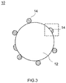
- FIG. 3 is a view schematically showing one example of the positive electrode active material for use in the lithium ion secondary battery 1 in accordance with the present embodiment.
- the positive electrode active material 10 includes a core part 12 and a coating part 14.
- the coating part 14 is formed on at least a partial surface of the core part 12.
- at least some of Ti included in the coating part 14 is incorporated in a solid solution in the surface of the core part 12.
- the core part 12 is a particle including a lithium transition metal composite oxide.
- the crystal structure of the lithium transition metal composite oxide has no particular restriction, and may be a layered structure, a spinel structure, an olivine structure, or the like.
- a lithium transition metal composite oxide including at least one of Ni, Co, and Mn as a transition metal element is preferable.
- the lithium transition metal composite oxide including at least Ni as the transition metal element is in particular preferable.
- the "lithium nickel cobalt manganese type composite oxide” is a term including, other than the oxides including Li, Ni, Co, Mn, or O as the constituent element, even an oxide including one or two or more additive elements other than these.
- an additive element may include transition metal elements and typical metal elements such as Mg, Ca, Al, V, Cr, Y, Zr, Nb, Mo, Hf, Ta, W, Na, Fe, Zn, and Sn.
- the additive elements may be semi-metal elements such as B, C, Si, and P, or non-metal elements such as S, F, Cl, Br, and I.
- lithium nickel type composite oxide, the lithium cobalt type composite oxide, the lithium manganese type composite oxide, the lithium nickel manganese type composite oxide, the lithium nickel cobalt manganese type composite oxide, the lithium nickel cobalt aluminum type composite oxide, the lithium iron nickel manganese type composite oxide, or the like is used as the core part 12.
- lithium nickel cobalt manganese type composite oxide the one having the composition expressed by the following formula (I) is preferable. Li 1 + x Ni y Co z Mn (1-y-z) M ⁇ O 2- ⁇ Q ⁇ (I)
- x, y, z, ⁇ , and ⁇ satisfy 0 ⁇ x ⁇ 0.7, 0.1 ⁇ y ⁇ 0.9, 0.1 ⁇ z ⁇ 0.4, 0 ⁇ ⁇ ⁇ 0.1, and 0 ⁇ ⁇ ⁇ 0.5, respectively.
- M is at least one element selected from the group consisting of Zr, Mo, W, Mg, Ca, Na, Fe, Cr, Zn, Sn, and Al.
- Q is at least one element selected from the group consisting of F, Cl, and Br. From the viewpoint of the energy density and the thermal stability, y and z preferably satisfy 0.3 ⁇ y ⁇ 0.5 and 0.2 ⁇ z ⁇ 0.4, respectively.
- x preferably satisfies 0 ⁇ x ⁇ 0.25, more preferably satisfies 0 ⁇ x ⁇ 0.15, and is further preferably 0.
- ⁇ preferably satisfies 0 ⁇ ⁇ ⁇ 0.05, and more preferably is 0.
- the shape of the core part 12 has no particular restriction, and may be a spherical shape, a sheet shape, a needle shape, an amorphous shape, or the like. Alternatively, the core part 12 may be in a form of a secondary particle including primary particles aggregated therein, or in a hollow form.
- the average particle diameter (median diameter: D50) of the core part 12 is, for example, 0.05 ⁇ m or more and 20 ⁇ m or less, preferably 1 ⁇ m or more and 20 ⁇ m or less, and more preferably 3 ⁇ m or more and 15 ⁇ m or less.
- the average particle diameter (D50) of the core part 12 can be determined by, for example, the laser diffraction scattering method.
- the core part 12 can be manufactured, for example, in the following manner.
- the precursor e.g., metal hydroxide
- the precursor e.g., metal hydroxide
- lithium is introduced into the precursor.
- the core part 12 can be manufactured.
- a coating part 14 is formed on at least a partial surface of the core part 12.
- a coating part 14 includes a titanium-containing compound.
- the coating part 14 includes a composite oxide (which is also referred to as a LiTi composite oxide) including brookite type TiO 2 , and Li and Ti as titanium-containing compounds. Then, at least some of Ti included in the titanium-containing compound is incorporated in a solid solution in the surface of the core part 12 as shown in the square frame of FIG. 3 .
- the coating part 14 may only be present (i.e., be interspersed) on at least a partial surface of the core part 12 as shown in FIG. 3 , and has no particular restriction on the form.
- the coating part 14 may be formed on the entire surface of the core part 12.
- the thickness of the coating part 14 has no particular restriction, the thickness is, for example, 0.1 nm or more and 500 nm or less.
- the thickness of the coating part 14 can be determined by, for example, observing the cross section of the positive electrode active material 10 by Energy Dispersive X-ray Spectroscopy (TEM-EDX) using a transmission electron microscope.
- TEM-EDX Energy Dispersive X-ray Spectroscopy
- At least some of Ti included in the titanium-containing compound is incorporated in a solid solution in the surface of the core part 12. At least some of Ti is incorporated in a solid solution, which can suppress releasing of the coating part 14 from the core part 12. Such a coating part 14 is held by the core part 12. As a result, the collapse of the crystal structure of the core part 12 is suppressed, and the increase in resistance of the secondary battery after repeating cycle charging and discharging is suppressed.
- Ti included in the titanium-containing compound is incorporated in a solid solution in the surface of the core part 12. This can be confirmed, for example, by element mapping by TEM-EDX.
- the coating part 14 includes brookite type TiO 2 as the titanium-containing compound as described above.
- brookite type TiO 2 as the crystal structure of TiO 2 , anatase type (tetragonal), rutile type (tetragonal), brookite type (rhombic), and the like are known.
- the brookite type crystal structure is very unstable as compared with the anatase type and rutile type crystal structures. For example, when the brookite type TiO 2 is heated to 650°C or more, transition to the most stable rutile type TiO 2 is caused. Such brookite type TiO 2 tends to form a complex with Li ions because the crystal structure is unstable.
- the coating part including the brookite type TiO 2 speeds up the extraction and insertion of Li ions from and to the positive electrode active material. As a result, it is possible to reduce the reaction resistance (electric charge transfer resistance) of the positive electrode active material. For this reason, it is also possible to improve the output characteristic of the secondary battery under low temperature environment.
- the coating part 14 includes the brookite type TiO 2 .
- This can be confirmed by a conventionally known method.
- the coating part 14 including the brookite type TiO 2 can be confirmed by performing X-ray absorption fine structure (XAFS) analysis on the coating part 14, and analyzing the Ti peak.
- XAFS X-ray absorption fine structure
- the brookite type TiO 2 has a very unstable crystal structure, and hence has been difficult to use as a coating substance.
- the present inventors conducted a close study thereon, and as a result, found that the coating part 14 including the brookite type TiO 2 can be formed on at least a partial surface of the core part 12 by a mechanochemical treatment.
- the coating part 14 includes a LiTi composite oxide as the titanium-containing compound as described above.
- a LiTi composite oxide such as Li 2 TiO 3 or Li 4 Ti 5 O 12 can be used.
- LiTi composite oxide LiTi composite oxides having different atomic ratios of Li to Ti (Li/Ti) may be used in mixture of two or more thereof.
- the LiTi composite oxide may be synthesized by a conventionally known synthesis method, or may be prepared by purchasing a commercially available product.
- the abundance ratio (A/B) of the Ti abundance (A) as the brookite type TiO 2 and the Ti abundance (B) as the LiTi composite oxide with the Ti abundance included in the coating part 14 taken as 100 is preferably 0.04 or more and 10.1 or less, more preferably 0.1 or more and 4.6 or less, and further preferably 1.4 or more and 4.6 or less.
- the abundance ratio (A/B) of the Ti abundance (A) as the brookite type TiO 2 and the Ti abundance (B) as the LiTi composite oxide can be determined by Ti peak analysis by XAFS.
- Ti peaks of standard samples of Ti included in the titanium-containing compound e.g., brookite type TiO 2 , and Li 2 TiO 3
- the Ti peak of the positive electrode active material 10 (target sample) including the coating part 14 is determined by XAFS analysis.
- the Ti peak of such a standard sample, and the Ti peak of the target sample are subjected to fitting using the analysis software of XAFS (such as Athena or Artemis), thereby to be quantified.
- XAFS such as Athena or Artemis
- the coating part 14 may include other components in such a range so as not to remarkably impair the effects of the present disclosure.
- other components may include TiO 2 (i.e., the anatase type TiO 2 and the rutile type TiO 2 ) other than the brookite type TiO 2 .
- the amount of Ti included in the coating part 14 is preferably 0.1 part or more and 10 parts or less, more preferably 0.3 part or more and 7.5 parts or less, and further preferably 1.5 parts or more and 7.5 parts or less for every 100 parts of the metal elements except for the alkali metal element included in the core part 12 in terms of mol. With such a configuration, the output characteristic under low temperature environment is favorable, and it is possible to suppress the increase in resistance after repeating the charging and discharging cycle.
- the "amount of the metal elements except for alkali metals included in the core part” and the “amount of Ti included in the coating part” can be determined by ICP analysis.
- a positive electrode active material 10 in accordance with the present embodiment can be manufactured, for example, in the following manner. First, a core part 12, and brookite type TiO 2 and a LiTi composite oxide as titanium-containing compounds were charged into a mechanochemical device, and were subjected to a coating treatment. Subsequently, the resulting mixed powder was subjected to a heat treatment, thereby incorporating at least some of Ti included in the titanium-containing compound in a solid solution in the surface of the core part 12. As a result of this, the positive electrode active material 10 can be manufactured.
- the lithium ion secondary battery 1 including the positive electrode active material 10 configured as described up to this point is usable for various uses.
- the lithium ion secondary battery 1 can be preferably used as a high output power source for a motor to be mounted on an automobile (driving power supply).
- the kind of the automobile has no particular restriction.
- a vehicle for example, a plug-in hybrid electric vehicle (PHEV), a hybrid electric vehicle (HEV), or a battery electric vehicle (BEV).
- PHEV plug-in hybrid electric vehicle
- HEV hybrid electric vehicle
- BEV battery electric vehicle
- the lithium ion secondary battery 1 can also be used in a form of an assembled battery including a plurality of batteries electrically connected to one another.
- test examples regarding the present disclosure will be described. However, it is not intended that the present disclosure is limited to such test examples.
- an aqueous solution obtained by dissolving a sulfuric acid salt of a metal other than Li was prepared.
- an aqueous solution including nickel sulfate, cobalt sulfate, and manganese sulfate so that the molar ratios of Ni, Co, and Mn became 1 : 1 : 1 was prepared in a reaction vessel.
- NaOH and aqueous ammonia were added to the aqueous solution in the reaction vessel for neutralization, thereby crystallizing composite hydroxide including other metals than Li to serve as the precursor of the core part.
- the resulting composite hydroxide and lithium carbonate were mixed at prescribed ratios.
- the composite hydroxide and lithium carbonate were mixed so that the molar ratios of (Ni + Co + Mn) : Li became 1 : 1.
- the mixture was burnt at a temperature of 870°C for 15 hours. Such a mixture was cooled to room temperature (25°C ⁇ 5°C), and was subjected to a disaggregation treatment, resulting in a spheroidal particle (core part) including primary particles aggregated therein.
- LiNi 1/3 Co 1/3 Mn 1/3 O 2 , LiCoO 2 , LiMn 2 O 4 , LiNiO 2 , LiNi 0.5 Mn 1.5 O 4 , and LiNi 0.8 Co 0.15 Al 0.05 O 2 were manufactured.
- the resulting core part (LiNi 1/3 Co 1/3 Mn 1/3 O 2 ), and the brookite type TiO 2 ("TIO19PB" manufactured by Kojundo Chemical Lab. Co., Ltd.: purity 4 N) and Li 2 TiO 3 as the titanium-containing compounds were charged into a mechanochemical device, and were subjected to a mechanochemical treatment at a number of revolutions of 6000 rpm for 30 minutes. As a result of this, a coating part including a titanium-containing compound was formed on at least a partial surface of the core part.
- the powder after the mechanochemical treatment was subjected to a heat treatment at a temperature of 500°C for 1 hour. As a result of this, at least some of Ti of the titanium-containing compound was incorporated in a solid solution in the surface of the core part (Example 1).
- LiNi 1/3 Co 1/3 Mn 1/3 O 2 as the core part, and brookite type TiO 2 and Li 2 TiO 3 as titanium-containing compounds were charged into a mechanochemical device, and were subjected to a mechanochemical processing at a number of revolutions of 6000 rpm for 30 minutes.
- the amount of the brookite type TiO 2 and Li 2 TiO 3 at this step was changed, thereby changing the abundance ratio (A/B) of the Ti abundance (A) as titanium dioxide (TiO 2 ) and the Ti abundance (B) as the LiTi composite oxide.
- the powder after the mechanochemical treatment was subjected to a heat treatment at a temperature of 500°C for 1 hour. As a result of this, at least some of Ti of the titanium-containing compound was incorporated in a solid solution in the surface of the core part. In this manner, the active materials of Examples 2 to 5 were obtained.
- LiNi 1/3 Co 1/3 Mn 1/3 O 2 was used as it was (i.e., without being subjected to a mechanochemical treatment) as an active material of Comparative Example 1.
- LiNi 1/3 Co 1/3 Mn 1/3 O 2 as the core part and brookite type TiO 2 and Li 2 TiO 3 as titanium-containing compounds were charged into a mechanochemical device, and were subjected to a mechanochemical treatment at a number of revolutions of 6000 rpm for 30 minutes. This was used as it was (i.e., without being subjected to a heat treatment) as an active material of Comparative Example 2.
- LiNi 1/3 Co 1/3 Mn 1/3 O 2 was prepared as the core part, and the titanium-containing compound was varied, resulting in active materials of Comparative Examples 3 to 6.
- Comparative Example 3 LiNi 1/3 Co 1/3 Mn 1/3 O 2 as the core part, and brookite type TiO 2 as the titanium-containing compound were charged into a mechanochemical device.
- Comparative Example 4 LiNi 1/3 Co 1/3 Mn 1/3 O 2 as the core part and Li 2 TiO 3 as the titanium-containing compound were charged into a mechanochemical device.
- Comparative Example 5 LiNi 1/3 Co 1/3 Mn 1/3 O 2 as the core part, and anatase type TiO 2 and Li 2 TiO 3 as the titanium-containing compounds were charged into a mechanochemical device.
- Comparative Example 6 LiNi 1/3 Co 1/3 Mn 1/3 O 2 as the core part, and rutile type TiO 2 and Li 2 TiO 3 as the titanium-containing compounds were charged into a mechanochemical device.
- the mechanochemical treatment was performed under the conditions of a number of revolutions of 6000 rpm and 30 minutes.
- the powder after the mechanochemical treatment was subjected to a heat treatment at a temperature of 500°C for 1 hour.
- a heat treatment at least some of Ti of the titanium-containing compound was incorporated in a solid solution in the surface of the core part.
- active materials of Comparative Examples 3 to 6 were obtained.
- the abundance ratio (A/B) of the Ti abundance (A) as TiO 2 , and the Ti abundance (B) as the LiTi composite oxide present at the coating part was determined by XAFS analysis. The analysis conditions were set as described below.
- a standard sample of the brookite type TiO 2 and boron nitride were mixed at a molar ratio of 1 : 99 using a dancing mill. Further, a standard sample of Li 2 TiO 3 and boron nitride were mixed at a molar ratio of 1 : 99 using a dancing mill. Such mixtures were pressed under a press pressure of 30 kN, thereby manufacturing each analyzing specimen. Such specimens were analyzed under the conditions of XAFS, thereby determining the Ti peak of the brookite type TiO 2 and the Ti peak of Li 2 TiO 3 . Incidentally, each Ti peak of the anatase type TiO 2 and the rutile type TiO 2 was also determined in the same manner.
- acetylene black (AB) as a conductive material, polyvinylidene fluoride (PVDF) as a binder, and N-methyl pyrrolidone (NMP) as a disperse medium were mixed using a planetary mixer, thereby preparing a positive electrode active material layer forming paste.
- the mass ratios of the active material, AB, and PVDF were set at 90 : 8 : 2, and the solid content concentration was set at 56%.
- a die coater such a paste was applied onto both surfaces of aluminum foil, and was dried, followed by pressing, thereby manufacturing a positive electrode sheet.
- C natural graphite
- SBR styrene butadiene rubber
- CMC carboxyl methyl cellulose
- separator sheets two porous polyolefin sheets each having a three-layered structure of PP/PE/PP, and having a thickness of 24 ⁇ m were prepared.
- the manufactured positive electrode sheet and negative electrode sheet, and the prepared two separator sheets were stacked one on another, and were wound, thereby manufacturing a wound electrode body. Electrode terminals were mounted on the positive electrode sheet and the negative electrode sheet of the manufactured wound electrode body by welding, respectively. This was accommodated in a battery case having a liquid injection port.
- a nonaqueous electrolyte was injected from such a liquid injection port, and the liquid injection port was hermetically sealed by a sealing lid.
- the nonaqueous electrolyte the one obtained by dissolving LiPF 6 as a support salt in a mixed solvent including ethylene carbonate (EC), dimethyl carbonate (DMC), and ethyl methyl carbonate (EMC) at volume ratios of 1 : 1 : 1 in a concentration of 1.0 mol/L was used.
- EC ethylene carbonate
- DMC dimethyl carbonate
- EMC ethyl methyl carbonate
- each evaluating lithium ion secondary battery was subjected to an activating treatment (first charging).
- the activating treatment was performed in the following manner: with the constant current - constant voltage system, constant current charging was performed at a current value of 1/3 C up to 4.2 V, and then, constant voltage charging was performed until the current value became 1/50 C, resulting in a fully charged state. Subsequently, constant current discharging was performed until the voltage became 3.0 V at a current value of 1/3 C.
- Each evaluating lithium ion secondary battery after the activating treatment was adjusted to an open voltage of 3.80 V, and then, was placed under 0°C temperature environment. Discharging was performed at a current value of 1 C for 2 seconds, thereby determining the voltage drop amount ( ⁇ V). Such a voltage drop amount ⁇ V was divided by the discharging current value (1 C), thereby calculating the battery resistance, which was referred to as the initial resistance.
- Comparative Example 1 Comparison between Comparative Example 1, and Examples and other Comparative Examples indicates as follows: provision of the coating part including a titanium-containing compound results in an increase in discharge capacity ratio, and results in a decrease in ratio of the resistance increase rate. Further, comparison between Comparative Examples 2 to 6 and Example 1 indicates as follows: the positive electrode active material having a coating part including a titanium-containing compound on at least the partial surface of the core part, and including brookite type TiO 2 and a LiTi composite oxide as titanium-containing compounds, in which at least some of Ti included in the titanium-containing compound is incorporated in a solid solution in the surface of the core part has a large discharge capacity ratio, and a small ratio of the resistance increase rate. Namely, with the positive electrode active material herein disclosed, it is possible to implement a secondary battery favorable in output characteristic at low temperatures, and suppressed in increase in resistance upon repeating charging and discharging.
- Example 1 when the abundance ratio (A/B) of Ti in the coating part is 0.1 or more and 4.6 or less, the discharge capacity ratio is particularly large, and the ratio of the resistance increase rate is particularly small.
- LiNi 1/3 Co 1/3 Mn 1/3 O 2 as the core part, and brookite type TiO 2 and Li 2 TiO 3 as titanium-containing compounds were charged into a mechanochemical device, and were subjected to a mechanochemical treatment at a number of revolutions of 6000 rpm for 30 minutes.
- a mechanochemical treatment By changing the amount of the brookite type TiO 2 and Li 2 TiO 3 with respect to the amount of the core part, the amount of Ti for every 100 parts of the metal elements except for the alkali metals included in the core part was changed.
- the powder after the mechanochemical treatment was subjected to a heat treatment at a temperature of 500°C for 1 hour. As a result of this, at least some of Ti included in the coating part was incorporated in a soli solution in the surface of the core part. In this manner, the active materials of Examples 6 to 11 were obtained.
- each evaluating lithium ion secondary battery was manufactured in the same manner as described above, and the output characteristic under low temperature environment and the resistance increase rate after cycle charging and discharging were evaluated in the same manner as described above.
- the results shown in Table 2 are the discharge capacity ratio and the ratio of the resistance increase rate of each Example when the result of Comparative Example 1 is assumed to be 1.
- Table 2 also shows the results of Example 1 and Comparative Example 1 together. As shown in Table 2, it is indicated that when the amount of Ti included in the coating part is 0.1 part or more and 10 parts or less, the discharge capacity ratio increases, and the ratio of the resistance increase rate decreases. Further, it is indicated that when the amount of Ti included in the coating part is 0.3 part or more and 7.5 parts or less, the discharge capacity ratio is very large, and the ratio of the resistance increase rate is very small. Still further, it is indicated that when the amount of Ti included in the coating part is 1.5 parts or more and 7.5 parts or less, the discharge capacity ratio is particularly large, and the ratio of the resistance increase rate is particularly small.
- LiCoO 2 , LiMn 2 O 4 , LiNiO 2 , LiNi 0.5 Mn 1.5 O 4 , and LiNi 0.8 Co 0.15 Al 0.05 O 2 were prepared as the core parts.
- Each core part, and the brookite type TiO 2 and Li 2 TiO 3 as titanium-containing compounds were charged into a mechanochemical device, and were subjected to a mechanochemical treatment and a heat treatment under the foregoing conditions, resulting in active materials of Examples 12 to 16.
- LiMn 2 O 4 , LiNiO 2 , LiNi 0.5 Mn 1.5 O 4 , and LiNi 0.8 Co 0.15 Al 0.05 O 2 were used as they were (i.e., without being subjected to a mechanochemical treatment and a heat treatment) as the active materials of Comparative Examples 7 to 11.
- Table 3 also shows the results of Example 1 and Comparative Example 1 together. As shown in Table 3, it is indicated that, in any Example, as compared with Comparative Examples, the output characteristic under low temperature environment of a lithium ion secondary battery is larger, and the resistance increase rate after cycle charging and discharging is smaller. This indicates as follows: regardless of the composition and the crystal structure of the core part, the positive electrode active material in which at least a partial surface of the core part is coated with a coating part including a titanium-containing compound, and at least some of Ti of the titanium-containing compound is incorporated in a solid solution in the surface of the core part is remarkably improved in output characteristic under low temperature environment, and is suppressed in increase in resistance after cycle charging and discharging.
- Examples 1, and 12 to 16 indicate as follows: when the core part is a lithium transition metal composite oxide including at least Ni as a transition metal element, the output characteristic under low temperature environment is particularly improved, and the resistance increase rate after cycle charging and discharging is particularly suppressed.
Abstract
Description
- The present disclosure relates to a positive electrode active material. The present disclosure also relates to a nonaqueous electrolyte secondary battery using the positive electrode active material.
- In recent years, a nonaqueous electrolyte secondary battery such as a lithium ion secondary battery has been preferably used as a portable power supply for a personal computer, a portable terminal, or the like, or a power supply for driving automobiles such as a battery electric vehicle (BEV), a hybrid electric vehicle (HEV), and a plug-in hybrid electric vehicle (PHEV).
- More and more nonaqueous electrolyte secondary batteries are used and have been required to be further enhanced in performances with the spread thereof. For example,
Japanese Patent Application Publication No. 2012-9200 Japanese Patent Application Publication No. 2012-28163 - However, the present inventors conducted a diligent study thereon and found as follows: for a nonaqueous electrolyte secondary battery using a related-art positive electrode or negative electrode active material, there is still room for an improvement in reduction of the reaction resistance under low temperature environment; and the low temperature output characteristic is insufficient. Further, the present inventors found that there is still room for an improvement in effect of suppressing the increase in resistance after repeating a charging and discharging cycle.
- The present disclosure has been made in view of such circumstances. It is a main object of the present disclosure to provide a positive electrode active material for imparting an excellent low temperature output characteristic to a nonaqueous electrolyte secondary battery, and suppressing the increase in resistance after cycle charging and discharging cycle. Further, it is another object thereof to provide a nonaqueous electrolyte secondary battery using such a positive electrode active material.
- In order to achieve the foregoing objects, the positive electrode active material herein disclosed is provided. The positive electrode active material herein disclosed includes: a core part including a lithium transition metal composite oxide; and a coating part including a titanium-containing compound on at least a partial surface of the core part. The titanium-containing compound includes brookite type TiO2 and a LiTi composite oxide including Li and Ti, and at least part of Ti of the titanium-containing compound is incorporated in a solid solution in a surface of the core part.
- As described above, the brookite type TiO2 having the effect of speeding up the insertion/extraction of Li ions, and the LiTi composite oxide including Li and Ti capable of becoming a carrier of Li are coated on the core part. As a result, it is possible to reduce the reaction resistance even under low temperature environment, and to improve the low temperature output characteristic. Further, part of Ti of the titanium-containing compound is incorporated in a solid solution in the surface of the core part. As a result, the coating part becomes more likely to be held on the core part, and the collapse of the crystal structure of the core part can be suppressed, and the increase in resistance of the secondary battery can be suppressed. With such a configuration, it is possible to implement a positive electrode active material for imparting an excellent low temperature output characteristic to the nonaqueous electrolyte secondary battery, and suppressing the increase in resistance after cycle charging and discharging.
- As one preferable aspect of the positive electrode active material herein disclosed, an abundance ratio (A/B) of a Ti abundance (A) as the brookite type TiO2 and a Ti abundance (B) as the LiTi composite oxide is 0.1 or more and 4.6 or less, with a Ti abundance in the coating part calculated based on Ti peak diffraction of XAFS being 100. Further, as another preferable aspect, an amount of Ti included in the coating part is 0.1 part or more and 10 parts or less, relative to 100 parts of a metal element except for an alkali element included in the core part calculated in terms of mol based on ICP analysis.
- With such a configuration, the effects of imparting the nonaqueous electrolyte secondary battery with an excellent low temperature output characteristic, and suppressing the increase in resistance after cycle charging and discharging become particularly high.
- As a still other preferable aspect of the positive electrode active material herein disclosed, the core part includes the lithium transition metal composite oxide including at least Ni as a transition metal element.
- With such a configuration, the effects of imparting the nonaqueous electrolyte secondary battery with an excellent low temperature output characteristic, and suppressing the increase in resistance after cycle charging and discharging become particularly high.
- In order to achieve the other object, a nonaqueous electrolyte secondary battery including a positive electrode, a negative electrode, and a nonaqueous electrolyte is provided. Herein, the positive electrode includes the positive electrode active material.
- With such a configuration, it is possible to provide a nonaqueous electrolyte secondary battery having an excellent low temperature output characteristic, and suppressed in increase in resistance after cycle charging and discharging.
-
-
FIG. 1 is a cross sectional view schematically showing the internal structure of a lithium ion secondary battery in accordance with one embodiment; -
FIG. 2 is view schematically showing the configuration of a wound electrode body of a lithium ion secondary battery in accordance with one embodiment; and -
FIG. 3 is a view schematically showing one example of a positive electrode active material for use in a lithium ion secondary battery in accordance with one embodiment. - Below, referring to the accompanying drawings, preferable embodiments of the present disclosure will be described. It is naturally understood that the embodiments herein described should not be construed as restring the present disclosure. Incidentally, matters necessary for executing the present disclosure, except for matters specifically referred to in the present specification (e.g., a general configuration of a nonaqueous electrolyte secondary battery not characterizing the present disclosure) can be grasped as design matters of those skilled in the art based on the related art in the present field. The present disclosure can be executed based on the contents disclosed in the present specification, and the technical common sense in the present field. Further, a reference sign X in each figure represents the "width direction", and a reference sign Z represents the "height direction". Incidentally, the dimensional relation (such as length, width, or thickness) does not reflect the actual dimensional relation.
- Further, it is assumed that the expression of "A to B (provided that A or B is a given value) showing the range in the present specification means A or more and B or less.
- In the present specification, the term "battery" is a term denoting an electric storage device capable of extracting the electric energy in general, and is a concept including a primary battery and a secondary battery. The term "secondary battery" is a term denoting an electric storage device capable of repeatedly charging and discharging in general, and including a so-called storage battery, and an electric storage element such as an electric double layer capacitor. Further, in the present specification, the term "lithium ion secondary battery" denotes a secondary battery using lithium ions as electric charge carriers, and implementing charging and discharging by the transfer of electric charges accompanying lithium ions between the positive and negative electrodes.
-
FIG. 1 is a cross sectional view schematically showing a lithium ion secondary battery in accordance with one embodiment. As shown inFIG. 1 , a lithium ionsecondary battery 1 is a closed type battery constructed by accommodating awound electrode body 20 in a flat shape and a nonaqueous electrolyte (not shown) in a flat battery case (i.e., an exterior container) 30. Thebattery case 30 is provided with apositive electrode terminal 42 and anegative electrode terminal 44 for external connection, and a thin-walled safety valve 32 set for releasing the internal pressure when the internal pressure of thebattery case 30 increases to a prescribed level, or higher. Thepositive electrode terminal 42 is electrically connected with a positiveelectrode collector sheet 42a. Thenegative electrode terminal 44 is electrically connected with a negativeelectrode collector sheet 44a. As the material for thebattery case 30, for example, a metal material which is lightweight and has good thermal conductivity such as aluminum is used. - The
wound electrode body 20 has a form in which rectangular sheet-shaped positive electrode (which will be hereinafter referred to as a "positive electrode sheet 50") and a rectangular sheet-shaped negative electrode (which will be hereinafter referred to as a "negative electrode sheet 60") are stacked one on another via two long separators (which will be hereinafter referred to as separator sheets 70), and are wound in the longitudinal direction as shown inFIGS. 1 and2 . Thepositive electrode sheet 50 has a configuration in which a positive electrodeactive material layer 54 is formed along the longitudinal direction on one surface or both surfaces of a longpositive electrode collector 52. Thenegative electrode sheet 60 has a configuration in which a negative electrodeactive material layer 64 is formed along the longitudinal direction on one surface or both surfaces of a longnegative electrode collector 62. One edge in the width direction of thepositive electrode collector 52 is provided with a portion at which the positive electrodeactive material layer 54 is not formed along the edge, and thepositive electrode collector 52 is exposed (i.e., a positive electrode collector exposedpart 52a). The other edge in the width direction of thenegative electrode collector 62 is provided with a portion at which the negative electrodeactive material layer 64 is not formed along the edge, and thenegative electrode collector 62 is exposed (i.e., a negative electrode collector exposedpart 62a). The positive electrode collector exposedpart 52a and the negative electrode collector exposedpart 62a are joined with the positiveelectrode collector sheet 42a and the negativeelectrode collector sheet 44a, respectively. - As the
positive electrode collector 52, a conventionally known positive electrode collector for use in a lithium ion secondary battery may be used. As one example thereof, mention may be made of a sheet or foil made of a metal with good electric conductivity (e.g., aluminum, nickel, titanium, or stainless steel). Thepositive electrode collector 52 is preferably, for example, aluminum foil. The dimension of thepositive electrode collector 52 has no particular restriction, and may be appropriately determined according to the battery design. When aluminum foil is used as thepositive electrode collector 52, the dimension is, for example, preferably 5 µm or more and 35 µm or less, and more preferably 7 µm or more and 20 µm or less. - The positive electrode
active material layer 54 includes the positive electrode active material herein disclosed. The positive electrodeactive material layer 54 may include other components than the positive electrode active material, for example, trilithium phosphate, a conductive material, and a binder. As the conductive material, for example, carbon black such as acetylene black (AB), or other carbon materials (e.g., graphite) can be preferably used. As the binder, for example, polyvinylidene fluoride (PVDF) can be used. Further, other materials than the foregoing ones (e.g., various additives) may be included therein unless the effects of the present disclosure are impaired. - Although not particularly restricted, the content of the positive electrode active material in the positive electrode active material layer 54 (i.e., the content of the positive electrode active material based on the total mass of the positive electrode active material layer 54) is preferably 70 mass% or more, more preferably 80 mass% or more and 97 mass% or less, and further preferably 85 mass% or more and 96 mass% or less. The content of trilithium phosphate in the positive electrode
active material layer 54 is preferably, for example, 1 mass% or more and 15 mass% or less, and more preferably 2 mass% or more and 12 mass% or less. The content of the conductive material in the positive electrodeactive material layer 54 is preferably, for example, 1 mass% or more and 15 mass% or less, and more preferably 3 mass% or more and 13 mass% or less. The content of the binder in the positive electrodeactive material layer 54 is, for example, preferably, 1 mass% or more and 15 mass% or less, and more preferably 1.5 mass% or more and 10 mass% or less. - The thickness of the positive electrode
active material layer 54 has no particular restriction, and is for example, preferably, 10 µm or more and 300 µm or less, and more preferably 20 µm or more and 200 µm or less. - As the
negative electrode collector 62, a conventionally known negative electrode collector for use in a lithium ion secondary battery may be used. As one example thereof, mention may be made of a sheet or foil made of a metal with good electrical conductivity (e.g., copper, nickel, titanium, or stainless steel). Thenegative electrode collector 62 is preferably, for example, copper foil. The dimension of thenegative electrode collector 62 has no particular restriction, and may be appropriately determined according to the battery design. When copper foil is used as thenegative electrode collector 62, the dimension is, for example, preferably 5 µm or more and 35 µm or less, and more preferably 7 µm or more 20 µm or less. - The negative electrode
active material layer 64 includes a negative electrode active material. As the negative electrode active material, for example, a carbon material such as graphite, hard carbon, or soft carbon can be preferably used. Graphite may be natural graphite or artificial graphite, and may be amorphous carbon coated graphite in a form in which graphite is coated with an amorphous carbon material. - The average particle diameter (median diameter: D50) of the negative electrode active material has no particular restriction, and is, for example, preferably 0.1 µm or more and 50 µm or less, and more preferably 1 µm or more and 25 µm or less. Incidentally, the average particle diameter (D50) of the negative electrode active material can be determined by, for example, the laser diffraction scattering method.
- As the additive materials other than the negative electrode active material included in the negative electrode
active material layer 64, mention may be made of a binder, a thickener, or the like. As the binder, for example, styrene butadiene rubber (SBR) can be preferably used. As the thickener, for example, carboxymethyl cellulose (CMC), or methyl cellulose(MC) can be preferably used. Further, other materials than the foregoing ones (e.g., various additives) may be included unless the effects of the present disclosure are impaired. - Although not particularly restricted, the content of the negative electrode active material in the negative electrode
active material layer 64 is preferably 90 mass% or more, and more preferably 95 mass% or more and 99 mass% or less. The content of the binder in the negative electrodeactive material layer 64 is, for example, preferably 0.1 mass% or more and 8 mass% or less, and more preferably 0.5 mass% or more and 3 mass% or less. The content of the thickener in the negative electrodeactive material layer 64 is, for example, preferably 0.3 mass% or more and 3 mass% or less, and more preferably 0.5 mass% or more and 2 mass% or less. - The thickness of the negative electrode
active material layer 64 has no particular restriction, and is, for example, preferably 10 µm or more and 300 µm or less, and more preferably 20 µm or more and 200 µm or less. - Examples of the
separator sheet 70 may include a porous sheet (film) including a resin such as polyethylene (PE), polypropylene (PP), polyester, cellulose, or polyamide. Such a porous sheet may be a monolayered structure, or a lamination structure of two or more layers (e.g., a three-layered structure in which PP layers are stacked on both surfaces of a PE layer). Theseparator sheet 70 may be provided with a heat resistant layer (HRL). - For the nonaqueous electrolyte, the same one as that of a conventional lithium ion secondary battery can be used. Typically, the one obtained by allowing a support salt to be included in an organic solvent (nonaqueous solvent) can be used. As the nonaqueous solvents, organic solvents such as carbonates, esters, ethers, nitriles, sulfones, and lactones can be used without particular restriction. Specifically, for example, nonaqueous solvents such as ethylene carbonate (EC), diethyl carbonate (DEC), dimethyl carbonate (DMC), ethyl methyl carbonate (EMC), monofluoroethylene carbonate (MFEC), difluoroethylene carbonate (DFEC), monofluoromethyl difluoromethyl carbonate (F-DMC), and trifluoro dimethyl carbonate (TFDMC) can be preferably used. Such nonaqueous solvents can be used singly alone, or in appropriate combination of two or more thereof.
- As the support salt, for example, a lithium salt such as LiPF6, LiBF4, or LiClO4 can be preferably used. The concentration of the support salt has no particular restriction, and is preferably about 0.7 mol/L or more and 1.3 mol/L or less.
- Incidentally, the nonaqueous electrolyte may include other components than the nonaqueous solvent and the support salt, for example, various additives including a film forming agent such as oxalate complex; a gas generator such as biphenyl (BP) or cyclohexyl benzene (CHB); a dispersant; and a thickener; and the like unless the effects of the present disclosure are remarkably impaired.
- A lithium ion
secondary battery 1 can be manufactured in the same manner as the conventionally known method, except for using the positive electrode active material herein disclosed as the positive electrode active material. - Then, the positive electrode active material for use in the present embodiment will be described.
FIG. 3 is a view schematically showing one example of the positive electrode active material for use in the lithium ionsecondary battery 1 in accordance with the present embodiment. As shown inFIG. 3 , the positive electrodeactive material 10 includes acore part 12 and acoating part 14. Thecoating part 14 is formed on at least a partial surface of thecore part 12. As shown in the square frame ofFIG. 3 , at least some of Ti included in thecoating part 14 is incorporated in a solid solution in the surface of thecore part 12. - The
core part 12 is a particle including a lithium transition metal composite oxide. The crystal structure of the lithium transition metal composite oxide has no particular restriction, and may be a layered structure, a spinel structure, an olivine structure, or the like. As the lithium transition metal composite oxide, a lithium transition metal composite oxide including at least one of Ni, Co, and Mn as a transition metal element is preferable. Specifically, mention may be made of a lithium nickel type composite oxide, a lithium cobalt type composite oxide, a lithium manganese type composite oxide, a lithium nickel manganese type composite oxide, a lithium nickel cobalt manganese type composite oxide, a lithium nickel cobalt aluminum type composite oxide, a lithium iron nickel manganese type composite oxide, and the like. In the present embodiment, the lithium transition metal composite oxide including at least Ni as the transition metal element is in particular preferable. - Incidentally, in the present specification, the "lithium nickel cobalt manganese type composite oxide" is a term including, other than the oxides including Li, Ni, Co, Mn, or O as the constituent element, even an oxide including one or two or more additive elements other than these. Examples of such an additive element may include transition metal elements and typical metal elements such as Mg, Ca, Al, V, Cr, Y, Zr, Nb, Mo, Hf, Ta, W, Na, Fe, Zn, and Sn. Further, the additive elements may be semi-metal elements such as B, C, Si, and P, or non-metal elements such as S, F, Cl, Br, and I. The same also applies to the case where the lithium nickel type composite oxide, the lithium cobalt type composite oxide, the lithium manganese type composite oxide, the lithium nickel manganese type composite oxide, the lithium nickel cobalt manganese type composite oxide, the lithium nickel cobalt aluminum type composite oxide, the lithium iron nickel manganese type composite oxide, or the like is used as the
core part 12. - As the lithium nickel cobalt manganese type composite oxide, the one having the composition expressed by the following formula (I) is preferable.
Li1+xNiyCozMn(1-y-z)MαO2-βQβ (I)
- In the formula (I), x, y, z, α, and β satisfy 0 ≤ x ≤ 0.7, 0.1 < y < 0.9, 0.1 < z < 0.4, 0 ≤ α ≤ 0.1, and 0 ≤ β ≤ 0.5, respectively. M is at least one element selected from the group consisting of Zr, Mo, W, Mg, Ca, Na, Fe, Cr, Zn, Sn, and Al. Q is at least one element selected from the group consisting of F, Cl, and Br. From the viewpoint of the energy density and the thermal stability, y and z preferably satisfy 0.3 ≤ y ≤ 0.5 and 0.2 ≤ z ≤ 0.4, respectively. x preferably satisfies 0 ≤ x ≤ 0.25, more preferably satisfies 0 ≤ x ≤ 0.15, and is further preferably 0. α preferably satisfies 0 ≤ α ≤ 0.05, and more preferably is 0. β preferably satisfies 0 ≤ β ≤ 0.1, and more preferably is 0.
- The shape of the
core part 12 has no particular restriction, and may be a spherical shape, a sheet shape, a needle shape, an amorphous shape, or the like. Alternatively, thecore part 12 may be in a form of a secondary particle including primary particles aggregated therein, or in a hollow form. The average particle diameter (median diameter: D50) of thecore part 12 is, for example, 0.05 µm or more and 20 µm or less, preferably 1 µm or more and 20 µm or less, and more preferably 3 µm or more and 15 µm or less. Incidentally, the average particle diameter (D50) of thecore part 12 can be determined by, for example, the laser diffraction scattering method. - Incidentally, the
core part 12 can be manufactured, for example, in the following manner. The precursor (e.g., metal hydroxide) of a lithium transition metal composite oxide is manufactured by the crystallization method, or the like, and lithium is introduced into the precursor. As a result, thecore part 12 can be manufactured. - A
coating part 14 is formed on at least a partial surface of thecore part 12. Such acoating part 14 includes a titanium-containing compound. Thecoating part 14 includes a composite oxide (which is also referred to as a LiTi composite oxide) including brookite type TiO2, and Li and Ti as titanium-containing compounds. Then, at least some of Ti included in the titanium-containing compound is incorporated in a solid solution in the surface of thecore part 12 as shown in the square frame ofFIG. 3 . - The
coating part 14 may only be present (i.e., be interspersed) on at least a partial surface of thecore part 12 as shown inFIG. 3 , and has no particular restriction on the form. For example, thecoating part 14 may be formed on the entire surface of thecore part 12. Although the thickness of thecoating part 14 has no particular restriction, the thickness is, for example, 0.1 nm or more and 500 nm or less. The thickness of thecoating part 14 can be determined by, for example, observing the cross section of the positive electrodeactive material 10 by Energy Dispersive X-ray Spectroscopy (TEM-EDX) using a transmission electron microscope. - In the present embodiment, at least some of Ti included in the titanium-containing compound is incorporated in a solid solution in the surface of the
core part 12. At least some of Ti is incorporated in a solid solution, which can suppress releasing of thecoating part 14 from thecore part 12. Such acoating part 14 is held by thecore part 12. As a result, the collapse of the crystal structure of thecore part 12 is suppressed, and the increase in resistance of the secondary battery after repeating cycle charging and discharging is suppressed. - Incidentally, at least some of Ti included in the titanium-containing compound is incorporated in a solid solution in the surface of the
core part 12. This can be confirmed, for example, by element mapping by TEM-EDX. - The
coating part 14 includes brookite type TiO2 as the titanium-containing compound as described above. Generally, as the crystal structure of TiO2, anatase type (tetragonal), rutile type (tetragonal), brookite type (rhombic), and the like are known. The brookite type crystal structure is very unstable as compared with the anatase type and rutile type crystal structures. For example, when the brookite type TiO2 is heated to 650°C or more, transition to the most stable rutile type TiO2 is caused. Such brookite type TiO2 tends to form a complex with Li ions because the crystal structure is unstable. For this reason, the coating part including the brookite type TiO2 speeds up the extraction and insertion of Li ions from and to the positive electrode active material. As a result, it is possible to reduce the reaction resistance (electric charge transfer resistance) of the positive electrode active material. For this reason, it is also possible to improve the output characteristic of the secondary battery under low temperature environment. - Incidentally, the
coating part 14 includes the brookite type TiO2. This can be confirmed by a conventionally known method. For example, thecoating part 14 including the brookite type TiO2 can be confirmed by performing X-ray absorption fine structure (XAFS) analysis on thecoating part 14, and analyzing the Ti peak. - The brookite type TiO2 has a very unstable crystal structure, and hence has been difficult to use as a coating substance. However, the present inventors conducted a close study thereon, and as a result, found that the
coating part 14 including the brookite type TiO2 can be formed on at least a partial surface of thecore part 12 by a mechanochemical treatment. - The
coating part 14 includes a LiTi composite oxide as the titanium-containing compound as described above. As the LiTi composite oxide, for example, a LiTi composite oxide such as Li2TiO3 or Li4Ti5O12 can be used. As the LiTi composite oxide, LiTi composite oxides having different atomic ratios of Li to Ti (Li/Ti) may be used in mixture of two or more thereof. - Incidentally, the LiTi composite oxide may be synthesized by a conventionally known synthesis method, or may be prepared by purchasing a commercially available product.
- The abundance ratio (A/B) of the Ti abundance (A) as the brookite type TiO2 and the Ti abundance (B) as the LiTi composite oxide with the Ti abundance included in the
coating part 14 taken as 100 is preferably 0.04 or more and 10.1 or less, more preferably 0.1 or more and 4.6 or less, and further preferably 1.4 or more and 4.6 or less. - Incidentally, the abundance ratio (A/B) of the Ti abundance (A) as the brookite type TiO2 and the Ti abundance (B) as the LiTi composite oxide can be determined by Ti peak analysis by XAFS. Although specific measurement device and measurement conditions will be described in examples described later, for example, the Ti peaks of standard samples of Ti included in the titanium-containing compound (e.g., brookite type TiO2, and Li2TiO3) are respectively determined by XAFS analysis. Then, the Ti peak of the positive electrode active material 10 (target sample) including the
coating part 14 is determined by XAFS analysis. The Ti peak of such a standard sample, and the Ti peak of the target sample are subjected to fitting using the analysis software of XAFS (such as Athena or Artemis), thereby to be quantified. As a result of this, the abundance ratio (A/B) of the Ti abundance (A) as the brookite type TiO2 and the Ti abundance (B) as the LiTi composite oxide can be determined. - Incidentally, the
coating part 14 may include other components in such a range so as not to remarkably impair the effects of the present disclosure. Examples of other components may include TiO2 (i.e., the anatase type TiO2 and the rutile type TiO2) other than the brookite type TiO2. - The amount of Ti included in the
coating part 14 is preferably 0.1 part or more and 10 parts or less, more preferably 0.3 part or more and 7.5 parts or less, and further preferably 1.5 parts or more and 7.5 parts or less for every 100 parts of the metal elements except for the alkali metal element included in thecore part 12 in terms of mol. With such a configuration, the output characteristic under low temperature environment is favorable, and it is possible to suppress the increase in resistance after repeating the charging and discharging cycle. - Incidentally, the "amount of the metal elements except for alkali metals included in the core part" and the "amount of Ti included in the coating part" can be determined by ICP analysis.
- A positive electrode
active material 10 in accordance with the present embodiment can be manufactured, for example, in the following manner. First, acore part 12, and brookite type TiO2 and a LiTi composite oxide as titanium-containing compounds were charged into a mechanochemical device, and were subjected to a coating treatment. Subsequently, the resulting mixed powder was subjected to a heat treatment, thereby incorporating at least some of Ti included in the titanium-containing compound in a solid solution in the surface of thecore part 12. As a result of this, the positive electrodeactive material 10 can be manufactured. - The lithium ion
secondary battery 1 including the positive electrodeactive material 10 configured as described up to this point is usable for various uses. For example, the lithium ionsecondary battery 1 can be preferably used as a high output power source for a motor to be mounted on an automobile (driving power supply). The kind of the automobile has no particular restriction. Typically, mention may be made of a vehicle, for example, a plug-in hybrid electric vehicle (PHEV), a hybrid electric vehicle (HEV), or a battery electric vehicle (BEV). The lithium ionsecondary battery 1 can also be used in a form of an assembled battery including a plurality of batteries electrically connected to one another. - Below, test examples regarding the present disclosure will be described. However, it is not intended that the present disclosure is limited to such test examples.
- First, an aqueous solution obtained by dissolving a sulfuric acid salt of a metal other than Li was prepared. For example, when a LiNi1/3Co1/3Ni1/3O2 particle having a layered structure was manufactured as the core part, an aqueous solution including nickel sulfate, cobalt sulfate, and manganese sulfate so that the molar ratios of Ni, Co, and Mn became 1 : 1 : 1 was prepared in a reaction vessel. NaOH and aqueous ammonia were added to the aqueous solution in the reaction vessel for neutralization, thereby crystallizing composite hydroxide including other metals than Li to serve as the precursor of the core part. The resulting composite hydroxide and lithium carbonate were mixed at prescribed ratios. For example, when a LiNi1/3Co1/3Mn1/3O2 particle having a layered structure was manufactured as the core part, the composite hydroxide and lithium carbonate were mixed so that the molar ratios of (Ni + Co + Mn) : Li became 1 : 1. The mixture was burnt at a temperature of 870°C for 15 hours. Such a mixture was cooled to room temperature (25°C ± 5°C), and was subjected to a disaggregation treatment, resulting in a spheroidal particle (core part) including primary particles aggregated therein.
- In this manner, as the core parts, LiNi1/3Co1/3Mn1/3O2, LiCoO2, LiMn2O4, LiNiO2, LiNi0.5Mn1.5O4, and LiNi0.8Co0.15Al0.05O2 were manufactured.
- The resulting core part (LiNi1/3Co1/3Mn1/3O2), and the brookite type TiO2 ("TIO19PB" manufactured by Kojundo Chemical Lab. Co., Ltd.: purity 4 N) and Li2TiO3 as the titanium-containing compounds were charged into a mechanochemical device, and were subjected to a mechanochemical treatment at a number of revolutions of 6000 rpm for 30 minutes. As a result of this, a coating part including a titanium-containing compound was formed on at least a partial surface of the core part. The powder after the mechanochemical treatment was subjected to a heat treatment at a temperature of 500°C for 1 hour. As a result of this, at least some of Ti of the titanium-containing compound was incorporated in a solid solution in the surface of the core part (Example 1).
- LiNi1/3Co1/3Mn1/3O2 as the core part, and brookite type TiO2 and Li2TiO3 as titanium-containing compounds were charged into a mechanochemical device, and were subjected to a mechanochemical processing at a number of revolutions of 6000 rpm for 30 minutes. The amount of the brookite type TiO2 and Li2TiO3 at this step was changed, thereby changing the abundance ratio (A/B) of the Ti abundance (A) as titanium dioxide (TiO2) and the Ti abundance (B) as the LiTi composite oxide. The powder after the mechanochemical treatment was subjected to a heat treatment at a temperature of 500°C for 1 hour. As a result of this, at least some of Ti of the titanium-containing compound was incorporated in a solid solution in the surface of the core part. In this manner, the active materials of Examples 2 to 5 were obtained.
- LiNi1/3Co1/3Mn1/3O2 was used as it was (i.e., without being subjected to a mechanochemical treatment) as an active material of Comparative Example 1.
- LiNi1/3Co1/3Mn1/3O2 as the core part and brookite type TiO2 and Li2TiO3 as titanium-containing compounds were charged into a mechanochemical device, and were subjected to a mechanochemical treatment at a number of revolutions of 6000 rpm for 30 minutes. This was used as it was (i.e., without being subjected to a heat treatment) as an active material of Comparative Example 2.
- LiNi1/3Co1/3Mn1/3O2 was prepared as the core part, and the titanium-containing compound was varied, resulting in active materials of Comparative Examples 3 to 6.
- In Comparative Example 3, LiNi1/3Co1/3Mn1/3O2 as the core part, and brookite type TiO2 as the titanium-containing compound were charged into a mechanochemical device.
- In Comparative Example 4, LiNi1/3Co1/3Mn1/3O2 as the core part and Li2TiO3 as the titanium-containing compound were charged into a mechanochemical device.
- In Comparative Example 5, LiNi1/3Co1/3Mn1/3O2 as the core part, and anatase type TiO2 and Li2TiO3 as the titanium-containing compounds were charged into a mechanochemical device.
- In Comparative Example 6, LiNi1/3Co1/3Mn1/3O2 as the core part, and rutile type TiO2 and Li2TiO3 as the titanium-containing compounds were charged into a mechanochemical device.
- The mechanochemical treatment was performed under the conditions of a number of revolutions of 6000 rpm and 30 minutes. The powder after the mechanochemical treatment was subjected to a heat treatment at a temperature of 500°C for 1 hour. As a result of this, at least some of Ti of the titanium-containing compound was incorporated in a solid solution in the surface of the core part. In this manner, active materials of Comparative Examples 3 to 6 were obtained.
- Using TEM-EDX (TEM device: JFE-ARM300F, EDX device: JED-2300T manufactured by JEOL), element mapping was performed, and the positive electrode active material of each Example was observed. As a result, for Examples 1 to 5, and Comparative Examples 3 to 6, in each of which a heat treatment was performed, it could be observed that at least some of Ti of the titanium-containing compound was incorporated in a solid solution. The results are shown in Table 1.
- The abundance ratio (A/B) of the Ti abundance (A) as TiO2, and the Ti abundance (B) as the LiTi composite oxide present at the coating part was determined by XAFS analysis. The analysis conditions were set as described below.
- Analyzer: Aichi Synchrotron Radiation Center BL5S1
- Measurement method: transmission method (standard sample) and the fluorescence method (Example and Comparative Example).
- Monochromator: double crystal spectrometer
- Analyzing crystal: Si (111)
- Measurement absorption edge: Ti-K absorption edge
- Measurement energy region: 4800 eV to 6000 eV
- Analysis software: Athena (Demeter ver. 0.9.26)
- A standard sample of the brookite type TiO2 and boron nitride were mixed at a molar ratio of 1 : 99 using a dancing mill. Further, a standard sample of Li2TiO3 and boron nitride were mixed at a molar ratio of 1 : 99 using a dancing mill. Such mixtures were pressed under a press pressure of 30 kN, thereby manufacturing each analyzing specimen. Such specimens were analyzed under the conditions of XAFS, thereby determining the Ti peak of the brookite type TiO2 and the Ti peak of Li2TiO3. Incidentally, each Ti peak of the anatase type TiO2 and the rutile type TiO2 was also determined in the same manner.
- Then, the active materials of Examples 1 to 5 and Comparative Examples 1 to 6 were pressed under a press pressure of 30 kN, thereby manufacturing respective analyzing specimens. These were measured under the conditions of XAFS, and their respective Ti peaks were determined. The Ti peak of TiO2 and the Ti peak of Li2TiO3 determined by the measurement of the standard samples, and the Ti peaks of respective examples (around 5000 eV) were subjected to fitting using analysis software Athena for quantification. As a result of this, the Ti abundance (A) as TiO2 and the Ti abundance (B) as LiTi composite oxide were determined, thereby calculating the abundance ratio (A/B) (which will be hereinafter referred to as the abundance ratio (A/B) of Ti in the coating part). The results are shown in Table 1.
- Each active material of respective Examples and respective Comparative Examples manufactured, acetylene black (AB) as a conductive material, polyvinylidene fluoride (PVDF) as a binder, and N-methyl pyrrolidone (NMP) as a disperse medium were mixed using a planetary mixer, thereby preparing a positive electrode active material layer forming paste. At this step, the mass ratios of the active material, AB, and PVDF were set at 90 : 8 : 2, and the solid content concentration was set at 56%. Using a die coater, such a paste was applied onto both surfaces of aluminum foil, and was dried, followed by pressing, thereby manufacturing a positive electrode sheet.
- Further, natural graphite (C) as a negative electrode active material, styrene butadiene rubber (SBR) as a binder, and carboxyl methyl cellulose (CMC) as a thickener were mixed at mass ratios of C : SBR : CMC = 98 : 1 : 1 in ion exchanged water, thereby preparing a negative electrode active material layer forming paste. Using a die coater, such a paste was applied onto both surfaces of copper foil, and was dried, followed by pressing, thereby manufacturing a negative electrode sheet.
- As the separator sheets, two porous polyolefin sheets each having a three-layered structure of PP/PE/PP, and having a thickness of 24 µm were prepared.
- The manufactured positive electrode sheet and negative electrode sheet, and the prepared two separator sheets were stacked one on another, and were wound, thereby manufacturing a wound electrode body. Electrode terminals were mounted on the positive electrode sheet and the negative electrode sheet of the manufactured wound electrode body by welding, respectively. This was accommodated in a battery case having a liquid injection port.
- A nonaqueous electrolyte was injected from such a liquid injection port, and the liquid injection port was hermetically sealed by a sealing lid. Incidentally, as the nonaqueous electrolyte, the one obtained by dissolving LiPF6 as a support salt in a mixed solvent including ethylene carbonate (EC), dimethyl carbonate (DMC), and ethyl methyl carbonate (EMC) at volume ratios of 1 : 1 : 1 in a concentration of 1.0 mol/L was used. In the manner described up to this point, an evaluating lithium ion secondary battery was obtained.
- Under 25°C environment, each evaluating lithium ion secondary battery was subjected to an activating treatment (first charging). The activating treatment was performed in the following manner: with the constant current - constant voltage system, constant current charging was performed at a current value of 1/3 C up to 4.2 V, and then, constant voltage charging was performed until the current value became 1/50 C, resulting in a fully charged state. Subsequently, constant current discharging was performed until the voltage became 3.0 V at a current value of 1/3 C.
- Each evaluating lithium ion secondary battery after the activating treatment was adjusted to an open voltage of 4.0 V, and then was placed under -10°C temperature environment. Constant current discharging was performed at a discharging rate of 1 C to 3.0 V, thereby measuring the discharge capacity. Further, under the same conditions, adjustment was performed to an open voltage of 4.0 V, and then, constant current discharging was performed at a discharging rate of 10 C to 3.0 V, thereby measuring the discharge capacity. The discharge capacity of 10 C was divided by the discharge capacity of 1 C, thereby calculating the discharge capacity under low temperature environment. The discharge capacity ratios of other Comparative Examples and Examples when the discharge capacity of Comparative Example 1 was assumed to be 1 were determined. Incidentally, the larger such a discharge capacity ratio is, the higher the output characteristic under low temperature environment can be evaluated. The results are shown in Table 1.
- Each evaluating lithium ion secondary battery after the activating treatment was adjusted to an open voltage of 3.80 V, and then, was placed under 0°C temperature environment. Discharging was performed at a current value of 1 C for 2 seconds, thereby determining the voltage drop amount (Δ V). Such a voltage drop amount Δ V was divided by the discharging current value (1 C), thereby calculating the battery resistance, which was referred to as the initial resistance.
- Each evaluating lithium ion secondary battery for which the initial resistance was measured was placed under 0°C environment. Thus, the charging and discharging cycle including constant current charging at 30 C to 4.3 V, and constant current discharging at 30 C to 3.1 V as one cycle was repeated for 500 cycles. The battery resistance at the 500th cycle was measured in the same manner as described above. The resistance increase rate was determined by the formula: (battery resistance at 500th charging and discharging cycle - initial resistance)/initial resistance. The ratios of the resistance increase rates of other Comparative Examples and Examples when the resistance increase rate of Comparative Example 1 was assumed to be 1 were determined. Incidentally, it can be evaluated as follows: the smaller such a ratio of the resistance increase rate is, the more the increase in resistance upon repeating charging and discharging is suppressed. The results are shown in Table 1.
- [Table 1]
Table 1 Incorporatio n in solid solution of Ti Crystal structure of TiO2 Ti abundan ce as TiO2 (A) Ti abundance as LiTi composite oxide (B) Abund ance ratio (A/B) Discharg e capacity ratio Ratio of resistance increase rate Comparative Example 1 None - 0 0 - 1.00 1.00 Comparative Example 2 None Brookite type 59 41 1.4 1.25 0.95 Comparative Example 3 Observed Brookite type 100 0 - 1.08 0.83 Comparative Example 4 Observed - 0 100 - 1.09 0.91 Comparative Example 5 Observed Anatase type 62 38 1.6 1.11 0.84 Comparative Example 6 Observed Rutile type 63 37 1.7 1.18 0.82 Example 1 Observed Brookite type 59 41 1.4 1.54 0.67 Example 2 Observed Brookite type 4 96 0.04 1.29 0.76 Example 3 Observed Brookite type 10 90 0.1 1.50 0.68 Example 4 Observed Brookite type 82 18 4.6 1.45 0.70 Example 5 Observed Brookite type 91 9 10.1 1.27 0.80 - Comparison between Comparative Example 1, and Examples and other Comparative Examples indicates as follows: provision of the coating part including a titanium-containing compound results in an increase in discharge capacity ratio, and results in a decrease in ratio of the resistance increase rate. Further, comparison between Comparative Examples 2 to 6 and Example 1 indicates as follows: the positive electrode active material having a coating part including a titanium-containing compound on at least the partial surface of the core part, and including brookite type TiO2 and a LiTi composite oxide as titanium-containing compounds, in which at least some of Ti included in the titanium-containing compound is incorporated in a solid solution in the surface of the core part has a large discharge capacity ratio, and a small ratio of the resistance increase rate. Namely, with the positive electrode active material herein disclosed, it is possible to implement a secondary battery favorable in output characteristic at low temperatures, and suppressed in increase in resistance upon repeating charging and discharging.
- Further, comparison among Examples 1 to 5 indicates as follows: when the abundance ratio (A/B) of Ti in the coating part is 0.1 or more and 4.6 or less, the discharge capacity ratio is particularly large, and the ratio of the resistance increase rate is particularly small.
- LiNi1/3Co1/3Mn1/3O2 as the core part, and brookite type TiO2 and Li2TiO3 as titanium-containing compounds were charged into a mechanochemical device, and were subjected to a mechanochemical treatment at a number of revolutions of 6000 rpm for 30 minutes. By changing the amount of the brookite type TiO2 and Li2TiO3 with respect to the amount of the core part, the amount of Ti for every 100 parts of the metal elements except for the alkali metals included in the core part was changed. The powder after the mechanochemical treatment was subjected to a heat treatment at a temperature of 500°C for 1 hour. As a result of this, at least some of Ti included in the coating part was incorporated in a soli solution in the surface of the core part. In this manner, the active materials of Examples 6 to 11 were obtained.
- By performing element mapping using TEM-EDX as described above, it was confirmed that at least some of Ti of the titanium-containing compound was incorporated in a solid solution. Further, the abundance ratio (A/B) of Ti in the coating part was calculated by the foregoing procedure based on the Ti peak analysis by XAFS.
- By quantitative analysis using ICP emission analyzer (ion chromatograph ISC-5000 manufactured by Nippon Dionex K.K.), the "amount of metal elements except for the alkali metals included in the core part" and the "amount of Ti included in the coating part" were calculated in terms of mol. As a result of this, the amount of Ti included in the coating part for every 100 parts of the metal elements except for the alkali metals included in the core part (which will be hereinafter referred to as the amount of Ti included in the coating part) was calculated. The results are shown in Table 2.
- Using the active materials, each evaluating lithium ion secondary battery was manufactured in the same manner as described above, and the output characteristic under low temperature environment and the resistance increase rate after cycle charging and discharging were evaluated in the same manner as described above. Incidentally, the results shown in Table 2 are the discharge capacity ratio and the ratio of the resistance increase rate of each Example when the result of Comparative Example 1 is assumed to be 1.
- [Table 2]
Table 2 Incorporati on in solid solution of Ti Ti abundanc e as TiO2 (A) Ti abundance as LiTi composite oxide (B) Abunda nce ratio (A/B) Amoun t of Ti (part(s) ) Discharg e capacity ratio Ratio of resistanc e increase rate Comparative Example 1 None 0 0 - - 1.00 1.00 Example 1 Observed 59 41 1.4 2.5 1.54 0.67 Example 6 Observed 60 40 1.5 0.1 1.36 0.81 Example 7 Observed 59 41 1.4 0.3 1.49 0.72 Example 8 Observed 58 42 1.4 1.5 1.63 0.72 Example 9 Observed 59 41 1.4 5 1.59 0.65 Example 10 Observed 59 41 1.4 7.5 1.45 0.67 Example 11 Observed 58 42 1.4 10 1.28 0.70 ∗ The amount of Ti (part(s)) is the amount of Ti (part(s)) included in the core part for every 100 parts of the metal elements except for the alkali metal elements included in the core part in terms of mol. - Table 2 also shows the results of Example 1 and Comparative Example 1 together. As shown in Table 2, it is indicated that when the amount of Ti included in the coating part is 0.1 part or more and 10 parts or less, the discharge capacity ratio increases, and the ratio of the resistance increase rate decreases. Further, it is indicated that when the amount of Ti included in the coating part is 0.3 part or more and 7.5 parts or less, the discharge capacity ratio is very large, and the ratio of the resistance increase rate is very small. Still further, it is indicated that when the amount of Ti included in the coating part is 1.5 parts or more and 7.5 parts or less, the discharge capacity ratio is particularly large, and the ratio of the resistance increase rate is particularly small.
- LiCoO2, LiMn2O4, LiNiO2, LiNi0.5Mn1.5O4, and LiNi0.8Co0.15Al0.05O2 were prepared as the core parts. Each core part, and the brookite type TiO2 and Li2TiO3 as titanium-containing compounds were charged into a mechanochemical device, and were subjected to a mechanochemical treatment and a heat treatment under the foregoing conditions, resulting in active materials of Examples 12 to 16. On the other hand, LiMn2O4, LiNiO2, LiNi0.5Mn1.5O4, and LiNi0.8Co0.15Al0.05O2 were used as they were (i.e., without being subjected to a mechanochemical treatment and a heat treatment) as the active materials of Comparative Examples 7 to 11.
- For Examples 1, and 12 to 16, the abundance ratios (A/B) of Ti in the coating part and the amounts of Ti included in the coating part were adjusted so as to be roughly equal.
- Using each active material of Examples 12 to 16 and Comparative Examples 7 to 11, an evaluating lithium ion secondary battery was manufactured in the same manner as described above, and the output characteristic under low temperature environment and the resistance increase rate after cycle charging and discharging were evaluated in the same manner as described above. Incidentally, the results shown in Table 3 are the discharge capacity ratios and the ratios of the resistance increase rate of other Comparative Examples and Examples when the result of Comparative Example 1 is assumed to be 1.
- [Table 3]
Table 3 Base material active material Incorpora tion in solid solution of Ti Ti abunda nce as TiO2 (A) Ti abundanc e as LiTi composit e oxide (B) Abund ance ratio (A/B) Amo unt of Ti (part( s)) Disch arge capaci ty ratio Ratio of resista nce increas e rate Comparativ e Example 1 LiNi0.33Co0.33 Mn0.33O2 None 0 0 - - 1.00 1.00 Example 1 LiNi0.33Co0.33 Mn0.33O2 Observed 59 41 1.4 2.5 1.54 0.67 Comparativ e Example 7 LiCoO2 None 0 0 - - 1.00 1.00 Example 12 LiCoO2 Observed 60 40 1.5 2.5 1.45 0.76 Comparativ e Example 8 LiMn2O4 None 0 0 - - 1.00 1.00 Example 13 LiMn2O4 Observed 60 40 1.5 2.5 1.39 0.74 Comparativ e Example 9 LiNiO2 None 0 0 - - 1.00 1.00 Example 14 LiNiO2 Observed 58 42 1.4 2.5 1.54 0.69 Comparativ e Example 10 LiNi0.5Mn1.5O4 None 0 0 - - 1.00 1.00 Example 15 LiNi0.5Mn1.5O4 Observed 59 41 1.4 2.5 1.47 0.68 Comparativ e Example 11 LiNi0.8Co0.15Al 0.05O2 None 0 0 - - 1.00 1.00 Example 16 LiNi0.8Co0.15Al 0.05O2 Observed 59 41 1.4 2.5 1.49 0.68 ∗ The amount of Ti (part(s)) is the amount of Ti (part(s)) included in the core part for every 100 parts of the metal elements except for the alkali metal elements included in the core part in terms of mol. - Table 3 also shows the results of Example 1 and Comparative Example 1 together. As shown in Table 3, it is indicated that, in any Example, as compared with Comparative Examples, the output characteristic under low temperature environment of a lithium ion secondary battery is larger, and the resistance increase rate after cycle charging and discharging is smaller. This indicates as follows: regardless of the composition and the crystal structure of the core part, the positive electrode active material in which at least a partial surface of the core part is coated with a coating part including a titanium-containing compound, and at least some of Ti of the titanium-containing compound is incorporated in a solid solution in the surface of the core part is remarkably improved in output characteristic under low temperature environment, and is suppressed in increase in resistance after cycle charging and discharging. Further, comparison among Examples 1, and 12 to 16 indicates as follows: when the core part is a lithium transition metal composite oxide including at least Ni as a transition metal element, the output characteristic under low temperature environment is particularly improved, and the resistance increase rate after cycle charging and discharging is particularly suppressed.
- Up to this point, specific examples of the present disclosure were described in details. However, these are merely illustrative, and should not be construed as limiting the scope of the appended claims. The technology described in the appended claims includes various modifications and changes of the specific examples exemplified up to this point.
Claims (5)
- A positive electrode active material (10) for use in a nonaqueous electrolyte secondary battery (1),
the positive electrode active material (10), comprising:a core part (12) including a lithium transition metal composite oxide; anda coating part (14) including a titanium-containing compound on at least a partial surface of the core part (12), whereinthe titanium-containing compound includes brookite type TiO2 and a LiTi composite oxide including Li and Ti, andat least part of Ti of the titanium-containing compound is incorporated in a solid solution in a surface of the core part (12). - The positive electrode active material (10) according to claim 1,
wherein an abundance ratio (A/B) of a Ti abundance (A) as the brookite type TiO2 and a Ti abundance (B) as the LiTi composite oxide is 0.1 or more and 4.6 or less, with a Ti abundance in the coating part (14) calculated based on Ti peak analysis of XAFS being 100. - The positive electrode active material (10) according to claim 1 or 2,
wherein an amount of Ti included in the coating part (14) is 0.1 part or more and 10 parts or less, relative to 100 parts of a metal element except for an alkali metal element included in the core part (12) calculated in terms of mol based on ICP analysis. - The positive electrode active material (10) according to any one of claims 1 to 3, wherein the core part (12) includes the lithium transition metal composite oxide including at least Ni as a transition metal element.
- A nonaqueous electrolyte secondary battery (1) comprising a positive electrode (50), a negative electrode (60), and a nonaqueous electrolyte, wherein
the positive electrode (50) includes the positive electrode active material (10) according to any one of claims 1 to 4.
Applications Claiming Priority (1)
| Application Number | Priority Date | Filing Date | Title |
|---|---|---|---|
| JP2021006797A JP7208274B2 (en) | 2021-01-20 | 2021-01-20 | Positive electrode active material and non-aqueous electrolyte secondary battery using the positive electrode active material |
Publications (2)
| Publication Number | Publication Date |
|---|---|
| EP4032858A1 true EP4032858A1 (en) | 2022-07-27 |
| EP4032858B1 EP4032858B1 (en) | 2023-08-30 |
Family
ID=78820889
Family Applications (1)
| Application Number | Title | Priority Date | Filing Date |
|---|---|---|---|
| EP21211684.2A Active EP4032858B1 (en) | 2021-01-20 | 2021-12-01 | Positive electrode active material and nonaqueous electrolyte secondary battery using the positive electrode active material |
Country Status (4)
| Country | Link |
|---|---|
| US (1) | US20220231277A1 (en) |
| EP (1) | EP4032858B1 (en) |
| JP (1) | JP7208274B2 (en) |
| CN (1) | CN114824244B (en) |
Cited By (1)
| Publication number | Priority date | Publication date | Assignee | Title |
|---|---|---|---|---|
| WO2024079307A1 (en) * | 2022-10-14 | 2024-04-18 | Umicore | Positive electrode active material and method for manufacturing a positive electrode active material |
Citations (6)
| Publication number | Priority date | Publication date | Assignee | Title |
|---|---|---|---|---|
| JP2002151078A (en) * | 2000-11-14 | 2002-05-24 | Toda Kogyo Corp | Positive electrode active material for non-aqueous electrolyte secondary battery and its manufacturing process |
| JP2012009200A (en) | 2010-06-23 | 2012-01-12 | Sony Corp | Manufacturing method of conductive material, conductive material, and battery |
| JP2012028163A (en) | 2010-07-23 | 2012-02-09 | Sumitomo Metal Mining Co Ltd | Positive electrode active material for nonaqueous electrolyte secondary battery, method of manufacturing the same, and nonaqueous electrolyte secondary battery |
| US20120156565A1 (en) * | 2010-12-20 | 2012-06-21 | Samsung Sdi Co., Ltd. | Positive electrode active material, method of manufacturing the positive electrode active material, and lithium battery employing the positive electrode active material |
| US20170222223A1 (en) * | 2016-01-28 | 2017-08-03 | Gs Energy Corp. | Cathode active material having excellent electrochemical properties and lithium secondary battery comprising the same |
| CN110212187A (en) * | 2019-06-13 | 2019-09-06 | 燕山大学 | A kind of lithium titanate/brockite compound and its preparation method and application |
Family Cites Families (14)
| Publication number | Priority date | Publication date | Assignee | Title |
|---|---|---|---|---|
| CN100405658C (en) * | 2004-07-23 | 2008-07-23 | 日本无公害电池研究所 | Nickel electrode and alkali storage battery using the same |
| JP5319312B2 (en) * | 2009-01-21 | 2013-10-16 | 株式会社東芝 | Negative electrode active material for batteries, non-aqueous electrolyte battery and battery pack |
| JP2011146158A (en) * | 2010-01-12 | 2011-07-28 | Toyota Motor Corp | Lithium secondary battery |
| JP2012030989A (en) * | 2010-07-28 | 2012-02-16 | Hitachi Chem Co Ltd | Titanium dioxide, method of manufacturing the same, electrode for lithium ion battery using the same, and lithium ion battery |
| CN102347472B (en) * | 2010-08-03 | 2014-07-23 | 财团法人工业技术研究院 | Lithium ion battery cathode material with function of rapid charging and preparation method thereof |
| US9774029B2 (en) * | 2012-04-27 | 2017-09-26 | Showa Denko K.K. | Anode for secondary battery, method for producing same, and secondary battery |
| JP6497537B2 (en) * | 2013-11-18 | 2019-04-10 | 株式会社Gsユアサ | Positive electrode active material for lithium secondary battery, electrode for lithium secondary battery, lithium secondary battery |
| JP2017152294A (en) | 2016-02-26 | 2017-08-31 | Tdk株式会社 | Positive electrode active material and lithium ion secondary battery |
| WO2018030199A1 (en) * | 2016-08-09 | 2018-02-15 | 住友金属鉱山株式会社 | Positive electrode active material for nonaqueous electrolyte secondary batteries and method for producing positive electrode active material for nonaqueous electrolyte secondary batteries |
| JP7087349B2 (en) * | 2017-11-10 | 2022-06-21 | 住友金属鉱山株式会社 | Method for manufacturing positive electrode active material for lithium ion secondary battery, positive electrode active material for lithium ion secondary battery and lithium ion secondary battery |
| JP7100808B2 (en) | 2019-02-08 | 2022-07-14 | トヨタ自動車株式会社 | Method for manufacturing lithium-ion secondary batteries and active material |
| JP7211900B2 (en) * | 2019-06-06 | 2023-01-24 | トヨタ自動車株式会社 | Positive electrode material for secondary battery, and secondary battery using the same |
| JP7152360B2 (en) * | 2019-06-06 | 2022-10-12 | トヨタ自動車株式会社 | Positive electrode of secondary battery, and secondary battery using the same |
| JP7201539B2 (en) | 2019-06-06 | 2023-01-10 | トヨタ自動車株式会社 | Positive electrode material for lithium secondary battery, and lithium secondary battery using the same |
-
2021
- 2021-01-20 JP JP2021006797A patent/JP7208274B2/en active Active
- 2021-12-01 EP EP21211684.2A patent/EP4032858B1/en active Active
-
2022
- 2022-01-19 US US17/578,458 patent/US20220231277A1/en active Pending
- 2022-01-19 CN CN202210057747.5A patent/CN114824244B/en active Active
Patent Citations (6)
| Publication number | Priority date | Publication date | Assignee | Title |
|---|---|---|---|---|
| JP2002151078A (en) * | 2000-11-14 | 2002-05-24 | Toda Kogyo Corp | Positive electrode active material for non-aqueous electrolyte secondary battery and its manufacturing process |
| JP2012009200A (en) | 2010-06-23 | 2012-01-12 | Sony Corp | Manufacturing method of conductive material, conductive material, and battery |
| JP2012028163A (en) | 2010-07-23 | 2012-02-09 | Sumitomo Metal Mining Co Ltd | Positive electrode active material for nonaqueous electrolyte secondary battery, method of manufacturing the same, and nonaqueous electrolyte secondary battery |
| US20120156565A1 (en) * | 2010-12-20 | 2012-06-21 | Samsung Sdi Co., Ltd. | Positive electrode active material, method of manufacturing the positive electrode active material, and lithium battery employing the positive electrode active material |
| US20170222223A1 (en) * | 2016-01-28 | 2017-08-03 | Gs Energy Corp. | Cathode active material having excellent electrochemical properties and lithium secondary battery comprising the same |
| CN110212187A (en) * | 2019-06-13 | 2019-09-06 | 燕山大学 | A kind of lithium titanate/brockite compound and its preparation method and application |
Cited By (1)
| Publication number | Priority date | Publication date | Assignee | Title |
|---|---|---|---|---|
| WO2024079307A1 (en) * | 2022-10-14 | 2024-04-18 | Umicore | Positive electrode active material and method for manufacturing a positive electrode active material |
Also Published As
| Publication number | Publication date |
|---|---|
| JP2022111404A (en) | 2022-08-01 |
| JP7208274B2 (en) | 2023-01-18 |
| CN114824244B (en) | 2023-12-08 |
| US20220231277A1 (en) | 2022-07-21 |
| CN114824244A (en) | 2022-07-29 |
| EP4032858B1 (en) | 2023-08-30 |
Similar Documents
| Publication | Publication Date | Title |
|---|---|---|
| JP4760816B2 (en) | Positive electrode for lithium ion secondary battery and lithium ion secondary battery | |
| EP3300145B1 (en) | Electrode, nonaqueous electrolyte battery, battery pack, and vehicle | |
| US20200388840A1 (en) | Positive electrode material of secondary battery, and secondary battery using same | |
| CN104752751B (en) | The manufacturing method of non-aqueous electrolyte secondary battery and non-aqueous electrolyte secondary battery | |
| EP4032858B1 (en) | Positive electrode active material and nonaqueous electrolyte secondary battery using the positive electrode active material | |
| EP3767716A1 (en) | Non-aqueous electrolyte secondary battery | |
| US11515527B2 (en) | Positive electrode of secondary battery, and secondary battery using same | |
| US20220328818A1 (en) | Non-aqueous electrolyte secondary battery and method for manufacturing same | |
| JP7068239B2 (en) | Non-aqueous electrolyte secondary battery | |
| EP4024521A1 (en) | Positive electrode active material and nonaqueous electrolyte secondary battery using the positive electrode active material | |
| EP4009402A1 (en) | Coated active material and nonaqueous electrolyte secondary battery using coated active material | |
| CN114944484B (en) | Positive electrode active material and nonaqueous electrolyte secondary battery using same | |
| JP7461309B2 (en) | Material for forming positive electrode active material layer and non-aqueous electrolyte secondary battery using said material for forming positive electrode active material layer | |
| US20220293937A1 (en) | Positive electrode and non-aqueous electrolyte secondary battery including the positive electrode | |
| EP4046966A1 (en) | Positive electrode active material and lithium ion secondary battery | |
| JP7144371B2 (en) | Non-aqueous electrolyte secondary battery | |
| EP4328188A1 (en) | Particles convertible to lithium transition metal composite oxide and method for producing the same |
Legal Events
| Date | Code | Title | Description |
|---|---|---|---|
| PUAI | Public reference made under article 153(3) epc to a published international application that has entered the european phase |
Free format text: ORIGINAL CODE: 0009012 |
|
| STAA | Information on the status of an ep patent application or granted ep patent |
Free format text: STATUS: REQUEST FOR EXAMINATION WAS MADE |
|
| 17P | Request for examination filed |
Effective date: 20211201 |
|
| AK | Designated contracting states |
Kind code of ref document: A1 Designated state(s): AL AT BE BG CH CY CZ DE DK EE ES FI FR GB GR HR HU IE IS IT LI LT LU LV MC MK MT NL NO PL PT RO RS SE SI SK SM TR |
|
| RIC1 | Information provided on ipc code assigned before grant |
Ipc: H01M 4/02 20060101ALI20230206BHEP Ipc: H01M 10/052 20100101ALI20230206BHEP Ipc: H01M 4/525 20100101ALI20230206BHEP Ipc: H01M 4/505 20100101ALI20230206BHEP Ipc: H01M 4/36 20060101ALI20230206BHEP Ipc: H01M 4/131 20100101ALI20230206BHEP Ipc: C01G 53/00 20060101ALI20230206BHEP Ipc: C01G 51/00 20060101ALI20230206BHEP Ipc: C01G 45/12 20060101AFI20230206BHEP |
|
| GRAP | Despatch of communication of intention to grant a patent |
Free format text: ORIGINAL CODE: EPIDOSNIGR1 |
|
| STAA | Information on the status of an ep patent application or granted ep patent |
Free format text: STATUS: GRANT OF PATENT IS INTENDED |
|
| INTG | Intention to grant announced |
Effective date: 20230323 |
|
| P01 | Opt-out of the competence of the unified patent court (upc) registered |
Effective date: 20230512 |
|
| GRAS | Grant fee paid |
Free format text: ORIGINAL CODE: EPIDOSNIGR3 |
|
| GRAA | (expected) grant |
Free format text: ORIGINAL CODE: 0009210 |
|
| STAA | Information on the status of an ep patent application or granted ep patent |
Free format text: STATUS: THE PATENT HAS BEEN GRANTED |
|
| AK | Designated contracting states |
Kind code of ref document: B1 Designated state(s): AL AT BE BG CH CY CZ DE DK EE ES FI FR GB GR HR HU IE IS IT LI LT LU LV MC MK MT NL NO PL PT RO RS SE SI SK SM TR |
|
| REG | Reference to a national code |
Ref country code: GB Ref legal event code: FG4D |
|
| REG | Reference to a national code |
Ref country code: CH Ref legal event code: EP |
|
| REG | Reference to a national code |
Ref country code: DE Ref legal event code: R096 Ref document number: 602021004722 Country of ref document: DE |
|
| REG | Reference to a national code |
Ref country code: IE Ref legal event code: FG4D |
|
| REG | Reference to a national code |
Ref country code: LT Ref legal event code: MG9D |
|
| REG | Reference to a national code |
Ref country code: NL Ref legal event code: MP Effective date: 20230830 |
|
| REG | Reference to a national code |
Ref country code: AT Ref legal event code: MK05 Ref document number: 1605254 Country of ref document: AT Kind code of ref document: T Effective date: 20230830 |
|
| PG25 | Lapsed in a contracting state [announced via postgrant information from national office to epo] |
Ref country code: GR Free format text: LAPSE BECAUSE OF FAILURE TO SUBMIT A TRANSLATION OF THE DESCRIPTION OR TO PAY THE FEE WITHIN THE PRESCRIBED TIME-LIMIT Effective date: 20231201 |
|
| PG25 | Lapsed in a contracting state [announced via postgrant information from national office to epo] |
Ref country code: IS Free format text: LAPSE BECAUSE OF FAILURE TO SUBMIT A TRANSLATION OF THE DESCRIPTION OR TO PAY THE FEE WITHIN THE PRESCRIBED TIME-LIMIT Effective date: 20231230 |
|
| PG25 | Lapsed in a contracting state [announced via postgrant information from national office to epo] |
Ref country code: SE Free format text: LAPSE BECAUSE OF FAILURE TO SUBMIT A TRANSLATION OF THE DESCRIPTION OR TO PAY THE FEE WITHIN THE PRESCRIBED TIME-LIMIT Effective date: 20230830 Ref country code: RS Free format text: LAPSE BECAUSE OF FAILURE TO SUBMIT A TRANSLATION OF THE DESCRIPTION OR TO PAY THE FEE WITHIN THE PRESCRIBED TIME-LIMIT Effective date: 20230830 Ref country code: NO Free format text: LAPSE BECAUSE OF FAILURE TO SUBMIT A TRANSLATION OF THE DESCRIPTION OR TO PAY THE FEE WITHIN THE PRESCRIBED TIME-LIMIT Effective date: 20231130 Ref country code: LV Free format text: LAPSE BECAUSE OF FAILURE TO SUBMIT A TRANSLATION OF THE DESCRIPTION OR TO PAY THE FEE WITHIN THE PRESCRIBED TIME-LIMIT Effective date: 20230830 Ref country code: LT Free format text: LAPSE BECAUSE OF FAILURE TO SUBMIT A TRANSLATION OF THE DESCRIPTION OR TO PAY THE FEE WITHIN THE PRESCRIBED TIME-LIMIT Effective date: 20230830 Ref country code: IS Free format text: LAPSE BECAUSE OF FAILURE TO SUBMIT A TRANSLATION OF THE DESCRIPTION OR TO PAY THE FEE WITHIN THE PRESCRIBED TIME-LIMIT Effective date: 20231230 Ref country code: HR Free format text: LAPSE BECAUSE OF FAILURE TO SUBMIT A TRANSLATION OF THE DESCRIPTION OR TO PAY THE FEE WITHIN THE PRESCRIBED TIME-LIMIT Effective date: 20230830 Ref country code: GR Free format text: LAPSE BECAUSE OF FAILURE TO SUBMIT A TRANSLATION OF THE DESCRIPTION OR TO PAY THE FEE WITHIN THE PRESCRIBED TIME-LIMIT Effective date: 20231201 Ref country code: FI Free format text: LAPSE BECAUSE OF FAILURE TO SUBMIT A TRANSLATION OF THE DESCRIPTION OR TO PAY THE FEE WITHIN THE PRESCRIBED TIME-LIMIT Effective date: 20230830 Ref country code: AT Free format text: LAPSE BECAUSE OF FAILURE TO SUBMIT A TRANSLATION OF THE DESCRIPTION OR TO PAY THE FEE WITHIN THE PRESCRIBED TIME-LIMIT Effective date: 20230830 |
|
| PGFP | Annual fee paid to national office [announced via postgrant information from national office to epo] |
Ref country code: FR Payment date: 20231120 Year of fee payment: 3 Ref country code: DE Payment date: 20231206 Year of fee payment: 3 |
|
| PG25 | Lapsed in a contracting state [announced via postgrant information from national office to epo] |
Ref country code: PL Free format text: LAPSE BECAUSE OF FAILURE TO SUBMIT A TRANSLATION OF THE DESCRIPTION OR TO PAY THE FEE WITHIN THE PRESCRIBED TIME-LIMIT Effective date: 20230830 Ref country code: NL Free format text: LAPSE BECAUSE OF FAILURE TO SUBMIT A TRANSLATION OF THE DESCRIPTION OR TO PAY THE FEE WITHIN THE PRESCRIBED TIME-LIMIT Effective date: 20230830 |
|
| PG25 | Lapsed in a contracting state [announced via postgrant information from national office to epo] |
Ref country code: ES Free format text: LAPSE BECAUSE OF FAILURE TO SUBMIT A TRANSLATION OF THE DESCRIPTION OR TO PAY THE FEE WITHIN THE PRESCRIBED TIME-LIMIT Effective date: 20230830 |
|
| PG25 | Lapsed in a contracting state [announced via postgrant information from national office to epo] |
Ref country code: SM Free format text: LAPSE BECAUSE OF FAILURE TO SUBMIT A TRANSLATION OF THE DESCRIPTION OR TO PAY THE FEE WITHIN THE PRESCRIBED TIME-LIMIT Effective date: 20230830 Ref country code: RO Free format text: LAPSE BECAUSE OF FAILURE TO SUBMIT A TRANSLATION OF THE DESCRIPTION OR TO PAY THE FEE WITHIN THE PRESCRIBED TIME-LIMIT Effective date: 20230830 Ref country code: ES Free format text: LAPSE BECAUSE OF FAILURE TO SUBMIT A TRANSLATION OF THE DESCRIPTION OR TO PAY THE FEE WITHIN THE PRESCRIBED TIME-LIMIT Effective date: 20230830 Ref country code: EE Free format text: LAPSE BECAUSE OF FAILURE TO SUBMIT A TRANSLATION OF THE DESCRIPTION OR TO PAY THE FEE WITHIN THE PRESCRIBED TIME-LIMIT Effective date: 20230830 Ref country code: DK Free format text: LAPSE BECAUSE OF FAILURE TO SUBMIT A TRANSLATION OF THE DESCRIPTION OR TO PAY THE FEE WITHIN THE PRESCRIBED TIME-LIMIT Effective date: 20230830 Ref country code: CZ Free format text: LAPSE BECAUSE OF FAILURE TO SUBMIT A TRANSLATION OF THE DESCRIPTION OR TO PAY THE FEE WITHIN THE PRESCRIBED TIME-LIMIT Effective date: 20230830 Ref country code: SK Free format text: LAPSE BECAUSE OF FAILURE TO SUBMIT A TRANSLATION OF THE DESCRIPTION OR TO PAY THE FEE WITHIN THE PRESCRIBED TIME-LIMIT Effective date: 20230830 Ref country code: PT Free format text: LAPSE BECAUSE OF FAILURE TO SUBMIT A TRANSLATION OF THE DESCRIPTION OR TO PAY THE FEE WITHIN THE PRESCRIBED TIME-LIMIT Effective date: 20240102 |