EP4032672A2 - Chain saw - Google Patents
Chain saw Download PDFInfo
- Publication number
- EP4032672A2 EP4032672A2 EP21217663.0A EP21217663A EP4032672A2 EP 4032672 A2 EP4032672 A2 EP 4032672A2 EP 21217663 A EP21217663 A EP 21217663A EP 4032672 A2 EP4032672 A2 EP 4032672A2
- Authority
- EP
- European Patent Office
- Prior art keywords
- chain saw
- axis
- housing
- motor
- front handle
- Prior art date
- Legal status (The legal status is an assumption and is not a legal conclusion. Google has not performed a legal analysis and makes no representation as to the accuracy of the status listed.)
- Pending
Links
Images


Classifications
-
- B—PERFORMING OPERATIONS; TRANSPORTING
- B27—WORKING OR PRESERVING WOOD OR SIMILAR MATERIAL; NAILING OR STAPLING MACHINES IN GENERAL
- B27B—SAWS FOR WOOD OR SIMILAR MATERIAL; COMPONENTS OR ACCESSORIES THEREFOR
- B27B17/00—Chain saws; Equipment therefor
- B27B17/0008—Means for carrying the chain saw, e.g. handles
-
- B—PERFORMING OPERATIONS; TRANSPORTING
- B25—HAND TOOLS; PORTABLE POWER-DRIVEN TOOLS; MANIPULATORS
- B25F—COMBINATION OR MULTI-PURPOSE TOOLS NOT OTHERWISE PROVIDED FOR; DETAILS OR COMPONENTS OF PORTABLE POWER-DRIVEN TOOLS NOT PARTICULARLY RELATED TO THE OPERATIONS PERFORMED AND NOT OTHERWISE PROVIDED FOR
- B25F5/00—Details or components of portable power-driven tools not particularly related to the operations performed and not otherwise provided for
- B25F5/02—Construction of casings, bodies or handles
- B25F5/025—Construction of casings, bodies or handles with torque reaction bars for rotary tools
- B25F5/026—Construction of casings, bodies or handles with torque reaction bars for rotary tools in the form of an auxiliary handle
- B25F5/027—Construction of casings, bodies or handles with torque reaction bars for rotary tools in the form of an auxiliary handle with storage compartments
-
- B—PERFORMING OPERATIONS; TRANSPORTING
- B27—WORKING OR PRESERVING WOOD OR SIMILAR MATERIAL; NAILING OR STAPLING MACHINES IN GENERAL
- B27B—SAWS FOR WOOD OR SIMILAR MATERIAL; COMPONENTS OR ACCESSORIES THEREFOR
- B27B17/00—Chain saws; Equipment therefor
- B27B17/08—Drives or gearings; Devices for swivelling or tilting the chain saw
- B27B17/086—Angle drives
Definitions
- the present utility model relates to power tools, and in particular to an electric-powered chain saw and the layout of the main components thereof.
- Chain saws are one of the most commonly used power tools.
- An electric chain saw uses electricity as the power source to drive a motor, which moves a chain with cutting edges in a cyclic manner at a high speed for cutting.
- cordless electric chain saws that use battery packs as the power source have appeared on the market. In order to meet the need of long-time operation, more and more electric chain saws use large-capacity batteries.
- the present utility model provides an electric chain saw with a compact structure and an ergonomic design for improving user experience.
- the present utility model provides a chain saw, comprising a housing, a drive unit accommodated in the housing and a chain driven by the drive unit, wherein the chain is provided on a guide plate extending from the housing outward along a first axis, the drive unit rotates about a second axis, and one end of a front handle is connected to the housing and the other end comprises a free end.
- the second axis is on the plane where the guide plate is located or parallel to the plane where the guide plate is located, and optionally the second axis and the first axis form an angle.
- the angle ranges from 45° to 135°, preferably from 90° to 135°, and more preferably from 90° to 110°.
- the chain saw further comprises a rear handle
- the drive unit comprises a motor
- the motor is located between the front handle and the rear handle.
- at least part of the motor is at the same height as the front handle.
- the housing comprises an upper part and a lower part, wherein the front handle protrudes from the upper part, the guide plate protrudes from the lower part, the rear handle connects the upper part and the lower part, and at least part of the motor is located in the upper part.
- a battery mounting portion is formed on the side of the housing.
- the motor and the battery mounting portion essentially overlap in the direction of the first axis.
- the rear handle extends along a third axis.
- the first axis is located on a first side of the third axis
- the front handle and the battery mounting portion are located on a second side of the third axis
- the first side is opposite to the second side.
- the distance between the outer surface of the battery mounting portion and the third axis is greater than the distance between the first axis and the third axis.
- the chain saw further comprises a battery that provides power to the motor.
- the motor When viewed from one side of the chain saw, the motor is located above the battery, and preferably the front end of the battery is located below the front handle, and the rear and of the battery is located below the trigger of the rear handle.
- the section of the second axis extending downward intersects with the battery.
- the inside of the front handle defines a space for accommodating a tool, and the space can be accessed from the free end of the front handle.
- the free end comprises a tool holder used to hold a tool
- the tool holder is detachably mounted on the free end, and preferably a clamping portion is formed at one end of the tool holder, which is used to hold the head of a tool, and the tool holder defines a through hole, through which the handle of a tool enters the front handle.
- the chain saw further comprises a control unit used to control the drive unit.
- the control unit comprises a circuit board, directly or indirectly mounted at one end of the drive unit, and preferably the circuit board and the drive unit are arranged coaxially.
- At least one of an air inlet and an air outlet is formed on the housing. Air enters the housing through the air inlet, cools the drive unit and the circuit board, and is then discharged through the air outlet.
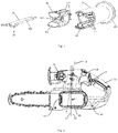
- Figures 1 and 2 show an electric chain saw 100 according to one embodiment of the present utility model, which comprises a housing 10, a working component extending outward from the housing 10, and a drive unit arranged in the housing for driving the working component, and a power supply device for providing electric energy to the drive unit.
- the working component of the electric chain saw comprises a chain 20 and a guide plate 21.
- One end of the guide plate 21 is supported in the housing 10, and the other end extends out of the housing 10 along a first axis L1.
- the chain 20 is sleeved on a sprocket (not shown in the figure) and the guide plate 21 so as to be guided along the edge of the guide plate.
- Saw blades are provided on the chain 20 for cutting.
- the guide plate 21 is designed to be able to move relative to the housing 10 along the first axis L1.
- the user firstly uses a wrench to loosen the fixing nut 22 on the cover plate 24, and then uses a screwdriver to turn the screw 23 clockwise or counterclockwise to move the guide plate 21 along the first axis L1, thereby tensioning or loosening the chain 20.
- the electric chain saw has a rear handle 30 (main handle) and a front handle 31 (auxiliary handle).
- the housing 10 is an assembly of two half shells, i.e., a left half and a right half, and comprises an upper part 11 and a lower part 12.
- the front handle 31 is located on the upper part 11 and extends to one side, and the chain 20 and the guide plate 21 protrude from the lower part 12.
- the rear handle 30 connects the upper part 11 and the lower part 12.
- the front handle 31 and/or the rear handle 30 may be independent components mounted on the housing, or may be integrally formed on the housing.
- Figure 3 shows one side of the electric chain saw, with the half shell on the side removed to show the components inside the housing.
- the drive unit comprises a motor 50, which may be a brushless DC motor, a brushed DC motor, an AC motor, etc.
- the motor 50 is controlled by a control unit, which can control the starting or stopping of the motor 50 in response to the user's operation of the trigger 61.
- At least part of the motor 50 of the electric chain saw is located in the upper part 11 of the housing 10.
- Figure 3 shows that the motor 50 is located between the front handle 31 and the rear handle 30. Preferably, at least part of the motor 50 is at the same height as the front handle 31. This arrangement makes full use of the internal space of the housing 10 and helps to reduce the overall size of the electric chain saw.
- Figure 3 also shows a motor holder 52, which encircles at least part of the motor 50 and is supported by the housing 10, and is used to fix the position of the motor 50.
- a shock absorber is provided between the motor 50 and the motor holder 52 or between the motor holder 52 and the housing 10 to prevent damages due to the large amplitude of the motor 50 rotating at a high speed.
- the motor 50 drives the sprocket to rotate through a transmission component.
- the transmission component comprises a reducing mechanism and a transmission mechanism.
- the reducing mechanism is connected to the output shaft of the motor to reduce the speed and increase the torque.
- the transmission mechanism is connected to the output end of the reducing mechanism and is used to transmit power to the sprocket.
- the reducing mechanism may be a planetary gear set 51 of at least one stage, or a gear set formed by meshing multiple gears of different sizes.
- the transmission mechanism may be bevel gears 53 and 54 or spur gears. It should be understood that the transmission component may comprise any mechanism that can convert the rotational movement of the output shaft of the motor to the rotational movement of the sprocket.
- the motor 50 rotates about a second axis L2.
- the second axis L2 is parallel to the first axis L1.
- the second axis L2 is at an angle with respect to the first axis L1.
- the angle ranges between 45° and 135°, being, for example, 60°, 70°, 80°, 90°, 100°, 110°, and 120°. More preferably, the angle is a right angle or an obtuse angle, i.e., the angle ranges between 90° and 135°.
- the angle is close to 90°, for example, from 90° to 110°, it means that the motor 50 is positioned essentially vertical in the housing, which allows the size of the upper part 11 of the housing to be reduced in the front-to-rear direction.
- the second axis L2 is preferably located on the plane where the guide plate 21 is located or parallel to the plane where the guide plate 21 is located. It should be understood that the above-mentioned parallelism does not mean being exactly parallel, but a range including being essentially parallel.
- the power supply device of the electric chain saw may be a battery 40 that allows charging for multiple times, which is mounted on the battery mounting portion 13 located on one side of the housing 10.
- the battery mounting part 13 is in a structure that fits the battery 40, and comprises a cavity for receiving the insert of the battery, a guide rail for guiding the sliding of the battery, etc.
- the battery mounting portion 13 is formed on one side of the lower part 12 of the housing 10. Viewed from the side, the motor 50 located in the upper part 11 of the housing 10 and the battery mounting portion 13 located on the lower part 12 of the housing 10 at least partially overlap, preferably essentially overlap, in the direction of the first axis L.
- the battery may be a universal battery pack that can be installed on other types of power tools and supply power to them.
- the battery is an 18V lithium-ion battery pack.
- the battery may have other nominal output voltages, for example, 12V, 14V, 24V, 36V, 40V, etc.
- the chain saw may also be a corded power tool, which is connected to a power source through a wire.
- Figure 4 is a top view of the electric chain saw, which shows the relative positions of the front handle 31, the rear handle 30, the battery 40, the chain 20, the guide plate 21, and the battery mounting portion 13.
- the central axis of the rear handle 30 is defined as a third axis L3.
- the first axis L1 is located on a first side of the third axis L3
- the front handle 31 is located on the opposite second side of the third axis L3.
- the battery mounting portion 13 is provided on the second side of the third axis L3.
- the distance d2 between the outer surface of the battery mounting portion 13 and the third axis L3 is greater than the distance d1 between the first axis L1 and the third axis L3.
- the distance d3 between the outer surface of the battery 40 and the third axis L3 is smaller than the distance d4 between the outermost end of the front handle 31 and the third axis L3.
- the centre of gravity of the entire chain saw will be located near the third axis L3, making it easier and more labour-saving for the user to control the chain saw.
- the user can still feel the good balance of the chain saw.
- Figure 5 shows the front handle 31, which is essentially cylindrical and has a first end 311 connected to the housing and an opposite second end 312.
- the second end 312 is a free end and is not connected to the housing.
- the front handle may be in another shape, for example, an L shape, U shape, etc.
- the front handle 31 is constructed to have a hollow space that can accommodate a tool 33. The user can take out the tool 33 from the front handle 31 when necessary, and put the tool 33 back into the front handle 31 after use. The tool can be taken out through an opening formed on the outer surface of the front handle, or by removing the front handle.
- an opening is formed at the second end 312 of the front handle 31, and the user can access the tool in the space and take it out through the second end 312.
- the tool 33 may be a flat wrench, which has a head 331 and a handle 332 and is used for loosening or tightening a nut, for example, the fixing nut 22 on the cover plate 24 shown in Figure 2 .
- the tool may be a screwdriver, a safety key, a lock key, etc., which can be used to implement some operations of the electric chain saw, for example, tensioning the chain, locking and unlocking, etc.
- two or more tools can be accommodated in the front handle. It is also conceivable that a single tool may perform two or more functions.
- the two ends of a tool may be respectively a wrench and a screwdriver.
- a tool holder 32 for holding the tool 33 may be provided in the front handle 31.
- the tool holder 32 shown in Figure 5 is mounted on the second end 312 of the front handle 31.
- a clamping portion 321 is formed at one end of the tool holder 32 for clamping the head 331 of the tool 33.
- a positioning member for example, a longitudinally extending rib 322, is formed on the outer wall of the tool holder 32, which fits a rib 313 formed on the inner wall of the front handle 31 to position the tool holder 32 at a predetermined position in the front handle 31.
- the tool holder 32 also defines a through hole 323 so that the handle 332 of the tool 33 can go through the tool holder 32 and enter the hollow space of the front handle 31.
- the user wants to replace the tool accommodated in the front handle but the shape or size of the new tool prevents it from being fixed to the tool holder 32, the user can remove the current tool holder and then mount another tool holder suitable for fixing the new tool on the second end 312 of the front handle 31.
- the tool holder itself can also be replaced to adapt to different tools.
- the control unit is integrated into the drive unit.
- the circuit board 60 of the control unit is provided at one end of the motor 50 and is located in the upper part 11 of the housing.
- the circuit board 60 may be directly or indirectly mounted on or connected to one end of the motor by any means, for example, connected by fasteners, fitted by clips, etc.
- the circuit board 60 is designed to be in a shape similar to the cross-sectional shape of the motor 50, for example, an essentially round shape, and is arranged coaxially with the motor 50. In this way, there is no need to reserve an extra space in the housing 10 for the circuit board, thereby further reducing the size of the housing.
- the control unit may be arranged on one side of the motor 50, in the rear handle 30, or in the lower part 12 of the housing at a position close to the battery mounting portion 13.
- Another advantage of integrating the control unit into the drive unit is to improve heat dissipation efficiency, because the motor and the circuit board can be cooled together.
- An air inlet and an air outlet are formed on the housing of the electric chain saw. The air enters the housing from the air inlet, flows through the motor to cool it, and is then discharged through the air outlet. Since the circuit board is placed at one end of the motor, the cooling air flowing into or out of the motor will also cool the circuit board.
- at least one of the air inlet and the air outlet is provided on the upper part of the housing.
- a fan may be installed in the housing close to the air inlet or the air outlet to facilitate drawing or discharging air to or from the housing.
- a radiator may be installed between the circuit board and the motor to further improve heat dissipation efficiency.
- Figure 6 is a side view of the electric chain saw with the battery 40 installed, wherein the upper part of the housing is removed to show the motor 50.
- the motor 50 is located above the battery 40, and the section of the rotation axis L2 of the motor 50 extending downward intersects with the battery 40.
- the front end 41 of the battery 40 is located below the front handle 31, and the rear end 42 is located below the trigger 61 on the rear handle 30.
- the vertical plane P1 where the centre of gravity G1 of the motor 50 is located is close to the vertical plane P2 where the centre of gravity G2 of the battery 40 is located, and the two vertical planes P1 and P2 are both located between the front handle 31 and the rear handle 30.
- the present utility model has improved the layout of the main components in an electric chain saw, especially the motor, battery, handle and control unit.
- the electric chain saw according to the present utility model has a smaller housing than conventional designs.
- the electric chain saw according to the present utility model optimizes the weight distribution of the main components, so that the user can operate the chain saw more stably and effortlessly, especially with both hands holding the front and rear handles of the chain saw at the same time.
Landscapes
- Life Sciences & Earth Sciences (AREA)
- Engineering & Computer Science (AREA)
- Mechanical Engineering (AREA)
- Wood Science & Technology (AREA)
- Forests & Forestry (AREA)
- Sawing (AREA)
Abstract
Description
- The present utility model relates to power tools, and in particular to an electric-powered chain saw and the layout of the main components thereof.
- Chain saws are one of the most commonly used power tools. An electric chain saw uses electricity as the power source to drive a motor, which moves a chain with cutting edges in a cyclic manner at a high speed for cutting. With the development of rechargeable battery technology, cordless electric chain saws that use battery packs as the power source have appeared on the market. In order to meet the need of long-time operation, more and more electric chain saws use large-capacity batteries.
- However, the motor, chain and other components of an electric chain saw are usually heavy, a large-capacity battery further increases the size and weight of the electric chain saw, and the user may feel tired after holding the electric chain saw for a long time, which reduces working efficiency and may cause safety issues.
- Targeting the above shortcomings in the prior art, the present utility model provides an electric chain saw with a compact structure and an ergonomic design for improving user experience.
- To achieve this, the present utility model provides a chain saw, comprising a housing, a drive unit accommodated in the housing and a chain driven by the drive unit, wherein the chain is provided on a guide plate extending from the housing outward along a first axis, the drive unit rotates about a second axis, and one end of a front handle is connected to the housing and the other end comprises a free end.
- Further, the second axis is on the plane where the guide plate is located or parallel to the plane where the guide plate is located, and optionally the second axis and the first axis form an angle. The angle ranges from 45° to 135°, preferably from 90° to 135°, and more preferably from 90° to 110°.
- Further, the chain saw further comprises a rear handle, the drive unit comprises a motor, and the motor is located between the front handle and the rear handle. Preferably, at least part of the motor is at the same height as the front handle.
- Further, the housing comprises an upper part and a lower part, wherein the front handle protrudes from the upper part, the guide plate protrudes from the lower part, the rear handle connects the upper part and the lower part, and at least part of the motor is located in the upper part.
- Further, a battery mounting portion is formed on the side of the housing. The motor and the battery mounting portion essentially overlap in the direction of the first axis.
- Further, the rear handle extends along a third axis. When viewed from above the chain saw, the first axis is located on a first side of the third axis, the front handle and the battery mounting portion are located on a second side of the third axis, and the first side is opposite to the second side.
- Further, the distance between the outer surface of the battery mounting portion and the third axis is greater than the distance between the first axis and the third axis.
- Further, the chain saw further comprises a battery that provides power to the motor. When viewed from one side of the chain saw, the motor is located above the battery, and preferably the front end of the battery is located below the front handle, and the rear and of the battery is located below the trigger of the rear handle. Preferably, the section of the second axis extending downward intersects with the battery.
- Further, the inside of the front handle defines a space for accommodating a tool, and the space can be accessed from the free end of the front handle.
- Further, the free end comprises a tool holder used to hold a tool, the tool holder is detachably mounted on the free end, and preferably a clamping portion is formed at one end of the tool holder, which is used to hold the head of a tool, and the tool holder defines a through hole, through which the handle of a tool enters the front handle.
- Further, the chain saw further comprises a control unit used to control the drive unit. The control unit comprises a circuit board, directly or indirectly mounted at one end of the drive unit, and preferably the circuit board and the drive unit are arranged coaxially.
- Further, at least one of an air inlet and an air outlet is formed on the housing. Air enters the housing through the air inlet, cools the drive unit and the circuit board, and is then discharged through the air outlet.
-
-
Figure 1 is a 3D view of the electric chain saw according to one embodiment of the present utility model. -
Figure 2 is another 3D view of the electric chain saw according to one embodiment of the present utility model. -
Figure 3 is a side view of the electric chain saw according to one embodiment of the present utility model. -
Figure 4 is a top view of the chain saw according to one embodiment of the present utility model. -
Figure 5 is an exploded view of the front handle of the electric chain saw according to one embodiment of the present utility model. -
Figure 6 is another side view of the electric chain saw according to one embodiment of the present utility model. - The utility model will be further described below in conjunction with the drawings and specific embodiments. It should be noted that terms indicating directions or positional relationships herein, such as "up", "down", "left", "right", "transverse", "longitudinal", "inner", "outer", "vertical", "horizontal", etc., are based only on the positions or positional relationships shown in the drawings, and are used only for the convenience of describing the utility model and simplifying the description. They do not indicate or imply that the devices/elements referred to must have a specific orientation or be constructed and operated in a specific orientation. Therefore, they may not be understood as limiting the utility model.
-
Figures 1 and 2 show an electric chain saw 100 according to one embodiment of the present utility model, which comprises ahousing 10, a working component extending outward from thehousing 10, and a drive unit arranged in the housing for driving the working component, and a power supply device for providing electric energy to the drive unit. - The working component of the electric chain saw comprises a
chain 20 and aguide plate 21. One end of theguide plate 21 is supported in thehousing 10, and the other end extends out of thehousing 10 along a first axis L1. Thechain 20 is sleeved on a sprocket (not shown in the figure) and theguide plate 21 so as to be guided along the edge of the guide plate. Saw blades are provided on thechain 20 for cutting. In order to adjust the tension of thechain 20, theguide plate 21 is designed to be able to move relative to thehousing 10 along the first axis L1. For the electric chain saw shown inFigures 1 and 2 , the user firstly uses a wrench to loosen thefixing nut 22 on thecover plate 24, and then uses a screwdriver to turn thescrew 23 clockwise or counterclockwise to move theguide plate 21 along the first axis L1, thereby tensioning or loosening thechain 20. - The electric chain saw has a rear handle 30 (main handle) and a front handle 31 (auxiliary handle). When operating the electric chain saw, the user may hold the
rear handle 30 and thefront handle 31 with both hands at the same time to obtain better stability during cutting. In this embodiment, thehousing 10 is an assembly of two half shells, i.e., a left half and a right half, and comprises anupper part 11 and alower part 12. Thefront handle 31 is located on theupper part 11 and extends to one side, and thechain 20 and theguide plate 21 protrude from thelower part 12. Therear handle 30 connects theupper part 11 and thelower part 12. Thefront handle 31 and/or therear handle 30 may be independent components mounted on the housing, or may be integrally formed on the housing. -
Figure 3 shows one side of the electric chain saw, with the half shell on the side removed to show the components inside the housing. In this embodiment, the drive unit comprises amotor 50, which may be a brushless DC motor, a brushed DC motor, an AC motor, etc. Themotor 50 is controlled by a control unit, which can control the starting or stopping of themotor 50 in response to the user's operation of thetrigger 61. - At least part of the
motor 50 of the electric chain saw is located in theupper part 11 of thehousing 10.Figure 3 shows that themotor 50 is located between thefront handle 31 and therear handle 30. Preferably, at least part of themotor 50 is at the same height as thefront handle 31. This arrangement makes full use of the internal space of thehousing 10 and helps to reduce the overall size of the electric chain saw.Figure 3 also shows amotor holder 52, which encircles at least part of themotor 50 and is supported by thehousing 10, and is used to fix the position of themotor 50. Optionally, a shock absorber is provided between themotor 50 and themotor holder 52 or between themotor holder 52 and thehousing 10 to prevent damages due to the large amplitude of themotor 50 rotating at a high speed. - The
motor 50 drives the sprocket to rotate through a transmission component. In this embodiment, the transmission component comprises a reducing mechanism and a transmission mechanism. The reducing mechanism is connected to the output shaft of the motor to reduce the speed and increase the torque. The transmission mechanism is connected to the output end of the reducing mechanism and is used to transmit power to the sprocket. The reducing mechanism may be a planetary gear set 51 of at least one stage, or a gear set formed by meshing multiple gears of different sizes. The transmission mechanism may bebevel gears - The
motor 50 rotates about a second axis L2. In some embodiments, viewed from one side of the electric chain saw, the second axis L2 is parallel to the first axis L1. However, in the embodiment shown inFigure 3 , the second axis L2 is at an angle with respect to the first axis L1. Preferably, the angle ranges between 45° and 135°, being, for example, 60°, 70°, 80°, 90°, 100°, 110°, and 120°. More preferably, the angle is a right angle or an obtuse angle, i.e., the angle ranges between 90° and 135°. In addition, if the angle is close to 90°, for example, from 90° to 110°, it means that themotor 50 is positioned essentially vertical in the housing, which allows the size of theupper part 11 of the housing to be reduced in the front-to-rear direction. In another aspect, the second axis L2 is preferably located on the plane where theguide plate 21 is located or parallel to the plane where theguide plate 21 is located. It should be understood that the above-mentioned parallelism does not mean being exactly parallel, but a range including being essentially parallel. - The power supply device of the electric chain saw may be a
battery 40 that allows charging for multiple times, which is mounted on thebattery mounting portion 13 located on one side of thehousing 10. Thebattery mounting part 13 is in a structure that fits thebattery 40, and comprises a cavity for receiving the insert of the battery, a guide rail for guiding the sliding of the battery, etc. In the embodiment shown inFigure 1 , thebattery mounting portion 13 is formed on one side of thelower part 12 of thehousing 10. Viewed from the side, themotor 50 located in theupper part 11 of thehousing 10 and thebattery mounting portion 13 located on thelower part 12 of thehousing 10 at least partially overlap, preferably essentially overlap, in the direction of the first axis L. - The battery may be a universal battery pack that can be installed on other types of power tools and supply power to them. In this embodiment, the battery is an 18V lithium-ion battery pack. In other embodiments, the battery may have other nominal output voltages, for example, 12V, 14V, 24V, 36V, 40V, etc. In an embodiment not shown, the chain saw may also be a corded power tool, which is connected to a power source through a wire.
-
Figure 4 is a top view of the electric chain saw, which shows the relative positions of thefront handle 31, therear handle 30, thebattery 40, thechain 20, theguide plate 21, and thebattery mounting portion 13. For ease of description, the central axis of therear handle 30 is defined as a third axis L3. Viewed from above, the first axis L1 is located on a first side of the third axis L3, and thefront handle 31 is located on the opposite second side of the third axis L3. Since the heavy components such as thechain 20, theguide plate 21 and the transmission system of the chain saw are all located on the first side of the third axis L3, the centre of gravity of the entire chain saw is biased to the first side of the third axis L3, and as a result the user needs to apply extra force when holding the chain saw to keep the chain saw balanced. For this reason, in this embodiment, thebattery mounting portion 13 is provided on the second side of the third axis L3. Preferably, the distance d2 between the outer surface of thebattery mounting portion 13 and the third axis L3 is greater than the distance d1 between the first axis L1 and the third axis L3. When thebattery 40 is installed, the distance d3 between the outer surface of thebattery 40 and the third axis L3 is smaller than the distance d4 between the outermost end of thefront handle 31 and the third axis L3. In this way, after the battery is installed, the centre of gravity of the entire chain saw will be located near the third axis L3, making it easier and more labour-saving for the user to control the chain saw. Even when a large-capacity battery pack is installed, the user can still feel the good balance of the chain saw. -
Figure 5 shows thefront handle 31, which is essentially cylindrical and has afirst end 311 connected to the housing and an oppositesecond end 312. In this embodiment, thesecond end 312 is a free end and is not connected to the housing. It should be understood that the front handle may be in another shape, for example, an L shape, U shape, etc. Thefront handle 31 is constructed to have a hollow space that can accommodate atool 33. The user can take out thetool 33 from thefront handle 31 when necessary, and put thetool 33 back into thefront handle 31 after use. The tool can be taken out through an opening formed on the outer surface of the front handle, or by removing the front handle. In the embodiment shown inFigure 5 , an opening is formed at thesecond end 312 of thefront handle 31, and the user can access the tool in the space and take it out through thesecond end 312. Thetool 33 may be a flat wrench, which has ahead 331 and ahandle 332 and is used for loosening or tightening a nut, for example, the fixingnut 22 on thecover plate 24 shown inFigure 2 . In other embodiments, the tool may be a screwdriver, a safety key, a lock key, etc., which can be used to implement some operations of the electric chain saw, for example, tensioning the chain, locking and unlocking, etc. In embodiments not shown, two or more tools can be accommodated in the front handle. It is also conceivable that a single tool may perform two or more functions. For example, the two ends of a tool may be respectively a wrench and a screwdriver. - Since an electric chain saw vibrates during operation, in order to prevent the
tool 33 from falling out of thefront handle 31, atool holder 32 for holding thetool 33 may be provided in thefront handle 31. Thetool holder 32 shown inFigure 5 is mounted on thesecond end 312 of thefront handle 31. A clampingportion 321 is formed at one end of thetool holder 32 for clamping thehead 331 of thetool 33. A positioning member, for example, alongitudinally extending rib 322, is formed on the outer wall of thetool holder 32, which fits arib 313 formed on the inner wall of thefront handle 31 to position thetool holder 32 at a predetermined position in thefront handle 31. It should be understood that other forms of positioning members are also feasible, as long as they can firmly fix the tool holder on the front handle. Thetool holder 32 also defines a throughhole 323 so that thehandle 332 of thetool 33 can go through thetool holder 32 and enter the hollow space of thefront handle 31. - If the user wants to replace the tool accommodated in the front handle but the shape or size of the new tool prevents it from being fixed to the
tool holder 32, the user can remove the current tool holder and then mount another tool holder suitable for fixing the new tool on thesecond end 312 of thefront handle 31. In other words, the tool holder itself can also be replaced to adapt to different tools. - With reference to
Figure 3 again, it shows a control unit of the electric chain saw. In this embodiment, the control unit is integrated into the drive unit. Specifically, thecircuit board 60 of the control unit is provided at one end of themotor 50 and is located in theupper part 11 of the housing. It should be understood that thecircuit board 60 may be directly or indirectly mounted on or connected to one end of the motor by any means, for example, connected by fasteners, fitted by clips, etc. Preferably, thecircuit board 60 is designed to be in a shape similar to the cross-sectional shape of themotor 50, for example, an essentially round shape, and is arranged coaxially with themotor 50. In this way, there is no need to reserve an extra space in thehousing 10 for the circuit board, thereby further reducing the size of the housing. In embodiments not shown, the control unit may be arranged on one side of themotor 50, in therear handle 30, or in thelower part 12 of the housing at a position close to thebattery mounting portion 13. - In addition to reducing the size to make the layout of the components in the housing more compact, another advantage of integrating the control unit into the drive unit is to improve heat dissipation efficiency, because the motor and the circuit board can be cooled together. An air inlet and an air outlet are formed on the housing of the electric chain saw. The air enters the housing from the air inlet, flows through the motor to cool it, and is then discharged through the air outlet. Since the circuit board is placed at one end of the motor, the cooling air flowing into or out of the motor will also cool the circuit board. Preferably, at least one of the air inlet and the air outlet is provided on the upper part of the housing. In order to accelerate the air flow, a fan may be installed in the housing close to the air inlet or the air outlet to facilitate drawing or discharging air to or from the housing. In addition, a radiator may be installed between the circuit board and the motor to further improve heat dissipation efficiency.
-
Figure 6 is a side view of the electric chain saw with thebattery 40 installed, wherein the upper part of the housing is removed to show themotor 50. Viewed from the side, themotor 50 is located above thebattery 40, and the section of the rotation axis L2 of themotor 50 extending downward intersects with thebattery 40. In this embodiment, thefront end 41 of thebattery 40 is located below thefront handle 31, and therear end 42 is located below thetrigger 61 on therear handle 30. With this arrangement, the vertical plane P1 where the centre of gravity G1 of themotor 50 is located is close to the vertical plane P2 where the centre of gravity G2 of thebattery 40 is located, and the two vertical planes P1 and P2 are both located between thefront handle 31 and therear handle 30. - In view of the above, the present utility model has improved the layout of the main components in an electric chain saw, especially the motor, battery, handle and control unit. In one aspect, the electric chain saw according to the present utility model has a smaller housing than conventional designs. In another aspect, the electric chain saw according to the present utility model optimizes the weight distribution of the main components, so that the user can operate the chain saw more stably and effortlessly, especially with both hands holding the front and rear handles of the chain saw at the same time.
- While the present utility model has been described in detail above with only certain embodiments, it should be understood that the present utility model is not limited to these disclosed embodiments. Those skilled in the art can envisage other embodiments that conform to the spirit and scope of the present utility model, including changes in quantities of components, alterations, substitutions or equivalent arrangements, and all such embodiments shall fall within the scope of the present utility model.
Claims (15)
- A chain saw, comprising a housing, a drive unit accommodated in the housing and a chain driven by the drive unit, wherein the chain is provided on a guide plate extending from the housing outward along a first axis, and the drive unit rotates about a second axis, and wherein,
the chain saw further comprises a front handle, wherein one end of the front handle is connected to the housing and the other end comprises a free end. - The chain saw as claimed in claim 1, wherein the second axis is on the plane where the guide plate is located or parallel to the plane where the guide plate is located, and optionally the second axis and the first axis form an angle.
- The chain saw as claimed in claim 2, wherein the angle ranges from 45°to 135°, preferably from 90° to 135°, and more preferably from 90° to 110°.
- The chain saw as claimed in any of the preceding claims, wherein the chain saw further comprises a rear handle, the drive unit comprises a motor, and the motor is located between the front handle and the rear handle.
- The chain saw as claimed in claim 4, wherein at least part of the motor is at the same height as the front handle.
- The chain saw as claimed in claim 4 or 5, wherein the housing comprises an upper part and a lower part, wherein the front handle protrudes from the upper part, the guide plate protrudes from the lower part, the rear handle connects the upper part and the lower part, and at least part of the motor is located in the upper part.
- The chain saw as claimed in any of the preceding claims, wherein a battery mounting portion is formed on one side of the housing.
- The chain saw as claimed in claim 7, wherein the motor and the battery mounting portion essentially overlap in the direction of the first axis.
- The chain saw as claimed in claim 7 or 8, wherein the rear handle extends along a third axis, when viewed from above the chain saw, the first axis is located on a first side of the third axis, the front handle and the battery mounting portion are located on a second side of the third axis, and the first side is opposite to the second side.
- The chain saw as claimed in claim 9, wherein the distance between the outer surface of the battery mounting portion and the third axis is greater than the distance between the first axis and the third axis.
- The chain saw as claimed in any of claims 4 to 6, wherein the chain saw further comprises a battery that provides power to the motor, when viewed from one side of the chain saw, the motor is located above the battery, preferably the front end of the battery is located below the front handle, the rear and of the battery is located below the trigger of the rear handle, and preferably the section of the second axis extending downward intersects with the battery.
- The chain saw as claimed in any of the preceding claims, wherein the inside of the front handle defines a space for accommodating a tool, and the space can be accessed from the free end of the front handle.
- The chain saw as claimed in claim 12, wherein the free end comprises a tool holder used to hold a tool, the tool holder is detachably mounted on the free end, and preferably a clamping portion is formed at one end of the tool holder, which is used to hold the head of a tool, and the tool holder defines a through hole, through which the handle of a tool enters the front handle.
- The chain saw as claimed in any of the preceding claims, wherein the chain saw further comprises a control unit used to control the drive unit, wherein the control unit comprises a circuit board, directly or indirectly mounted at one end of the drive unit, and preferably the circuit board and the drive unit are arranged coaxially.
- The chain saw as claimed in claim 14, wherein at least one of an air inlet and an air outlet is formed on the housing, wherein air enters the housing through the air inlet, cools the drive unit and the circuit board, and is then discharged through the air outlet.
Applications Claiming Priority (1)
| Application Number | Priority Date | Filing Date | Title |
|---|---|---|---|
| CN202120008909.7U CN214721118U (en) | 2021-01-05 | 2021-01-05 | chainsaw |
Publications (2)
| Publication Number | Publication Date |
|---|---|
| EP4032672A2 true EP4032672A2 (en) | 2022-07-27 |
| EP4032672A3 EP4032672A3 (en) | 2022-10-26 |
Family
ID=78637699
Family Applications (1)
| Application Number | Title | Priority Date | Filing Date |
|---|---|---|---|
| EP21217663.0A Pending EP4032672A3 (en) | 2021-01-05 | 2021-12-23 | Chain saw |
Country Status (3)
| Country | Link |
|---|---|
| EP (1) | EP4032672A3 (en) |
| CN (1) | CN214721118U (en) |
| AU (1) | AU2021290366B2 (en) |
Cited By (2)
| Publication number | Priority date | Publication date | Assignee | Title |
|---|---|---|---|---|
| DE102022214012A1 (en) * | 2022-12-20 | 2024-06-20 | Robert Bosch Gesellschaft mit beschränkter Haftung | chainsaw |
| WO2025228050A1 (en) * | 2024-04-30 | 2025-11-06 | 江苏东成机电工具有限公司 | Garden tool |
Families Citing this family (2)
| Publication number | Priority date | Publication date | Assignee | Title |
|---|---|---|---|---|
| CN118216326A (en) * | 2022-12-21 | 2024-06-21 | 南京泉峰科技有限公司 | Chain saw |
| CN223657216U (en) * | 2023-12-21 | 2025-12-12 | 宁波明军工贸有限公司 | Chain saw |
Citations (1)
| Publication number | Priority date | Publication date | Assignee | Title |
|---|---|---|---|---|
| US3857179A (en) * | 1974-04-22 | 1974-12-31 | Desa Industries | Chain saw |
Family Cites Families (1)
| Publication number | Priority date | Publication date | Assignee | Title |
|---|---|---|---|---|
| US9815220B2 (en) * | 2015-05-27 | 2017-11-14 | Dane Curtis Madson | Multi-function adjustable chainsaw |
-
2021
- 2021-01-05 CN CN202120008909.7U patent/CN214721118U/en active Active
- 2021-12-23 EP EP21217663.0A patent/EP4032672A3/en active Pending
- 2021-12-24 AU AU2021290366A patent/AU2021290366B2/en active Active
Patent Citations (1)
| Publication number | Priority date | Publication date | Assignee | Title |
|---|---|---|---|---|
| US3857179A (en) * | 1974-04-22 | 1974-12-31 | Desa Industries | Chain saw |
Cited By (3)
| Publication number | Priority date | Publication date | Assignee | Title |
|---|---|---|---|---|
| DE102022214012A1 (en) * | 2022-12-20 | 2024-06-20 | Robert Bosch Gesellschaft mit beschränkter Haftung | chainsaw |
| CN120390683A (en) * | 2022-12-20 | 2025-07-29 | 罗伯特·博世有限公司 | Chainsaw |
| WO2025228050A1 (en) * | 2024-04-30 | 2025-11-06 | 江苏东成机电工具有限公司 | Garden tool |
Also Published As
| Publication number | Publication date |
|---|---|
| AU2021290366A1 (en) | 2022-07-21 |
| AU2021290366B2 (en) | 2026-02-05 |
| EP4032672A3 (en) | 2022-10-26 |
| CN214721118U (en) | 2021-11-16 |
Similar Documents
| Publication | Publication Date | Title |
|---|---|---|
| AU2021290366B2 (en) | Chain saw | |
| US12090617B2 (en) | Power tool | |
| US20230271345A1 (en) | Handheld battery powered chainsaw | |
| US10220457B2 (en) | Cutting device | |
| US20200376705A1 (en) | Electric circular saw | |
| US20230405861A1 (en) | Working machine | |
| US9287751B2 (en) | Electric cutting or drilling tools that use battery packs as power sources | |
| US7768750B2 (en) | Cordless power tool | |
| JP5983929B2 (en) | Portable blower | |
| JP5979364B2 (en) | Portable blower | |
| CN213411880U (en) | Cutting tool | |
| CN113649642B (en) | Circular Saw | |
| US11559916B2 (en) | Electric working machine | |
| JP2014147353A (en) | Electric lawn mower | |
| US9876201B2 (en) | Electric working machine and electric working machine system | |
| JP6942515B2 (en) | Electrical equipment | |
| CN111376351A (en) | chainsaw | |
| JP2019030946A (en) | Rechargeable polisher | |
| CN103659752A (en) | Power tools | |
| CN112077799B (en) | An electric tool | |
| CN218638612U (en) | Angle drill | |
| CN208084537U (en) | Electric circular saw | |
| US12558766B2 (en) | Percussion tool | |
| CN219404094U (en) | Large impact wrench powered by battery | |
| US11396111B2 (en) | Thickness planer |
Legal Events
| Date | Code | Title | Description |
|---|---|---|---|
| PUAI | Public reference made under article 153(3) epc to a published international application that has entered the european phase |
Free format text: ORIGINAL CODE: 0009012 |
|
| STAA | Information on the status of an ep patent application or granted ep patent |
Free format text: STATUS: THE APPLICATION HAS BEEN PUBLISHED |
|
| AK | Designated contracting states |
Kind code of ref document: A2 Designated state(s): AL AT BE BG CH CY CZ DE DK EE ES FI FR GB GR HR HU IE IS IT LI LT LU LV MC MK MT NL NO PL PT RO RS SE SI SK SM TR |
|
| PUAL | Search report despatched |
Free format text: ORIGINAL CODE: 0009013 |
|
| AK | Designated contracting states |
Kind code of ref document: A3 Designated state(s): AL AT BE BG CH CY CZ DE DK EE ES FI FR GB GR HR HU IE IS IT LI LT LU LV MC MK MT NL NO PL PT RO RS SE SI SK SM TR |
|
| RIC1 | Information provided on ipc code assigned before grant |
Ipc: B25F 5/02 20060101ALI20220921BHEP Ipc: B27B 17/08 20060101ALI20220921BHEP Ipc: B27B 17/00 20060101AFI20220921BHEP |
|
| STAA | Information on the status of an ep patent application or granted ep patent |
Free format text: STATUS: REQUEST FOR EXAMINATION WAS MADE |
|
| 17P | Request for examination filed |
Effective date: 20230424 |
|
| RBV | Designated contracting states (corrected) |
Designated state(s): AL AT BE BG CH CY CZ DE DK EE ES FI FR GB GR HR HU IE IS IT LI LT LU LV MC MK MT NL NO PL PT RO RS SE SI SK SM TR |
|
| STAA | Information on the status of an ep patent application or granted ep patent |
Free format text: STATUS: EXAMINATION IS IN PROGRESS |
|
| 17Q | First examination report despatched |
Effective date: 20250429 |