EP4032619A1 - Mesh type atomizer using porous thin film and method for manufacturing the same - Google Patents
Mesh type atomizer using porous thin film and method for manufacturing the same Download PDFInfo
- Publication number
- EP4032619A1 EP4032619A1 EP21193052.4A EP21193052A EP4032619A1 EP 4032619 A1 EP4032619 A1 EP 4032619A1 EP 21193052 A EP21193052 A EP 21193052A EP 4032619 A1 EP4032619 A1 EP 4032619A1
- Authority
- EP
- European Patent Office
- Prior art keywords
- thin film
- porous thin
- nozzle area
- mesh type
- type atomizer
- Prior art date
- Legal status (The legal status is an assumption and is not a legal conclusion. Google has not performed a legal analysis and makes no representation as to the accuracy of the status listed.)
- Granted
Links
Images



Classifications
-
- A—HUMAN NECESSITIES
- A61—MEDICAL OR VETERINARY SCIENCE; HYGIENE
- A61M—DEVICES FOR INTRODUCING MEDIA INTO, OR ONTO, THE BODY; DEVICES FOR TRANSDUCING BODY MEDIA OR FOR TAKING MEDIA FROM THE BODY; DEVICES FOR PRODUCING OR ENDING SLEEP OR STUPOR
- A61M11/00—Sprayers or atomisers specially adapted for therapeutic purposes
- A61M11/001—Particle size control
- A61M11/003—Particle size control by passing the aerosol trough sieves or filters
-
- A—HUMAN NECESSITIES
- A61—MEDICAL OR VETERINARY SCIENCE; HYGIENE
- A61M—DEVICES FOR INTRODUCING MEDIA INTO, OR ONTO, THE BODY; DEVICES FOR TRANSDUCING BODY MEDIA OR FOR TAKING MEDIA FROM THE BODY; DEVICES FOR PRODUCING OR ENDING SLEEP OR STUPOR
- A61M11/00—Sprayers or atomisers specially adapted for therapeutic purposes
- A61M11/005—Sprayers or atomisers specially adapted for therapeutic purposes using ultrasonics
-
- A—HUMAN NECESSITIES
- A61—MEDICAL OR VETERINARY SCIENCE; HYGIENE
- A61M—DEVICES FOR INTRODUCING MEDIA INTO, OR ONTO, THE BODY; DEVICES FOR TRANSDUCING BODY MEDIA OR FOR TAKING MEDIA FROM THE BODY; DEVICES FOR PRODUCING OR ENDING SLEEP OR STUPOR
- A61M15/00—Inhalators
- A61M15/0085—Inhalators using ultrasonics
-
- B—PERFORMING OPERATIONS; TRANSPORTING
- B05—SPRAYING OR ATOMISING IN GENERAL; APPLYING FLUENT MATERIALS TO SURFACES, IN GENERAL
- B05B—SPRAYING APPARATUS; ATOMISING APPARATUS; NOZZLES
- B05B17/00—Apparatus for spraying or atomising liquids or other fluent materials, not covered by the preceding groups
- B05B17/04—Apparatus for spraying or atomising liquids or other fluent materials, not covered by the preceding groups operating with special methods
- B05B17/06—Apparatus for spraying or atomising liquids or other fluent materials, not covered by the preceding groups operating with special methods using ultrasonic or other kinds of vibrations
- B05B17/0607—Apparatus for spraying or atomising liquids or other fluent materials, not covered by the preceding groups operating with special methods using ultrasonic or other kinds of vibrations generated by electrical means, e.g. piezoelectric transducers
- B05B17/0615—Apparatus for spraying or atomising liquids or other fluent materials, not covered by the preceding groups operating with special methods using ultrasonic or other kinds of vibrations generated by electrical means, e.g. piezoelectric transducers spray being produced at the free surface of the liquid or other fluent material in a container and subjected to the vibrations
-
- B—PERFORMING OPERATIONS; TRANSPORTING
- B05—SPRAYING OR ATOMISING IN GENERAL; APPLYING FLUENT MATERIALS TO SURFACES, IN GENERAL
- B05B—SPRAYING APPARATUS; ATOMISING APPARATUS; NOZZLES
- B05B17/00—Apparatus for spraying or atomising liquids or other fluent materials, not covered by the preceding groups
- B05B17/04—Apparatus for spraying or atomising liquids or other fluent materials, not covered by the preceding groups operating with special methods
- B05B17/06—Apparatus for spraying or atomising liquids or other fluent materials, not covered by the preceding groups operating with special methods using ultrasonic or other kinds of vibrations
- B05B17/0607—Apparatus for spraying or atomising liquids or other fluent materials, not covered by the preceding groups operating with special methods using ultrasonic or other kinds of vibrations generated by electrical means, e.g. piezoelectric transducers
- B05B17/0638—Apparatus for spraying or atomising liquids or other fluent materials, not covered by the preceding groups operating with special methods using ultrasonic or other kinds of vibrations generated by electrical means, e.g. piezoelectric transducers spray being produced by discharging the liquid or other fluent material through a plate comprising a plurality of orifices
- B05B17/0646—Vibrating plates, i.e. plates being directly subjected to the vibrations, e.g. having a piezoelectric transducer attached thereto
-
- C—CHEMISTRY; METALLURGY
- C25—ELECTROLYTIC OR ELECTROPHORETIC PROCESSES; APPARATUS THEREFOR
- C25D—PROCESSES FOR THE ELECTROLYTIC OR ELECTROPHORETIC PRODUCTION OF COATINGS; ELECTROFORMING; APPARATUS THEREFOR
- C25D11/00—Electrolytic coating by surface reaction, i.e. forming conversion layers
- C25D11/02—Anodisation
- C25D11/04—Anodisation of aluminium or alloys based thereon
- C25D11/18—After-treatment, e.g. pore-sealing
-
- C—CHEMISTRY; METALLURGY
- C25—ELECTROLYTIC OR ELECTROPHORETIC PROCESSES; APPARATUS THEREFOR
- C25D—PROCESSES FOR THE ELECTROLYTIC OR ELECTROPHORETIC PRODUCTION OF COATINGS; ELECTROFORMING; APPARATUS THEREFOR
- C25D11/00—Electrolytic coating by surface reaction, i.e. forming conversion layers
- C25D11/02—Anodisation
- C25D11/04—Anodisation of aluminium or alloys based thereon
- C25D11/18—After-treatment, e.g. pore-sealing
- C25D11/20—Electrolytic after-treatment
-
- C—CHEMISTRY; METALLURGY
- C25—ELECTROLYTIC OR ELECTROPHORETIC PROCESSES; APPARATUS THEREFOR
- C25D—PROCESSES FOR THE ELECTROLYTIC OR ELECTROPHORETIC PRODUCTION OF COATINGS; ELECTROFORMING; APPARATUS THEREFOR
- C25D5/00—Electroplating characterised by the process; Pretreatment or after-treatment of workpieces
- C25D5/02—Electroplating of selected surface areas
-
- A—HUMAN NECESSITIES
- A61—MEDICAL OR VETERINARY SCIENCE; HYGIENE
- A61M—DEVICES FOR INTRODUCING MEDIA INTO, OR ONTO, THE BODY; DEVICES FOR TRANSDUCING BODY MEDIA OR FOR TAKING MEDIA FROM THE BODY; DEVICES FOR PRODUCING OR ENDING SLEEP OR STUPOR
- A61M2205/00—General characteristics of the apparatus
- A61M2205/02—General characteristics of the apparatus characterised by a particular materials
- A61M2205/0211—Ceramics
-
- A—HUMAN NECESSITIES
- A61—MEDICAL OR VETERINARY SCIENCE; HYGIENE
- A61M—DEVICES FOR INTRODUCING MEDIA INTO, OR ONTO, THE BODY; DEVICES FOR TRANSDUCING BODY MEDIA OR FOR TAKING MEDIA FROM THE BODY; DEVICES FOR PRODUCING OR ENDING SLEEP OR STUPOR
- A61M2205/00—General characteristics of the apparatus
- A61M2205/02—General characteristics of the apparatus characterised by a particular materials
- A61M2205/0238—General characteristics of the apparatus characterised by a particular materials the material being a coating or protective layer
-
- A—HUMAN NECESSITIES
- A61—MEDICAL OR VETERINARY SCIENCE; HYGIENE
- A61M—DEVICES FOR INTRODUCING MEDIA INTO, OR ONTO, THE BODY; DEVICES FOR TRANSDUCING BODY MEDIA OR FOR TAKING MEDIA FROM THE BODY; DEVICES FOR PRODUCING OR ENDING SLEEP OR STUPOR
- A61M2207/00—Methods of manufacture, assembly or production
-
- C—CHEMISTRY; METALLURGY
- C25—ELECTROLYTIC OR ELECTROPHORETIC PROCESSES; APPARATUS THEREFOR
- C25D—PROCESSES FOR THE ELECTROLYTIC OR ELECTROPHORETIC PRODUCTION OF COATINGS; ELECTROFORMING; APPARATUS THEREFOR
- C25D11/00—Electrolytic coating by surface reaction, i.e. forming conversion layers
- C25D11/02—Anodisation
- C25D11/04—Anodisation of aluminium or alloys based thereon
Definitions
- the present disclosure relates to an atomizer, and more particularly, to a mesh type atomizer for atomizing a liquid into nanometer-level fine particles using a porous thin film including holes having nanometer diameters.
- a medical nebulizer is equipped with an atomizer for atomizing liquid medicine into fine particles floating in the air that a patient can inhale through the respiratory system.
- the atomizer may be largely classified into an air jet atomizer, an ultrasonic wave atomizer and a vibrating mesh atomizer according to the liquid atomization mechanism.
- the air jet atomizer sprays a jet of compressed air to the surface of liquid medicine located at the base and forces the medicine floating in the air through nozzles
- the ultrasonic wave atomizer emits ultrasonic waves to the surface of liquid medicine to give vibrations and forces the medicine floating in the air through nozzles. Since the air jet or ultrasonic wave atomizer pushes droplets by mechanical striking, the atomized particle size is not uniform and it is difficult to reduce droplets to a predetermined size or less, resulting in a low rate of absorption into the respiratory system.
- the vibrating mesh atomizer reduces liquid medicine to fine particles through a mesh having very small holes, and causes vibration to release the particles into the air.
- the common vibrating mesh atomizer includes a mesh thin film for producing very small droplets and an ultrasonic transducer for giving ultrasonic vibrations to the mesh thin film to cause the ejection of the droplets.
- the vibrating mesh atomizer has a uniform hole diameter of the mesh, and thus can form uniform particles compared to the air jet or ultrasonic wave atomizer.
- the mesh thin film is usually made through laser drilling (drilling of holes in the thin film by micro-laser irradiation), and a minimum size of hole that can be machined using a laser is about 2.5 micrometers.
- the size of particle atomized through the mesh is at least twice larger than the mesh hole size, so the atomized particle is a minimum of 5 micrometers in size.
- Japanese Patent No. 6415953 discloses a mesh manufactured by forming holes having the diameter of 3 to 25 micrometers in a substrate through laser drilling, for use in a liquid atomizer.
- nebulizers Most of medical nebulizers have been developed for asthma patients and medicines for asthma patients are designed to be absorbed into larynx. Since the size of a particle that can be absorbed in larynx is about 4.7 to 7 micrometers, the existing atomizers that produce droplets of about 5 micrometers can be sufficiently used.
- the size of a particle that can be absorbed in lungs is about 0.65 to 1.1 micrometers (i.e., a nanometer level) in size, which is smaller than the size of a particle that can be absorbed in larynx or other organs.
- the existing atomizer mesh manufactured by laser drilling is impossible to produce nanometer sized particles due to the technical limitation, and thus cannot be used for the treatment of lung diseases.
- the present disclosure is directed to providing a mesh type atomizer for atomizing a liquid into nanometer sized fine particles using a porous thin film as a mesh and a method for manufacturing the same.
- a mesh type atomizer includes a porous thin film having a multi-hole structure, a metal layer covering a remaining area except a nozzle area in which droplets are sprayed through the holes on a surface of the porous thin film, and an ultrasonic transducer to output ultrasonic waves to vibrate the porous thin film.
- the hole in the remaining area except the nozzle area may be, at least in part, filled with a metal material.
- the hole of the porous thin film may be a few nanometers to a few micrometers in diameter.
- the porous thin film is anodic aluminum oxide.
- the nozzle area may include at least one hole, and the droplet sprayed through the nozzle area may be a few nanometers to a few micrometers in diameter.
- a distance between the nozzle area and an adjacent nozzle area may be set to prevent the droplets sprayed in each nozzle area from merging.
- a method for manufacturing a mesh type atomizer includes providing a porous thin film having a multi-hole structure, forming a photosensitive layer in a nozzle area in which droplets are to be sprayed through the holes on a surface of the porous thin film, depositing a metal layer on the porous thin film and the photosensitive layer, removing the photosensitive layer from the porous thin film, and combining an ultrasonic transducer with the porous thin film.
- the method for manufacturing a mesh type atomizer may further include, after depositing the metal layer on the porous thin film and the photosensitive layer, connecting an electroplating metal material to the metal layer, and growing a metal material in the hole of a remaining area except the nozzle area through electroplating.
- a liquid may be atomized into nanometer-level fine particles using the porous thin film including nanometer sized holes.
- the size of particles that can be formed by the existing mesh type atomizers manufactured by laser drilling is a few micrometers or more, absorption of liquid medicine into lungs is disallowed.
- the sprayed droplet size may be precisely adjusted by setting the shape, size and interval of the nozzle according to the atomizer manufacturing process, and the strength of the mesh may be selectively increased by growing the metal material in the hole of the porous thin film through electroplating.
- the embodiments may be applied in various technical fields including, but not limited to, medical fields.
- medical fields including, but not limited to, medical fields.
- FIG. 1 shows the structure of a mesh type atomizer according to an embodiment.
- the atomizer 1 according to an embodiment includes a mesh structure 10 for breaking up a liquid into fine particles and an ultrasonic transducer 20 for vibrating the mesh structure 10 using ultrasonic waves.
- the mesh structure 10 may be divided into at least one nozzle area A where droplets are sprayed and a remaining area B covered with a metal layer.
- the mesh type atomizer may further include essential or optional elements for its operation.
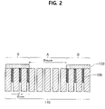
- FIG. 2 is a cross-sectional view of the mesh structure used in the mesh type atomizer according to an embodiment.
- the mesh structure includes a porous thin film 110 having a multi-hole structure and a metal layer 120 that covers the remaining area B except the nozzle area A where droplets are sprayed through the holes on the surface of the porous thin film 110.
- the hole in the remaining area B except the nozzle area A may be, at least in part, filled with a metal material 130.
- FIG. 3 shows the porous thin film used to manufacture the mesh structure according to an embodiment.
- the porous thin film 110 includes a plurality of holes having very small diameters of a few nanometers to a few micrometers.
- anodic aluminum oxide having nanometer sized holes may be used.
- the type of the porous thin film or the size of the hole is not limited thereto and various types of porous thin films having holes of various sizes may be used.
- the metal layer 120 covers the remaining area B except the nozzle area A where droplets are sprayed through the holes on the surface of the porous thin film 110. Since the remaining area B is blocked by the metal layer 120, a liquid is only sprayed through the nozzle area A.
- the nozzle area A includes at least one hole, and the droplet sprayed through the nozzle area A has a very small size on the level of a few nanometers to a few micrometers. The droplet size may vary depending on the number of holes in the nozzle area A and the diameter of each hole.
- the size of a droplet passing through a hole is about twice larger than the diameter of the hole, and may become larger when the droplet and droplets of adjacent holes merge, so the actually sprayed droplet size is not equal to the hole size, but the sprayed droplet size may be adjusted by adjusting the size of the nozzle area in the mesh manufacturing process.
- nanometer sized droplets may be formed by using the porous thin film (AAO) including nanometer-level holes and limiting the size of the nozzle.
- the holes in the area B other than the nozzle may be partially filled with the metal material 130 to increase the strength of the mesh or selectively adjust the ultrasonic resonant frequency.
- the metal material in the hole may be grown using electroplating.
- the distance between a nozzle area and its adjacent nozzle area is indicated in T, and the diameter of the nozzle area is indicated in d nozzle .
- the distance T between the nozzle areas may be set to an optimal distance to prevent droplets sprayed in each nozzle area from merging.
- the diameter d nozzle of the nozzle area may be set, taking the sprayed droplet size into account. That is, the diameter may be set to a larger value to make droplets larger, or may be set to a smaller value to make droplets smaller.
- the ultrasonic transducer 20 outputs ultrasonic waves to vibrate the mesh structure 10. As shown in FIG. 1 , the ring type ultrasonic transducer 20 attached to the edge of the mesh structure 10 may be used.
- the mesh structure 10 vibrates by the ultrasonic waves outputted from the ultrasonic transducer 20, and atomizes a liquid into fine particles (preferably, droplets having nanometer diameters).
- a porous thin film 110 having a multi-hole structure is provided as shown in FIG. 4A .
- the porous thin film 110 includes a plurality of holes, and the diameter dpore of each hole may be a few nanometers to a few micrometers.
- anodic aluminum oxide having nanometer-sized holes may be used as the porous thin film 110.
- a photosensitive layer 111 is formed on a part of the surface of the porous thin film 110 as shown in FIG. 4B .
- An area having the photosensitive layer is a nozzle area where droplets will be sprayed through the holes.
- a metal layer 120 is deposited, covering the porous thin film 110 and the photosensitive layer 111 as shown in FIG. 4C .
- the metal layer 120 may be deposited using the existing thin film deposition process, for example, chemical vapor deposition (CVD) and physical vapor deposition (PVD).
- the photosensitive layer 111 is removed from the porous thin film 110 to form a mesh structure.
- the area A in which the photosensitive layer 111 has been formed is exposed and the remaining area B is covered with the metal layer 120.
- the area A is the nozzle area where droplets are sprayed through the holes.
- the mesh structure 10 is formed through the process of FIGS. 4A to 4D , and an ultrasonic transducer 20 is combined with the mesh structure 10 to manufacture an atomizer according to an embodiment as shown in FIG. 4E .
- the ring type ultrasonic transducer 20 may be used.
- FIGS. 5A and 5B are diagrams for describing a method for manufacturing a mesh structure with increased strength according to an embodiment.
- FIGS. 4A to 4C the process of FIGS. 4A to 4C is performed in the same way as the previous embodiment.
- the metal layer 120 and an electroplating metal material 121 are connected through an electrode as shown in FIG. 5A .
- the type of the electroplating metal material 121 may vary depending on the type of metal of which the metal layer 120 is made.
- a metal material 130 is grown in the hole through oxidation and reduction of metal ions in an electrolyte as shown in FIG. 5B .
- the metal material is not grown in the area having the photosensitive layer 111 (later formed as the nozzle area), and the metal material in the hole is only grown in the remaining area. Accordingly, it is possible to increase the strength of the mesh structure while not inhibiting the liquid atomization function of the porous thin film.
- FIGS. 6A and 6B are cross-sectional views of the mesh structure with increased strength according to an embodiment.
- the metal material 130 may be grown in the hole of the porous thin film 110 through electroplating, and the height tmetai of the metal material 130 may be adjusted by adjusting the electroplating process time.
- FIG. 6A shows that the hole is partially filled with the metal material 130
- FIG. 6B shows that the hole is fully filled with the metal material 130.
- the strength of the mesh structure may be adjusted by selectively adjusting the thickness of the metal material, thereby selectively adjusting the ultrasonic resonant frequency.
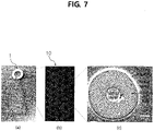
- FIG. 7 shows a photographic image of the mesh type atomizer manufactured according to an embodiment and a scanning electron microscope (SEM) image of the nozzle area having the porous thin film structure.
- A shows the whole structure of the mesh type atomizer 1.
- B is an enlarged photographic image of the mesh structure 10 of the atomizer, and
- C is an enlarged photographic image of one of the nozzle areas A included in the mesh structure.
- one nozzle area includes a plurality of nanometer sized holes through which fine droplets having the size of a few nanometers are sprayed.
- the area other than the nozzle area is covered with the metal layer and droplets are not sprayed there.
- the mesh type atomizer described hereinabove it is possible to atomize a liquid into nanometer-level fine particles using the porous thin film including the nanometer sized holes. It is possible to precisely adjust the sprayed droplet size by setting the shape, size and interval of the nozzle in the manufacturing process, and it is possible to selectively increase the strength of the mesh by growing the metal material in the hole of the porous thin film through electroplating. It is possible to form much smaller droplets compared to the existing mesh drilled by laser drilling, and it can be used in various technical fields including medical nebulizers used to administer fine drug particles, fuel injection systems of automotive engines, filters or the like.
Landscapes
- Health & Medical Sciences (AREA)
- Engineering & Computer Science (AREA)
- Chemical & Material Sciences (AREA)
- General Health & Medical Sciences (AREA)
- Veterinary Medicine (AREA)
- Hematology (AREA)
- Life Sciences & Earth Sciences (AREA)
- Animal Behavior & Ethology (AREA)
- Anesthesiology (AREA)
- Public Health (AREA)
- Heart & Thoracic Surgery (AREA)
- Biomedical Technology (AREA)
- Organic Chemistry (AREA)
- Metallurgy (AREA)
- Chemical Kinetics & Catalysis (AREA)
- Electrochemistry (AREA)
- Materials Engineering (AREA)
- Dispersion Chemistry (AREA)
- Pulmonology (AREA)
- Bioinformatics & Cheminformatics (AREA)
- Physics & Mathematics (AREA)
- Special Spraying Apparatus (AREA)
- Optics & Photonics (AREA)
- Mechanical Engineering (AREA)
- Nozzles (AREA)
- Plasma & Fusion (AREA)
- Electromagnetism (AREA)
- Toxicology (AREA)
Abstract
Description
- This application claims priority to
Korean Patent Application No. 10-2021-0010201, filed on January 25, 2021 - The present disclosure relates to an atomizer, and more particularly, to a mesh type atomizer for atomizing a liquid into nanometer-level fine particles using a porous thin film including holes having nanometer diameters.
- This research is conducted by Korea Institute of Science and Technology under the support of collaborative life-cycle medical device R&D project (Development of capacitive micromachined ultrasonic transducer for MR-compatible functional multimodal imaging and treatment: 2M35810) of the Ministry of Trade, Industry and Energy and innovation challenge pilot project (Development of ultrasonic probe and attachable device using semiconductor technology, Project Series No.: 2N59660) of the Ministry of Science and ICT.
- A medical nebulizer is equipped with an atomizer for atomizing liquid medicine into fine particles floating in the air that a patient can inhale through the respiratory system. The atomizer may be largely classified into an air jet atomizer, an ultrasonic wave atomizer and a vibrating mesh atomizer according to the liquid atomization mechanism. The air jet atomizer sprays a jet of compressed air to the surface of liquid medicine located at the base and forces the medicine floating in the air through nozzles, and the ultrasonic wave atomizer emits ultrasonic waves to the surface of liquid medicine to give vibrations and forces the medicine floating in the air through nozzles. Since the air jet or ultrasonic wave atomizer pushes droplets by mechanical striking, the atomized particle size is not uniform and it is difficult to reduce droplets to a predetermined size or less, resulting in a low rate of absorption into the respiratory system.
- The vibrating mesh atomizer reduces liquid medicine to fine particles through a mesh having very small holes, and causes vibration to release the particles into the air. The common vibrating mesh atomizer includes a mesh thin film for producing very small droplets and an ultrasonic transducer for giving ultrasonic vibrations to the mesh thin film to cause the ejection of the droplets. The vibrating mesh atomizer has a uniform hole diameter of the mesh, and thus can form uniform particles compared to the air jet or ultrasonic wave atomizer.
- The mesh thin film is usually made through laser drilling (drilling of holes in the thin film by micro-laser irradiation), and a minimum size of hole that can be machined using a laser is about 2.5 micrometers. The size of particle atomized through the mesh is at least twice larger than the mesh hole size, so the atomized particle is a minimum of 5 micrometers in size.
-
Japanese Patent No. 6415953 - Most of medical nebulizers have been developed for asthma patients and medicines for asthma patients are designed to be absorbed into larynx. Since the size of a particle that can be absorbed in larynx is about 4.7 to 7 micrometers, the existing atomizers that produce droplets of about 5 micrometers can be sufficiently used.
- However, in the case of lung disease patients, it is required that medicine is absorbed into lungs to obtain the medicine's definite effects, and the size of a particle that can be absorbed in lungs is about 0.65 to 1.1 micrometers (i.e., a nanometer level) in size, which is smaller than the size of a particle that can be absorbed in larynx or other organs. However, the existing atomizer mesh manufactured by laser drilling is impossible to produce nanometer sized particles due to the technical limitation, and thus cannot be used for the treatment of lung diseases.
- The present disclosure is directed to providing a mesh type atomizer for atomizing a liquid into nanometer sized fine particles using a porous thin film as a mesh and a method for manufacturing the same.
- A mesh type atomizer according to an embodiment includes a porous thin film having a multi-hole structure, a metal layer covering a remaining area except a nozzle area in which droplets are sprayed through the holes on a surface of the porous thin film, and an ultrasonic transducer to output ultrasonic waves to vibrate the porous thin film.
- According to an embodiment, the hole in the remaining area except the nozzle area may be, at least in part, filled with a metal material.
- According to an embodiment, the hole of the porous thin film may be a few nanometers to a few micrometers in diameter.
- According to an embodiment, the porous thin film is anodic aluminum oxide.
- According to an embodiment, the nozzle area may include at least one hole, and the droplet sprayed through the nozzle area may be a few nanometers to a few micrometers in diameter.
- According to an embodiment, a distance between the nozzle area and an adjacent nozzle area may be set to prevent the droplets sprayed in each nozzle area from merging.
- A method for manufacturing a mesh type atomizer according to an embodiment includes providing a porous thin film having a multi-hole structure, forming a photosensitive layer in a nozzle area in which droplets are to be sprayed through the holes on a surface of the porous thin film, depositing a metal layer on the porous thin film and the photosensitive layer, removing the photosensitive layer from the porous thin film, and combining an ultrasonic transducer with the porous thin film.
- According to an embodiment, the method for manufacturing a mesh type atomizer may further include, after depositing the metal layer on the porous thin film and the photosensitive layer, connecting an electroplating metal material to the metal layer, and growing a metal material in the hole of a remaining area except the nozzle area through electroplating.
- Using the atomizer according to an embodiment, a liquid may be atomized into nanometer-level fine particles using the porous thin film including nanometer sized holes. As the size of particles that can be formed by the existing mesh type atomizers manufactured by laser drilling is a few micrometers or more, absorption of liquid medicine into lungs is disallowed. In contrast, according to an embodiment, it is possible to atomize liquid medicine into nanometer sized particles which can be directly absorbed into lungs, and thus it can be advantageously used for the treatment of lung diseases.
- Additionally, the sprayed droplet size may be precisely adjusted by setting the shape, size and interval of the nozzle according to the atomizer manufacturing process, and the strength of the mesh may be selectively increased by growing the metal material in the hole of the porous thin film through electroplating.
- The embodiments may be applied in various technical fields including, but not limited to, medical fields. For example, when applied to automotive engines, it is possible to increase the complete combustion efficiency of fuel by spraying fine fuel particles compared to the conventional art, and when applied in chemical fields, it may be used to generate or filter nanometer sized particles.
- The following is a brief introduction to necessary drawings in the description of the embodiments to describe the technical solutions of the embodiments of the present disclosure or the existing technology more clearly. It should be understood that the accompanying drawings are for the purpose of describing the embodiments of the present disclosure and are not intended to be limiting of the present disclosure. Additionally, for clarity of description, illustration of some elements in the accompanying drawings may be exaggerated and omitted.
-
FIG. 1 shows the structure of a mesh type atomizer according to an embodiment. -
FIG. 2 is a cross-sectional view of a mesh structure used in a mesh type atomizer according to an embodiment. -
FIG. 3 shows a porous thin film used to manufacture a mesh structure according to an embodiment. -
FIGS. 4A to 4E are diagrams for describing a method for manufacturing a mesh type atomizer according to an embodiment. -
FIGS. 5A and5B are diagrams for describing a method for manufacturing a mesh structure with increased strength according to an embodiment. -
FIGS. 6A and 6B are cross-sectional views of a mesh structure with increased strength according to an embodiment. -
FIG. 7 shows a photographic image of a mesh type atomizer manufactured according to an embodiment and a scanning electron microscope (SEM) image of a nozzle area made of a porous thin film. - The following detailed description of the present disclosure is made with reference to the accompanying drawings, in which particular embodiments for practicing the present disclosure are shown for illustration purposes. These embodiments are described in sufficiently detail for those skilled in the art to practice the present disclosure. It should be understood that various embodiments of the present disclosure are different but do not need to be mutually exclusive. For example, particular shapes, structures and features described herein in connection with one embodiment may be embodied in other embodiment without departing from the spirit and scope of the present disclosure. It should be further understood that changes may be made to the positions or placement of individual elements in each disclosed embodiment without departing from the spirit and scope of the present disclosure. Accordingly, the following detailed description is not intended to be taken in limiting senses, and the scope of the present disclosure, if appropriately described, is only defined by the appended claims along with the full scope of equivalents to which such claims are entitled. In the drawings, similar reference signs denote same or similar functions in many aspects.
- Hereinafter, the embodiments will be described in detail with reference to the accompanying drawings, but the scope of protection is not restricted or limited by the embodiments.
-
FIG. 1 shows the structure of a mesh type atomizer according to an embodiment. Referring toFIG. 1 , the atomizer 1 according to an embodiment includes amesh structure 10 for breaking up a liquid into fine particles and anultrasonic transducer 20 for vibrating themesh structure 10 using ultrasonic waves. Themesh structure 10 may be divided into at least one nozzle area A where droplets are sprayed and a remaining area B covered with a metal layer. Although not shown for simplification of description, the mesh type atomizer may further include essential or optional elements for its operation. -
FIG. 2 is a cross-sectional view of the mesh structure used in the mesh type atomizer according to an embodiment. Referring toFIG. 2 , the mesh structure includes a porousthin film 110 having a multi-hole structure and ametal layer 120 that covers the remaining area B except the nozzle area A where droplets are sprayed through the holes on the surface of the porousthin film 110. The hole in the remaining area B except the nozzle area A may be, at least in part, filled with ametal material 130. -
FIG. 3 shows the porous thin film used to manufacture the mesh structure according to an embodiment. According to the embodiment, the porousthin film 110 includes a plurality of holes having very small diameters of a few nanometers to a few micrometers. For example, anodic aluminum oxide having nanometer sized holes may be used. The type of the porous thin film or the size of the hole is not limited thereto and various types of porous thin films having holes of various sizes may be used. - Referring to
FIG. 2 , themetal layer 120 covers the remaining area B except the nozzle area A where droplets are sprayed through the holes on the surface of the porousthin film 110. Since the remaining area B is blocked by themetal layer 120, a liquid is only sprayed through the nozzle area A. The nozzle area A includes at least one hole, and the droplet sprayed through the nozzle area A has a very small size on the level of a few nanometers to a few micrometers. The droplet size may vary depending on the number of holes in the nozzle area A and the diameter of each hole. The size of a droplet passing through a hole is about twice larger than the diameter of the hole, and may become larger when the droplet and droplets of adjacent holes merge, so the actually sprayed droplet size is not equal to the hole size, but the sprayed droplet size may be adjusted by adjusting the size of the nozzle area in the mesh manufacturing process. For example, nanometer sized droplets may be formed by using the porous thin film (AAO) including nanometer-level holes and limiting the size of the nozzle. - According to an embodiment, the holes in the area B other than the nozzle may be partially filled with the
metal material 130 to increase the strength of the mesh or selectively adjust the ultrasonic resonant frequency. The metal material in the hole may be grown using electroplating. - Referring back to
FIG. 1 , the distance between a nozzle area and its adjacent nozzle area is indicated in T, and the diameter of the nozzle area is indicated in dnozzle. The distance T between the nozzle areas may be set to an optimal distance to prevent droplets sprayed in each nozzle area from merging. The diameter dnozzle of the nozzle area may be set, taking the sprayed droplet size into account. That is, the diameter may be set to a larger value to make droplets larger, or may be set to a smaller value to make droplets smaller. - The
ultrasonic transducer 20 outputs ultrasonic waves to vibrate themesh structure 10. As shown inFIG. 1 , the ring typeultrasonic transducer 20 attached to the edge of themesh structure 10 may be used. Themesh structure 10 vibrates by the ultrasonic waves outputted from theultrasonic transducer 20, and atomizes a liquid into fine particles (preferably, droplets having nanometer diameters). - Hereinafter, a method for manufacturing a mesh type atomizer according to an embodiment will be described with reference to
FIGS. 4A to 4E . - According to an embodiment, first, a porous
thin film 110 having a multi-hole structure is provided as shown inFIG. 4A . The porousthin film 110 includes a plurality of holes, and the diameter dpore of each hole may be a few nanometers to a few micrometers. For example, anodic aluminum oxide having nanometer-sized holes may be used as the porousthin film 110. - Subsequently, a
photosensitive layer 111 is formed on a part of the surface of the porousthin film 110 as shown inFIG. 4B . An area having the photosensitive layer is a nozzle area where droplets will be sprayed through the holes. - Subsequently, a
metal layer 120 is deposited, covering the porousthin film 110 and thephotosensitive layer 111 as shown inFIG. 4C . There is no limitation as to the type of the metal material of which themetal layer 120 is made, and themetal layer 120 may be deposited using the existing thin film deposition process, for example, chemical vapor deposition (CVD) and physical vapor deposition (PVD). - Subsequently, the
photosensitive layer 111 is removed from the porousthin film 110 to form a mesh structure. In the mesh structure, as shown inFIG. 4D , the area A in which thephotosensitive layer 111 has been formed is exposed and the remaining area B is covered with themetal layer 120. The area A is the nozzle area where droplets are sprayed through the holes. - The
mesh structure 10 is formed through the process ofFIGS. 4A to 4D , and anultrasonic transducer 20 is combined with themesh structure 10 to manufacture an atomizer according to an embodiment as shown inFIG. 4E . As shown inFIG. 4E , the ring typeultrasonic transducer 20 may be used. -
FIGS. 5A and5B are diagrams for describing a method for manufacturing a mesh structure with increased strength according to an embodiment. - In this embodiment, the process of
FIGS. 4A to 4C is performed in the same way as the previous embodiment. After the step of depositing themetal layer 120 on the porousthin film 110 and thephotosensitive layer 111 inFIG. 4C , themetal layer 120 and anelectroplating metal material 121 are connected through an electrode as shown inFIG. 5A . The type of theelectroplating metal material 121 may vary depending on the type of metal of which themetal layer 120 is made. - When the
metal layer 120 and theelectroplating metal material 121 are connected with the electrode, ametal material 130 is grown in the hole through oxidation and reduction of metal ions in an electrolyte as shown inFIG. 5B . In this instance, the metal material is not grown in the area having the photosensitive layer 111 (later formed as the nozzle area), and the metal material in the hole is only grown in the remaining area. Accordingly, it is possible to increase the strength of the mesh structure while not inhibiting the liquid atomization function of the porous thin film. -
FIGS. 6A and 6B are cross-sectional views of the mesh structure with increased strength according to an embodiment. As described above, themetal material 130 may be grown in the hole of the porousthin film 110 through electroplating, and the height tmetai of themetal material 130 may be adjusted by adjusting the electroplating process time.FIG. 6A shows that the hole is partially filled with themetal material 130, andFIG. 6B shows that the hole is fully filled with themetal material 130. The strength of the mesh structure may be adjusted by selectively adjusting the thickness of the metal material, thereby selectively adjusting the ultrasonic resonant frequency. -
FIG. 7 shows a photographic image of the mesh type atomizer manufactured according to an embodiment and a scanning electron microscope (SEM) image of the nozzle area having the porous thin film structure. InFIG. 7 , (A) shows the whole structure of the mesh type atomizer 1. (B) is an enlarged photographic image of themesh structure 10 of the atomizer, and (C) is an enlarged photographic image of one of the nozzle areas A included in the mesh structure. As can be seen in (C), one nozzle area includes a plurality of nanometer sized holes through which fine droplets having the size of a few nanometers are sprayed. As shown, the area other than the nozzle area is covered with the metal layer and droplets are not sprayed there. - According to the mesh type atomizer described hereinabove, it is possible to atomize a liquid into nanometer-level fine particles using the porous thin film including the nanometer sized holes. It is possible to precisely adjust the sprayed droplet size by setting the shape, size and interval of the nozzle in the manufacturing process, and it is possible to selectively increase the strength of the mesh by growing the metal material in the hole of the porous thin film through electroplating. It is possible to form much smaller droplets compared to the existing mesh drilled by laser drilling, and it can be used in various technical fields including medical nebulizers used to administer fine drug particles, fuel injection systems of automotive engines, filters or the like.
- While the present disclosure has been hereinabove described with reference to the embodiments, those skilled in the art will understand that various modifications and changes may be made thereto without departing from the spirit and scope of the present disclosure defined in the appended claims.
Claims (12)
- A mesh type atomizer using a porous thin film (110), comprising:a porous thin film having a multi-hole structure;a metal layer (120) covering a remaining area (B) except a nozzle area (A) in which droplets are sprayed through the holes on a surface of the porous thin film; andan ultrasonic transducer (20) to output ultrasonic waves to vibrate the porous thin film.
- The mesh type atomizer using a porous thin film according to claim 1, wherein the hole in the remaining area (B) except the nozzle area (A) is, at least in part, filled with a metal material (130).
- The mesh type atomizer using a porous thin film according to claim 1 or 2, wherein the hole of the porous thin film (110) is a few nanometers to a few micrometers in diameter.
- The mesh type atomizer using a porous thin film according to claim 3, wherein the porous thin film (110) is anodic aluminum oxide.
- The mesh type atomizer using a porous thin film according to one of claims 1 to 4, wherein the nozzle area (A) includes at least one hole, and the droplet sprayed through the nozzle area (A) is a few nanometers to a few micrometers in diameter.
- The mesh type atomizer using a porous thin film according to claim 5, wherein a distance between the nozzle area and an adjacent nozzle area is set to prevent the droplets sprayed in each nozzle area from merging.
- A method for manufacturing a mesh type atomizer using a porous thin film, comprising:providing a porous thin film (110) having a multi-hole structure;forming a photosensitive layer (111) in a nozzle area in which droplets are to be sprayed through the holes on a surface of the porous thin film (110);depositing a metal layer (120) on the porous thin film (110) and the photosensitive layer (111);removing the photosensitive layer (111) from the porous thin film (110); andcombining an ultrasonic transducer (20) with the porous thin film.
- The method for manufacturing a mesh type atomizer using a porous thin film according to claim 7, further comprising:after depositing the metal layer (120) on the porous thin film (110) and the photosensitive layer (111),connecting an electroplating metal material (121) to the metal layer (120); andgrowing a metal material (130) in the hole of a remaining area (B) except the nozzle area (A) through electroplating.
- The method for manufacturing a mesh type atomizer using a porous thin film according to claim 7 or 8, wherein the hole of the porous thin film is a few nanometers to a few micrometers in diameter.
- The method for manufacturing a mesh type atomizer using a porous thin film according to claim 9, wherein the porous thin film (110) is anodic aluminum oxide.
- The method for manufacturing a mesh type atomizer using a porous thin film according to one of claims 7 to 10, wherein the nozzle area (A) includes at least one hole, and the droplet sprayed through the nozzle area (A) is a few nanometers to a few micrometers in diameter.
- The method for manufacturing a mesh type atomizer using a porous thin film according to claim 11, wherein a distance between the nozzle area and an adjacent nozzle area is set to prevent the droplets sprayed in each nozzle area from merging.
Applications Claiming Priority (1)
| Application Number | Priority Date | Filing Date | Title |
|---|---|---|---|
| KR1020210010201A KR102581043B1 (en) | 2021-01-25 | 2021-01-25 | Mesh type atomizer using porous thin film and method for manufacturing the same |
Publications (3)
| Publication Number | Publication Date |
|---|---|
| EP4032619A1 true EP4032619A1 (en) | 2022-07-27 |
| EP4032619B1 EP4032619B1 (en) | 2025-04-16 |
| EP4032619C0 EP4032619C0 (en) | 2025-04-16 |
Family
ID=77499738
Family Applications (1)
| Application Number | Title | Priority Date | Filing Date |
|---|---|---|---|
| EP21193052.4A Active EP4032619B1 (en) | 2021-01-25 | 2021-08-25 | Mesh type atomizer using porous thin film and method for manufacturing the same |
Country Status (3)
| Country | Link |
|---|---|
| US (1) | US20220234301A1 (en) |
| EP (1) | EP4032619B1 (en) |
| KR (1) | KR102581043B1 (en) |
Families Citing this family (2)
| Publication number | Priority date | Publication date | Assignee | Title |
|---|---|---|---|---|
| CN116251174B (en) * | 2022-12-23 | 2023-09-29 | 北京三元基因药业股份有限公司 | Pharmaceutical assembly comprising an inhalation solution of human interferon alpha 1b |
| KR20240157457A (en) * | 2023-04-25 | 2024-11-01 | (주)포인트엔지니어링 | The Part using Anodic Oxidation Body and Manufacturing Method thereof |
Citations (6)
| Publication number | Priority date | Publication date | Assignee | Title |
|---|---|---|---|---|
| JPS6068071A (en) * | 1983-09-21 | 1985-04-18 | Matsushita Electric Ind Co Ltd | atomization pump |
| JPH0115953B2 (en) | 1979-04-03 | 1989-03-22 | Mitsubishi Electric Corp | |
| CN202823727U (en) * | 2011-11-08 | 2013-03-27 | 微邦科技股份有限公司 | Atomizing structure |
| WO2017209336A1 (en) * | 2016-06-03 | 2017-12-07 | 광운대학교 산학협력단 | Porous double membrane and manufacturing method therefor |
| EP3476982A1 (en) * | 2012-06-11 | 2019-05-01 | Stamford Devices Limited | A method of producing an aperture plate for a nebulizer |
| CN210474459U (en) * | 2019-07-30 | 2020-05-08 | 深圳梵活能源科技有限公司 | Polyimide membrane structure atomizing piece |
Family Cites Families (7)
| Publication number | Priority date | Publication date | Assignee | Title |
|---|---|---|---|---|
| US3790079A (en) * | 1972-06-05 | 1974-02-05 | Rnb Ass Inc | Method and apparatus for generating monodisperse aerosol |
| JPS6415953U (en) | 1987-07-10 | 1989-01-26 | ||
| US8616195B2 (en) * | 2003-07-18 | 2013-12-31 | Novartis Ag | Nebuliser for the production of aerosolized medication |
| DE102008055123B3 (en) * | 2008-12-23 | 2010-07-22 | Robert Bosch Gmbh | Ultrasonic transducer for use in a fluid medium |
| DE102008055126A1 (en) * | 2008-12-23 | 2010-07-01 | Robert Bosch Gmbh | Ultrasonic transducer for use in a fluid medium |
| KR102184454B1 (en) * | 2014-08-25 | 2020-11-30 | 삼성전자주식회사 | Ultrasonic transducer and method of manufacturing ultrasonic transducer |
| KR102366002B1 (en) * | 2018-05-23 | 2022-02-22 | (주)포인트엔지니어링 | Electronic apparatus using piezoelectrictric material and method of manufacturing the same |
-
2021
- 2021-01-25 KR KR1020210010201A patent/KR102581043B1/en active Active
- 2021-08-25 EP EP21193052.4A patent/EP4032619B1/en active Active
- 2021-08-26 US US17/412,265 patent/US20220234301A1/en active Pending
Patent Citations (6)
| Publication number | Priority date | Publication date | Assignee | Title |
|---|---|---|---|---|
| JPH0115953B2 (en) | 1979-04-03 | 1989-03-22 | Mitsubishi Electric Corp | |
| JPS6068071A (en) * | 1983-09-21 | 1985-04-18 | Matsushita Electric Ind Co Ltd | atomization pump |
| CN202823727U (en) * | 2011-11-08 | 2013-03-27 | 微邦科技股份有限公司 | Atomizing structure |
| EP3476982A1 (en) * | 2012-06-11 | 2019-05-01 | Stamford Devices Limited | A method of producing an aperture plate for a nebulizer |
| WO2017209336A1 (en) * | 2016-06-03 | 2017-12-07 | 광운대학교 산학협력단 | Porous double membrane and manufacturing method therefor |
| CN210474459U (en) * | 2019-07-30 | 2020-05-08 | 深圳梵活能源科技有限公司 | Polyimide membrane structure atomizing piece |
Also Published As
| Publication number | Publication date |
|---|---|
| EP4032619B1 (en) | 2025-04-16 |
| US20220234301A1 (en) | 2022-07-28 |
| EP4032619C0 (en) | 2025-04-16 |
| KR102581043B1 (en) | 2023-09-22 |
| KR20220107498A (en) | 2022-08-02 |
Similar Documents
| Publication | Publication Date | Title |
|---|---|---|
| US12565710B2 (en) | Photodefined aperture plate and method for producing the same | |
| EP2886185A1 (en) | Perforated membrane and process for its preparation | |
| US11813618B2 (en) | Monolithic integrated mesh device for fluid dispensers and method of making same | |
| JP4500477B2 (en) | Improved aperture plate and method for its construction and use | |
| US20220234301A1 (en) | Mesh type atomizer using porous thin film and method for manufacturing the same | |
| JP2020096900A (en) | Method for producing aperture plate for nebulizer | |
| US11357931B2 (en) | Mesh for use in a nebuliser, and a method of manufacturing the same | |
| US20220104544A1 (en) | Monolithic microfabricated vibrating mesh atomizer | |
| US20090242661A1 (en) | Nozzle plate of a spray apparatus and fabrication method thereof | |
| CN104302813B (en) | Aerosol generator | |
| JP6006647B2 (en) | Mesh for sprayer and manufacturing method thereof | |
| JP6054673B2 (en) | Nebulizer mesh nozzle and nebulizer | |
| Shen et al. | A novel handhold high power MEMS atomizer using micro cymbal shape nozzle plate for inhalation therapy | |
| HK1190367B (en) | Photodefined aperture plate and method for producing the same |
Legal Events
| Date | Code | Title | Description |
|---|---|---|---|
| PUAI | Public reference made under article 153(3) epc to a published international application that has entered the european phase |
Free format text: ORIGINAL CODE: 0009012 |
|
| STAA | Information on the status of an ep patent application or granted ep patent |
Free format text: STATUS: REQUEST FOR EXAMINATION WAS MADE |
|
| 17P | Request for examination filed |
Effective date: 20210915 |
|
| AK | Designated contracting states |
Kind code of ref document: A1 Designated state(s): AL AT BE BG CH CY CZ DE DK EE ES FI FR GB GR HR HU IE IS IT LI LT LU LV MC MK MT NL NO PL PT RO RS SE SI SK SM TR |
|
| RIN1 | Information on inventor provided before grant (corrected) |
Inventor name: SEONG, HYEJEONG Inventor name: PAHK, KI JOO Inventor name: PARK, JIN SOO Inventor name: KIM, DONG JUN Inventor name: SHIM, SHINYONG Inventor name: KANG, DONG-HYUN Inventor name: LEE, BYUNG CHUL |
|
| REG | Reference to a national code |
Ref country code: DE Free format text: PREVIOUS MAIN CLASS: B05B0017000000 Ref legal event code: R079 Ref document number: 602021029153 Country of ref document: DE Ipc: B05B0017060000 |
|
| GRAP | Despatch of communication of intention to grant a patent |
Free format text: ORIGINAL CODE: EPIDOSNIGR1 |
|
| STAA | Information on the status of an ep patent application or granted ep patent |
Free format text: STATUS: GRANT OF PATENT IS INTENDED |
|
| RIC1 | Information provided on ipc code assigned before grant |
Ipc: C25D 11/04 20060101ALN20241107BHEP Ipc: A61M 15/00 20060101ALN20241107BHEP Ipc: C25D 5/02 20060101ALI20241107BHEP Ipc: A61M 11/00 20060101ALI20241107BHEP Ipc: B05B 17/06 20060101AFI20241107BHEP |
|
| INTG | Intention to grant announced |
Effective date: 20241121 |
|
| GRAS | Grant fee paid |
Free format text: ORIGINAL CODE: EPIDOSNIGR3 |
|
| GRAA | (expected) grant |
Free format text: ORIGINAL CODE: 0009210 |
|
| STAA | Information on the status of an ep patent application or granted ep patent |
Free format text: STATUS: THE PATENT HAS BEEN GRANTED |
|
| AK | Designated contracting states |
Kind code of ref document: B1 Designated state(s): AL AT BE BG CH CY CZ DE DK EE ES FI FR GB GR HR HU IE IS IT LI LT LU LV MC MK MT NL NO PL PT RO RS SE SI SK SM TR |
|
| REG | Reference to a national code |
Ref country code: GB Ref legal event code: FG4D |
|
| REG | Reference to a national code |
Ref country code: CH Ref legal event code: EP Ref country code: DE Ref legal event code: R096 Ref document number: 602021029153 Country of ref document: DE |
|
| REG | Reference to a national code |
Ref country code: IE Ref legal event code: FG4D |
|
| U01 | Request for unitary effect filed |
Effective date: 20250512 |
|
| U07 | Unitary effect registered |
Designated state(s): AT BE BG DE DK EE FI FR IT LT LU LV MT NL PT RO SE SI Effective date: 20250516 |
|
| U20 | Renewal fee for the european patent with unitary effect paid |
Year of fee payment: 5 Effective date: 20250722 |
|
| PG25 | Lapsed in a contracting state [announced via postgrant information from national office to epo] |
Ref country code: ES Free format text: LAPSE BECAUSE OF FAILURE TO SUBMIT A TRANSLATION OF THE DESCRIPTION OR TO PAY THE FEE WITHIN THE PRESCRIBED TIME-LIMIT Effective date: 20250416 |
|
| PG25 | Lapsed in a contracting state [announced via postgrant information from national office to epo] |
Ref country code: GR Free format text: LAPSE BECAUSE OF FAILURE TO SUBMIT A TRANSLATION OF THE DESCRIPTION OR TO PAY THE FEE WITHIN THE PRESCRIBED TIME-LIMIT Effective date: 20250717 Ref country code: NO Free format text: LAPSE BECAUSE OF FAILURE TO SUBMIT A TRANSLATION OF THE DESCRIPTION OR TO PAY THE FEE WITHIN THE PRESCRIBED TIME-LIMIT Effective date: 20250716 |
|
| PG25 | Lapsed in a contracting state [announced via postgrant information from national office to epo] |
Ref country code: PL Free format text: LAPSE BECAUSE OF FAILURE TO SUBMIT A TRANSLATION OF THE DESCRIPTION OR TO PAY THE FEE WITHIN THE PRESCRIBED TIME-LIMIT Effective date: 20250416 |
|
| PG25 | Lapsed in a contracting state [announced via postgrant information from national office to epo] |
Ref country code: HR Free format text: LAPSE BECAUSE OF FAILURE TO SUBMIT A TRANSLATION OF THE DESCRIPTION OR TO PAY THE FEE WITHIN THE PRESCRIBED TIME-LIMIT Effective date: 20250416 |
|
| PG25 | Lapsed in a contracting state [announced via postgrant information from national office to epo] |
Ref country code: RS Free format text: LAPSE BECAUSE OF FAILURE TO SUBMIT A TRANSLATION OF THE DESCRIPTION OR TO PAY THE FEE WITHIN THE PRESCRIBED TIME-LIMIT Effective date: 20250716 |
|
| PG25 | Lapsed in a contracting state [announced via postgrant information from national office to epo] |
Ref country code: IS Free format text: LAPSE BECAUSE OF FAILURE TO SUBMIT A TRANSLATION OF THE DESCRIPTION OR TO PAY THE FEE WITHIN THE PRESCRIBED TIME-LIMIT Effective date: 20250816 |
|
| PG25 | Lapsed in a contracting state [announced via postgrant information from national office to epo] |
Ref country code: SM Free format text: LAPSE BECAUSE OF FAILURE TO SUBMIT A TRANSLATION OF THE DESCRIPTION OR TO PAY THE FEE WITHIN THE PRESCRIBED TIME-LIMIT Effective date: 20250416 |
|
| PG25 | Lapsed in a contracting state [announced via postgrant information from national office to epo] |
Ref country code: CZ Free format text: LAPSE BECAUSE OF FAILURE TO SUBMIT A TRANSLATION OF THE DESCRIPTION OR TO PAY THE FEE WITHIN THE PRESCRIBED TIME-LIMIT Effective date: 20250416 |
|
| PG25 | Lapsed in a contracting state [announced via postgrant information from national office to epo] |
Ref country code: SK Free format text: LAPSE BECAUSE OF FAILURE TO SUBMIT A TRANSLATION OF THE DESCRIPTION OR TO PAY THE FEE WITHIN THE PRESCRIBED TIME-LIMIT Effective date: 20250416 |
|
| PLBE | No opposition filed within time limit |
Free format text: ORIGINAL CODE: 0009261 |
|
| STAA | Information on the status of an ep patent application or granted ep patent |
Free format text: STATUS: NO OPPOSITION FILED WITHIN TIME LIMIT |
|
| REG | Reference to a national code |
Ref country code: CH Ref legal event code: L10 Free format text: ST27 STATUS EVENT CODE: U-0-0-L10-L00 (AS PROVIDED BY THE NATIONAL OFFICE) Effective date: 20260225 |
|
| REG | Reference to a national code |
Ref country code: CH Ref legal event code: H13 Free format text: ST27 STATUS EVENT CODE: U-0-0-H10-H13 (AS PROVIDED BY THE NATIONAL OFFICE) Effective date: 20260324 |
|
| 26N | No opposition filed |
Effective date: 20260119 |
|
| PG25 | Lapsed in a contracting state [announced via postgrant information from national office to epo] |
Ref country code: MC Free format text: LAPSE BECAUSE OF FAILURE TO SUBMIT A TRANSLATION OF THE DESCRIPTION OR TO PAY THE FEE WITHIN THE PRESCRIBED TIME-LIMIT Effective date: 20250416 |
|
| PG25 | Lapsed in a contracting state [announced via postgrant information from national office to epo] |
Ref country code: CH Free format text: LAPSE BECAUSE OF NON-PAYMENT OF DUE FEES Effective date: 20250831 |
|
| GBPC | Gb: european patent ceased through non-payment of renewal fee |
Effective date: 20250825 |