EP4032418A1 - Electronic cigarette device - Google Patents
Electronic cigarette device Download PDFInfo
- Publication number
- EP4032418A1 EP4032418A1 EP20865622.3A EP20865622A EP4032418A1 EP 4032418 A1 EP4032418 A1 EP 4032418A1 EP 20865622 A EP20865622 A EP 20865622A EP 4032418 A1 EP4032418 A1 EP 4032418A1
- Authority
- EP
- European Patent Office
- Prior art keywords
- cigarette
- housing
- loading cavity
- cigarette device
- electromagnetic induction
- Prior art date
- Legal status (The legal status is an assumption and is not a legal conclusion. Google has not performed a legal analysis and makes no representation as to the accuracy of the status listed.)
- Pending
Links
Images


Classifications
-
- A—HUMAN NECESSITIES
- A24—TOBACCO; CIGARS; CIGARETTES; SIMULATED SMOKING DEVICES; SMOKERS' REQUISITES
- A24F—SMOKERS' REQUISITES; MATCH BOXES; SIMULATED SMOKING DEVICES
- A24F40/00—Electrically operated smoking devices; Component parts thereof; Manufacture thereof; Maintenance or testing thereof; Charging means specially adapted therefor
- A24F40/40—Constructional details, e.g. connection of cartridges and battery parts
- A24F40/46—Shape or structure of electric heating means
- A24F40/465—Shape or structure of electric heating means specially adapted for induction heating
-
- A—HUMAN NECESSITIES
- A24—TOBACCO; CIGARS; CIGARETTES; SIMULATED SMOKING DEVICES; SMOKERS' REQUISITES
- A24F—SMOKERS' REQUISITES; MATCH BOXES; SIMULATED SMOKING DEVICES
- A24F40/00—Electrically operated smoking devices; Component parts thereof; Manufacture thereof; Maintenance or testing thereof; Charging means specially adapted therefor
- A24F40/40—Constructional details, e.g. connection of cartridges and battery parts
- A24F40/48—Fluid transfer means, e.g. pumps
- A24F40/485—Valves; Apertures
-
- A—HUMAN NECESSITIES
- A24—TOBACCO; CIGARS; CIGARETTES; SIMULATED SMOKING DEVICES; SMOKERS' REQUISITES
- A24F—SMOKERS' REQUISITES; MATCH BOXES; SIMULATED SMOKING DEVICES
- A24F40/00—Electrically operated smoking devices; Component parts thereof; Manufacture thereof; Maintenance or testing thereof; Charging means specially adapted therefor
- A24F40/50—Control or monitoring
- A24F40/51—Arrangement of sensors
-
- A—HUMAN NECESSITIES
- A24—TOBACCO; CIGARS; CIGARETTES; SIMULATED SMOKING DEVICES; SMOKERS' REQUISITES
- A24F—SMOKERS' REQUISITES; MATCH BOXES; SIMULATED SMOKING DEVICES
- A24F40/00—Electrically operated smoking devices; Component parts thereof; Manufacture thereof; Maintenance or testing thereof; Charging means specially adapted therefor
- A24F40/50—Control or monitoring
- A24F40/53—Monitoring, e.g. fault detection
-
- A—HUMAN NECESSITIES
- A24—TOBACCO; CIGARS; CIGARETTES; SIMULATED SMOKING DEVICES; SMOKERS' REQUISITES
- A24F—SMOKERS' REQUISITES; MATCH BOXES; SIMULATED SMOKING DEVICES
- A24F40/00—Electrically operated smoking devices; Component parts thereof; Manufacture thereof; Maintenance or testing thereof; Charging means specially adapted therefor
- A24F40/50—Control or monitoring
- A24F40/57—Temperature control
-
- A—HUMAN NECESSITIES
- A24—TOBACCO; CIGARS; CIGARETTES; SIMULATED SMOKING DEVICES; SMOKERS' REQUISITES
- A24F—SMOKERS' REQUISITES; MATCH BOXES; SIMULATED SMOKING DEVICES
- A24F40/00—Electrically operated smoking devices; Component parts thereof; Manufacture thereof; Maintenance or testing thereof; Charging means specially adapted therefor
- A24F40/20—Devices using solid inhalable precursors
-
- A—HUMAN NECESSITIES
- A24—TOBACCO; CIGARS; CIGARETTES; SIMULATED SMOKING DEVICES; SMOKERS' REQUISITES
- A24F—SMOKERS' REQUISITES; MATCH BOXES; SIMULATED SMOKING DEVICES
- A24F40/00—Electrically operated smoking devices; Component parts thereof; Manufacture thereof; Maintenance or testing thereof; Charging means specially adapted therefor
- A24F40/50—Control or monitoring
Definitions
- This application relates to the field of electronic cigarette technologies, and in particular, to a cigarette device.
- a low-temperature baking cigarette device is a cigarette device that heats a baked item (such as a cigarette) with a low temperature in a certain manner to generate vapor for a user to inhale.
- Current low-temperature baking cigarette devices generally use a heating element to heat a cigarette.
- the heating element is in direct contact with the cigarette, generates heat by the Joule effect, and transmits the heat to the cigarette to implement baking.
- Heating elements on the market are mainly in three forms: internal heating plates, core heating rods, and external heating tubes.
- these heating elements all have the following defects: on one hand, the cigarette is preheated for a relatively long time, leading to an inconsistent vaping taste, and tobacco near the heating element may be easily charred to generate a burnt taste; on the other hand, once the cigarette device is started, the whole cigarette needs to be consumed at one time, and the vaping process cannot be stopped and resumed in the middle.
- a cigarette device including:
- the loading cavity is made of a heat sink material with a thermal conductivity not lower than 20 W/m ⁇ K and a non-magnetic shielding property.
- the loading cavity is made of a ceramic material with a thermal conductivity not lower than 20 W/m ⁇ K.
- the housing is provided with a cigarette insertion opening.
- the loading cavity is connected to the cigarette insertion opening, and the loading chamber of the loading cavity is in communication with the cigarette insertion opening.
- the housing is provided with a first air hole in communication with the fluid channel.
- first air holes there are one or more first air holes, and at least one of the first air holes is provided at an upper part of the housing.
- the first air holes are annular through holes surrounding the cigarette insertion opening.
- first air holes there are a plurality of first air holes, and the plurality of first air holes are arranged on an outer side of the cigarette insertion opening at uniform intervals.
- first air holes there are a plurality of first air holes, and at least one of the first air holes is provided at a lower part of the housing and located below the loading cavity.
- the loading cavity is provided with a second air hole in communication with the fluid channel.
- the second air hole is provided at a bottom wall of the loading cavity.
- the plurality of second air holes are uniformly provided at the bottom wall of the loading cavity.
- a hole diameter of the second air hole is equal to an inner diameter of the loading cavity.
- a support element is further included.
- the loading cavity is connected to an inner wall of the housing through the support element.
- the support element is disposed at a bottom of the loading cavity, and the support element is an annular element.
- the support element is provided with a third air hole in communication with the fluid channel.
- a cigarette device 200 is provided according to an implementation.
- the cigarette device 200 includes a housing 201.
- a loading cavity 203, a power supply 205, an airflow sensing apparatus 208, and a circuit control unit 209 are disposed in the housing 201.
- the housing 201 is provided with a cigarette insertion opening 202, and the loading cavity 203 is disposed in the housing 201 and connected to the cigarette insertion opening 202.
- the loading cavity 203 is configured to load a cigarette 100, and a loading chamber 207 of the loading cavity 203 is in communication with the cigarette insertion opening 202.
- An electromagnetic induction heating element 204 surrounds the outside of the loading cavity 203, and the electromagnetic induction heating element 204 is electrically connected to the power supply 205.
- the cigarette device 200 may be used in combination with a cigarette 100 including a magnetic material.
- the magnetic material is uniformly distributed in tobacco and in direct contact with the tobacco.
- the electromagnetic induction heating element 204 generates a high-frequency magnetic field; the magnetic materials in the cigarette generate heat quickly under magnetic induction eddy current and magnetic hysteresis, and transmits the heat to the tobacco quickly, so that the preheating time of the cigarette is reduced, thereby achieving quick cigarette lighting for vaping.
- the electromagnetic induction heating element 204 may be an electromagnetic induction coil and surrounds the outside of the loading cavity 203 in a winding manner.
- a fluid channel 216 is formed between the loading cavity 203 and the housing 201, and the fluid channel 216 is in communication with the outside of the housing 201 and the loading chamber 207 of the loading cavity 203, respectively.
- the circuit control unit 209 is electrically connected to the electromagnetic induction heating element 204 and the airflow sensing apparatus 208, respectively.
- the airflow sensing apparatus 208 is disposed in the fluid channel 216 to sense an airflow speed in the fluid channel 216, and the circuit control unit 209 controls, according to the airflow speed sensed by the airflow sensing apparatus 208, the electromagnetic induction heating element 204 to work or stop.
- air may enter the housing 201 and enter the loading cavity 203 through the fluid channel 216; the airflow sensing apparatus 208 senses airflow changes and feeds back an electrical signal to the circuit control unit 209; the circuit control unit 209 controls the electromagnetic induction heating element 204 to apply a high-frequency alternating electric field to generate a high-frequency alternating magnetic field in the loading cavity 203, and thus the magnetic material in the cigarette generates heat quickly under the action of electromagnetic induction to bake the cigarette.
- the airflow sensing apparatus 208 may sense that the airflow stops and feed back an electrical signal to the circuit control unit 209; the circuit control unit 209 controls the electromagnetic induction heating element 204 to stop applying the high-frequency alternating electric field, and heating is stopped immediately. Therefore, the cigarette device 200 allows for immediate vaping and immediate stopping. It is unnecessary to vape the whole cigarette at one time. When the vaping is resumed from an interruption, the cigarette is still baked uniformly and quickly according to the foregoing process, and no abnormal taste is generated.
- the loading cavity 203 needs to have a non-magnetic shielding property, for example, paramagnetism or diamagnetism.
- the loading cavity 203 is made of a heat sink material with a thermal conductivity not lower than 20 W/m ⁇ K. The material has good thermal conduction performance, and a temperature thereof may not rise significantly with a high temperature of the cigarette during vaping, which helps the cigarette cool to a low temperature quickly after the vaping is stopped, thereby further achieving immediate vaping and immediate stopping and ensuring a good taste when the vaping process is resumed from interruption.
- the loading cavity 203 may be made of a ceramic material such as aluminum oxide or aluminum nitride with a thermal conductivity not lower than 20 W/m ⁇ K.
- the housing 201 may be provided with a first air hole 206 in communication with the fluid channel 216, to achieve communication between the fluid channel 216 and the outside of the housing 201. That is, the air may enter the fluid channel 216 through the first air hole 206.
- at least one first air hole 206a is provided at an upper part of the housing 201.
- the first air hole 206a may be an annular through hole surrounding the cigarette insertion opening 202 as shown in FIG. 2 ; or as shown in FIG. 3 , a plurality of first air holes 206a are arranged on an outer side of the cigarette insertion opening 202 at uniform intervals.
- the loading cavity 203 may be provided with a second air hole 217 in communication with the fluid channel 216, to achieve communication between the fluid channel 216 and the loading chamber 207.
- the second air hole 217 may be provided at a side wall and/or a bottom wall of the loading cavity 203.
- the second air hole 217 is provided at the bottom wall of the loading cavity 203.
- a plurality of second air holes 217 may be disposed uniformly as shown in FIG. 1 .
- one second air hole 217 may be disposed, and a hole diameter of the second air hole 217 is equal to an inner diameter of the loading cavity 203.
- the bottom wall of the loading cavity 203 is fully opened, as shown in FIG. 4 .
- at least one first air hole 206b may be further provided at a lower part of the housing 201, and the first air hole 206b is located below the loading cavity 203, so that a part of air enters the housing 201 through the first air hole 206b and further enters the loading chamber 207 through the second air hole 217 at the bottom wall of the loading cavity 203 during usage. This part of air helps further adjust an airflow amount and resistance against vaping, thereby providing a better vaping experience.
- the airflow sensing apparatus 208 may be disposed at any position that helps sense the airflow, in the housing 201, for example, disposed near the first air hole 206 or disposed near the second air hole 217.
- a support element 210 configured to support the loading cavity 203 may be further disposed, and the loading cavity 203 is connected to an inner wall of the housing 201 through the support element 210.
- the support element 210 may be disposed at a bottom of the loading cavity 203 and is an annular element, to achieve good support and fixing functions.
- the support element 210 needs to be provided with a third air hole 218 in communication with the fluid channel 216, to allow the air entering the housing 201 from the first air hole 206a to enter the loading chamber 207 through the third air hole 218 and the second air hole 217 sequentially.
- the support element 210 may be manufactured integrally with the housing 201, or may be a separate element.
- an airflow channel shown by arrows in FIG. 1 may be formed in the cigarette device 200.
- External air enters the housing 201 from the first air hole 206a on the outer side of the cigarette insertion opening 202, moves downward, and then moves upward to enter the loading chamber 207 through the third air hole 218 of the support element 210 and the second air hole 217 at the bottom wall of the loading cavity 203.
- a part of heat generated by the electromagnetic induction heating element 204 during working can be taken away by airflow, to cool down the electromagnetic induction heating element 204 and an outer side wall of the loading cavity 203, reduce heat transmitted to the housing 201, and prevent the temperature of the cigarette device from being excessively high when being held.
- heated air entering the cigarette also improves utilization of energy.
- the cigarette device 200 may further include conventional components in this field, such as a switch 212, a display screen 213, a control button 214, a charging interface 215 and the like, and these components may be disposed on the housing 201.
- the cigarette 100 includes a cigarette body 110 and a filter 120.
- the cigarette body 110 is connected to the filter 120.
- the filter 120 includes a function of condensing and filtering vapor.
- the cigarette body 110 includes tobacco 111 and a magnetic material 112 uniformly distributed in the tobacco 111.
- the magnetic material 112 is used for heating the tobacco 111 under the action of electromagnetic induction. That is, under the action of electromagnetic induction, a temperature of the magnetic material 112 rises, and thus heat is transmitted to the tobacco 111 to bake the tobacco 111. Since the magnetic material 112 is uniformly distributed in the tobacco 111, under the action of electromagnetic induction, the magnetic materials 112 form uniform heating points in the cigarette body 110, so that the tobacco 111 is uniformly heated, achieving higher taste consistency, and the tobacco 111 will not be partially charred, thereby avoiding a burnt taste and achieving higher tobacco utilization efficiency. In addition, the addition of the magnetic material 112 causes the heat to be transmitted fast in the tobacco 111, thereby effectively shortening the preheating time and generating vapor quickly.
- a ratio of a volume of the magnetic material 112 to a total volume of the cigarette body 110 is in a range from 1% to 30%. In an embodiment, the ratio of the volume of the magnetic materials 112 to the total volume of the cigarette body 110 is in a range from 3% to 10%.
- the magnetic material 112 is in the shape of particles, and a particle size thereof may be in a range from 10 ⁇ m to 200 ⁇ m. In an embodiment, the particle size of the magnetic material 112 is in a range from 50 ⁇ m to 150 ⁇ m.
- the magnetic material 112 within the foregoing particle size range can achieve a good induction heating effect and can be easily incorporated into the tobacco 111 more uniformly.
- the magnetic material 112 may be various conventional materials generating heat under the action of electromagnetic induction.
- the magnetic material 112 may be ferromagnetic metal powder, such as Fe powder, Co powder, Ni powder, silicon steel powder, permalloy powder, or Al-Ni-Co powder.
- the magnetic material 112 is Fe powder or Ni powder, which has high magnetic conductivity and electrical resistivity and can be heated quickly, and also has high thermal conductivity, thereby achieving high heating uniformity for the cigarette.
- the magnetic material 112 may be added into the tobacco 111 in a preparation process of the cigarette 100, to be uniformly distributed in the tobacco 111.
- the tobacco 111 and the magnetic material 112 may be mixed uniformly in advance, and then the cigarette body 110 is obtained through shaping by means of coating, die-casting, thermoforming or the like.
- the cigarette 100 When the cigarette 100 is used in combination with the cigarette device 200, the cigarette can be heated uniformly and generate vapor quickly, to ensure a consistent vaping taste and improve the utilization of the tobacco while achieving immediate vaping and immediate stopping, which helps improve user experience.
- the cigarette 100 may be used as a part of the cigarette device 200, that is, the cigarette device 200 may include the cigarette 100.
- the cigarette device 200 includes a housing 201.
- the housing 201 is provided with a cigarette insertion opening 202.
- a loading cavity 203 is connected to the cigarette insertion opening 202.
- a first air hole 206a is provided at an outer side of the cigarette insertion opening 202.
- a lower part of the housing 201 is located below a lower part of the loading cavity 203 and is provided with a first air hole 206b, and a bottom wall of the loading cavity 203 is provided with a second air hole 217.
- the loading cavity 203 is connected to the housing 201 through an annular support element 210 that is connected to a bottom of the housing 201, and the support element 210 is provided with a third air hole 218.
- An electromagnetic induction heating element 204 surrounds the outside of the loading cavity 203, the electromagnetic induction heating element 204 is electrically connected to a power supply 205 and a circuit control unit 209, and the circuit control unit 209 is electrically connected to an airflow sensing apparatus 208.
- the housing 201 is further provided with a switch 212, a display screen 213, a control button 214, and a charging interface 215.
- the loading cavity 203 is made of an alumina ceramic, with a thermal conductivity of 25 W/m ⁇ K.
- Tobacco and Fe powder (with a particle size of 100 ⁇ m) used as a magnetic material were mixed uniformly and shaped as a cigarette body, where a volume proportion of the Fe powder was 10%.
- the cigarette body was then connected to a filter, to obtain a cigarette with the structure shown in FIG. 5 .
- the cigarette was placed into the loading cavity 203 of the cigarette device of this embodiment for vaping tests. Test results are as follows. Quick vapor generation, good vapor consistency, a pure taste, and no foreign taste are realized. Immediate vaping and immediate stopping are allowed. In addition, after the vaping is stopped, the cigarette can be cooled down to 150°C or below within 1 second, and a good taste can be still obtained when the cigarette is vaped again.
- a cigarette device of this embodiment is a low-temperature baking cigarette device available on the market, and a heating element thereof is a sheet-like internal heating plate.
- the conventional low-temperature baking cigarette was placed into the cigarette device of this embodiment for vaping tests. Test results are as follows: slow vapor generation, poor vapor taste consistency, and presence of a foreign taste. Moreover, after the vaping is stopped, the temperature of the cigarette decreases slowly and is still in a baked state, that is, once the cigarette device is started, immediate vaping and immediate stopping are not allowed, and an abnormal taste may be generated when the baking of the cigarette is resumed from interruption.
Landscapes
- Manufacturing Of Cigar And Cigarette Tobacco (AREA)
- Cigarettes, Filters, And Manufacturing Of Filters (AREA)
Abstract
Description
- This application relates to the field of electronic cigarette technologies, and in particular, to a cigarette device.
- A low-temperature baking cigarette device is a cigarette device that heats a baked item (such as a cigarette) with a low temperature in a certain manner to generate vapor for a user to inhale. Current low-temperature baking cigarette devices generally use a heating element to heat a cigarette. The heating element is in direct contact with the cigarette, generates heat by the Joule effect, and transmits the heat to the cigarette to implement baking. Heating elements on the market are mainly in three forms: internal heating plates, core heating rods, and external heating tubes. However, these heating elements all have the following defects: on one hand, the cigarette is preheated for a relatively long time, leading to an inconsistent vaping taste, and tobacco near the heating element may be easily charred to generate a burnt taste; on the other hand, once the cigarette device is started, the whole cigarette needs to be consumed at one time, and the vaping process cannot be stopped and resumed in the middle.
- According to embodiments of this application, a cigarette device is provided, including:
- a housing;
- a loading cavity, disposed in the housing and configured to load a cigarette;
- a fluid channel, located between the loading cavity and the housing, the fluid channel being in communication with an outside of the housing and a loading chamber of the loading cavity;
- an airflow sensing apparatus, disposed in the housing, the airflow sensing apparatus being disposed in the fluid channel to sense an airflow speed in the fluid channel;
- a power supply, disposed in the housing;
- an electromagnetic induction heating element, surrounding an outside of the loading cavity, the electromagnetic induction heating element being electrically connected to the power supply; and
- a circuit control unit, disposed in the housing, the circuit control unit being electrically connected to the airflow sensing apparatus and the electromagnetic induction heating element, and controlling, according to the airflow speed sensed by the airflow sensing apparatus, the electromagnetic induction heating element to work or stop.
- In an embodiment, the loading cavity is made of a heat sink material with a thermal conductivity not lower than 20 W/m·K and a non-magnetic shielding property.
- In an embodiment, the loading cavity is made of a ceramic material with a thermal conductivity not lower than 20 W/m·K.
- In an embodiment, the housing is provided with a cigarette insertion opening. The loading cavity is connected to the cigarette insertion opening, and the loading chamber of the loading cavity is in communication with the cigarette insertion opening.
- In an embodiment, the housing is provided with a first air hole in communication with the fluid channel.
- In an embodiment, there are one or more first air holes, and at least one of the first air holes is provided at an upper part of the housing.
- In an embodiment, the first air holes are annular through holes surrounding the cigarette insertion opening.
- In an embodiment, there are a plurality of first air holes, and the plurality of first air holes are arranged on an outer side of the cigarette insertion opening at uniform intervals.
- In an embodiment, there are a plurality of first air holes, and at least one of the first air holes is provided at a lower part of the housing and located below the loading cavity.
- In an embodiment, the loading cavity is provided with a second air hole in communication with the fluid channel.
- In an embodiment, the second air hole is provided at a bottom wall of the loading cavity.
- In an embodiment, there are a plurality of second air holes. The plurality of second air holes are uniformly provided at the bottom wall of the loading cavity.
- In an embodiment, there is one second air hole. A hole diameter of the second air hole is equal to an inner diameter of the loading cavity.
- In an embodiment, a support element is further included. The loading cavity is connected to an inner wall of the housing through the support element.
- In an embodiment, the support element is disposed at a bottom of the loading cavity, and the support element is an annular element.
- In an embodiment, the support element is provided with a third air hole in communication with the fluid channel.
- Details of one or more embodiments of this application are provided in the accompanying drawings and descriptions below. Other features, objectives, and advantages of this application will become apparent from this specification, the accompanying drawings, and the claims.
-
-
FIG. 1 is a cross-sectional view of a cigarette device according to an implementation; -
FIG. 2 is a top view of the cigarette device inFIG. 1 ; -
FIG. 3 is a top view of a cigarette device according to another implementation; -
FIG. 4 is a cross-sectional view of a loading cavity in a cigarette device according to another implementation; and -
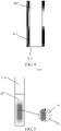
FIG. 5 is a schematic structural diagram of a cigarette used in combination with the cigarette device inFIG. 1 . - To better describe and illustrate embodiments and/or examples disclosed herein, reference may be made to one or more accompanying drawings. Additional details or examples used to describe the accompanying drawings should not be considered as limiting the scope of any of the disclosed application, currently described embodiments and/or examples, and the best modes of the applications currently understood.
- To help understand this application, the following describes this application more fully with reference to the related accompanying drawings. Exemplary embodiments of this application are provided in the accompanying drawings. However, this application may be implemented in many different forms, and is not limited to the embodiments described in this specification. On the contrary, the embodiments are provided to make understanding of the disclosed content of this application more comprehensive.
- It should be noted that, when an element is referred to as "being fixed to" another element, the element may be directly on the another element, or an intermediate element may be present. When an element is considered to be "connected to" another element, the element may be directly connected to the another element, or an intermediate element may also be present. The terms "vertical", "horizontal", "left", and "right" and similar expressions used in this specification are merely used for the purpose of description, and "outer" and "inner" are relative to a profile of a structure.
- Unless otherwise defined, meanings of all technical and scientific terms used in this specification are the same as those usually understood by a person skilled in the art to which this application belongs. In this application, terms used in the specification of this application are merely intended to describe objectives of the specific embodiments, but are not intended to limit this application.
- Referring to
FIG. 1 , acigarette device 200 is provided according to an implementation. Thecigarette device 200 includes ahousing 201. Aloading cavity 203, apower supply 205, anairflow sensing apparatus 208, and acircuit control unit 209 are disposed in thehousing 201. - The
housing 201 is provided with acigarette insertion opening 202, and theloading cavity 203 is disposed in thehousing 201 and connected to thecigarette insertion opening 202. Theloading cavity 203 is configured to load acigarette 100, and aloading chamber 207 of theloading cavity 203 is in communication with thecigarette insertion opening 202. - An electromagnetic
induction heating element 204 surrounds the outside of theloading cavity 203, and the electromagneticinduction heating element 204 is electrically connected to thepower supply 205. Thecigarette device 200 may be used in combination with acigarette 100 including a magnetic material. In such a cigarette, the magnetic material is uniformly distributed in tobacco and in direct contact with the tobacco. In this way, in a working state of thecigarette device 200, the electromagneticinduction heating element 204 generates a high-frequency magnetic field; the magnetic materials in the cigarette generate heat quickly under magnetic induction eddy current and magnetic hysteresis, and transmits the heat to the tobacco quickly, so that the preheating time of the cigarette is reduced, thereby achieving quick cigarette lighting for vaping. In addition, the entire cigarette is approximately heated at the same time, achieving higher utilization of the tobacco, and a burnt taste due to charred tobacco is avoided, thereby obtaining a relatively good taste. The electromagneticinduction heating element 204 may be an electromagnetic induction coil and surrounds the outside of theloading cavity 203 in a winding manner. - After the
cigarette 100 is loaded into theloading cavity 203, the cigarette is in close contact with a cavity wall of theloading cavity 203. Afluid channel 216 is formed between theloading cavity 203 and thehousing 201, and thefluid channel 216 is in communication with the outside of thehousing 201 and theloading chamber 207 of theloading cavity 203, respectively. Thecircuit control unit 209 is electrically connected to the electromagneticinduction heating element 204 and theairflow sensing apparatus 208, respectively. Theairflow sensing apparatus 208 is disposed in thefluid channel 216 to sense an airflow speed in thefluid channel 216, and thecircuit control unit 209 controls, according to the airflow speed sensed by theairflow sensing apparatus 208, the electromagneticinduction heating element 204 to work or stop. In this way, when thecigarette 100 is vaped by using thecigarette device 200, air may enter thehousing 201 and enter theloading cavity 203 through thefluid channel 216; theairflow sensing apparatus 208 senses airflow changes and feeds back an electrical signal to thecircuit control unit 209; thecircuit control unit 209 controls the electromagneticinduction heating element 204 to apply a high-frequency alternating electric field to generate a high-frequency alternating magnetic field in theloading cavity 203, and thus the magnetic material in the cigarette generates heat quickly under the action of electromagnetic induction to bake the cigarette. After the vaping is stopped, theairflow sensing apparatus 208 may sense that the airflow stops and feed back an electrical signal to thecircuit control unit 209; thecircuit control unit 209 controls the electromagneticinduction heating element 204 to stop applying the high-frequency alternating electric field, and heating is stopped immediately. Therefore, thecigarette device 200 allows for immediate vaping and immediate stopping. It is unnecessary to vape the whole cigarette at one time. When the vaping is resumed from an interruption, the cigarette is still baked uniformly and quickly according to the foregoing process, and no abnormal taste is generated. - To prevent the magnetic material in the cigarette from being interfered, a material for manufacturing the
loading cavity 203 needs to have a non-magnetic shielding property, for example, paramagnetism or diamagnetism. Further, theloading cavity 203 is made of a heat sink material with a thermal conductivity not lower than 20 W/m·K. The material has good thermal conduction performance, and a temperature thereof may not rise significantly with a high temperature of the cigarette during vaping, which helps the cigarette cool to a low temperature quickly after the vaping is stopped, thereby further achieving immediate vaping and immediate stopping and ensuring a good taste when the vaping process is resumed from interruption. Specifically, theloading cavity 203 may be made of a ceramic material such as aluminum oxide or aluminum nitride with a thermal conductivity not lower than 20 W/m·K. - Further, the
housing 201 may be provided with a first air hole 206 in communication with thefluid channel 216, to achieve communication between thefluid channel 216 and the outside of thehousing 201. That is, the air may enter thefluid channel 216 through the first air hole 206. There may be one or more first air holes 206. In an embodiment, as shown inFIG. 1 , at least onefirst air hole 206a is provided at an upper part of thehousing 201. In this case, thefirst air hole 206a may be an annular through hole surrounding thecigarette insertion opening 202 as shown inFIG. 2 ; or as shown inFIG. 3 , a plurality offirst air holes 206a are arranged on an outer side of thecigarette insertion opening 202 at uniform intervals. - The
loading cavity 203 may be provided with asecond air hole 217 in communication with thefluid channel 216, to achieve communication between thefluid channel 216 and theloading chamber 207. There may be one or more second air holes 217. Thesecond air hole 217 may be provided at a side wall and/or a bottom wall of theloading cavity 203. In an embodiment, thesecond air hole 217 is provided at the bottom wall of theloading cavity 203. In this case, a plurality ofsecond air holes 217 may be disposed uniformly as shown inFIG. 1 . Alternatively, onesecond air hole 217 may be disposed, and a hole diameter of thesecond air hole 217 is equal to an inner diameter of theloading cavity 203. That is, in this embodiment, the bottom wall of theloading cavity 203 is fully opened, as shown inFIG. 4 . In addition, when thesecond air hole 217 is provided at the bottom wall of theloading cavity 203, at least onefirst air hole 206b may be further provided at a lower part of thehousing 201, and thefirst air hole 206b is located below theloading cavity 203, so that a part of air enters thehousing 201 through thefirst air hole 206b and further enters theloading chamber 207 through thesecond air hole 217 at the bottom wall of theloading cavity 203 during usage. This part of air helps further adjust an airflow amount and resistance against vaping, thereby providing a better vaping experience. - The
airflow sensing apparatus 208 may be disposed at any position that helps sense the airflow, in thehousing 201, for example, disposed near the first air hole 206 or disposed near thesecond air hole 217. - To improve the stability of the
loading cavity 203 in thehousing 201, asupport element 210 configured to support theloading cavity 203 may be further disposed, and theloading cavity 203 is connected to an inner wall of thehousing 201 through thesupport element 210. In an embodiment, thesupport element 210 may be disposed at a bottom of theloading cavity 203 and is an annular element, to achieve good support and fixing functions. In this case, if thefirst air hole 206a is provided only at the outer side of thecigarette insertion opening 202 and thesecond air hole 217 is provided at the bottom wall of theloading cavity 203, thesupport element 210 needs to be provided with athird air hole 218 in communication with thefluid channel 216, to allow the air entering thehousing 201 from thefirst air hole 206a to enter theloading chamber 207 through thethird air hole 218 and thesecond air hole 217 sequentially. Thesupport element 210 may be manufactured integrally with thehousing 201, or may be a separate element. - In this way, during usage, an airflow channel shown by arrows in
FIG. 1 may be formed in thecigarette device 200. External air enters thehousing 201 from thefirst air hole 206a on the outer side of thecigarette insertion opening 202, moves downward, and then moves upward to enter theloading chamber 207 through thethird air hole 218 of thesupport element 210 and thesecond air hole 217 at the bottom wall of theloading cavity 203. A part of heat generated by the electromagneticinduction heating element 204 during working can be taken away by airflow, to cool down the electromagneticinduction heating element 204 and an outer side wall of theloading cavity 203, reduce heat transmitted to thehousing 201, and prevent the temperature of the cigarette device from being excessively high when being held. In addition, heated air entering the cigarette also improves utilization of energy. - The
cigarette device 200 may further include conventional components in this field, such as aswitch 212, adisplay screen 213, acontrol button 214, a charginginterface 215 and the like, and these components may be disposed on thehousing 201. - The following briefly describes a
cigarette 100 that can be vaped by using the foregoingcigarette device 200 according to an implementation. Referring toFIG. 5 , thecigarette 100 includes acigarette body 110 and afilter 120. Thecigarette body 110 is connected to thefilter 120. Thefilter 120 includes a function of condensing and filtering vapor. - The
cigarette body 110 includestobacco 111 and amagnetic material 112 uniformly distributed in thetobacco 111. Themagnetic material 112 is used for heating thetobacco 111 under the action of electromagnetic induction. That is, under the action of electromagnetic induction, a temperature of themagnetic material 112 rises, and thus heat is transmitted to thetobacco 111 to bake thetobacco 111. Since themagnetic material 112 is uniformly distributed in thetobacco 111, under the action of electromagnetic induction, themagnetic materials 112 form uniform heating points in thecigarette body 110, so that thetobacco 111 is uniformly heated, achieving higher taste consistency, and thetobacco 111 will not be partially charred, thereby avoiding a burnt taste and achieving higher tobacco utilization efficiency. In addition, the addition of themagnetic material 112 causes the heat to be transmitted fast in thetobacco 111, thereby effectively shortening the preheating time and generating vapor quickly. - To achieve a good induction heating effect, a ratio of a volume of the
magnetic material 112 to a total volume of thecigarette body 110 is in a range from 1% to 30%. In an embodiment, the ratio of the volume of themagnetic materials 112 to the total volume of thecigarette body 110 is in a range from 3% to 10%. - The
magnetic material 112 is in the shape of particles, and a particle size thereof may be in a range from 10 µm to 200 µm. In an embodiment, the particle size of themagnetic material 112 is in a range from 50 µm to 150 µm. Themagnetic material 112 within the foregoing particle size range can achieve a good induction heating effect and can be easily incorporated into thetobacco 111 more uniformly. - The
magnetic material 112 may be various conventional materials generating heat under the action of electromagnetic induction. Specifically, themagnetic material 112 may be ferromagnetic metal powder, such as Fe powder, Co powder, Ni powder, silicon steel powder, permalloy powder, or Al-Ni-Co powder. In an embodiment, themagnetic material 112 is Fe powder or Ni powder, which has high magnetic conductivity and electrical resistivity and can be heated quickly, and also has high thermal conductivity, thereby achieving high heating uniformity for the cigarette. - The
magnetic material 112 may be added into thetobacco 111 in a preparation process of thecigarette 100, to be uniformly distributed in thetobacco 111. For example, thetobacco 111 and themagnetic material 112 may be mixed uniformly in advance, and then thecigarette body 110 is obtained through shaping by means of coating, die-casting, thermoforming or the like. - When the
cigarette 100 is used in combination with thecigarette device 200, the cigarette can be heated uniformly and generate vapor quickly, to ensure a consistent vaping taste and improve the utilization of the tobacco while achieving immediate vaping and immediate stopping, which helps improve user experience. - In some specific examples, the
cigarette 100 may be used as a part of thecigarette device 200, that is, thecigarette device 200 may include thecigarette 100. - This application is further described below by using an embodiment, but the embodiment is not intended to limit this application.
- A structure of a cigarette device of this embodiment is shown in
FIG. 1 . Thecigarette device 200 includes ahousing 201. Thehousing 201 is provided with acigarette insertion opening 202. Aloading cavity 203 is connected to thecigarette insertion opening 202. Afirst air hole 206a is provided at an outer side of thecigarette insertion opening 202. A lower part of thehousing 201 is located below a lower part of theloading cavity 203 and is provided with afirst air hole 206b, and a bottom wall of theloading cavity 203 is provided with asecond air hole 217. Theloading cavity 203 is connected to thehousing 201 through anannular support element 210 that is connected to a bottom of thehousing 201, and thesupport element 210 is provided with athird air hole 218. An electromagneticinduction heating element 204 surrounds the outside of theloading cavity 203, the electromagneticinduction heating element 204 is electrically connected to apower supply 205 and acircuit control unit 209, and thecircuit control unit 209 is electrically connected to anairflow sensing apparatus 208. Thehousing 201 is further provided with aswitch 212, adisplay screen 213, acontrol button 214, and a charginginterface 215. Theloading cavity 203 is made of an alumina ceramic, with a thermal conductivity of 25 W/m·K. - Tobacco and Fe powder (with a particle size of 100 µm) used as a magnetic material were mixed uniformly and shaped as a cigarette body, where a volume proportion of the Fe powder was 10%. The cigarette body was then connected to a filter, to obtain a cigarette with the structure shown in
FIG. 5 . - The cigarette was placed into the
loading cavity 203 of the cigarette device of this embodiment for vaping tests. Test results are as follows. Quick vapor generation, good vapor consistency, a pure taste, and no foreign taste are realized. Immediate vaping and immediate stopping are allowed. In addition, after the vaping is stopped, the cigarette can be cooled down to 150°C or below within 1 second, and a good taste can be still obtained when the cigarette is vaped again. - A cigarette device of this embodiment is a low-temperature baking cigarette device available on the market, and a heating element thereof is a sheet-like internal heating plate.
- The conventional low-temperature baking cigarette was placed into the cigarette device of this embodiment for vaping tests. Test results are as follows: slow vapor generation, poor vapor taste consistency, and presence of a foreign taste. Moreover, after the vaping is stopped, the temperature of the cigarette decreases slowly and is still in a baked state, that is, once the cigarette device is started, immediate vaping and immediate stopping are not allowed, and an abnormal taste may be generated when the baking of the cigarette is resumed from interruption.
- The technical features in the foregoing embodiments may be randomly combined. For concise description, not all possible combinations of the technical features in the embodiments are described. However, provided that combinations of the technical features do not conflict with each other, the combinations of the technical features are considered as falling within the scope described in this specification.
- The foregoing embodiments merely express several implementations of this application. The descriptions thereof are relatively specific and detailed, but should not be understood as limitations to the scope of this application. It should be noted that for a person of ordinary skill in the art, several variants and improvements can be made without departing from the idea of this application. These variants and improvements belong to the protection scope of this application. Therefore, the protection scope of the patent of this application shall be subject to the appended claims.
Claims (16)
- A cigarette device, characterized by, comprisinga housing;a loading cavity, disposed in the housing and configured to load a cigarette;a fluid channel, located between the loading cavity and the housing, the fluid channel being in communication with an outside of the housing and a loading chamber of the loading cavity;an airflow sensing apparatus, disposed in the housing, the airflow sensing apparatus being disposed in the fluid channel to sense an airflow speed in the fluid channel;a power supply, disposed in the housing;an electromagnetic induction heating element, surrounding an outside of the loading cavity, the electromagnetic induction heating element being electrically connected to the power supply; anda circuit control unit, disposed in the housing, the circuit control unit being electrically connected to the airflow sensing apparatus and the electromagnetic induction heating element, and controlling, according to the airflow speed sensed by the airflow sensing apparatus, the electromagnetic induction heating element to work or stop.
- The cigarette device according to claim 1, wherein the loading cavity is made of a heat sink material with a thermal conductivity not lower than 20 W/m·K and a non-magnetic shielding property.
- The cigarette device according to claim 2, wherein the loading cavity is made of a ceramic material with a thermal conductivity not lower than 20 W/m K.
- The cigarette device according to claim 1, wherein the housing is provided with a cigarette insertion opening, the loading cavity is connected to the cigarette insertion opening, and the loading chamber of the loading cavity is in communication with the cigarette insertion opening.
- The cigarette device according to claim 4, wherein the housing is provided with a first air hole in communication with the fluid channel.
- The cigarette device according to claim 5, wherein there are one or more first air holes, and at least one of the first air holes is provided at an upper part of the housing.
- The cigarette device according to claim 6, wherein the first air holes are annular through holes surrounding the cigarette insertion opening.
- The cigarette device according to claim 6, wherein there are a plurality of first air holes, and the plurality of first air holes are arranged on an outer side of the cigarette insertion opening at uniform intervals.
- The cigarette device according to claim 6, wherein there are a plurality of first air holes, and at least one of the first air holes is provided at a lower part of the housing and located below the loading cavity.
- The cigarette device according to claim 4, wherein the loading cavity is provided with a second air hole in communication with the fluid channel.
- The cigarette device according to claim 10, wherein the second air hole is provided at a bottom wall of the loading cavity.
- The cigarette device according to claim 11, wherein there are a plurality of second air holes, and the plurality of second air holes are uniformly provided at the bottom wall of the loading cavity.
- The cigarette device according to claim 11, wherein there is one second air hole, and a hole diameter of the second air hole is equal to an inner diameter of the loading cavity.
- The cigarette device according to any one of claims 1 to 13, further comprising a support element, the loading cavity being connected to an inner wall of the housing through the support element.
- The cigarette device according to claim 14, wherein the support element is disposed at a bottom of the loading cavity, and the support element is an annular element.
- The cigarette device according to claim 15, wherein the support element is provided with a third air hole in communication with the fluid channel.
Applications Claiming Priority (2)
| Application Number | Priority Date | Filing Date | Title |
|---|---|---|---|
| CN201910884667.5A CN112535321A (en) | 2019-09-19 | 2019-09-19 | Smoking set |
| PCT/CN2020/114371 WO2021052233A1 (en) | 2019-09-19 | 2020-09-10 | Electronic cigarette device |
Publications (2)
| Publication Number | Publication Date |
|---|---|
| EP4032418A1 true EP4032418A1 (en) | 2022-07-27 |
| EP4032418A4 EP4032418A4 (en) | 2023-10-25 |
Family
ID=74884500
Family Applications (1)
| Application Number | Title | Priority Date | Filing Date |
|---|---|---|---|
| EP20865622.3A Pending EP4032418A4 (en) | 2019-09-19 | 2020-09-10 | ELECTRONIC CIGARETTE DEVICE |
Country Status (4)
| Country | Link |
|---|---|
| US (1) | US12127596B2 (en) |
| EP (1) | EP4032418A4 (en) |
| CN (1) | CN112535321A (en) |
| WO (1) | WO2021052233A1 (en) |
Cited By (1)
| Publication number | Priority date | Publication date | Assignee | Title |
|---|---|---|---|---|
| US12520880B2 (en) | 2021-01-18 | 2026-01-13 | Altria Client Services Llc | Heat-not-burn (HNB) aerosol-generating devices including energy based heater control, and methods of controlling a heater |
Families Citing this family (8)
| Publication number | Priority date | Publication date | Assignee | Title |
|---|---|---|---|---|
| CN113156050B (en) * | 2021-05-12 | 2024-08-16 | 中国烟草总公司郑州烟草研究院 | A system and method for evaluating cigar rolling uniformity |
| CN113841937B (en) * | 2021-09-13 | 2024-11-26 | 深圳市太美亚电子科技有限公司 | An electronic cigarette based on electromagnetic temperature control technology and control method thereof |
| CN113892695A (en) * | 2021-11-09 | 2022-01-07 | 深圳麦克韦尔科技有限公司 | Heating device and electronic atomization device |
| GB202118879D0 (en) * | 2021-12-23 | 2022-02-09 | Nicoventures Trading Ltd | Aerosol provision device |
| WO2023240511A1 (en) * | 2022-06-15 | 2023-12-21 | 海南摩尔兄弟科技有限公司 | Electronic atomization device, and atomizer |
| CN115670027A (en) * | 2022-10-13 | 2023-02-03 | 深圳市拓普联科技术股份有限公司 | HNB (home node B) electronic cigarette heater and cigarette |
| CN116369589A (en) * | 2023-05-18 | 2023-07-04 | 湖北中烟工业有限责任公司 | An air heating component with adjustable air velocity and its application |
| CN116602461A (en) * | 2023-06-26 | 2023-08-18 | 湖北中烟工业有限责任公司 | Heating smoking set and temperature control method |
Family Cites Families (29)
| Publication number | Priority date | Publication date | Assignee | Title |
|---|---|---|---|---|
| US6040560A (en) * | 1996-10-22 | 2000-03-21 | Philip Morris Incorporated | Power controller and method of operating an electrical smoking system |
| CN101940369A (en) * | 2009-07-09 | 2011-01-12 | 宁波博迪电子科技有限公司 | Smoking-type electronic fragrant mist device and manufacturing method thereof |
| US9423152B2 (en) * | 2013-03-15 | 2016-08-23 | R. J. Reynolds Tobacco Company | Heating control arrangement for an electronic smoking article and associated system and method |
| US10279934B2 (en) * | 2013-03-15 | 2019-05-07 | Juul Labs, Inc. | Fillable vaporizer cartridge and method of filling |
| CN103190705B (en) | 2013-04-01 | 2015-05-20 | 上海烟草集团有限责任公司 | Tobacco for heating non-combustion apparatus and preparation method thereof |
| CN103932401B (en) * | 2013-09-29 | 2015-09-30 | 深圳麦克韦尔股份有限公司 | Electronic cigarette |
| CN103750566B (en) * | 2013-12-13 | 2016-03-30 | 浙江中烟工业有限责任公司 | A kind of non-burning smoking apparatus based on electromagnetic wave heating |
| CN103783668A (en) * | 2013-12-13 | 2014-05-14 | 浙江中烟工业有限责任公司 | Electromagnetic wave heating device for non-burning cigarettes |
| CN103734910A (en) * | 2013-12-13 | 2014-04-23 | 浙江中烟工业有限责任公司 | Non-combustion-cigarette graphite heating device |
| US10159282B2 (en) * | 2013-12-23 | 2018-12-25 | Juul Labs, Inc. | Cartridge for use with a vaporizer device |
| CN204273231U (en) * | 2014-04-24 | 2015-04-22 | 惠州市吉瑞科技有限公司 | A kind of electronic cigarette |
| CN104013110A (en) * | 2014-06-11 | 2014-09-03 | 湖南中烟工业有限责任公司 | Baking-type atomizer and electronic cigarette with same |
| CN104095295A (en) * | 2014-07-18 | 2014-10-15 | 云南中烟工业有限责任公司 | Smoking set with function of electromagnetic induction heating |
| CN104824851A (en) * | 2015-04-10 | 2015-08-12 | 矽翔微机电系统(上海)有限公司 | Electronic atomizer, atomization control method and physical sign data monitoring system |
| GB201511361D0 (en) * | 2015-06-29 | 2015-08-12 | Nicoventures Holdings Ltd | Electronic vapour provision system |
| EP3410876B1 (en) * | 2016-02-01 | 2020-04-01 | Philip Morris Products S.a.s. | Aerosol-generating device having multiple power supplies |
| MX388616B (en) * | 2016-02-11 | 2025-03-20 | Juul Labs Inc | SECURE FITTING CARTRIDGES FOR VAPORIZING DEVICES |
| WO2017207582A1 (en) * | 2016-05-31 | 2017-12-07 | Philip Morris Products S.A. | Refillable aerosol-generating article |
| CN206079037U (en) * | 2016-09-27 | 2017-04-12 | 陈新文 | Electron cigarette dry combustion method atomizer |
| CN109259310B (en) * | 2017-07-17 | 2024-06-14 | 湖南中烟工业有限责任公司 | Low-temperature smoking device with suspended heating components and smoke extraction system |
| CN207613192U (en) * | 2017-08-03 | 2018-07-17 | 惠州市吉瑞科技有限公司深圳分公司 | A kind of electronic cigarette |
| WO2019030364A1 (en) * | 2017-08-09 | 2019-02-14 | Philip Morris Products S.A. | Aerosol-generating device having an elastic susceptor |
| KR102138245B1 (en) * | 2017-10-30 | 2020-07-28 | 주식회사 케이티앤지 | Aerosol generating apparatus |
| US11272741B2 (en) * | 2018-01-03 | 2022-03-15 | Cqens Technologies Inc. | Heat-not-burn device and method |
| CN208144423U (en) * | 2018-02-26 | 2018-11-27 | 常州市派腾电子技术服务有限公司 | Flue-cured tobacco heating member, pipe bowl device and electronic cigarette |
| CN109247619A (en) * | 2018-05-28 | 2019-01-22 | 宁波安百利印刷有限公司 | A kind of method for heating and controlling and smoking set of electronic cigarette cigarette |
| CN108634380A (en) * | 2018-07-23 | 2018-10-12 | 重庆中烟工业有限责任公司 | Low-temperature bake smoking set |
| KR200491034Y1 (en) * | 2019-04-08 | 2020-02-10 | 최서정 | Cigarette smoke ventilator |
| CN211510581U (en) * | 2019-09-19 | 2020-09-18 | 深圳麦克韦尔科技有限公司 | Smoking set |
-
2019
- 2019-09-19 CN CN201910884667.5A patent/CN112535321A/en active Pending
-
2020
- 2020-09-10 EP EP20865622.3A patent/EP4032418A4/en active Pending
- 2020-09-10 WO PCT/CN2020/114371 patent/WO2021052233A1/en not_active Ceased
-
2022
- 2022-03-14 US US17/694,123 patent/US12127596B2/en active Active
Cited By (1)
| Publication number | Priority date | Publication date | Assignee | Title |
|---|---|---|---|---|
| US12520880B2 (en) | 2021-01-18 | 2026-01-13 | Altria Client Services Llc | Heat-not-burn (HNB) aerosol-generating devices including energy based heater control, and methods of controlling a heater |
Also Published As
| Publication number | Publication date |
|---|---|
| US12127596B2 (en) | 2024-10-29 |
| US20220232895A1 (en) | 2022-07-28 |
| EP4032418A4 (en) | 2023-10-25 |
| CN112535321A (en) | 2021-03-23 |
| WO2021052233A1 (en) | 2021-03-25 |
Similar Documents
| Publication | Publication Date | Title |
|---|---|---|
| US12127596B2 (en) | Cigarette device | |
| CN211510581U (en) | Smoking set | |
| US20220338547A1 (en) | Aerosol generation apparatus and aerosol generation substrate | |
| CN205624467U (en) | Tobacco tar heating element reaches electron cigarette and atomizer including this tobacco tar heating element | |
| JP2016528874A (en) | Induction heating apparatus and system for aerosol generation | |
| TW201544171A (en) | Aerosol-forming substrate and aerosol-delivery system | |
| CN108634378B (en) | Low-temperature baking smoking set based on magnetic material | |
| EP4309521B1 (en) | Electromagnetic heater for heating a hookah and electromagnetic heating device for a hookah | |
| CN108669654B (en) | A low-temperature heating smoking device | |
| EP4566469A1 (en) | Heating assembly, atomizer and aerosol generating apparatus | |
| JP7709229B2 (en) | Atomization module for use in electromagnetic heating devices | |
| CN212014450U (en) | Aerosol-generating device and aerosol-generating substrate therefor | |
| CN114209090A (en) | Atomizing heating assembly and atomizing heating device thereof | |
| JP7646250B2 (en) | Atomization heating module and atomization heating device | |
| CN108634380A (en) | Low-temperature bake smoking set | |
| CN106344398A (en) | Innovative fire needle instrument for treating aches, pains and multiple difficult miscellaneous diseases | |
| CN115119977A (en) | Electronic atomization device and its heating assembly | |
| WO2022176126A1 (en) | Inhalation device, program, and system | |
| CN108634376A (en) | A kind of low-temperature bake smoking set of full magnetic heating | |
| CN108634373B (en) | Low temperature baking smoker | |
| CN220274905U (en) | Heating components and aerosol generating devices | |
| CN218104903U (en) | A compound induction heating heating element and smoking set | |
| CN217826738U (en) | Heater and aerosol generating device | |
| JP2023020969A (en) | Gas communication module and aerosol generator | |
| JP2023021007A (en) | Atomization main body and aerosol generator |
Legal Events
| Date | Code | Title | Description |
|---|---|---|---|
| STAA | Information on the status of an ep patent application or granted ep patent |
Free format text: STATUS: THE INTERNATIONAL PUBLICATION HAS BEEN MADE |
|
| PUAI | Public reference made under article 153(3) epc to a published international application that has entered the european phase |
Free format text: ORIGINAL CODE: 0009012 |
|
| STAA | Information on the status of an ep patent application or granted ep patent |
Free format text: STATUS: REQUEST FOR EXAMINATION WAS MADE |
|
| 17P | Request for examination filed |
Effective date: 20220330 |
|
| AK | Designated contracting states |
Kind code of ref document: A1 Designated state(s): AL AT BE BG CH CY CZ DE DK EE ES FI FR GB GR HR HU IE IS IT LI LT LU LV MC MK MT NL NO PL PT RO RS SE SI SK SM TR |
|
| DAV | Request for validation of the european patent (deleted) | ||
| DAX | Request for extension of the european patent (deleted) | ||
| A4 | Supplementary search report drawn up and despatched |
Effective date: 20230921 |
|
| RIC1 | Information provided on ipc code assigned before grant |
Ipc: A24F 40/465 20200101ALI20230915BHEP Ipc: A24F 40/485 20200101ALI20230915BHEP Ipc: A24F 40/53 20200101ALI20230915BHEP Ipc: A24F 13/00 20060101AFI20230915BHEP |
|
| RAP3 | Party data changed (applicant data changed or rights of an application transferred) |
Owner name: SHENZHEN SMOORE TECHNOLOGY LIMITED |
|
| RAP3 | Party data changed (applicant data changed or rights of an application transferred) |
Owner name: SHENZHEN SMOORE TECHNOLOGY LIMITED |
|
| STAA | Information on the status of an ep patent application or granted ep patent |
Free format text: STATUS: EXAMINATION IS IN PROGRESS |
|
| 17Q | First examination report despatched |
Effective date: 20251205 |