EP4032385A1 - Electrical surge protection for an outdoor robotic work tool system - Google Patents
Electrical surge protection for an outdoor robotic work tool system Download PDFInfo
- Publication number
- EP4032385A1 EP4032385A1 EP22152149.5A EP22152149A EP4032385A1 EP 4032385 A1 EP4032385 A1 EP 4032385A1 EP 22152149 A EP22152149 A EP 22152149A EP 4032385 A1 EP4032385 A1 EP 4032385A1
- Authority
- EP
- European Patent Office
- Prior art keywords
- work tool
- robotic work
- charging station
- activation
- charging
- Prior art date
- Legal status (The legal status is an assumption and is not a legal conclusion. Google has not performed a legal analysis and makes no representation as to the accuracy of the status listed.)
- Granted
Links
- 230000004224 protection Effects 0.000 title description 11
- 230000004913 activation Effects 0.000 claims abstract description 113
- 230000033001 locomotion Effects 0.000 claims abstract description 53
- 238000000034 method Methods 0.000 claims abstract description 33
- 230000005540 biological transmission Effects 0.000 claims description 21
- 239000004020 conductor Substances 0.000 claims description 6
- 230000007613 environmental effect Effects 0.000 claims description 6
- 238000000926 separation method Methods 0.000 claims description 2
- 230000003993 interaction Effects 0.000 description 5
- 244000025254 Cannabis sativa Species 0.000 description 4
- 238000004891 communication Methods 0.000 description 4
- 238000004590 computer program Methods 0.000 description 4
- 238000001514 detection method Methods 0.000 description 4
- 238000002955 isolation Methods 0.000 description 3
- 238000013459 approach Methods 0.000 description 2
- 238000003032 molecular docking Methods 0.000 description 2
- 241000196324 Embryophyta Species 0.000 description 1
- 229920003266 Leaf® Polymers 0.000 description 1
- 241001494496 Leersia Species 0.000 description 1
- 241001417527 Pempheridae Species 0.000 description 1
- 230000008859 change Effects 0.000 description 1
- 238000002485 combustion reaction Methods 0.000 description 1
- 230000001419 dependent effect Effects 0.000 description 1
- 238000013461 design Methods 0.000 description 1
- 238000009313 farming Methods 0.000 description 1
- 230000001939 inductive effect Effects 0.000 description 1
- 230000004807 localization Effects 0.000 description 1
- 238000012423 maintenance Methods 0.000 description 1
- 238000013507 mapping Methods 0.000 description 1
- 239000003550 marker Substances 0.000 description 1
- 239000002184 metal Substances 0.000 description 1
- 230000007935 neutral effect Effects 0.000 description 1
- 230000008569 process Effects 0.000 description 1
- 238000012545 processing Methods 0.000 description 1
- 230000011664 signaling Effects 0.000 description 1
- 238000012546 transfer Methods 0.000 description 1
- 230000000007 visual effect Effects 0.000 description 1
Images


Classifications
-
- H—ELECTRICITY
- H02—GENERATION; CONVERSION OR DISTRIBUTION OF ELECTRIC POWER
- H02H—EMERGENCY PROTECTIVE CIRCUIT ARRANGEMENTS
- H02H1/00—Details of emergency protective circuit arrangements
- H02H1/04—Arrangements for preventing response to transient abnormal conditions, e.g. to lightning or to short duration over voltage or oscillations; Damping the influence of dc component by short circuits in ac networks
-
- A—HUMAN NECESSITIES
- A01—AGRICULTURE; FORESTRY; ANIMAL HUSBANDRY; HUNTING; TRAPPING; FISHING
- A01D—HARVESTING; MOWING
- A01D34/00—Mowers; Mowing apparatus of harvesters
- A01D34/006—Control or measuring arrangements
- A01D34/008—Control or measuring arrangements for automated or remotely controlled operation
-
- B—PERFORMING OPERATIONS; TRANSPORTING
- B60—VEHICLES IN GENERAL
- B60L—PROPULSION OF ELECTRICALLY-PROPELLED VEHICLES; SUPPLYING ELECTRIC POWER FOR AUXILIARY EQUIPMENT OF ELECTRICALLY-PROPELLED VEHICLES; ELECTRODYNAMIC BRAKE SYSTEMS FOR VEHICLES IN GENERAL; MAGNETIC SUSPENSION OR LEVITATION FOR VEHICLES; MONITORING OPERATING VARIABLES OF ELECTRICALLY-PROPELLED VEHICLES; ELECTRIC SAFETY DEVICES FOR ELECTRICALLY-PROPELLED VEHICLES
- B60L53/00—Methods of charging batteries, specially adapted for electric vehicles; Charging stations or on-board charging equipment therefor; Exchange of energy storage elements in electric vehicles
- B60L53/60—Monitoring or controlling charging stations
-
- H—ELECTRICITY
- H02—GENERATION; CONVERSION OR DISTRIBUTION OF ELECTRIC POWER
- H02H—EMERGENCY PROTECTIVE CIRCUIT ARRANGEMENTS
- H02H3/00—Emergency protective circuit arrangements for automatic disconnection directly responsive to an undesired change from normal electric working condition with or without subsequent reconnection ; integrated protection
- H02H3/02—Details
- H02H3/021—Details concerning the disconnection itself, e.g. at a particular instant, particularly at zero value of current, disconnection in a predetermined order
Definitions
- the present disclosure relates to outdoor robotic work tool system with an outdoor robotic work tool and a work tool charging station, and in particular high voltage electrical surge protections for the outdoor robotic work tool and the work tool charging station with associated electrical components, especially electrical surges which are due to one or more lightning strikes during a thunder storm.
- the outdoor robotic work tool can for example be constituted by a robotic lawn mower.
- Automated or robotic power tools such as robotic lawn mowers are becoming increasingly more popular.
- a work area such as a garden
- the work area can be enclosed by a boundary wire with the purpose of keeping the robotic lawn mower inside the work area.
- An electric control signal may be transmitted through the boundary wire thereby generating an (electro-) magnetic field emanating from the boundary wire.
- the robotic lawn mower is typically arranged with one or more sensors adapted to sense the control signal.
- Other types of navigation systems can be used instead of, or in combination with a boundary wire.
- Such navigation systems can for example be based on satellite navigation systems and/or local radio beacons or image processing such as Visual Simultaneous Localization and Mapping (VSLAM).
- VSLAM Visual Simultaneous Localization and Mapping
- the robotic lawn mower can then cut grass on a user's lawn automatically and can be charged automatically without intervention of the user, and no longer needs to be manually managed after being set once.
- the robotic lawn mower typically comprises charging skids for contacting corresponding contact plates in a charging station when docking into the charging station for receiving a charging current through, and possibly also for transferring information by means of electrical communication between the charging station and the robotic lawn mower.
- a lightning strike may damage robotic lawn mower equipment such as the robotic lawn mower itself, especially during charging, power supply units, loop generators and other lawn mower system electronics. This is due to high voltage electrical surges, inflicted from lightning strikes, entering the robotic lawn mower equipment via the electrical mains and/or the boundary wire if used.
- the document SE 539127 discloses a surge arrester for a robotic lawn mower assembly, comprising a grounding rod and protection circuitry adapted to lead high voltage electrical surges via the grounding rod. A more reliable and efficient high voltage electrical surge protection arrangement is desired.
- the object of the present disclosure is to provide an outdoor robotic work tool system, such as a robotic lawn mower system, comprising an improved high voltage electrical surge protection arrangement.
- a robotic work tool system comprising controlling the movement of an outdoor robotic work tool and controlling the outdoor robotic work tool to move an activation member at an outdoor robotic work tool charging station used for charging at least one rechargeable electric power source of the outdoor robotic work tool.
- the movement is made in an activation direction such that an electrical switch arrangement is activated and a protect mode is entered, wherein, upon activation, the electrical switch arrangement is used for isolating at least one electric unit from at least one electrical connection. Upon de-activation, the electrical switch arrangement is used for electrically connecting the electric unit to said electrical connection.
- the outdoor robotic work tool can activate and de-activate a switch arrangement that is adapted to break an electrical connection when activated, such that at least one electric is isolated from at least one electrical connection.
- This enables a possibility to protect electrical components both in the charging station and in the outdoor robotic work tool, where such a protection for example is desired in the case of a thunderstorm condition where electrical surges can occur due to lightning strikes.
- the charging station is adapted for a charging entering movement direction and a protect mode entering movement direction that differs from the charging entering movement direction. Controlling the outdoor robotic work tool to move an activation member comprises controlling the outdoor robotic work tool to enter the charging station in the protect mode entering movement direction.
- controlling the outdoor robotic work tool to enter the charging station in the protect mode entering movement direction comprises controlling the outdoor robotic work tool to be positioned away from the charging station with its back facing the activation member, and controlling the outdoor robotic work tool to move rearwards towards the activation member until the activation member is moved sufficiently to activate the electrical switch arrangement.
- the method comprises determining the possibility of the occurrence of a thunder storm by receiving weather data from a remote server.
- the method comprises determining if the possibility of the occurrence of a thunder storm exceeds a certain threshold, and if that is the case, the method comprises controlling the outdoor robotic work tool to move the activation member in the activation direction.
- the method comprises determining if the possibility of the occurrence of a thunder storm falls below a certain threshold. If that is the case, the method further comprises controlling the outdoor robotic work tool to move away from the charging station such that the activation member is released sufficiently, such that it is moved in a de-activation direction, to de-activate the electrical switch arrangement, and controlling the outdoor robotic work tool to continue its previously discontinued task.
- the present disclosure also relates to outdoor robotic work tool charging stations, outdoor robotic work tools and robotic work tool systems that are associated with the above advantages.
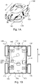
- FIG 1A shows a perspective view of a robotic lawn mower 100
- Figure 1B shows a schematic overview of the robotic lawn mower 100
- the robotic lawn mower 100 is adapted for a forward travelling direction D, has a main body 140 and a plurality of wheels 130; in this example the robotic lawn mower 100 has four wheels 130, two front wheels and two rear wheels.
- the robotic lawn mower 100 comprises a control unit 110 and at least one electric motor 150, where at least some of the wheels 130 are drivably connected to at least one electric motor 150. It should be noted that even if the description herein is focused on electric motors, combustion engines may alternatively be used in combination with an electric motor arrangement.
- the robotic lawn mower 100 may be a multi-chassis type or a mono-chassis type.
- a multi-chassis type comprises two or more body parts that are movable with respect to one another.
- a mono-chassis type comprises only one main body part.
- the robotic lawn mower 100 is of a mono-chassis type, having a main body part 140.
- the main body part 140 substantially houses all components of the robotic lawn mower 100.
- the robotic lawn mower 100 also comprises a grass cutting device 160, such as a rotating blade or a disc 160 with a plurality of separate rotating blades driven by a cutter motor 165.
- the robotic lawn mower 100 also has at least one rechargeable electric power source such as a battery 155 for providing power to the electric motor arrangement 150 and/or the cutter motor 165.
- the battery 155 is arranged to be charged by means of received charging current from a charging station (not shown), received through charging skids 156 or other suitable charging connectors, generally constituted by a charging reception arrangement 156. Inductive charging without galvanic contact, only by means of electric contact, is also conceivable.
- the battery is generally constituted by a rechargeable electric power source 155 that comprises one or more batteries that can be separately arranged or be arranged in an integrated manner to form a combined battery.
- the robotic lawn mower 100 may further comprise at least one navigation sensor arrangement 175 in a previously known manner, for example comprising a satellite navigation sensor in the form of a GPS (Global Positioning System) device or other Global Navigation Satellite System (GNSS) device, according to some aspects for example using Real Time Kinematic (RTK).
- a satellite navigation sensor in the form of a GPS (Global Positioning System) device or other Global Navigation Satellite System (GNSS) device, according to some aspects for example using Real Time Kinematic (RTK).
- GPS Global Positioning System
- GNSS Global Navigation Satellite System
- RTK Real Time Kinematic
- the robotic lawn mower 100 further comprises at least one environment detection device 170.
- radar transceivers 170 are provided and adapted to transmit signals and to receive reflected signals in a previously well-known manner.
- each radar transceiver 170 comprises a corresponding transmitter arrangement and receiver arrangement together with other necessary circuitry in a well-known manner.
- control unit 110 is adapted to control the environment detection device 170 and to control the speed and direction of the robotic lawn mower 100 in dependence of information acquired by means of the of the environment detection device 170 when the robotic lawn mower 100 is moving.
- control unit 110 is adapted to at least partly process input data from at least one environmental detection device 170.
- the charging station 200 comprises a charging transmission arrangement 210 that is adapted to transfer a charging current to the charging reception arrangement 156.
- the charging station 200 comprises an electrical switch arrangement 216.
- the electrical switch arrangement 216 is adapted to isolate at least one electric unit 220, 221, 222, 223, 224 from at least one electrical connection 230, 231, 232, 233, 234 upon activation such that a protect mode is entered, and to electrically connect the electric unit 220, 221, 222, 223, 224 to said electrical connection 230, 231, 232, 233, 234 when de-activated.
- An activation member 215 is adapted to activate the electrical switch arrangement 216 when being moved in an activation direction A1, according to some aspects by being pushed, towards the charging station 200.
- the electrical switch arrangement 216 is adapted to be activated by the robotic lawn mower 100 when the robotic lawn mower 100 moves the activation member 215 sufficiently in the activation direction A1, and to be de-activated when the robotic lawn mower 100 moves or releases the activation member 215 such that it is moved sufficiently in a de-activation direction A2.
- the terms sufficiently relates to an extent that confers a mode change of the electrical switch arrangement 216, such that the electrical switch arrangement 216 switches from one switch state to another switch state.
- the activation member 215 being moved in the activation direction A1 corresponds to the robotic lawn mower 100 entering the charging station 200 in a protect mode entering movement direction D2
- the activation member 215 being moved in the de-activation direction A2 corresponds to the robotic lawn mower 100 leaving the charging station 200, according to some aspects in the opposite direction.
- the robotic lawn mower 100 can activate and de-activate the switch arrangement 216 that is adapted to break an electrical connection when activated, such that electrical components can be protected.
- a protection is for example desired in the case of a thunderstorm condition where electrical surges can occur due to lightning strikes.
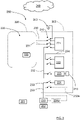
- FIG. 3 that illustrates a robotic work tool system 250 in a schematic manner
- a work area 225 that is enclosed by a boundary wire 220 with the purpose of keeping the robotic lawn mower 100 inside the work area 225.
- An electric control signal may be transmitted through the boundary wire 220 thereby generating a magnetic field emanating from the boundary wire 220.
- the robotic work tool system 250 comprises a boundary wire signal generator 221 that is connected to the boundary wire 220 and is adapted to handle all signaling to and from the boundary wire 220.
- the robotic lawn mower 100 comprises a boundary wire control signal sensor arrangement 228 that is adapted to detect boundary wire signals, where the boundary wire control signal sensor arrangement 228 comprises one or more sensor elements, where there for example can be a plurality of distributed sensor elements.
- Each electric unit as mentioned above can be constituted by one or more different types of units.
- the electric unit can be constituted by one of the boundary wire 220, the boundary wire signal generator 221, a charger control unit 222, a charging unit 223 and a power supply unit 224 that is connected to a mains power outlet 235.
- the boundary wire 220 can be disconnected from the boundary wire signal generator 221, thereby protecting the boundary wire signal generator 221 in case a lightning strike causes an electrical surge in the boundary wire 220.
- One or more of the above electric units can be disconnected and isolated by means of the electrical switch arrangement 216 as described above. If, for example, the power supply unit 224 is not comprised in the charging station 200 but is constituted by a separate external unit that is remote from the charging station 200, the power supply unit 224 may not be possible to isolate from the mains power outlet 235 by means of the electrical switch arrangement 216. This is illustrated by an alternative power supply unit 224a, indicated by dashed lines, where the alternative power supply unit 224a is an external power supply unit 224a that can be an indoor unit or placed remote from the charging station 200 in some other manner, for example connected to an outdoor mains power outlet.
- the robotic work tool system 250 being arranged without a boundary wire and solely depending on a navigation sensor arrangement 175 as described above, there is of course no need to isolate a boundary wire 220 and boundary wire signal generator 221 since these in that case are not comprised in the robotic work tool system 250.
- the robotic work tool system 250 may be arranged for a navigation sensor arrangement 175 together with a relatively small boundary wire at the charging station, only be being used to aid the lawn mower 100 when docking to the charging station 200,
- Which electric units that are adapted to be disconnected and isolated by means of the electrical switch arrangement 216 is thus dependent on which electric units that are comprised in the robotic work tool system 250 and are accessible for the electrical switch arrangement 216, as well as on which electric units that are considered necessary or desired to protect from electrical surges of the kind described above. Practical aspects and cost aspects are also important when determining which electric units that are adapted to be disconnected and isolated by means of the electrical switch arrangement 216.
- the electrical switch arrangement 216 is adapted to provide a mechanical separation S1, S2, constituting an isolation distance, between adjacent electrical conductors C1, C2 of at least 5 cm when activated, and preferably at least 10 cm.
- the electrical switch arrangement 216 is schematically indicated as de-activated, closing a connection between the two adjacent electrical conductors C1, C2.
- These electrical conductors C1, C2 are indicated in a general manner and can connect any electric unit, for example one of the electrical conductors C1 can be an electrical connector leading to the boundary wire 220 and the other electrical conductor C2 can be a connection to the boundary wire signal generator 221.
- the activation member 215 is connected to the electrical switch arrangement 216 either directly or via a mechanical linkage (not shown).
- a mechanical linkage can be adapted to make it easier to accomplish a sufficient isolation distance.
- the electrical connection 230, 231, 232, 233, 234 is constituted by at least one of a boundary wire connection 230, 231, a power supply connection 232, a mains power connection 233 and a data signal bus 234.
- the power supply unit 224a being external power supply unit 224a
- Each electrical connection normally comprises one or more electrical wires, for example a signal wire and a ground wire such as a live wire and a neutral wire, for example wires with different AC or DC voltages.
- a signal wire and a ground wire such as a live wire and a neutral wire, for example wires with different AC or DC voltages.
- a neutral wire for example wires with different AC or DC voltages.
- an electric connection that is isolated from the boundary wire 220 is a boundary wire connection 230, 231
- an electric connection that is isolated from the boundary wire signal generator 221 is a charger control unit 222 and/or the charger unit 223
- an electric connection that is isolated from the power supply unit 224 is a mains power connection 233.
- an electric connection that is isolated from the charger control unit 222 is a data signal bus 234.
- the data signal bus 234 can be arranged for input of data signals to the charger control unit 222, output of data signals from the charger control unit 222, or both.
- an example of a typical configuration can be a robotic work tool system with an external power supply unit 224a, and when the electrical switch arrangement 216 is activated, the boundary wire 220 is isolated from the boundary wire connection 230, 231 and the boundary wire signal generator 221, the charger control unit 222 and/or the charger unit 223 are isolated from the power supply connection 232a. In this case, no other electrical units are isolated when the electrical switch arrangement 216 is activated.
- the charging station 200 is not in operation, needing external input to be reinstated into operation.
- This external input is according to some aspects, provided by means of the robotic lawn mower 100 that still is operational by means of its battery power as will be described below.
- the charging transmission arrangement 210 of the charging station 200 is not engaged when the electrical switch arrangement 216 is activated.
- the electrical switch arrangement 216 is to be de-activated, the robotic lawn mower 100 is controlled to move away from the charging station 200 and to either move away to continue an interrupted task such as grass mowing, or to turn around and engage the charging station 200 such that the charging reception arrangement 156 can make electrical contact with the charging transmission arrangement 210 as illustrated in Figure 4A and Figure 4B .
- the robotic lawn mower 100 is charging, the activation member 215 is not engaged, and the electrical switch arrangement 216 is de-activated as illustrated in Figure 5 .
- the robotic lawn mower 100 then enters the charging station 200 in a charging entering movement direction D1 and initiates a charging mode. In this case, the activation member 215 is not engaged by means of exterior design of the robotic lawn mower 100.
- a magnet 226 positioned in the charging station 200, where the magnet 226 is detectable by a magnet field detector 227 comprised in the robotic lawn mower 100 when the robotic lawn mower 100 is positioned such that the switch arrangement 216 is activated.
- the purpose of this arrangement is that the control unit 110 of the robotic lawn mower 100 can determine its position more easily when the switch arrangement 216 is to be de-activated by the robotic lawn mower 100 moving away from the charging station 200. For example, the control unit 110 can then determine whether the robotic lawn mower 100 has been moved.
- control unit 110 can determine that the robotic lawn mower 100 is in a correct position when the switch arrangement 216 is to be de-activated, the control unit 110 can control the robotic lawn mower 100 to move away from the charging station 200 such that the activation member 215 is released and the boundary wire signal generator 221 re-connected to the boundary wire 220 and to the power supply unit 224 such that the control unit 110 can determine the position of the robotic lawn mower 100 by means of the boundary wire 220.
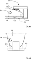
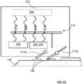
- FIG. 8A, 8B and 8C show a robotic lawn mower 100 that docks the charging station 200' for charging
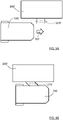
- Figure 9A, 9B and 9C show a robotic lawn mower 100 that docks the charging station 200' for entering a protect mode.
- the robotic lawn mower 100 approaches and enters the charging station 200' in a charging entering movement direction D1' and electrical contact is made with a charging transmission arrangement 210'.
- the charging transmission arrangement 210' is in the form of rods or similar that extend out from a side of the charging station 200' that is in the form of a drive-thru charging station 200'.
- the charging transmission arrangement 210' is bent in the charging entering movement direction D1'.
- the charging transmission arrangement 210' comprises a first charging member 210'a and a second charging member 210'b and an electrical switch arrangement 216, where the charging members 210'a 210'b make contact with a charging reception arrangement 156'.
- the electrical switch arrangement 216 being deactivated means that a power supply connection 232 and a boundary wire connection 230, 231 are connected to associated components 800, where the associated components 800 for example comprises one or more electrical units such as for example a boundary wire signal generator, a charger control unit and a charging unit as described previously.
- the robotic lawn mower 100 approaches and enters the charging station 200' in a protect mode entering movement direction D2' and electrical contact is in this case not made with charging transmission arrangement 210' since the charging reception arrangement 156' is not accessible for the charging transmission arrangement 210'.
- the charging transmission arrangement 210' is bent in the protect mode entering movement direction D2' which corresponds to an activation direction A1'.
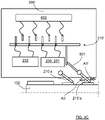
- the charging station 200' is shown with the docked robotic lawn mower 100 in a protect mode.
- the electrical switch arrangement 216 is thus activated, which means that the power supply connection 232 and the boundary wire connection 230, 231 are isolated from the associated components 800.
- the electrical switch arrangement 216 is activated by means of the second charging member 210'b being moved in an activation direction A1', where the second charging member 210'b comprises a switch activation part 801 that is adapted to activate the electrical switch arrangement 216.
- the activation member is comprised in the charging transmission arrangement 210'.
- the charging transmission arrangement 210' comprises a first charging member 210'a and a second charging member 210'b, where the electrical switch arrangement 216' is adapted to be activated by means of the second charging member 210'b, constituting the activation member, being moved in the activation direction A1'.
- the second charging member 210'b comprises a switch activation part 801 that is adapted to activate the electrical switch arrangement 216.
- the illustrated example corresponds to a typical configuration with an external power supply unit 224a, and when the electrical switch arrangement 216' is activated, a boundary wire is isolated from the boundary wire connection 230, 231 and the associated components 800 are isolated from the power supply connection 232.
- Other combinations of electrical units that are isolated when the electrical switch arrangement 216' is activated are of course conceivable as discussed previously for the first example.
- the second charging member 210'b also constitutes an activation member in accordance with the previous examples.
- an activation member there may of course be a separate activation member, it is not necessary to use a charging member.
- Such a separate activation member can be positioned a certain height.
- the activation member may have any suitable position such as under the robotic lawn mower 100 or above the robotic lawn mower 100 when docked.
- the activation member 210'b being moved in the activation direction A1' corresponds to the robotic lawn mower 100 entering the charging station 200' in the protect mode entering movement direction D2'
- the activation member 210'b being moved in a de-activation direction A2' corresponds to the robotic lawn mower 100 leaving the charging station 200' in the same direction.
- the present disclosure relates to a method for a robotic work tool system 250, which method is described in the following with reference to Figure 10 .
- the method comprises controlling S100 the movement of an outdoor robotic work tool such as a robotic lawn mower 100 and controlling S400 the robotic lawn mower 100 to move an activation member 215 at a charging station 200 used for charging a at least one rechargeable electric power source 155 of the robotic lawn mower 100, where the movement is made in an activation direction A1 such that an electrical switch arrangement 216 is activated and a protect mode is entered.
- the electrical switch arrangement 216 Upon activation, the electrical switch arrangement 216 is used for isolating at least one electric unit 220, 221, 222, 223, 224 from at least one electrical connection 230, 231, 232, 233, 234, and upon de-activation the electrical switch arrangement 216 is used for electrically connecting the electric unit 220, 221, 222, 223, 224 to said electrical connection 230, 231, 232, 233, 234.
- the robotic lawn mower 100 can activate and de-activate a switch arrangement 216 that is adapted to break an electrical connection when activated, such that at least one electric unit 220, 221, 222, 223, 224 is isolated from at least one electrical connection 230, 231, 232, 233, 234.
- a switch arrangement 216 that is adapted to break an electrical connection when activated, such that at least one electric unit 220, 221, 222, 223, 224 is isolated from at least one electrical connection 230, 231, 232, 233, 234.
- the charging station 200 is adapted for a charging entering movement direction D1, D1' and a protect mode entering movement direction D2, D2' that differs from the charging entering movement direction D1, D1'.
- Controlling S400 the robotic lawn mower 100 to move an activation member comprises controlling S410 the robotic lawn mower 100 to enter the charging station 200 in the protect mode entering movement direction D2, D2'.
- the charging entering movement direction D1 can relate to entering the charging station 200 in a forward movement direction as illustrated in Figure 4A and Figure 4B
- the protect mode entering movement direction D2 can relate to entering the charging station 200 in a rearward movement direction as illustrated in Figure 2A and Figure 2B
- the charging entering movement direction D1' can relate to the robotic lawn mower 100 entering the charging station 200 in a forward movement direction as illustrated in Figure 8A
- the protect mode entering movement direction D2' can relate to the robotic lawn mower 100 entering the charging station 200 in the forward movement direction but incoming from another direction as illustrated in Figure 9A .
- controlling S410 the robotic lawn mower 100 to enter the charging station 200 in the protect mode entering movement direction D2, D2' comprises controlling S411 the robotic lawn mower 100 to be positioned away from the charging station 200 with its back facing the activation member 215, and controlling S412 the robotic lawn mower 100 to move rearwards towards the activation member 215 until the activation member 215 is moved sufficiently to activate the electrical switch arrangement 216.
- the robotic lawn mower 100 is controlled to move away from the charging station 200 and to turn such that its back is facing the activation member 215, and then to move rearwards towards the activation member 215.
- the method comprises determining S300 if the possibility of the occurrence of a thunder storm exceeds a certain threshold. If that is the case, the method further comprises controlling S400 the robotic lawn mower 100 to move the activation member 215 in the activation direction. Alternatively, controlling S400 the robotic lawn mower 100 to press the activation member 215 can be initiated by a user that wants the robotic work tool system 250 to enter a protect mode where the electrical switch arrangement 216 is activated. This can for example be performed by means of a mobile phone application program (App) or a remote control. Both alternatives are of course conceivable for the same robotic work tool system 250.
- App mobile phone application program
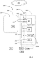
- the method comprises determining 200 the possibility of the occurrence of a thunder storm by receiving weather data from a remote server 260.
- the remote server 260 is adapted to collect weather data, for example from an Internet weather service.
- the weather data can according to some aspects be acquired from the remote server 260 by the charger control unit 222, a mobile phone App at a user terminal 261 or a local server 262.
- the lawn mower 100 and its control unit 110 can be instructed by the charger control unit 222, a mobile phone App, a remote server 260 and/or a local server 262.
- a combination is of course possible, for example where an App runs via a remote server, or when the lawn mower 100 and its control unit 110 can be instructed by several units such as both a remote server 260 and an App.
- the App can be manually operated by a user that for example hears distant thunder approaching.
- Communication between the lawn mower 100 with its control unit 110 and other units such as the charger control unit 222, a mobile phone App, a remote server 260 and/or a local server 262 can for example be made via a cell phone communication network, WiFi and/or Bluetooth.
- the lawn mower 100 may be adapted for direct access to a cell phone communication network.
- the method comprises determining S500 if the possibility of the occurrence of a thunder storm falls below a certain threshold. If that is the case, the method further comprises controlling S600 the robotic lawn mower 100 to move away from the charging station 200 such that the activation member 215 is released sufficiently, such that it is moved in a de-activation direction, to de-activate the electrical switch arrangement 216, and controlling S700 the robotic lawn mower 100 to continue its previously discontinued task.
- the robotic lawn mower 100 In case the robotic lawn mower 100 previously was charging, the robotic lawn mower 100 is controlled to move to such a position at the charging station that the robotic lawn mower 100 can continue charging the rechargeable electric power source 155 by receiving a charging current from the charging station 200. Otherwise, the robotic lawn mower 100 is controlled to continue its previously discontinued task, for example continue mowing grass or continue to move to a desired position.
- controlling the robotic lawn mower 100 to move away from the charging station 200 such that the activation member 215 is released sufficiently to de-activate the electrical switch arrangement 216 can also be performed after the lapse of a predetermined time period.
- the present disclosure also relates to an robotic lawn mower 100 adapted for a forward travelling direction D and comprising a control unit 110, a charging reception arrangement 156 adapted for making electrical contact with a charging transmission arrangement 210 of a robotic lawn mower charging station 200, and at least one environmental detector device 170.
- the control unit 110 is adapted to control the movement of the robotic lawn mower 100 in dependence of information acquired by means of the environmental detector device 170.
- the control unit 110 is further adapted to control the robotic work tool 100 to move an activation member 215 at the charging station when the control unit 110 has received corresponding instructions, where the movement is made in an activation direction such that an electrical switch arrangement 216 is activated and a protect mode is entered.
- control unit 110 is adapted to receive instructions from at least one of a charger control unit 222, a mobile phone application program App running at a user terminal 261, a remote server 260 or local server 262.
- the corresponding instructions relate to a possibility of the occurrence of a thunder storm.
- the corresponding instructions relate to user input via a user terminal 261.
- control unit 110 is adapted to control the robotic work tool 100 to move to the charging station 200 in a protect mode entering movement direction D2, D2' that differs from a charging entering movement direction D1, D1', and to move the activation member 215 in the activation direction A1 when the control unit 110 has received corresponding instructions.
- the robotic work tool 100 is adapted to move or release the activation member 215 such that it is moved sufficiently in a de-activation direction A2 when the control unit 110 has received corresponding instructions, such that the electrical switch arrangement 216 is de-activated and the protect mode is left.
- the environmental detector device 170 can comprise at least one of a radar trasnsceiver, Lidar transceiver, ultrasonic trasnsceiver and/or a camera device.
- the robotic lawn mower is an outdoor robotic work tool 100 and the robotic lawn mower charging station is an outdoor robotic work tool charging station 200.
- the charging station can be constituted by an outdoor robotic work tool interaction station 200. Except charging, such an interaction station can be constituted by a maintenance stations such as a knife sharping station, or a dumping station. The latter can for example be the case when the outdoor robotic work tool can be adapted to collect items such as leafs or golf balls. Another example of an interaction station is a marker of a lawn mower off-limit area such as an area around a plant that should be left.
- Figure 7 shows a computer program product 500 comprising computer executable instructions 510 stored on media 520 to execute any of the methods disclosed herein.
- the computer program product 500 can be solely or at least partly implemented for at least one of a charger control unit 222, a user terminal 261, a remote server 260 and/or a local server 262.
- a local server 262 can for example be constituted by an indoor user computer unit.
- the outdoor robotic work tool interaction station 200 is an outdoor robotic work tool charging station, where the control unit 110 of the robotic lawn mower 100 is adapted to control the movement of the robotic lawn mower 100 such that it moves to such a position at the outdoor robotic work tool charging station 200 such that the charging reception arrangement 156 can make electrical contact with the charging transmission arrangement 210.
- the robotic lawn mower 100 can then receive a charging current from the outdoor robotic work tool charging station 200.
- the present disclosure also relates to a robotic work tool system 250 comprising the outdoor robotic work tool charging station 200 and the outdoor robotic work tool 100 according the above.
- the robotic work tool system 250 further comprises said electric unit 220, 221, 222, 223, 224 that is adapted to be isolated from at least one electrical connection 230, 231, 232, 233, 234 upon activation of the electrical switch arrangement 216.
- the robotic work tool system 250 further comprises at least one of a remote server 260, a user terminal 261, or a local server 262, where the control unit 110 of the outdoor robotic work tool 100 is adapted to receive instructions from at least one of the charger control unit 222, the mobile phone application program (App) running at the user terminal 261, the remote server 260 or the local server 262.
- App mobile phone application program
- the electrical switch arrangement 216 upon activation, is adapted to connect at least one electrical connection 230 to a ground connection 240.
- a ground connection 240 This provides a further protection, since one or more electric units can be securely grounded.
- the boundary wire 220 can be switched to be directly connected to ground instead of being connected to the boundary wire signal generator 221.
- the ground connection 240 comprises a metal rod that is inserted into the ground.
- the electrical switch arrangement 216 can be realized in many different ways, as evident to the skilled person.
- the electrical switch arrangement 216 may comprise different types of individual switches depending on if a certain switch is adapted to open and close a low-power connection, a high power connection or a data signal connection.
- the activation member 215 can be biased by a resilient member, such as a spring, that urges the activation member 215 in the de-activation direction A2. Then the activation member 215 moves in the de-activation direction A2 when being released by the robotic lawn mower, otherwise the activation member 215 is moved in the de-activation direction A2 by the robotic lawn mower.
- a resilient member such as a spring
- the activation member 215 can be formed in many ways.
- the activation member 215 is shown as protruding a protruding member, but it can also be formed to be flush with, or as an indent in, a surface of the charging station 200.
- the activation member 215 is accessible by the robotic lawn mower 100 when approaching the charging station 200 in the protect mode entering movement direction D2.
- the activation member 215 has been described to be mechanically operated in different ways, but other alternatives are of course conceivable.
- the robotic lawn mower 100 is adapted to move an activation member 215" electromechanically, where lawn mower electric contact members 1110a, 1110b, for example constituted by charging skids or by separate contact members comprised in the robotic lawn mower 100, are adapted to contact charging station contact members 1120a, 1120b, for example constituted by a charging transmission arrangement or by separate contact members, when the protect mode is about to be entered.
- the robotic lawn mower 100 is adapted to transmit a first electric current to a solenoid arrangement 1130 in the charging station 200" via the electric contact members 1110a, 1110b; 1120a, 1120b such that the activation member 215" is moved in the activation direction A1" by the solenoid arrangement 1130.
- the robotic lawn mower 100 is adapted to transmit a second electric current to the solenoid arrangement 1130 in the charging station 200" via the electric contact members 1110a, 1110b; 1120a, 1120b such that the activation member 215" is moved in the de-activation direction A2" by the solenoid arrangement 1130.
- the activation member 215" is an internal component of the charging station 200", not being physically accessible from the outside, being movable by means of the solenoid arrangement 1130".
- the protect mode can be entered directly from a charging mode.
- the robotic lawn mower 100 then communicates with the charging station control unit 222, ordering the charging station's control unit 222 to discontinue the charging mode and connect the charging station contact members 1120a, 1120b to the solenoid arrangement 1130. This can be accomplished by means of an electrically controllable switch comprised in the charging station.
- the charging station 200" comprises charging station contact members 1120a, 1120b that are adapted to contact robotic work tool electric contact members 1110a, 1110b comprised in an outdoor robotic work tool 100, when the protect mode is about to be entered, where the charging station 200" is adapted to receive a first electric current to a solenoid arrangement 1130 comprised in the charging station 200" via the electric contact members 1110a, 1110b; 1120a, 1120b such that the activation member 215" is moved in the activation direction A1" by the solenoid arrangement 1130, where furthermore the charging station 200" is adapted to receive a second electric current to the solenoid arrangement 1130 via the electric contact members 1110a, 1110b; 1120a, 1120b such that the activation member 215" is moved in the de-activation direction A2" by the solenoid arrangement 1130 such that the protect mode is left.
- This external input is according to some aspects, provided by means of the robotic lawn mower 100 that still is operational by means of its battery power.
Landscapes
- Engineering & Computer Science (AREA)
- Life Sciences & Earth Sciences (AREA)
- Environmental Sciences (AREA)
- Power Engineering (AREA)
- Transportation (AREA)
- Mechanical Engineering (AREA)
- Harvester Elements (AREA)
- Charge And Discharge Circuits For Batteries Or The Like (AREA)
Abstract
Description
- The present disclosure relates to outdoor robotic work tool system with an outdoor robotic work tool and a work tool charging station, and in particular high voltage electrical surge protections for the outdoor robotic work tool and the work tool charging station with associated electrical components, especially electrical surges which are due to one or more lightning strikes during a thunder storm. The outdoor robotic work tool can for example be constituted by a robotic lawn mower.
- Automated or robotic power tools such as robotic lawn mowers are becoming increasingly more popular. In a typical deployment a work area, such as a garden, the work area can be enclosed by a boundary wire with the purpose of keeping the robotic lawn mower inside the work area. An electric control signal may be transmitted through the boundary wire thereby generating an (electro-) magnetic field emanating from the boundary wire. The robotic lawn mower is typically arranged with one or more sensors adapted to sense the control signal. Other types of navigation systems can be used instead of, or in combination with a boundary wire. Such navigation systems can for example be based on satellite navigation systems and/or local radio beacons or image processing such as Visual Simultaneous Localization and Mapping (VSLAM).
- The robotic lawn mower can then cut grass on a user's lawn automatically and can be charged automatically without intervention of the user, and no longer needs to be manually managed after being set once. The robotic lawn mower typically comprises charging skids for contacting corresponding contact plates in a charging station when docking into the charging station for receiving a charging current through, and possibly also for transferring information by means of electrical communication between the charging station and the robotic lawn mower.
- During a thunder storm, a lightning strike may damage robotic lawn mower equipment such as the robotic lawn mower itself, especially during charging, power supply units, loop generators and other lawn mower system electronics. This is due to high voltage electrical surges, inflicted from lightning strikes, entering the robotic lawn mower equipment via the electrical mains and/or the boundary wire if used. The document
SE 539127 - There is thus a need to provide an improved high voltage electrical surge protection arrangement for an outdoor robotic work tool system, such as a robotic lawn mower system.
- The object of the present disclosure is to provide an outdoor robotic work tool system, such as a robotic lawn mower system, comprising an improved high voltage electrical surge protection arrangement.
- This object is achieved by means of method for a robotic work tool system, where the method comprises controlling the movement of an outdoor robotic work tool and controlling the outdoor robotic work tool to move an activation member at an outdoor robotic work tool charging station used for charging at least one rechargeable electric power source of the outdoor robotic work tool. The movement is made in an activation direction such that an electrical switch arrangement is activated and a protect mode is entered, wherein, upon activation, the electrical switch arrangement is used for isolating at least one electric unit from at least one electrical connection. Upon de-activation, the electrical switch arrangement is used for electrically connecting the electric unit to said electrical connection.
- This way, the outdoor robotic work tool can activate and de-activate a switch arrangement that is adapted to break an electrical connection when activated, such that at least one electric is isolated from at least one electrical connection. This enables a possibility to protect electrical components both in the charging station and in the outdoor robotic work tool, where such a protection for example is desired in the case of a thunderstorm condition where electrical surges can occur due to lightning strikes. According to some aspects, the charging station is adapted for a charging entering movement direction and a protect mode entering movement direction that differs from the charging entering movement direction. Controlling the outdoor robotic work tool to move an activation member comprises controlling the outdoor robotic work tool to enter the charging station in the protect mode entering movement direction.
- This way, there are distinct movement directions that are associated with a charging mode and a protect mode.
- According to some aspects, controlling the outdoor robotic work tool to enter the charging station in the protect mode entering movement direction comprises controlling the outdoor robotic work tool to be positioned away from the charging station with its back facing the activation member, and controlling the outdoor robotic work tool to move rearwards towards the activation member until the activation member is moved sufficiently to activate the electrical switch arrangement.
- This means that if the outdoor robotic work tool is in motion, it is controlled to move to the charging station in a suitable fashion for entering the protect mode.
- According to some aspects, the method comprises determining the possibility of the occurrence of a thunder storm by receiving weather data from a remote server.
- According to some aspects, the method comprises determining if the possibility of the occurrence of a thunder storm exceeds a certain threshold, and if that is the case, the method comprises controlling the outdoor robotic work tool to move the activation member in the activation direction.
- This means that the protect mode is entered when the possibility of the occurrence of a thunder storm has been determined to exceed a certain threshold.
- According to some aspects, the method comprises determining if the possibility of the occurrence of a thunder storm falls below a certain threshold. If that is the case, the method further comprises controlling the outdoor robotic work tool to move away from the charging station such that the activation member is released sufficiently, such that it is moved in a de-activation direction, to de-activate the electrical switch arrangement, and controlling the outdoor robotic work tool to continue its previously discontinued task.
- This means that the protect mode is left when the possibility of the occurrence of a thunder storm has been determined to fall below a certain threshold.
- The present disclosure also relates to outdoor robotic work tool charging stations, outdoor robotic work tools and robotic work tool systems that are associated with the above advantages.
- The present disclosure will now be described more in detail with reference to the appended drawings, where:
- Figure 1A
- shows a perspective side view of a robotic lawn mower;
- Figure 1B
- shows a schematic overview of the robotic lawn mower;
- Figure 2A
- shows a schematic side view of a robotic lawn mower charging station with a robotic lawn mower in a protection positon where an electrical switch arrangement is activated;
- Figure 2B
- shows a schematic top view of
Figure 2A ; - Figure 3
- shows a schematic illustration of a robotic work tool system with an activated electrical switch arrangement;
- Figure 4A
- shows a schematic side view of a robotic lawn mower charging station with a robotic lawn mower in a charging positon where an electrical switch arrangement is de-activated;
- Figure 4B
- shows a schematic top view of
Figure 4A ; - Figure 5
- shows a schematic illustration of a robotic work tool system with a deactivated electrical switch arrangement;
- Figure 6A
- shows a schematic illustration of a de-activated electrical switch arrangement;
- Figure 6B
- shows a schematic illustration of an activated electrical switch arrangement;
- Figure 7
- shows a computer program product;
- Figure 8A
- shows a schematic illustration of a lawn mower approaching and entering an alternative charging station in a charging entering movement direction;
- Figure 8B
- shows a schematic illustration of a lawn mower in a charging mode, docked to the alternative charging station;
- Figure 8C
- shows a schematic illustration of a the alternative charging station in the charging mode;
- Figure 9A
- shows a schematic illustration of a lawn mower approaching and entering an alternative charging station in a protect mode entering movement direction;
- Figure 9B
- shows a schematic illustration of a lawn mower in a protect mode, docked to the alternative charging station;
- Figure 9C
- shows a schematic illustration of a the alternative charging station in the protect mode;
- Figure 10
- shows a flowchart for methods according to the present disclosure; and
- Figure 11
- shows a schematic illustration of an alternative charging station in the protect mode, the activation member being electromechanically operated.
- Aspects of the present disclosure will now be described more fully hereinafter with reference to the accompanying drawings. The different devices, systems, computer programs and methods disclosed herein can, however, be realized in many different forms and should not be construed as being limited to the aspects set forth herein. Like numbers in the drawings refer to like elements throughout.
- The terminology used herein is for describing aspects of the disclosure only and is not intended to limit the invention. As used herein, the singular forms "a", "an" and "the" are intended to include the plural forms as well, unless the context clearly indicates otherwise.
- It should be noted that even though the description given herein will be focused on robotic lawn mowers, the teachings herein may also be applied to any type of outdoor robotic work tool, such as for example robotic ball collectors, robotic mine sweepers and robotic farming equipment.
-
Figure 1A shows a perspective view of arobotic lawn mower 100 andFigure 1B shows a schematic overview of therobotic lawn mower 100. Therobotic lawn mower 100 is adapted for a forward travelling direction D, has amain body 140 and a plurality ofwheels 130; in this example therobotic lawn mower 100 has fourwheels 130, two front wheels and two rear wheels. Therobotic lawn mower 100 comprises acontrol unit 110 and at least oneelectric motor 150, where at least some of thewheels 130 are drivably connected to at least oneelectric motor 150. It should be noted that even if the description herein is focused on electric motors, combustion engines may alternatively be used in combination with an electric motor arrangement. Therobotic lawn mower 100 may be a multi-chassis type or a mono-chassis type. A multi-chassis type comprises two or more body parts that are movable with respect to one another. A mono-chassis type comprises only one main body part. - In this example embodiment, the
robotic lawn mower 100 is of a mono-chassis type, having amain body part 140. Themain body part 140 substantially houses all components of therobotic lawn mower 100. - The
robotic lawn mower 100 also comprises agrass cutting device 160, such as a rotating blade or adisc 160 with a plurality of separate rotating blades driven by acutter motor 165. Therobotic lawn mower 100 also has at least one rechargeable electric power source such as abattery 155 for providing power to theelectric motor arrangement 150 and/or thecutter motor 165. - The
battery 155 is arranged to be charged by means of received charging current from a charging station (not shown), received through chargingskids 156 or other suitable charging connectors, generally constituted by a chargingreception arrangement 156. Inductive charging without galvanic contact, only by means of electric contact, is also conceivable. The battery is generally constituted by a rechargeableelectric power source 155 that comprises one or more batteries that can be separately arranged or be arranged in an integrated manner to form a combined battery. - According to some aspects, the
robotic lawn mower 100 may further comprise at least onenavigation sensor arrangement 175 in a previously known manner, for example comprising a satellite navigation sensor in the form of a GPS (Global Positioning System) device or other Global Navigation Satellite System (GNSS) device, according to some aspects for example using Real Time Kinematic (RTK). - According to some aspects, the
robotic lawn mower 100 further comprises at least oneenvironment detection device 170. In this example,radar transceivers 170 are provided and adapted to transmit signals and to receive reflected signals in a previously well-known manner. To enable this, according to some aspects, eachradar transceiver 170 comprises a corresponding transmitter arrangement and receiver arrangement together with other necessary circuitry in a well-known manner. - For this purpose, the
control unit 110 is adapted to control theenvironment detection device 170 and to control the speed and direction of therobotic lawn mower 100 in dependence of information acquired by means of the of theenvironment detection device 170 when therobotic lawn mower 100 is moving. - Generally, the
control unit 110 is adapted to at least partly process input data from at least oneenvironmental detection device 170. - With reference also to
Figure 2A and Figure 2B that show a side view and a corresponding top view of a chargingstation 200 and therobotic lawn mower 100, the chargingstation 200 comprises a chargingtransmission arrangement 210 that is adapted to transfer a charging current to the chargingreception arrangement 156. With reference also toFigure 3 that shows a schematic illustration of a roboticwork tool system 250, the chargingstation 200 comprises anelectrical switch arrangement 216. - The
electrical switch arrangement 216 is adapted to isolate at least oneelectric unit electrical connection electric unit electrical connection activation member 215 is adapted to activate theelectrical switch arrangement 216 when being moved in an activation direction A1, according to some aspects by being pushed, towards the chargingstation 200. Theelectrical switch arrangement 216 is adapted to be activated by therobotic lawn mower 100 when therobotic lawn mower 100 moves theactivation member 215 sufficiently in the activation direction A1, and to be de-activated when therobotic lawn mower 100 moves or releases theactivation member 215 such that it is moved sufficiently in a de-activation direction A2. - In this context, the terms sufficiently relates to an extent that confers a mode change of the
electrical switch arrangement 216, such that theelectrical switch arrangement 216 switches from one switch state to another switch state. According to some aspects, theactivation member 215 being moved in the activation direction A1 corresponds to therobotic lawn mower 100 entering the chargingstation 200 in a protect mode entering movement direction D2, and theactivation member 215 being moved in the de-activation direction A2 corresponds to therobotic lawn mower 100 leaving the chargingstation 200, according to some aspects in the opposite direction. - In this way, the
robotic lawn mower 100 can activate and de-activate theswitch arrangement 216 that is adapted to break an electrical connection when activated, such that electrical components can be protected. Such a protection is for example desired in the case of a thunderstorm condition where electrical surges can occur due to lightning strikes. - As shown in
Figure 3 that illustrates a roboticwork tool system 250 in a schematic manner, there is awork area 225 that is enclosed by aboundary wire 220 with the purpose of keeping therobotic lawn mower 100 inside thework area 225. An electric control signal may be transmitted through theboundary wire 220 thereby generating a magnetic field emanating from theboundary wire 220. The roboticwork tool system 250 comprises a boundarywire signal generator 221 that is connected to theboundary wire 220 and is adapted to handle all signaling to and from theboundary wire 220. Therobotic lawn mower 100 comprises a boundary wire controlsignal sensor arrangement 228 that is adapted to detect boundary wire signals, where the boundary wire controlsignal sensor arrangement 228 comprises one or more sensor elements, where there for example can be a plurality of distributed sensor elements. - Each electric unit as mentioned above can be constituted by one or more different types of units. For example the electric unit can be constituted by one of the
boundary wire 220, the boundarywire signal generator 221, acharger control unit 222, a chargingunit 223 and apower supply unit 224 that is connected to amains power outlet 235. This means that, for example, theboundary wire 220 can be disconnected from the boundarywire signal generator 221, thereby protecting the boundarywire signal generator 221 in case a lightning strike causes an electrical surge in theboundary wire 220. - One or more of the above electric units can be disconnected and isolated by means of the
electrical switch arrangement 216 as described above. If, for example, thepower supply unit 224 is not comprised in the chargingstation 200 but is constituted by a separate external unit that is remote from the chargingstation 200, thepower supply unit 224 may not be possible to isolate from themains power outlet 235 by means of theelectrical switch arrangement 216. This is illustrated by an alternativepower supply unit 224a, indicated by dashed lines, where the alternativepower supply unit 224a is an externalpower supply unit 224a that can be an indoor unit or placed remote from the chargingstation 200 in some other manner, for example connected to an outdoor mains power outlet. - In case of the robotic
work tool system 250 being arranged without a boundary wire and solely depending on anavigation sensor arrangement 175 as described above, there is of course no need to isolate aboundary wire 220 and boundarywire signal generator 221 since these in that case are not comprised in the roboticwork tool system 250. Many different variations are of course possible as evident to the skilled person. For example, the roboticwork tool system 250 may be arranged for anavigation sensor arrangement 175 together with a relatively small boundary wire at the charging station, only be being used to aid thelawn mower 100 when docking to the chargingstation 200, - Which electric units that are adapted to be disconnected and isolated by means of the
electrical switch arrangement 216 is thus dependent on which electric units that are comprised in the roboticwork tool system 250 and are accessible for theelectrical switch arrangement 216, as well as on which electric units that are considered necessary or desired to protect from electrical surges of the kind described above. Practical aspects and cost aspects are also important when determining which electric units that are adapted to be disconnected and isolated by means of theelectrical switch arrangement 216. - According to some aspects and as illustrated in
Figure 6A and Figure 6B , in order to provide sufficient electrical isolation, theelectrical switch arrangement 216 is adapted to provide a mechanical separation S1, S2, constituting an isolation distance, between adjacent electrical conductors C1, C2 of at least 5 cm when activated, and preferably at least 10 cm. InFigure 6A , theelectrical switch arrangement 216 is schematically indicated as de-activated, closing a connection between the two adjacent electrical conductors C1, C2. These electrical conductors C1, C2 are indicated in a general manner and can connect any electric unit, for example one of the electrical conductors C1 can be an electrical connector leading to theboundary wire 220 and the other electrical conductor C2 can be a connection to the boundarywire signal generator 221. - According to some aspects, the
activation member 215 is connected to theelectrical switch arrangement 216 either directly or via a mechanical linkage (not shown). A mechanical linkage can be adapted to make it easier to accomplish a sufficient isolation distance. - According to some aspects, the
electrical connection boundary wire connection power supply connection 232, amains power connection 233 and adata signal bus 234. In the case of thepower supply unit 224a being externalpower supply unit 224a, there is an alternativepower supply connection 232a, indicated with dashed lines, that enters the charging station. - Each electrical connection normally comprises one or more electrical wires, for example a signal wire and a ground wire such as a live wire and a neutral wire, for example wires with different AC or DC voltages. In
Figure 3 andFigure 5 this is schematically indicated by one line only for the connections, except the boundary wire connection that is indicated with two lines. - As an example, when the
electrical switch arrangement 216 is activated, this means that an electric connection that is isolated from theboundary wire 220 is aboundary wire connection wire signal generator 221, thecharger control unit 222 and/or thecharger unit 223 is apower supply connection 232, and that an electric connection that is isolated from thepower supply unit 224 is amains power connection 233. Furthermore, when theelectrical switch arrangement 216 is activated, this also means that an electric connection that is isolated from thecharger control unit 222 is adata signal bus 234. The data signalbus 234 can be arranged for input of data signals to thecharger control unit 222, output of data signals from thecharger control unit 222, or both. - According to some aspects, an example of a typical configuration can be a robotic work tool system with an external
power supply unit 224a, and when theelectrical switch arrangement 216 is activated, theboundary wire 220 is isolated from theboundary wire connection wire signal generator 221, thecharger control unit 222 and/or thecharger unit 223 are isolated from thepower supply connection 232a. In this case, no other electrical units are isolated when theelectrical switch arrangement 216 is activated. - Generally, when the
electrical switch arrangement 216 is activated, the chargingstation 200 is not in operation, needing external input to be reinstated into operation. This external input is according to some aspects, provided by means of therobotic lawn mower 100 that still is operational by means of its battery power as will be described below. - As illustrated in
Figure 2A , the chargingtransmission arrangement 210 of the chargingstation 200 is not engaged when theelectrical switch arrangement 216 is activated. When theelectrical switch arrangement 216 is to be de-activated, therobotic lawn mower 100 is controlled to move away from the chargingstation 200 and to either move away to continue an interrupted task such as grass mowing, or to turn around and engage the chargingstation 200 such that the chargingreception arrangement 156 can make electrical contact with the chargingtransmission arrangement 210 as illustrated inFigure 4A and Figure 4B . Here it is indicated that when therobotic lawn mower 100 is charging, theactivation member 215 is not engaged, and theelectrical switch arrangement 216 is de-activated as illustrated inFigure 5 . According to some aspects, therobotic lawn mower 100 then enters the chargingstation 200 in a charging entering movement direction D1 and initiates a charging mode. In this case, theactivation member 215 is not engaged by means of exterior design of therobotic lawn mower 100. - As shown in
Figure 2A , according to some aspects there is amagnet 226 positioned in the chargingstation 200, where themagnet 226 is detectable by amagnet field detector 227 comprised in therobotic lawn mower 100 when therobotic lawn mower 100 is positioned such that theswitch arrangement 216 is activated. The purpose of this arrangement is that thecontrol unit 110 of therobotic lawn mower 100 can determine its position more easily when theswitch arrangement 216 is to be de-activated by therobotic lawn mower 100 moving away from the chargingstation 200. For example, thecontrol unit 110 can then determine whether therobotic lawn mower 100 has been moved. - If the
control unit 110 can determine that therobotic lawn mower 100 is in a correct position when theswitch arrangement 216 is to be de-activated, thecontrol unit 110 can control therobotic lawn mower 100 to move away from the chargingstation 200 such that theactivation member 215 is released and the boundarywire signal generator 221 re-connected to theboundary wire 220 and to thepower supply unit 224 such that thecontrol unit 110 can determine the position of therobotic lawn mower 100 by means of theboundary wire 220. - An alternative charging station will now be described with reference to
Figure 8A, 8B and8C , which show arobotic lawn mower 100 that docks the charging station 200' for charging andFigure 9A, 9B and9C , which show arobotic lawn mower 100 that docks the charging station 200' for entering a protect mode. - In
Figure 8A and Figure 8B , therobotic lawn mower 100 approaches and enters the charging station 200' in a charging entering movement direction D1' and electrical contact is made with a charging transmission arrangement 210'. The charging transmission arrangement 210' is in the form of rods or similar that extend out from a side of the charging station 200' that is in the form of a drive-thru charging station 200'. When electrical contact is made with charging transmission arrangement 210', the charging transmission arrangement 210' is bent in the charging entering movement direction D1'. - As shown in
Figure 8C that is a schematic representation of the charging station 200' with the dockedrobotic lawn mower 100 in a charging mode, the charging transmission arrangement 210' comprises a first charging member 210'a and a second charging member 210'b and anelectrical switch arrangement 216, where the charging members 210'a 210'b make contact with a charging reception arrangement 156'. Theelectrical switch arrangement 216 being deactivated means that apower supply connection 232 and aboundary wire connection components 800, where the associatedcomponents 800 for example comprises one or more electrical units such as for example a boundary wire signal generator, a charger control unit and a charging unit as described previously. - In
Figure 9A and Figure 9B , therobotic lawn mower 100 approaches and enters the charging station 200' in a protect mode entering movement direction D2' and electrical contact is in this case not made with charging transmission arrangement 210' since the charging reception arrangement 156' is not accessible for the charging transmission arrangement 210'. Here, the charging transmission arrangement 210' is bent in the protect mode entering movement direction D2' which corresponds to an activation direction A1'. - As shown in
Figure 9C that corresponds toFigure 8C , the charging station 200' is shown with the dockedrobotic lawn mower 100 in a protect mode. Theelectrical switch arrangement 216 is thus activated, which means that thepower supply connection 232 and theboundary wire connection components 800. In this example, theelectrical switch arrangement 216 is activated by means of the second charging member 210'b being moved in an activation direction A1', where the second charging member 210'b comprises aswitch activation part 801 that is adapted to activate theelectrical switch arrangement 216. - This means that in this example the activation member is comprised in the charging transmission arrangement 210'. According to some aspects, the charging transmission arrangement 210' comprises a first charging member 210'a and a second charging member 210'b, where the electrical switch arrangement 216' is adapted to be activated by means of the second charging member 210'b, constituting the activation member, being moved in the activation direction A1'. The second charging member 210'b comprises a
switch activation part 801 that is adapted to activate theelectrical switch arrangement 216. - The illustrated example corresponds to a typical configuration with an external
power supply unit 224a, and when the electrical switch arrangement 216' is activated, a boundary wire is isolated from theboundary wire connection components 800 are isolated from thepower supply connection 232. Other combinations of electrical units that are isolated when the electrical switch arrangement 216' is activated are of course conceivable as discussed previously for the first example. - Here, the second charging member 210'b also constitutes an activation member in accordance with the previous examples. There may of course be a separate activation member, it is not necessary to use a charging member. Such a separate activation member can be positioned a certain height. Generally, irrespective of if the activation member is constituted by a charging member or not, it may have any suitable position such as under the
robotic lawn mower 100 or above therobotic lawn mower 100 when docked. - According to some aspects, the activation member 210'b being moved in the activation direction A1' corresponds to the
robotic lawn mower 100 entering the charging station 200' in the protect mode entering movement direction D2', and the activation member 210'b being moved in a de-activation direction A2' corresponds to therobotic lawn mower 100 leaving the charging station 200' in the same direction. - In order to accomplish the above, the present disclosure relates to a method for a robotic
work tool system 250, which method is described in the following with reference toFigure 10 . The method comprises controlling S100 the movement of an outdoor robotic work tool such as arobotic lawn mower 100 and controlling S400 therobotic lawn mower 100 to move anactivation member 215 at a chargingstation 200 used for charging a at least one rechargeableelectric power source 155 of therobotic lawn mower 100, where the movement is made in an activation direction A1 such that anelectrical switch arrangement 216 is activated and a protect mode is entered. Upon activation, theelectrical switch arrangement 216 is used for isolating at least oneelectric unit electrical connection electrical switch arrangement 216 is used for electrically connecting theelectric unit electrical connection - In this way, the
robotic lawn mower 100 can activate and de-activate aswitch arrangement 216 that is adapted to break an electrical connection when activated, such that at least oneelectric unit electrical connection station 200 and in therobotic lawn mower 100 can be protected, where such a protection for example is desired in the case of a thunderstorm condition where electrical surges can occur due to lightning strikes. - According to some aspects, the charging
station 200 is adapted for a charging entering movement direction D1, D1' and a protect mode entering movement direction D2, D2' that differs from the charging entering movement direction D1, D1'. Controlling S400 therobotic lawn mower 100 to move an activation member comprises controlling S410 therobotic lawn mower 100 to enter the chargingstation 200 in the protect mode entering movement direction D2, D2'. - This means that the charging entering movement direction D1 can relate to entering the charging
station 200 in a forward movement direction as illustrated inFigure 4A and Figure 4B , and the protect mode entering movement direction D2 can relate to entering the chargingstation 200 in a rearward movement direction as illustrated inFigure 2A and Figure 2B . Alternatively, the charging entering movement direction D1' can relate to therobotic lawn mower 100 entering the chargingstation 200 in a forward movement direction as illustrated inFigure 8A , and the protect mode entering movement direction D2' can relate to therobotic lawn mower 100 entering the chargingstation 200 in the forward movement direction but incoming from another direction as illustrated inFigure 9A . - According to some aspects, controlling S410 the
robotic lawn mower 100 to enter the chargingstation 200 in the protect mode entering movement direction D2, D2' comprises controlling S411 therobotic lawn mower 100 to be positioned away from the chargingstation 200 with its back facing theactivation member 215, and controlling S412 therobotic lawn mower 100 to move rearwards towards theactivation member 215 until theactivation member 215 is moved sufficiently to activate theelectrical switch arrangement 216. - This means that if the
robotic lawn mower 100 is in motion, either mowing grass or moving to or from a work site, therobotic lawn mower 100 is controlled to move to the chargingstation 200 with its back facing theactivation member 215, and to move rearwards towards theactivation member 215 in accordance with the example described with reference toFigure 2A and Figure 2B . - If the
robotic lawn mower 100 already is charging in the chargingstation 200, therobotic lawn mower 100 is controlled to move away from the chargingstation 200 and to turn such that its back is facing theactivation member 215, and then to move rearwards towards theactivation member 215. - According to some aspects, the method comprises determining S300 if the possibility of the occurrence of a thunder storm exceeds a certain threshold. If that is the case, the method further comprises controlling S400 the
robotic lawn mower 100 to move theactivation member 215 in the activation direction. Alternatively, controlling S400 therobotic lawn mower 100 to press theactivation member 215 can be initiated by a user that wants the roboticwork tool system 250 to enter a protect mode where theelectrical switch arrangement 216 is activated. This can for example be performed by means of a mobile phone application program (App) or a remote control. Both alternatives are of course conceivable for the same roboticwork tool system 250. - According to some aspects, the method comprises determining 200 the possibility of the occurrence of a thunder storm by receiving weather data from a
remote server 260. For this purpose, theremote server 260 is adapted to collect weather data, for example from an Internet weather service. The weather data can according to some aspects be acquired from theremote server 260 by thecharger control unit 222, a mobile phone App at auser terminal 261 or alocal server 262. Thelawn mower 100 and itscontrol unit 110 can be instructed by thecharger control unit 222, a mobile phone App, aremote server 260 and/or alocal server 262. A combination is of course possible, for example where an App runs via a remote server, or when thelawn mower 100 and itscontrol unit 110 can be instructed by several units such as both aremote server 260 and an App. The App can be manually operated by a user that for example hears distant thunder approaching. - Communication between the
lawn mower 100 with itscontrol unit 110 and other units such as thecharger control unit 222, a mobile phone App, aremote server 260 and/or alocal server 262 can for example be made via a cell phone communication network, WiFi and/or Bluetooth. Thelawn mower 100 may be adapted for direct access to a cell phone communication network. - According to some aspects, the method comprises determining S500 if the possibility of the occurrence of a thunder storm falls below a certain threshold. If that is the case, the method further comprises controlling S600 the
robotic lawn mower 100 to move away from the chargingstation 200 such that theactivation member 215 is released sufficiently, such that it is moved in a de-activation direction, to de-activate theelectrical switch arrangement 216, and controlling S700 therobotic lawn mower 100 to continue its previously discontinued task. - In case the
robotic lawn mower 100 previously was charging, therobotic lawn mower 100 is controlled to move to such a position at the charging station that therobotic lawn mower 100 can continue charging the rechargeableelectric power source 155 by receiving a charging current from the chargingstation 200. Otherwise, therobotic lawn mower 100 is controlled to continue its previously discontinued task, for example continue mowing grass or continue to move to a desired position. - According to some aspects, controlling the
robotic lawn mower 100 to move away from the chargingstation 200 such that theactivation member 215 is released sufficiently to de-activate theelectrical switch arrangement 216 can also be performed after the lapse of a predetermined time period. - The present disclosure also relates to an
robotic lawn mower 100 adapted for a forward travelling direction D and comprising acontrol unit 110, a chargingreception arrangement 156 adapted for making electrical contact with a chargingtransmission arrangement 210 of a robotic lawnmower charging station 200, and at least oneenvironmental detector device 170. Thecontrol unit 110 is adapted to control the movement of therobotic lawn mower 100 in dependence of information acquired by means of theenvironmental detector device 170. Thecontrol unit 110 is further adapted to control therobotic work tool 100 to move anactivation member 215 at the charging station when thecontrol unit 110 has received corresponding instructions, where the movement is made in an activation direction such that anelectrical switch arrangement 216 is activated and a protect mode is entered. - According to some aspects, the
control unit 110 is adapted to receive instructions from at least one of acharger control unit 222, a mobile phone application program App running at auser terminal 261, aremote server 260 orlocal server 262. - According to some aspects, the corresponding instructions relate to a possibility of the occurrence of a thunder storm.
- According to some aspects, the corresponding instructions relate to user input via a
user terminal 261. - According to some aspects, the
control unit 110 is adapted to control therobotic work tool 100 to move to the chargingstation 200 in a protect mode entering movement direction D2, D2' that differs from a charging entering movement direction D1, D1', and to move theactivation member 215 in the activation direction A1 when thecontrol unit 110 has received corresponding instructions. - According to some aspects, the
robotic work tool 100 is adapted to move or release theactivation member 215 such that it is moved sufficiently in a de-activation direction A2 when thecontrol unit 110 has received corresponding instructions, such that theelectrical switch arrangement 216 is de-activated and the protect mode is left. - The
environmental detector device 170 can comprise at least one of a radar trasnsceiver, Lidar transceiver, ultrasonic trasnsceiver and/or a camera device. - Generally, the robotic lawn mower is an outdoor
robotic work tool 100 and the robotic lawn mower charging station is an outdoor robotic worktool charging station 200. - According to some aspects, the charging station can be constituted by an outdoor robotic work
tool interaction station 200. Except charging, such an interaction station can be constituted by a maintenance stations such as a knife sharping station, or a dumping station. The latter can for example be the case when the outdoor robotic work tool can be adapted to collect items such as leafs or golf balls. Another example of an interaction station is a marker of a lawn mower off-limit area such as an area around a plant that should be left. - There can of course be two or more different outdoor robotic work
tool interaction stations 200 that can have different purposes. -
Figure 7 shows acomputer program product 500 comprising computerexecutable instructions 510 stored onmedia 520 to execute any of the methods disclosed herein. According to some aspects, thecomputer program product 500 can be solely or at least partly implemented for at least one of acharger control unit 222, auser terminal 261, aremote server 260 and/or alocal server 262. Alocal server 262 can for example be constituted by an indoor user computer unit. - According to some aspects, the outdoor robotic work
tool interaction station 200 is an outdoor robotic work tool charging station, where thecontrol unit 110 of therobotic lawn mower 100 is adapted to control the movement of therobotic lawn mower 100 such that it moves to such a position at the outdoor robotic worktool charging station 200 such that the chargingreception arrangement 156 can make electrical contact with the chargingtransmission arrangement 210. Therobotic lawn mower 100 can then receive a charging current from the outdoor robotic worktool charging station 200. - The present disclosure also relates to a robotic
work tool system 250 comprising the outdoor robotic worktool charging station 200 and the outdoorrobotic work tool 100 according the above. The roboticwork tool system 250 further comprises saidelectric unit electrical connection electrical switch arrangement 216. - According to some aspects, the robotic
work tool system 250 further comprises at least one of aremote server 260, auser terminal 261, or alocal server 262, where thecontrol unit 110 of the outdoorrobotic work tool 100 is adapted to receive instructions from at least one of thecharger control unit 222, the mobile phone application program (App) running at theuser terminal 261, theremote server 260 or thelocal server 262. - The present disclosure is not limited to the above, but may vary freely within the scope of the appended claims. For example, as indicated in
Figure 3 , upon activation, theelectrical switch arrangement 216 is adapted to connect at least oneelectrical connection 230 to aground connection 240. This provides a further protection, since one or more electric units can be securely grounded. For example, theboundary wire 220 can be switched to be directly connected to ground instead of being connected to the boundarywire signal generator 221. According to some aspects, theground connection 240 comprises a metal rod that is inserted into the ground. - The
electrical switch arrangement 216 can be realized in many different ways, as evident to the skilled person. Theelectrical switch arrangement 216 may comprise different types of individual switches depending on if a certain switch is adapted to open and close a low-power connection, a high power connection or a data signal connection. - According to some aspects, the
activation member 215 can be biased by a resilient member, such as a spring, that urges theactivation member 215 in the de-activation direction A2. Then theactivation member 215 moves in the de-activation direction A2 when being released by the robotic lawn mower, otherwise theactivation member 215 is moved in the de-activation direction A2 by the robotic lawn mower. - According to some aspects, the
activation member 215 can be formed in many ways. InFigure 2A, Figure 2B ,Figure, 4A and Figure 4B , theactivation member 215 is shown as protruding a protruding member, but it can also be formed to be flush with, or as an indent in, a surface of the chargingstation 200. In any case, theactivation member 215 is accessible by therobotic lawn mower 100 when approaching the chargingstation 200 in the protect mode entering movement direction D2. - The
activation member 215 has been described to be mechanically operated in different ways, but other alternatives are of course conceivable. - According to some aspects, as illustrated in
Figure 11 that corresponds toFigure 9C , therobotic lawn mower 100 is adapted to move anactivation member 215" electromechanically, where lawn mowerelectric contact members robotic lawn mower 100, are adapted to contact chargingstation contact members robotic lawn mower 100 is adapted to transmit a first electric current to asolenoid arrangement 1130 in the chargingstation 200" via theelectric contact members activation member 215" is moved in the activation direction A1" by thesolenoid arrangement 1130. When the protect mode is to be left, therobotic lawn mower 100 is adapted to transmit a second electric current to thesolenoid arrangement 1130 in the chargingstation 200" via theelectric contact members activation member 215" is moved in the de-activation direction A2" by thesolenoid arrangement 1130. - In this case, the
activation member 215" is an internal component of the chargingstation 200", not being physically accessible from the outside, being movable by means of thesolenoid arrangement 1130". In the case of theelectric contact members robotic lawn mower 100 then communicates with the chargingstation control unit 222, ordering the charging station'scontrol unit 222 to discontinue the charging mode and connect the chargingstation contact members solenoid arrangement 1130. This can be accomplished by means of an electrically controllable switch comprised in the charging station. - Generally, the charging
station 200" comprises chargingstation contact members electric contact members robotic work tool 100, when the protect mode is about to be entered, where the chargingstation 200" is adapted to receive a first electric current to asolenoid arrangement 1130 comprised in the chargingstation 200" via theelectric contact members activation member 215" is moved in the activation direction A1" by thesolenoid arrangement 1130, where furthermore the chargingstation 200" is adapted to receive a second electric current to thesolenoid arrangement 1130 via theelectric contact members activation member 215" is moved in the de-activation direction A2" by thesolenoid arrangement 1130 such that the protect mode is left. - Since the charging
station 200 is not in operation when theelectrical switch arrangement 216 is activated, external input is needed to reinstate the chargingstation 200 into operation. This external input is according to some aspects, provided by means of therobotic lawn mower 100 that still is operational by means of its battery power.
Claims (23)
- A method for a robotic work tool system (250), where the method comprises:controlling (S100) the movement of an outdoor robotic work tool (100); andcontrolling (S400) the outdoor robotic work tool (100) to move an activation member (215) at an outdoor robotic work tool charging station (200) used for charging at least one rechargeable electric power source (155) of the outdoor robotic work tool (100), where the movement is made in an activation direction (A1) such that an electrical switch arrangement (216) is activated and a protect mode is entered, wherein, upon activation, the electrical switch arrangement (216) is used for isolating at least one electric unit (220, 221, 222, 223, 224) from at least one electrical connection (230, 231, 232, 233, 234), and upon de-activation the electrical switch arrangement (216) is used for electrically connecting the electric unit (220, 221, 222, 223, 224) to said electrical connection (230, 231, 232, 233, 234).
- The method according to claim 1, wherein the charging station (200) is adapted for a charging entering movement direction (D1, D1') and a protect mode entering movement direction (D2, D2') that differs from the charging entering movement direction (D1, D1'), where controlling (S400) the outdoor robotic work tool (100) to move an activation member comprises controlling (S410) the outdoor robotic work tool (100) to enter the charging station (200) in the protect mode entering movement direction (D2, D2').
- The method according to any one of the claims 1 or 2, wherein controlling (S410) the outdoor robotic work tool (100) to enter the charging station (200) in the protect mode entering movement direction (D2, D2') comprises:controlling (S411) the outdoor robotic work tool (100) to be positioned away from the charging station (200) with its back facing the activation member (215); andcontrolling (S412) the outdoor robotic work tool (100) to move rearwards towards the activation member (215) until the activation member (215) is moved sufficiently to activate the electrical switch arrangement (216).
- The method according to any one of the claims 1-3, wherein the method comprises:
determining (200) the possibility of the occurrence of a thunder storm by receiving weather data from a remote server (260). - The method according to any one of the previous claims, wherein the method comprises:
determining (S300) if the possibility of the occurrence of a thunder storm exceeds a certain threshold; and if that is the case, the method comprises controlling (S400) the outdoor robotic work tool (100) to move the activation member (215) in the activation direction. - The method according to any one of the previous claims, wherein the method comprises:
determining (S500) if the possibility of the occurrence of a thunder storm falls below a certain threshold; and if that is the case, the method further comprises:controlling (S600) the outdoor robotic work tool (100) to move away from the charging station (200) such that the activation member (215) is released sufficiently, such that it is moved in a de-activation direction, to de-activate the electrical switch arrangement (216); andcontrolling (S700) the outdoor robotic work tool (100) to continue its previously discontinued task. - An outdoor robotic work tool charging station (200) comprising a charging transmission arrangement (210) and an electrical switch arrangement (216) that is adapted to isolate at least one electric unit (220, 221, 222, 223, 224) from at least one electrical connection (230, 231, 232, 233, 234) upon activation such that a protect mode is entered, and to electrically connect the electric unit (220, 221, 222, 223, 224) to said electrical connection (230, 231, 232, 233, 234) when de-activated, where the electrical switch arrangement (216) comprises an activation member (215) that is adapted to activate the electrical switch arrangement (216) when being moved in an activation direction (A1), wherein the electrical switch arrangement (216) is adapted to be activated by an outdoor robotic work tool (100) when the robotic work tool (100) moves the activation member (215) sufficiently in the activation direction (A1), and to be de-activated when the robotic work tool (100) moves or releases the activation member (215) such that it is moved sufficiently in a de-activation direction (A2).
- The charging station (200) according to claim 7, wherein said electric unit is constituted by one of a boundary wire (220), a boundary wire signal generator (221), a charger control unit (222), a charging unit (223) and a power supply unit (224).
- The charging station (200) according to any one of the claims 7 or 8, wherein the electrical switch arrangement (216) is adapted to provide a mechanical separation (S1, S2) between adjacent electrical conductors (C1, C2) of at least 5 cm when activated, and preferably at least 10 cm.
- The charging station (200) according to any one of the claims 7-9, wherein the electrical connection (230, 231, 232, 233, 234) is constituted by at least one of a boundary wire connection (230, 231), a power supply connection (232), a mains power connection (233) and a data signal bus (234).
- The charging station (200) according to any one of the claims 7-10, wherein the activation member (215) is adapted to be pushed towards the charging station (200) when the electrical switch arrangement (216) is activated.
- The charging station (200') according to any one of the claims 7-10, wherein the activation member is comprised in the charging transmission arrangement (210').
- The charging station (200') according to claim 12, wherein the charging transmission arrangement (210') comprises a first charging member (210'a) and a second charging member (210'b), where the electrical switch arrangement (216') is adapted to be activated by means of the second charging member (210'b), constituting the activation member, being moved in the activation direction (A1'), where the second charging member (210'b) comprises a switch activation part (801) that is adapted to activate the electrical switch arrangement (216').
- The charging station (200") according to any one of the claims 7-10, wherein the charging station (200") comprises charging station contact members (1120a, 1120b) that are adapted to contact robotic work tool electric contact members (1110a, 1110b) comprised in an outdoor robotic work tool (100), when the protect mode is about to be entered, where the charging station (200") is adapted to receive a first electric current to a solenoid arrangement (1130) comprised in the charging station (200") via the electric contact members (1110a, 1110b; 1120a, 1120b) such that the activation member (215") is moved in the activation direction (A1") by the solenoid arrangement (1130), where furthermore the charging station (200") is adapted to receive a second electric current to the solenoid arrangement (1130) via the electric contact members (1110a, 1110b; 1120a, 1120b) such that the activation member (215") is moved in the de-activation direction (A2") by the solenoid arrangement (1130) such that the protect mode is left.
- An outdoor robotic work tool (100) adapted for a forward travelling direction (D) and comprising a control unit (110), a charging reception arrangement (156) adapted for making electrical contact with a charging transmission arrangement (210) of an outdoor robotic work tool charging station (200), and at least one environmental detector device, where the control unit (110) is adapted to control the movement of the outdoor robotic work tool (100) in dependence of information acquired by means of the environmental detector device, where the control unit (110) is adapted to control the robotic work tool (100) to move an activation member (215) at the charging station when the control unit (110) has received corresponding instructions, where the movement is made in an activation direction (A1) such that an electrical switch arrangement (216) is activated and a protect mode is entered.
- The outdoor robotic work tool (100) according to claim 15, wherein the control unit (110) is adapted to receive instructions from at least one of a charger control unit (222), a mobile phone application program (App) running at a user terminal (261), a remote server (260) or a local server (262).
- The outdoor robotic work tool (100) according to any one of the claims 15 or 16, wherein the corresponding instructions relate to a possibility of the occurrence of a thunder storm.
- The outdoor robotic work tool (100) according to any one of the claims 15-17, wherein the corresponding instructions relate to user input via a user terminal (261).
- The outdoor robotic work tool (100) according to any one of the claims 15-18, wherein the control unit (110) is adapted to control the robotic work tool (100) to move to the charging station (200) in a protect mode entering movement direction (D2, D2') that differs from a charging entering movement direction (D1, D1'), and to move the activation member (215) in the activation direction (A1) when the control unit (110) has received corresponding instructions.
- The outdoor robotic work tool (100) according to any one of the claims 15-18, wherein the robotic work tool (100) comprises robotic work tool electric contact members (1110a, 1110b) that are adapted to contact charging station contact members (1120a, 1120b) comprised in the charging station (200") when the protect mode is about to be entered, where the robotic work tool (100) is adapted to transmit a first electric current to a solenoid arrangement (1130) in the charging station (200") via the electric contact members (1110a, 1110b; 1120a, 1120b) such that the activation member (215") is moved in the activation direction (A1") by the solenoid arrangement (1130), and when the protect mode is to be left, the outdoor robotic work tool (100) is adapted to transmit a second electric current to the solenoid arrangement (1130) in the charging station (200") via the electric contact members (1110a, 1110b; 1120a, 1120b) such that the activation member (215") is moved in a de-activation direction (A2") by the solenoid arrangement (1130).
- The outdoor robotic work tool (100) according to any one of the claims 15-20, wherein the robotic work tool (100) is adapted to move or release the activation member (215) such that it is moved sufficiently in a de-activation direction (A2) when the control unit (110) has received corresponding instructions, such that the electrical switch arrangement (216) is de-activated and the protect mode is left.
- A robotic work tool system (250) comprising the outdoor robotic work tool charging station (200) according to any one of the claims 7-14 and the outdoor robotic work tool (100) according to any one of the claims 15-21, the robotic work tool system (250) further comprising said electric unit (220, 221, 222, 223, 224) that is adapted to be isolated from at least one electrical connection (230, 231, 232, 233, 234) upon activation of the electrical switch arrangement (216).
- The robotic work tool system (250) according to claim 22, further comprising at least one of a remote server (260), a user terminal (261), or a local server (262), where the control unit (110) of the outdoor robotic work tool (100) is adapted to receive instructions from at least one of the charger control unit (222), the mobile phone application program (App) running at the user terminal (261), the remote server (260) or the local server (262).
Applications Claiming Priority (1)
| Application Number | Priority Date | Filing Date | Title |
|---|---|---|---|
| SE2150067A SE2150067A1 (en) | 2021-01-22 | 2021-01-22 | Electrical surge protection for an outdoor robotic work tool system |
Publications (2)
| Publication Number | Publication Date |
|---|---|
| EP4032385A1 true EP4032385A1 (en) | 2022-07-27 |
| EP4032385B1 EP4032385B1 (en) | 2024-05-22 |
Family
ID=79730534
Family Applications (1)
| Application Number | Title | Priority Date | Filing Date |
|---|---|---|---|
| EP22152149.5A Active EP4032385B1 (en) | 2021-01-22 | 2022-01-19 | Electrical surge protection for an outdoor robotic work tool system |
Country Status (2)
| Country | Link |
|---|---|
| EP (1) | EP4032385B1 (en) |
| SE (1) | SE2150067A1 (en) |
Citations (4)
| Publication number | Priority date | Publication date | Assignee | Title |
|---|---|---|---|---|
| US20100085197A1 (en) * | 2008-10-06 | 2010-04-08 | International Business Machines Corporation | System and method of damage prevention from weather occurrences |
| WO2017029404A1 (en) * | 2015-08-20 | 2017-02-23 | Zitt Innovation | A surge arrester for a domestic robot assembly |
| EP3236734B1 (en) * | 2014-12-23 | 2019-01-09 | Husqvarna AB | Improved operation of a robotic work tool by adapting the operation to weather conditions |
| JP6685402B2 (en) * | 2015-12-16 | 2020-04-22 | フォアベルク ウント コー. インターホールディング ゲゼルシャフト ミット ベシュレンクテル ハフツングVorwerk & Co. Interholding GmbH | System and method for treating the ground surface with a mobile robotic device |
Family Cites Families (2)
| Publication number | Priority date | Publication date | Assignee | Title |
|---|---|---|---|---|
| JP2020156289A (en) * | 2019-03-22 | 2020-09-24 | 本田技研工業株式会社 | Charging control system, charging station, autonomous traveling working machine, and control method for charging control system |
| CN111452665B (en) * | 2020-05-25 | 2021-09-24 | 南京能瑞电力科技有限公司 | Intelligent charging and battery replacing cabinet for electric bicycle |
-
2021
- 2021-01-22 SE SE2150067A patent/SE2150067A1/en unknown
-
2022
- 2022-01-19 EP EP22152149.5A patent/EP4032385B1/en active Active
Patent Citations (5)
| Publication number | Priority date | Publication date | Assignee | Title |
|---|---|---|---|---|
| US20100085197A1 (en) * | 2008-10-06 | 2010-04-08 | International Business Machines Corporation | System and method of damage prevention from weather occurrences |
| EP3236734B1 (en) * | 2014-12-23 | 2019-01-09 | Husqvarna AB | Improved operation of a robotic work tool by adapting the operation to weather conditions |
| WO2017029404A1 (en) * | 2015-08-20 | 2017-02-23 | Zitt Innovation | A surge arrester for a domestic robot assembly |
| SE539127C2 (en) | 2015-08-20 | 2017-04-11 | Anders Karlzon Med Firma Zitt Innovation | A surge arrester for a domestic robot assembly |
| JP6685402B2 (en) * | 2015-12-16 | 2020-04-22 | フォアベルク ウント コー. インターホールディング ゲゼルシャフト ミット ベシュレンクテル ハフツングVorwerk & Co. Interholding GmbH | System and method for treating the ground surface with a mobile robotic device |
Non-Patent Citations (1)
| Title |
|---|
| JING ZHAO: "Lightning Protection of Electric Vehicle Charging Infrastructure", 1 January 2016 (2016-01-01), pages 1 - 4, XP009533481, ISBN: 978-1-5090-5843-3, Retrieved from the Internet <URL:http://ieeexplore.ieee.org/document/7791473/> DOI: 10.1109/ICLP.2016.7791473 * |
Also Published As
| Publication number | Publication date |
|---|---|
| SE544278C2 (en) | 2022-03-22 |
| SE2150067A1 (en) | 2022-03-22 |
| EP4032385B1 (en) | 2024-05-22 |
Similar Documents
| Publication | Publication Date | Title |
|---|---|---|
| CN207799086U (en) | Base station based on differential position and automatic working system | |
| EP2547191B1 (en) | Method and system for guiding a robotic garden tool to a predetermined position | |
| US7496459B2 (en) | Intelligent, self-propelled automatic grid crawler high impedance fault detector and high impedance fault detecting system | |
| EP3084541B1 (en) | Navigation for a robotic working tool | |
| EP3236734B1 (en) | Improved operation of a robotic work tool by adapting the operation to weather conditions | |
| EP3084543B1 (en) | Obstacle detection for a robotic lawnmower | |
| WO2016206648A1 (en) | Autonomous mobile device and wireless charging system thereof | |
| CN212278869U (en) | From mobile device and intelligent lawn mower | |
| EP3698620B1 (en) | Utility system and method of charging a utility vehicle | |
| CN108142070A (en) | automatic mowing system and its control method | |
| CN102542837A (en) | Bus line station latitude and longitude acquisition device and method | |
| EP4032385A1 (en) | Electrical surge protection for an outdoor robotic work tool system | |
| CN112544205A (en) | Unmanned aerial vehicle mows and intelligent system of mowing thereof | |
| EP4294169A1 (en) | Robotic work tool assistance in a robotic work tool system | |
| US20230176584A1 (en) | Guidance for an outdoor robotic work tool to an outdoor robotic work tool interaction station | |
| CN113615376A (en) | Outdoor robotic work tool and method for use in outdoor robotic work tool | |
| US20240103529A1 (en) | A robotic work tool with a re-definable operation area | |
| CN114766467A (en) | Bird repellent device and bird repellent system | |
| EP4068943B1 (en) | Robotic work tool, system, and method for operation thereof | |
| CN209972791U (en) | Unmanned aerial vehicle tree obstacle inspection system with oil-electricity hybrid power | |
| EP4150425A1 (en) | Mobile signal generator for a robotic working tool | |
| WO2023195885A1 (en) | A robotic lawn mower | |
| EP4155859A1 (en) | Improved navigation for a robotic work tool | |
| US20220151146A1 (en) | Energy Efficient Robotic Lawn Mower | |
| EP4261643A1 (en) | Working robot system |
Legal Events
| Date | Code | Title | Description |
|---|---|---|---|
| PUAI | Public reference made under article 153(3) epc to a published international application that has entered the european phase |
Free format text: ORIGINAL CODE: 0009012 |
|
| STAA | Information on the status of an ep patent application or granted ep patent |
Free format text: STATUS: REQUEST FOR EXAMINATION WAS MADE |
|
| 17P | Request for examination filed |
Effective date: 20220119 |
|
| AK | Designated contracting states |
Kind code of ref document: A1 Designated state(s): AL AT BE BG CH CY CZ DE DK EE ES FI FR GB GR HR HU IE IS IT LI LT LU LV MC MK MT NL NO PL PT RO RS SE SI SK SM TR |
|
| GRAP | Despatch of communication of intention to grant a patent |
Free format text: ORIGINAL CODE: EPIDOSNIGR1 |
|
| STAA | Information on the status of an ep patent application or granted ep patent |
Free format text: STATUS: GRANT OF PATENT IS INTENDED |
|
| RIC1 | Information provided on ipc code assigned before grant |
Ipc: A01D 34/00 20060101AFI20240222BHEP |
|
| INTG | Intention to grant announced |
Effective date: 20240314 |
|
| GRAS | Grant fee paid |
Free format text: ORIGINAL CODE: EPIDOSNIGR3 |
|
| GRAA | (expected) grant |
Free format text: ORIGINAL CODE: 0009210 |
|
| STAA | Information on the status of an ep patent application or granted ep patent |
Free format text: STATUS: THE PATENT HAS BEEN GRANTED |
|
| P01 | Opt-out of the competence of the unified patent court (upc) registered |
Effective date: 20240321 |
|
| AK | Designated contracting states |
Kind code of ref document: B1 Designated state(s): AL AT BE BG CH CY CZ DE DK EE ES FI FR GB GR HR HU IE IS IT LI LT LU LV MC MK MT NL NO PL PT RO RS SE SI SK SM TR |
|
| REG | Reference to a national code |
Ref country code: GB Ref legal event code: FG4D |
|
| REG | Reference to a national code |
Ref country code: CH Ref legal event code: EP |
|
| REG | Reference to a national code |
Ref country code: DE Ref legal event code: R096 Ref document number: 602022003522 Country of ref document: DE |
|
| REG | Reference to a national code |
Ref country code: IE Ref legal event code: FG4D |
|
| REG | Reference to a national code |
Ref country code: LT Ref legal event code: MG9D |