EP4032384A2 - Dispositif de pose pour plantes sarclées, ainsi que procédé de fonctionnement d'un tel dispositif de pose - Google Patents
Dispositif de pose pour plantes sarclées, ainsi que procédé de fonctionnement d'un tel dispositif de pose Download PDFInfo
- Publication number
- EP4032384A2 EP4032384A2 EP22152575.1A EP22152575A EP4032384A2 EP 4032384 A2 EP4032384 A2 EP 4032384A2 EP 22152575 A EP22152575 A EP 22152575A EP 4032384 A2 EP4032384 A2 EP 4032384A2
- Authority
- EP
- European Patent Office
- Prior art keywords
- propagation
- application
- control device
- delivery
- application agent
- Prior art date
- Legal status (The legal status is an assumption and is not a legal conclusion. Google has not performed a legal analysis and makes no representation as to the accuracy of the status listed.)
- Pending
Links
Images
Classifications
-
- A—HUMAN NECESSITIES
- A01—AGRICULTURE; FORESTRY; ANIMAL HUSBANDRY; HUNTING; TRAPPING; FISHING
- A01C—PLANTING; SOWING; FERTILISING
- A01C9/00—Potato planters
-
- A—HUMAN NECESSITIES
- A01—AGRICULTURE; FORESTRY; ANIMAL HUSBANDRY; HUNTING; TRAPPING; FISHING
- A01C—PLANTING; SOWING; FERTILISING
- A01C1/00—Apparatus, or methods of use thereof, for testing or treating seed, roots, or the like, prior to sowing or planting
- A01C1/08—Immunising seed
-
- A—HUMAN NECESSITIES
- A01—AGRICULTURE; FORESTRY; ANIMAL HUSBANDRY; HUNTING; TRAPPING; FISHING
- A01C—PLANTING; SOWING; FERTILISING
- A01C23/00—Distributing devices specially adapted for liquid manure or other fertilising liquid, including ammonia, e.g. transport tanks or sprinkling wagons
-
- A—HUMAN NECESSITIES
- A01—AGRICULTURE; FORESTRY; ANIMAL HUSBANDRY; HUNTING; TRAPPING; FISHING
- A01C—PLANTING; SOWING; FERTILISING
- A01C7/00—Sowing
- A01C7/06—Seeders combined with fertilising apparatus
-
- A—HUMAN NECESSITIES
- A01—AGRICULTURE; FORESTRY; ANIMAL HUSBANDRY; HUNTING; TRAPPING; FISHING
- A01C—PLANTING; SOWING; FERTILISING
- A01C7/00—Sowing
- A01C7/08—Broadcast seeders; Seeders depositing seeds in rows
- A01C7/10—Devices for adjusting the seed-box ; Regulation of machines for depositing quantities at intervals
- A01C7/102—Regulating or controlling the seed rate
- A01C7/105—Seed sensors
Definitions
- the present invention relates to a planting device for root crops, in particular for potatoes, comprising at least one bunker for propagation material, which comprises a large number of propagation fruits that can be separated, at least one separating device for the individual delivery of the propagation fruits to be laid in a row on an agricultural area and an application device with at least one nozzle for dispensing a liquid application agent, in particular a dressing.
- the invention also relates to a method for operating such a planting device for root crops, the propagation crops being placed one after the other in a row on an agricultural area by means of the separating device, and the propagation crops being delivered with a liquid application agent, in particular a mordants, are wetted.
- Potato planting machines known from the prior art continuously release the application agent during a planting process. Against the background of increasingly strict environmental protection regulations, this is undesirable.
- a planting device for root crops has a control device which is designed on the basis of at least one signal from a signaling device of the planting device for automatic control of the application device for at least interval-like and in particular intermittent delivery of the application agent.
- the application device is controlled by the control device in such a way that the application agent is released at least at intervals and in particular intermittently and the release between the wetting of successive propagation fruits is reduced or interrupted.
- the Control device On the basis of the position, the speed and/or the size of the propagation fruit indicative signal of the signal transmitter device, the Control device according to the invention control the application device in such a way that the application agent is applied in a targeted manner to the propagation fruit. In this way it is achieved that only exactly that amount is dispensed with which it is ensured that the propagation fruit separated by the separation device is sufficiently wetted. Unnecessary application of the application agent to the agricultural area is at least reduced or even avoided.
- the object stated at the outset is accordingly achieved by a method in which a control device automatically controls the application device during operation on the basis of at least one signal from the signal transmitter device in such a way that it releases the application agent at least at intervals and in particular intermittently.
- the invention relates to trailed and in particular towed planters, in particular towed cup or belt planters for potatoes.
- An at least intermittent release of the application agent during the operation of the laying device is also present if, after wetting one propagating crop and before wetting the next propagating crop, the release is not completely prevented but only reduced in order to already reduce the total amount of the application agent released or . to minimize.
- the length of successive intervals of delivery as well as reduced delivery or interrupted delivery may vary.
- An at least intermittent release of the application agent is therefore a regular or an irregular release of the application agent, this release taking place in particular depending on the actual or expected presence of a propagation fruit in the spray field formed by the nozzle during operation. In particular, it only takes place if a propagation crop, e.g. a potato tuber, is actually present in the spray or nozzle field.
- a propagation crop e.g. a potato tuber
- the liquid application agent is in particular a dressing or a liquid fertilizer.
- the control device can be part of the application device and thus assigned to it; alternatively or additionally, it can also be an independent control device arranged on the laying device, which is designed to control the same as a whole.
- the application device comprises, in particular, one or more storage containers for the application agent, which have at least one nozzle for dispensing the liquid application agent and one or more lines in fluid communication with the nozzle, also referred to below as fluid channels, which have one or connect several nozzles to the storage container designed in particular as a tank.
- At least one pump can be provided to convey the application agent from the storage container to the nozzle. This also serves to set the necessary pressure for the formation of a spray or nozzle field of the application agent. For intermittent delivery, the pump can be controlled in a targeted manner in order to build up a sufficiently high pressure for the delivery case.
- the application device has at least one valve with which the line to the nozzle or the nozzle itself is released.
- each nozzle is preferably assigned a valve in order to be able to control them separately or also simultaneously.
- the control device controls the at least one valve, which is designed as a solenoid valve, for example.
- the application device can have volume flow sensors, pressure sensors or speed sensors with which the application device and in particular the fluid channel or channels are monitored in order to achieve the highest possible process reliability for the application of the application agent.
- the signals from these sensors can be used by the control device and/or by the application device to maintain a desired pressure and/or volume flow and to monitor the delivery quantities and/or the pump.
- a pressure of between 1 and 10 bar is preferably built up via the one or more pumps of the application device of the respective line to the nozzle, wherein the control device can be designed in such a way that different pressures can be set in the system by means of the pump and/or the valve technology. Due to the different pressures, the at least intermittent delivery can be better controlled by means of different nozzles and/or different application means.
- application agents in the form of liquids with viscosities of 1 to 80 mPas can be used according to the invention, so that the amount dispensed is minimized.
- the normal working case of the control and the application device is one automatic and at least interval-like delivery of the application agent, with which the respective propagation fruits that are delivered by the laying device are wetted in a targeted and propagation-fruit-specific manner.
- the signal transmitter device is coupled to a drive element of the separating device.
- it has a sensor for detecting a further element of the separating device and/or a sensor for detecting the conveying speed of the separating device, in particular for detecting the conveying speed of the propagating fruit separated by the separating device and to be dispensed.
- the output of the application agent are controlled by the control device as a function of the conveying speed and/or the movement of an element of the separating device and/or as a function of a signal emanating from a drive element of the separating device.
- a sensor for detecting a further element of the separating device can be a speed sensor that detects the rotation of a drive shaft of the separating device. It is also conceivable that a mechanical signal transmitter is involved, which generates a signal by moving past a stop, which actuates a pump or a valve, for example. In particular, the sensor is one that detects an element of the separating device in the form of a cup of a laying device.
- a method according to the invention is advantageously further developed such that the signal transmitter device detects a signal from a drive element of the separating device, from a further element of the separating device and/or a signal relating to the conveying speed.
- the conveying speed of individual propagation fruits in the separating device which can be determined, for example, starting from a drive wheel of a cup planter, can alternatively or additionally also be from one on an associated be communicated to the tractor existing control if this information is available.
- the interval length for switching the nozzle on and off is determined by the conveying speed at which the respective propagation fruits are conveyed by the separating device.
- the drive speed of a drive element of a cup or belt laying machine can depend on its advance speed, so that the timing of the application device by means of the signal transmitter device depends on the advance speed of the laying machine.
- speeds and/or occupancies of individual conveying elements can be detected without further coupling to a drive element of the separating device and can be used in the control device to determine the activation times of the nozzle be assessed.
- the evaluation in the control device can also be secured by signals from a signal generator of the drive element.
- the delivery of the application agent can be controlled more precisely by the information on the conveying speed and/or on the occupation of the individual conveying elements with propagation crops, which further optimizes the requirement for application agents.
- the signal transmitter device comprises at least one propagation fruit sensor, which is designed to detect a propagation fruit, which can be carried out in particular inside and/or below the separating device, and whose signals can be processed by the control device.
- a propagation fruit sensor which is designed to detect a propagation fruit, which can be carried out in particular inside and/or below the separating device, and whose signals can be processed by the control device.
- ultrasound, radar or visible light or infrared light sensors are suitable as propagation fruit sensors.
- This can also be a camera-based sensor device, in which the presence of propagating crops, for example in an output chute or conveying area or channel of the laying device, can be inferred by means of image evaluation.
- the occurrence of the propagating fruit in the area in which the spray field is formed can be determined by means of the propagating fruit sensor or sensors, and a location prediction can thus be made.
- propagating crop sensors can be arranged next to one another or one behind the other in the conveying direction of the propagating crops. While the arrangement of two sensors next to one another, viewed in the conveying direction, is particularly advantageous for a spatial detection of the conveyed propagation material, the speed of the laying device can be estimated particularly well from sensors arranged one behind the other. For example, the duration of the interruption of a light barrier results in a connection with the required spray duration of the nozzle. The greater the disruption, the greater the propagation crop applied and the longer the nozzle must be operated. By means of an image analysis of a propagation fruit sensor having, for example, a 2D or 3D camera this information can already be obtained with just one sensor.
- a valve located in the fluid channel towards the nozzle is arranged as far as possible in the direction of the nozzle, preferably directly in front of it or in it.
- this has the advantage that the nozzle and valve can be assembled and disassembled or replaced as a unit.
- the arrangement of a propagation fruit sensor within the separating device is advantageous for the protected arrangement of the sensors, the alignment of the (detection field of) the sensor for the purpose of detecting a in particular below the laying device arranged area through which the propagation fruit passes in free fall during operation, advantageous for a better checkability of the control device and thus again for an optimal release of the application agent.
- the propagation crops are in free fall, in particular in the last lower area of an output or conveying area, in particular of an output or conveying channel, and after exiting from this between the laying device and the usable area.
- the propagation fruit sensor is thus arranged in particular at the lower end of the separating device of the laying device or below the separating device to the side of a trajectory created during operation by the free fall of the propagation fruit.
- the propagating fruit can be detected, in particular in free fall, between being released from a delivery opening of a conveyor channel and impacting on the usable area, whereby the evaluation must be carried out correspondingly quickly, since the propagating fruit is then still with an application agent after detection must be wetted.
- the nozzles are also aligned to an area between the planting device and the agricultural area, with the sensor field being formed at least partially above the spray fields generated by the nozzle. It goes without saying that in this exemplary embodiment of the invention the evaluation of the sensor data in the control device is to be carried out in such a way that it can deliver or generate the pulses required for controlling the nozzles to an associated valve within a few tenths of a second.
- a sufficiently high operating pressure is therefore preferably already present in the fluid channels of the application device for the operating case, even during an interrupted or minimized dispensing, by a pump and/or the valve technology.
- This operating pressure is at least maintained or adjusted to a required value, in particular during the phases in which the delivery is reduced or throttled, so that there is sufficient pressure in the case of delivery.
- Pump running times and valve and / or nozzle opening times must therefore not be parallel to each other, whereby the start of delivery of the application agent is designed more optimally.
- control device is designed, in particular on the basis of the information from the propagation fruit sensor, to vary the delivery quantity of the application agent in a single spraying process.
- the pressure applied to the at least one nozzle during the delivery of the application agent and/or the duration of the interval of the delivery of the application agent causes a variation in the delivery quantity.
- the delivery pressure in particular can thus preferably be varied, in particular in strong winds.
- the delivery quantity is increased in order to sufficiently and reliably wet the propagating crops, i.e., for example, the individual spraying process starts a little earlier and ends a little later, so that the most complete wetting possible, even for larger propagating crops, is ensured.
- the application device has two nozzles, which are designed to be automatically and intermittently controllable simultaneously or separately by the control device.
- the nozzles can be mounted with their nozzle fields aligned towards one another in such a way that the propagation crops are reliably completely wetted.
- These are preferably nozzles which, when viewed from above, lie on opposite sides of a trajectory which the propagating fruit takes after it has been released from a release opening of the separating device or an associated channel in the direction of the usable area.
- control device can be designed in such a way that it either activates the nozzles simultaneously or separately one after the other in order to take into account a time offset in the case of different arrangements of the nozzles with regard to the height, so that both nozzles optimally Wet the propagating fruit on the side assigned to them and, in addition, as little application material as possible remains unused.
- the one or more nozzles are aligned with a trajectory of the propagating fruit that occurs during operation, so that as little application agent as possible remains within the conveying areas for the propagating fruit.
- An embodiment of the invention is particularly advantageous in which the at least one nozzle, in particular all nozzles, are aligned with their spray fields away from the laying device and/or past it, with the nozzles being aligned to avoid application agents blowing laterally past a propagating crop with their spray fields mainly aligned in or against the intended direction of travel of the planting device, ie in the furrow direction.
- the one or more nozzles are preferably arranged under the separating device on both sides of a trajectory of the propagation fruit that is present during operation.
- a nozzle can also be arranged in the furrow opener.
- a flat jet nozzle or a hollow cone nozzle which are supplied by a ring line or a stub line, can be used as the nozzle.
- These nozzles can also be combined with each other.
- control device is also configured to switch the application device to continuous operation, which is advantageous, for example, for operating states in which the sensor signals do not allow clear clocking or at least intermittent actuation by the control device.
- continuous output can always be triggered by the control device if, for example, a sensor fails and a light barrier emits a continuous signal, which corresponds to an interruption of the light barrier. This avoids that propagation crops are laid without being wetted.
- a method according to the invention is particularly improved when the laying device has a propagation fruit sensor that detects a propagation fruit in particular within the separating device and/or below it, in particular in free fall, and whose signals are processed by the control device.
- the signals from the propagation crop sensor are then largely unaffected by external environmental influences.
- the presence of a propagating fruit can be determined particularly precisely under circumstances that are comparatively controlled during operation.
- the size of the propagating fruit is preferably taken into account for the control of the application device in the control device, i.e. in particular for the amount of the application agent released.
- An adjustable or varying offset is preferably used in the control device for controlling the application device, with which a time difference between detection and dispensing or reaching the area in which the spray or nozzle field is formed is described.
- This offset also takes into account, in particular, a duration for the calculation of the control signal as well as a time span for the conversion of the control signal, which ensues between the actuation of a valve and the formation of the nozzle field or spray field.
- control device can be designed to select different operating modes that can be selected by an operator and via which the dispensing quantity of the application agent and/or the dispensing duration for an individual spraying process can be specified.
- the propagation fruit can be wetted as completely as possible, or the lead-in and follow-up times of the nozzle can be kept as short as possible, with the consequence that the propagation fruit may not be completely wetted.
- the delivery quantity of the application agent and/or the delivery duration for an individual spraying process are varied by means of the control device, in particular on the basis of the information from a propagation fruit sensor.
- the sensor detects a propagating fruit and, if necessary, its size, so that the delivery quantity can be adjusted via the opening duration and/or the application medium pressure and/or the opening width of the nozzle based on other environmental information such as wind, air and/or soil moisture and/or amount of rain becomes.
- control device can be designed in such a way that it switches the application device over to continuous delivery of the application agent when certain external parameters are present, in particular when one or more sensors fail.
- the determined external parameters can, for example, be sensors that do not work or work outside of specified tolerances or extreme weather conditions such as heavy rain or extreme drought.
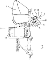
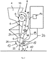
- a planting device 2 according to the invention for root crops is presently designed as a potato planting device, specifically as a cup planting machine. It goes without saying that the invention can also be used in belt laying machines. It has at least one bunker 4 for a multiplicity of separable propagation fruits 6 in the form of potato tubers and a separating device 8 for the individual delivery of the propagation crops 6 to be laid in rows onto an agricultural area 10 ( 1 and 2 ). Furthermore, the laying device 2 has an application device with two nozzles 12 in the present case for dispensing the application agent stored in a tank 13 , in this case a dressing agent. This is sprayed onto the propagation crops 6 by means of the nozzles 12 .
- a control device 14 comprising an EDP unit, which is designed with the usual communication interfaces for controlling and communicating with other functional parts of the laying device 2, in particular for controlling the pumps and valves of the laying device 2 (not shown in detail), is based on at least one signal from a signal transmitter device, which has two propagation fruit sensors 18 in the present case, is designed for automatic control of the application device for the purpose of an intermittent delivery of the dressing.
- the sensors are connected to the control device 14 via data lines 19 .
- control device 14 is able to interpret the data received from the propagating crop sensors 18 so quickly that the nozzles arranged directly below the propagating crop sensor 18 can build up spray fields 22 for wetting the potatoes in good time.
- the signal transmitter device generally includes the sensors 18 and their data lines 19 to the control device.
- the control device 14 receives additional information about the speed at which the potato tubers are conveyed through an output channel in the direction of an output opening via the signal transmitter device due to its coupling to a drive member 16 of the separating device of the cup planter.
- a trajectory 20 results in the direction of the useful surface 10, which is formed by the two nozzles 12 on both sides ( 1 and 2 ) is limited.
- the respective spray fields 22 then form in good time for the potato tuber to be wetted over its entire surface.
- the conveying speed can be reduced or the spray field 22 can be made longer, depending on the nozzle used be fanned out differently and/or the pressure in the application device can be increased.
- the dispensing of the dressing agent via the nozzles 12, which is controlled by the control device 14, can result in each case on the basis of current measured values.
- this delivery can be preset automatically in the control device 14 without using any further sensors.
- the application agent in particular the dressing agent, is transported via fluid lines 26 forming fluid channels from the storage container designed as a tank 13 to the nozzles, the dispensing being effected by opening a valve and/or pressure build-up by means of a pump not shown in detail.
- a valve to be actuated is arranged in the vicinity of the nozzles, interrupting the respective fluid channel 26, while the pump for the application agent is arranged in the vicinity of the tank 13.
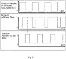
- An exemplary signal processing for a device according to the invention is shown in 3 States changing between “0” and “1” with respect to the y-axis.
- the time is plotted on the x-axes in each case.
- “1” means that the potato is in the sensor detection area
- "0” means that the potato is not in the detection area.
- the middle signal course characterizes with "1” an open position of a nozzle and correspondingly a delivery of an application agent, while "0” means no delivery.
- the period of time for the potato in front of the nozzle, ie in the spray field is shown as "1"
- the period outside of the spray field is shown as "0".
Landscapes
- Life Sciences & Earth Sciences (AREA)
- Soil Sciences (AREA)
- Environmental Sciences (AREA)
- Engineering & Computer Science (AREA)
- Water Supply & Treatment (AREA)
- Fertilizing (AREA)
- Pretreatment Of Seeds And Plants (AREA)
Applications Claiming Priority (2)
| Application Number | Priority Date | Filing Date | Title |
|---|---|---|---|
| DE102021101392 | 2021-01-22 | ||
| DE102021103636.4A DE102021103636A1 (de) | 2021-01-22 | 2021-02-16 | Legevorrichtung für Hackfrüchte sowie Verfahren zum Betreiben einer solchen Legevorrichtung |
Publications (2)
| Publication Number | Publication Date |
|---|---|
| EP4032384A2 true EP4032384A2 (fr) | 2022-07-27 |
| EP4032384A3 EP4032384A3 (fr) | 2022-08-24 |
Family
ID=79927570
Family Applications (1)
| Application Number | Title | Priority Date | Filing Date |
|---|---|---|---|
| EP22152575.1A Pending EP4032384A3 (fr) | 2021-01-22 | 2022-01-20 | Dispositif de pose pour plantes sarclées, ainsi que procédé de fonctionnement d'un tel dispositif de pose |
Country Status (1)
| Country | Link |
|---|---|
| EP (1) | EP4032384A3 (fr) |
Cited By (1)
| Publication number | Priority date | Publication date | Assignee | Title |
|---|---|---|---|---|
| CN118575634A (zh) * | 2024-07-03 | 2024-09-03 | 贵州省山地农业机械研究所 | 一种芋头播种用姿态调整装置 |
Citations (1)
| Publication number | Priority date | Publication date | Assignee | Title |
|---|---|---|---|---|
| DE102018117493A1 (de) | 2018-07-19 | 2020-01-23 | Amazonen-Werke H. Dreyer Gmbh & Co. Kg | Saatgutablageeinrichtung für eine Sämaschine |
Family Cites Families (3)
| Publication number | Priority date | Publication date | Assignee | Title |
|---|---|---|---|---|
| AU2013204455B2 (en) * | 2012-08-20 | 2015-05-21 | Capstan Ag Systems, Inc. | System and method for spraying seeds dispensed from a planter |
| US9730377B2 (en) * | 2015-06-26 | 2017-08-15 | Cnh Industrial Canada, Ltd. | Planter with on-board seed treatment |
| CN109068579A (zh) * | 2016-04-22 | 2018-12-21 | 拜耳作物科学股份公司 | 精密播种机 |
-
2022
- 2022-01-20 EP EP22152575.1A patent/EP4032384A3/fr active Pending
Patent Citations (1)
| Publication number | Priority date | Publication date | Assignee | Title |
|---|---|---|---|---|
| DE102018117493A1 (de) | 2018-07-19 | 2020-01-23 | Amazonen-Werke H. Dreyer Gmbh & Co. Kg | Saatgutablageeinrichtung für eine Sämaschine |
Cited By (1)
| Publication number | Priority date | Publication date | Assignee | Title |
|---|---|---|---|---|
| CN118575634A (zh) * | 2024-07-03 | 2024-09-03 | 贵州省山地农业机械研究所 | 一种芋头播种用姿态调整装置 |
Also Published As
| Publication number | Publication date |
|---|---|
| EP4032384A3 (fr) | 2022-08-24 |
Similar Documents
| Publication | Publication Date | Title |
|---|---|---|
| DE3879446T2 (de) | Geraet zum ausgeben von fluessigkeiten. | |
| DE102007036870B4 (de) | Verstellbare Düsenwinkel | |
| EP3185680B1 (fr) | Pulvérisateur agricole comprenant un système pour le control automatique des profiles de pulvérisation | |
| EP3763551B1 (fr) | Procédé de commande d'une installation de régulation de pression des pneus d'un attelage agricole | |
| EP3248463A1 (fr) | Dispositif de pulvérisation, procédé et module de détection | |
| EP2898773B1 (fr) | Procédé d'épandage contrôlé et/ou régulé de produits phytosanitaires ainsi qu'épandeur agricole pour l'application du procédé | |
| EP3706566A1 (fr) | Procédé pour la commande séquentielle d'unités de buse de pulvérisation | |
| EP0743001A1 (fr) | Dispositif et procédé de pulvérisation de cultures étendus | |
| EP3811778A1 (fr) | Appareil de traitement du sol agricole | |
| EP3539376A1 (fr) | Système de distribution d'un pulvérisateur agricole doté d'un agencement optimisé de buses de distribution et procédé d'épandage de fluides de pulvérisation | |
| EP4032384A2 (fr) | Dispositif de pose pour plantes sarclées, ainsi que procédé de fonctionnement d'un tel dispositif de pose | |
| EP0432673B1 (fr) | Dispositif mobile pour produire des mélanges actifs sur base de l'eau | |
| EP3991555B1 (fr) | Pulvérisateur agricole et dispositif de pulvérisation pour un pulvérisateur agricole | |
| DE102013107445A1 (de) | Landwirtschaftliche Feldspritze | |
| DE102021103636A1 (de) | Legevorrichtung für Hackfrüchte sowie Verfahren zum Betreiben einer solchen Legevorrichtung | |
| EP3501252A1 (fr) | Système de commande et/ou de réglage, véhicule agricole et procédé de commande et/ou de réglage d'un véhicule agricole | |
| DE102018221442A1 (de) | Landwirtschaftliche Spritzvorrichtung mit zumindest einer Spritzdüseneinheit zum Ausbringen eines Spritzmittels auf ein Feld | |
| EP3711481B1 (fr) | Procédé et dispositif pour l'application des liquides sur des plantes | |
| EP3646725B1 (fr) | Dispositif d'épandage agricole et son procédé de fonctionnement | |
| EP4676221A1 (fr) | Dispositif de pulvérisation agricole | |
| EP3643173B1 (fr) | Procédé de distribution du liquide | |
| EP0800758B1 (fr) | Axe d'entraínement d'une moissonneuse | |
| EP4371409B1 (fr) | Procédé d'épandage de produit de pulvérisation sur une surface agricole et dispositif de pulvérisation agricole | |
| DE102005033575A1 (de) | Verfahren und Vorrichtung zum selektiven Ausbringen eines Wirkstoffes | |
| WO2020058026A1 (fr) | Système de pulvérisation pour l'application d'un matériau à pulvériser liquide, véhicule agricole |
Legal Events
| Date | Code | Title | Description |
|---|---|---|---|
| PUAI | Public reference made under article 153(3) epc to a published international application that has entered the european phase |
Free format text: ORIGINAL CODE: 0009012 |
|
| STAA | Information on the status of an ep patent application or granted ep patent |
Free format text: STATUS: THE APPLICATION HAS BEEN PUBLISHED |
|
| PUAL | Search report despatched |
Free format text: ORIGINAL CODE: 0009013 |
|
| AK | Designated contracting states |
Kind code of ref document: A2 Designated state(s): AL AT BE BG CH CY CZ DE DK EE ES FI FR GB GR HR HU IE IS IT LI LT LU LV MC MK MT NL NO PL PT RO RS SE SI SK SM TR |
|
| AK | Designated contracting states |
Kind code of ref document: A3 Designated state(s): AL AT BE BG CH CY CZ DE DK EE ES FI FR GB GR HR HU IE IS IT LI LT LU LV MC MK MT NL NO PL PT RO RS SE SI SK SM TR |
|
| RIC1 | Information provided on ipc code assigned before grant |
Ipc: A01C 7/10 20060101ALI20220715BHEP Ipc: A01C 1/08 20060101ALI20220715BHEP Ipc: A01C 23/00 20060101ALI20220715BHEP Ipc: A01C 7/06 20060101ALI20220715BHEP Ipc: A01C 9/00 20060101AFI20220715BHEP |
|
| STAA | Information on the status of an ep patent application or granted ep patent |
Free format text: STATUS: REQUEST FOR EXAMINATION WAS MADE |
|
| 17P | Request for examination filed |
Effective date: 20230222 |
|
| RBV | Designated contracting states (corrected) |
Designated state(s): AL AT BE BG CH CY CZ DE DK EE ES FI FR GB GR HR HU IE IS IT LI LT LU LV MC MK MT NL NO PL PT RO RS SE SI SK SM TR |
|
| STAA | Information on the status of an ep patent application or granted ep patent |
Free format text: STATUS: EXAMINATION IS IN PROGRESS |
|
| 17Q | First examination report despatched |
Effective date: 20250228 |
|
| RAP3 | Party data changed (applicant data changed or rights of an application transferred) |
Owner name: GRIMME LANDMASCHINENFABRIK SE & CO. KG |