EP4032336B1 - Assistance vis-à-vis d'un mpe dans des systèmes de télécommunications - Google Patents
Assistance vis-à-vis d'un mpe dans des systèmes de télécommunications Download PDFInfo
- Publication number
- EP4032336B1 EP4032336B1 EP20761561.8A EP20761561A EP4032336B1 EP 4032336 B1 EP4032336 B1 EP 4032336B1 EP 20761561 A EP20761561 A EP 20761561A EP 4032336 B1 EP4032336 B1 EP 4032336B1
- Authority
- EP
- European Patent Office
- Prior art keywords
- event
- maximum permissible
- permissible exposure
- report
- mpe
- Prior art date
- Legal status (The legal status is an assumption and is not a legal conclusion. Google has not performed a legal analysis and makes no representation as to the accuracy of the status listed.)
- Active
Links
Images


Classifications
-
- H—ELECTRICITY
- H04—ELECTRIC COMMUNICATION TECHNIQUE
- H04W—WIRELESS COMMUNICATION NETWORKS
- H04W52/00—Power management, e.g. Transmission Power Control [TPC] or power classes
- H04W52/04—Transmission power control [TPC]
- H04W52/18—TPC being performed according to specific parameters
-
- H—ELECTRICITY
- H04—ELECTRIC COMMUNICATION TECHNIQUE
- H04W—WIRELESS COMMUNICATION NETWORKS
- H04W24/00—Supervisory, monitoring or testing arrangements
- H04W24/10—Scheduling measurement reports ; Arrangements for measurement reports
-
- H—ELECTRICITY
- H04—ELECTRIC COMMUNICATION TECHNIQUE
- H04W—WIRELESS COMMUNICATION NETWORKS
- H04W72/00—Local resource management
- H04W72/04—Wireless resource allocation
- H04W72/044—Wireless resource allocation based on the type of the allocated resource
- H04W72/0473—Wireless resource allocation based on the type of the allocated resource the resource being transmission power
Definitions
- the present specification relates to mobile communication systems, in particular to the use of mobile communication systems in accordance with exposure guidelines.
- Exposure guidelines for communication systems are known. Such exposure guidelines may be expressed relative to specific absorption rate (SAR) or maximum permissible exposure (MPE). Although developments have been made, there remains scope for further developments in this field.
- SAR specific absorption rate
- MPE maximum permissible exposure
- US 2012/0178494 describes methods, apparatus and systems for a wireless transmit/receive unit (WTRU) to manage its transmission power.
- a power headroom report (PHR) may be triggered based on changes to backoff or the impacts of backoff. Additional backoff may be used to calculate a maximum output power of the WTRU and may be indicated by a domination indicator to network resources.
- PHR power headroom report
- Prior-art document " Mitigating Radio Link Failures due to MPE on FR2", 3GPP R4-1910278 discusses mechanisms helping the network cope with UE Maximum Permissible Exposure (MPE) limitations.
- MPE Maximum Permissible Exposure
- this specification describes an apparatus (e.g. an user device, or an apparatus implemented at a user device) comprising: means for detecting an occurrence of a maximum permissible exposure event (e.g. when a user device is at a distance less than a minimum safety distance from a user); means for determining a severity of the detected maximum permissible exposure event; means for setting a periodic scheduling override condition to be valid in the event that the detected maximum permissible exposure event is determined to have a high severity; means for reporting (e.g.
- a first timer may be provided for monitoring said first time period (e.g. the first time period may be the period of the first timer).
- the detected maximum permissible exposure event may be determined to have a high severity in the event that a duty cycle reduction required to address said exposure event is above a threshold or in the event that power backoff requirements are above a threshold.
- Some example embodiments further comprise means for monitoring an ongoing maximum permissible exposure event (e.g. using a second timer). Some example embodiments further comprise means for reporting that the maximum permissible exposure event has ended in the event that the maximum permissible exposure event ends before a second time period expires.
- the second time period may be the same, or may be different, to the first time period referred to above.
- Some example embodiments further comprise a first timer for monitoring said first time period.
- the first time period may be the period of the first timer.
- Some example embodiments further comprise a second timer for monitoring the second time period referred to above.
- the second time period may be same as the first time period, but this is not essential to all example embodiments.
- the second time period may be shorter than the first.
- the first and second timers may be implemented using the same timer apparatus, or using separate timer apparatus.
- Some example embodiments further comprise means for indicating (e.g. by communication with the relevant network, base station, node B etc.) that the apparatus (e.g. the relevant user device) is capable of providing maximum permissible exposure assistance information.
- Some example embodiments further comprise means for triggering a power backoff in response to the maximum permissible exposure event.
- some example embodiments further comprise means for triggering a duty cycle adjustment (or a duty cycle limit) in response to the maximum permissible exposure event.
- the power backoff and/or the duty cycle limit may be triggered in order to meet MPE regulation requirements.
- Some example embodiments further comprise means for reconfiguring user device protocols to enable maximum permissible exposure assistance information to be communicated between a user device and a network element.
- the said maximum permissible exposure assistance information may be provided as part of a modified L3-based UE assistance signalling procedure.
- said signalling procedure may include: establishing a connection; exchanging capabilities; and device reconfiguration.
- this specification describes a method comprising: detecting a maximum permissible exposure event report; determining whether the detected maximum permissible exposure report is a scheduled report or an unscheduled report; determining whether one or more time periods of the maximum permissible exposure event protocol should be updated in the event that the detected maximum permissible exposure event report is determined to be an unscheduled report, in order to reduce the instances of unscheduled reports; and adjusting uplink resources to meet maximum permissible exposure power backoff requirements.
- the method may further comprise storing maximum permissible exposure event statistics on receipt of a maximum permissible exposure event report.
- the method may further comprise defining a first timer start time for a user device, wherein said scheduled report is sent by said user device in the event of the expiry of said first timer.
- Example embodiments may further comprise defining first timer start times for each of a plurality of user devices.
- this specification describes an apparatus configured to perform any method as described with reference to the third or fourth aspects.
- this specification describes computer-readable instructions which, when executed by computing apparatus, cause the computing apparatus to perform any method as described with reference to the third or fourth aspects.
- this specification describes a computer readable medium comprising program instructions stored thereon for performing at least the following: detecting a maximum permissible exposure event report; determining whether the detected maximum permissible exposure report is a scheduled report or an unscheduled report; determining whether one or more time periods of the maximum permissible exposure event protocol should be updated in the event that the detected maximum permissible exposure event report is determined to be an unscheduled report, in order to reduce the instances of unscheduled reports; and adjusting uplink resources to meet maximum permissible exposure power backoff requirements.
- this specification describes a computer program comprising instructions which, when the program is executed by a computer, cause the computer to carry out at least the following: detecting an occurrence of a maximum permissible exposure event; and determining a severity of the detected maximum permissible exposure event; setting a periodic scheduling override condition to be valid in the event that the detected maximum permissible exposure event is determined to have a high severity; and reporting maximum permissible exposure assistance information in response to the detection of the occurrence of the maximum permissible exposure event, wherein reporting the maximum permissible exposure assistance information comprises: generating a scheduled report in the event that a periodic scheduling override condition is invalid, wherein the scheduled report is sent when a first time period expires; and generating an unscheduled report in the event that the periodic scheduling override condition is valid, wherein the unscheduled report is sent without waiting for the first time period to expire.
- this specification describes a computer program comprising instructions which, when the program is executed by a computer, cause the computer to carry out at least the following: detecting a maximum permissible exposure event report; determining whether the detected maximum permissible exposure report is a scheduled report or an unscheduled report; determining whether one or more time periods of the maximum permissible exposure event protocol should be updated in the event that the detected maximum permissible exposure event report is determined to be an unscheduled report, in order to reduce the instances of unscheduled reports; and adjusting uplink resources to meet maximum permissible exposure power backoff requirements.
- this specification describes an apparatus comprising: at least one processor; and at least one memory including computer program code which, when executed by the at least one processor, causes the apparatus to: detect an occurrence of a maximum permissible exposure event; and report maximum permissible exposure assistance information in response to the detection of the occurrence of the maximum permissible exposure event, wherein reporting the maximum permissible exposure assistance information comprises: generating a scheduled report in the event that a periodic scheduling override condition is invalid, wherein the scheduled report is sent when a first time period expires; and generating an unscheduled report in the event that the periodic scheduling override condition is valid, wherein the unscheduled report is sent without waiting for the first time period to expire.
- this specification describes an apparatus comprising: at least one processor; and at least one memory including computer program code which, when executed by the at least one processor, causes the apparatus to: detect a maximum permissible exposure event report; determine whether the detected maximum permissible exposure report is a scheduled report or an unscheduled report; determine whether one or more time periods of the maximum permissible exposure event protocol should be updated in the event that the detected maximum permissible exposure event report is determined to be an unscheduled report, in order to reduce the instances of unscheduled reports; and adjust uplink resources to meet maximum permissible exposure power backoff requirements.
- this specification describes an apparatus comprising: a maximum permissible exposure event monitor for detecting an occurrence of a maximum permissible exposure event; and an output for reporting maximum permissible exposure assistance information (e.g. to a network node) in response to the detection of the occurrence of the maximum permissible exposure event, wherein reporting the maximum permissible exposure assistance information comprises: generating a scheduled report in the event that a periodic scheduling override condition is invalid, wherein the scheduled report is sent when a first time period expires; and generating an unscheduled report in the event that the periodic scheduling override condition is valid, wherein the unscheduled report is sent without waiting for the first time period to expire.
- the millimeter-wave (mmW) spectrum offers the possibility of using large portions of contiguous bandwidth to enable mobile communication systems to provide highthroughput applications.
- the 5th Generation (5G) New Radio (NR) frequency spectrum extends well-above the previous 4th Generation (4G) spectrum, which was ranging from 400 MHz to 6 GHz - otherwise known as Frequency Range 1 (FR1).
- Frequency Range 2 (FR2) comprises the frequencies between 24 GHz and 52 GHz; and extending the NR operation into the 52-114 GHz range is currently being discussed.
- millimeter-wave regime specifies and regulates the maximum power for the user equipment (UE). Since frequencies below 100 GHz are non-ionizing, the concern for health is limited to thermal heating of the body tissue while absorbing electromagnetic mmW energy. Millimeter-wave frequencies yield penetration depths below 1 mm, therefore possible thermal damage is limited to the surface of the skin and the eyes; indeed, most of the energy is absorbed within the first 0.4 mm of the human skin at 42 GHz.
- MPE Maximum Permissible Exposure
- the FCC and ICNIRP set the threshold for MPE at 10W/m 2 (1 mW/cm 2 ), for the general public, between 6 or 10 GHz respectively and 100 GHz.
- the energy absorbed by the human body increases as a function of the distance to the UE. Therefore, to comply with the MPE limit, the UE may reduce its output power if the user gets in close vicinity of the antenna.
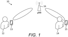
- FIG. 1 is a block diagram of a system, indicated generally by the reference numeral 10, in accordance with an example embodiment.
- a first user 12 is using a first mobile communication device (UE) 13 to communicate with a network node (gNB) 16 and a second user 14 is using a second mobile communication device (UE) 15 to communicate with the network node 16.
- UE mobile communication device
- gNB network node
- UE mobile communication device
- communications between the first device 13 and the network node 16 occur via an unobstructed Line of Sight (LOS) path, whereas the second user 14 stands at least partially in the path of a beam from the second device 15 to the network node 16.
- LOS Line of Sight
- the second user is exposed to a radiated beam between the second device 15 and the network node 16.
- the amount of energy absorbed by the user's body may be relatively large; as such the output power of the second device 15 may need to be reduced to comply with MPE requirements.
- FIG. 2 is a graph, indicated generally by the reference numeral 20, showing maximum allowed equivalent isotropically radiated power (EIRP) depending on the distance between a user device (e.g. an antenna of the user device) and a user. As is clearly shown in the example graph 20, the maximum allowed EIRP reduces as the distance between the user device and the user is reduced.
- EIRP equivalent isotropically radiated power
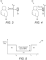
- FIG. 3 is a block diagram of a system 30 in accordance with an example embodiment.
- the system 30 comprises a user 32 (similar to the users 12 and 14 described above) and a user device 34 (similar to the user devices 13 and 15 described above).
- the user 32 and the user device 34 are separated by a distance d user-UE that is greater than a minimum safety distance d min .
- FIG. 4 is a block diagram of a system 40, indicated generally by the reference numeral 40, in accordance with an example embodiment.
- the system 40 comprises the user 32 and the user device 34 described above with reference to FIG. 3 .
- the user 32 and the user device 34 are separated by a distance d user-UE that is less than a minimum safety distance d min .
- the user device 34 When the distance between the user 32 and the user device 34 goes below the minimum safety distance d min , then the user device is required to perform a power back-off in order to meet the MPE regulation requirements. This back-off is referred to herein as an MPE event.
- FIG. 5 is a plot, indicated generally by the reference numeral 50, showing an example power back-off feature.
- the plot shows a user device transmit power (on the y-axis) plotted against time.
- the user device transmit power is reduced between times t 0 and t 1 (due to an MPE event).
- the user device transmit power may be reduced, for example, by reducing a duty cycle of uplink transmissions.
- the network node may be unable to receive enough power from the uplink transmission from the user device in order to decode successfully the transmitted payload from the user device. This may be the case, for example, since the link adaptation (e.g. the selection of MCS, TBS and UL transmission power) may have been performed when the user device was at a position above the d min MPE triggering distance. Depending on the duration of the MPE event, a radio link failure (RLF) might also be triggered, resulting in disruption to a user experience and requiring the user device to reconnect to the relevant network (e.g. transition again to an RRC connected state).
- RLF radio link failure
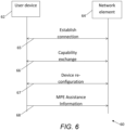
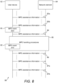
- FIG. 6 is a message sequence, indicated generally by the reference numeral 60, in accordance with an example embodiment.
- the message sequence shows messages between a user device 62 (such as the user device 13, 15 or 34 described above) and a network element 64 (such as the network node 16 described above) that enables the user device 62 to inform the network element 64 of the occurrence of an MPE event.
- the message sequence 60 comprises establish connection messages 65, capability exchange messages 66, device re-configuration messages 67 and MPE assistance information 68.
- the MPE assistance information 68 may be used to report the occurrence of an MPE event.
- the message sequence 60 may be implemented using Radio Resource Control (RRC) protocols, as discussed further below.
- RRC Radio Resource Control
- the message sequence 60 starts with establish connection messages 65 in which the user device 62 establishes a connection with the network element 64.
- the user device 62 may transition from a radio resource control (RRC) idle or inactive state to an RRC connected state.
- RRC radio resource control
- the establish connection messages 65 are followed by capability exchange messages 66 in which the user device 62 informs the network element 64 of its capabilities, typically in response to requests for such information from the network element.
- the user device 62 informs the network element 64 that it is capable of providing MPE related UE assistance as part of the capability exchange messages 66.
- the network element 64 configures the users device 62 to be able to to report the MPE related UE assistance.
- This configuration may include details such as how often the user device 62 is allowed to perform this reporting (e.g. the range of allowable periodicity). For example, a long periodicity may be preferred in order to minimize signaling overhead. Alternatively, a small periodicity may be preferred to enable the network to react quickly (e.g. to adjust power back-off at the user device quickly).
- the re-configuration messages may be in accordance with existing RRC reconfiguration protocols.
- the user device 62 upon detecting the occurrence of an MPE event, transmits to the network its MPE Assistance Information as part of the MPE assistance information message 68.
- the transmission of the MPE event report timing may depends on the severity of the MPE conditions.
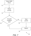
- FIG. 7 is a flow chart showing an algorithm, indicated generally by the reference numeral 70, in accordance with an example embodiment.
- the algorithm 70 starts at operation 72, where the occurrence of a maximum permissible exposure (MPE) event is detected.
- MPE maximum permissible exposure
- operation 76 determines that the override condition is not met (e.g. if the severity of the MPE event is below a threshold level)
- the algorithm 70 moves to a wait state 78.
- an MPE report (referred to below as a scheduled MPE report) is generated at operation 79.
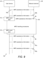
- the message sequence 90 shows the detection of an MPE event 91 at the user device 62 and the detection of the end of an MPE event 92 at the user device.
- the message sequence 90 shows how this information is communicated to the network element 64 in the event that the override condition of operation 76 of the algorithm 70 is met (e.g. the MPE event is considered to be severe).
- a second timer T2 is set.
- the first timer T1 and the second timer T2 may have the same duration or different durations; for example, the second timer duration may be shorter than the first.
- the timers may be two instances of the same timer or may be separate timers.
- the end of the MPE event is reported (e.g. by the user device 62 to the network element 64).
- the operation 111 may be implemented, for example, by the message 86 of the message sequence 80 or the message 96 of the message sequence 90 described above.
- Example implementations of the operation 112 include considering a duty cycle threshold, a power back-off threshold or a flag.
- the overriding condition in operation 112 may be the same as the condition in operation 105, but this is not essential.
- the overriding condition in operation 112 may be stricter than the condition in operation 105 or stricter than the actual condition of the user device at that time, thereby determining whether or not the MPE event is getting worse (e.g. is the user device 62 moving closer to the user).
- FIG. 11 is a flow chart showing an algorithm, indicated generally by the reference numeral 120, in accordance with an example embodiment.
- the algorithm 120 is initiated at operation 121.
- the algorithm 120 may be implemented at the network element 64 (or some similar node).
- information is extracted (e.g. at the network element 64) about the user device triggering the unscheduled report and this information is used to create statistics.
- MPE event statistics may be generated and stored on receipt of an MPE event report.
- one or more time periods (e.g. timers) of the MPE event protocol may be updated, in order to reduce the instances of unscheduled reports.
- the timers (or time periods) may be updated using machine learning algorithms.
- the values associated with the first and/or the second timers described above may be adjusted. It should be noted that, in certain cells (or even for individual users), the occurrence of MPE events will be different. For example, a specific user might regularly hold the user deice close to their head in a talk mode, while another one might consistently use a headset with the user device placed on a surface away from the user. In the latter case it is expected that fewer MPE events will occur and as such the T1 and T2 timers can be more relaxed.
- information is extracted (e.g. at the network element 64) about the user device triggering the scheduled report and this information is used to create statistics.
- MPE event statistics may be generated and stored on receipt of an MPE event report.
- the uplink resources of the user device 62 are adjusted, for example to meet the MPE power back-off requirements.
- an uplink duty cycle may be modified in the operation 127.
- the uplink resources may also be modified by defining a first timer start time for a particular user device, wherein said scheduled report is sent by said user device to said apparatus in the event of the expiry of said first timer.
- the first timer start time may be set to be different for different user devices, such that the first timers (and hence the scheduled reports) are staggered.
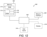
- FIG. 12 is an example schematic diagram of components of one or more of the modules for implementing the algorithms described above, which hereafter are referred to generically as processing systems 300.
- a processing system 300 may have a processor 302, a memory 304 coupled to the processor and comprised of a RAM 314 and ROM 312, and, optionally, user inputs 310 and a display 318.
- the processing system 300 may comprise one or more network interfaces 308 for connection to a network, e.g. a modem which may be wired or wireless.
- the processor 302 is connected to each of the other components in order to control operation thereof.
- the memory 304 may comprise a non-volatile memory, a hard disk drive (HDD) or a solid state drive (SSD).
- the ROM 312 of the memory 304 stores, amongst other things, an operating system 315 and may store software applications 316.
- the RAM 314 of the memory 304 is used by the processor 302 for the temporary storage of data.
- the operating system 315 may contain code which, when executed by the processor, implements aspects of the algorithms and message sequences 60, 70, 80, 90, 100 and 120.
- the processor 302 may take any suitable form. For instance, it may be a microcontroller, plural microcontrollers, a processor, or plural processors. Processor 302 may comprise processor circuitry.
- the processing system 300 may be a standalone computer, a server, a console, or a network thereof.
- the processing system 300 may also be associated with external software applications. These may be applications stored on a remote server device and may run partly or exclusively on the remote server device. These applications may be termed cloud-hosted applications.
- the processing system 300 may be in communication with the remote server device in order to utilize the software application stored there.
- FIG. 13A and FIG. 13B show tangible media, respectively a removable memory unit 365 and a compact disc (CD) 368, storing computer-readable code which when run by a computer may perform methods according to example embodiments described above.
- the removable memory unit 365 may be a memory stick, e.g. a USB memory stick, having internal memory 366 storing the computer-readable code.
- the memory 366 may be accessed by a computer system via a connector 367.
- the CD 368 may be a CD-ROM or a DVD or similar. Other forms of tangible storage media may be used.
- Some example embodiments of the present invention may be implemented in software, hardware, application logic or a combination of software, hardware and application logic.
- the software, application logic and/or hardware may reside on memory, or any computer media.
- the application logic, software or an instruction set is maintained on any one of various conventional computer-readable media.
- a "memory" or “computer-readable medium” may be any non-transitory media or means that can contain, store, communicate, propagate or transport the instructions for use by or in connection with an instruction execution system, apparatus, or device, such as a computer.
- references to, where relevant, "computer-readable storage medium”, “computer program product”, “tangibly embodied computer program” etc., or a “processor” or “processing circuitry” etc. should be understood to encompass not only computers having differing architectures such as single/multi-processor architectures and sequencers/parallel architectures, but also specialised circuits such as field programmable gate arrays FPGA, application specify circuits ASIC, signal processing devices and other devices.
- References to computer program, instructions, code etc. should be understood to express software for a programmable processor firmware such as the programmable content of a hardware device as instructions for a processor or configured or configuration settings for a fixed function device, gate array, programmable logic device, etc.
- circuitry refers to all of the following: (a) hardware-only circuit implementations (such as implementations in only analogue and/or digital circuitry) and (b) to combinations of circuits and software (and/or firmware), such as (as applicable): (i) to a combination of processor(s) or (ii) to portions of processor(s)/software (including digital signal processor(s)), software, and memory(ies) that work together to cause an apparatus, such as a server, to perform various functions) and (c) to circuits, such as a microprocessor(s) or a portion of a microprocessor(s), that require software or firmware for operation, even if the software or firmware is not physically present.
- Example embodiments described herein may be implemented as part of an existing RRC protocol (such as the specification TS38.311: Radio Resource Control protocol specification).
- the UE shall:
- the purpose of this procedure is to inform the network of the UE's delay budget report carrying desired increment/decrement in the Uu air interface delay, connected mode DRX cycle length, overheating assistance information or MPE assistance information.
- a UE capable of providing delay budget report in RRC_CONNECTED may initiate the procedure in several cases, including upon being configured to provide delay budget report and upon change of delay budget preference.
- a UE capable of providing overheating assistance information in RRC _CONNECTED may initiate the procedure if it was configured to do so, upon detecting internal overheating, or upon detecting that it is no longer experiencing an overheating condition.
- a UE capable of providing MPE assistance information in RRC CONNECTED may initiate the procedure if it was configured to do so, upon detecting the MPE event (i.e. that the UE is below the dmin distance towards the user), or upon detecting that it is no longer experiencing an MPE event.
- the UE Upon initiating the procedure, the UE shall:
- the UE shall set the contents of the UEAssistanceInformation message for the MPE event report as follows:
- the UEAssistanceInformation message is used for the indication of UE assistance information to the network.
- delayBudgetReport Indicates the UE-preferred adjustment to connected mode DRX.
- reducedBW-FR1-DL Indicates the UE's preference on reduced configuration corresponding to the maximum aggregated bandwidth across all downlink carriers of FRt indicated by the field, to address overheating. This field is allowed to be reported only when UE is configured with serving cells operating on FR1.
- reducedBW-FR1-UL Indicates the UE's preference on reduced configuration corresponding to the maximum aggregated bandwidth across all uplink carriers of FR1 indicated by the field, to address overheating. This field is allowed to be reported only when UE is configured with serving cells operating on FR1.
- reducedBW-FR2-DL Indicates the UE's preference on reduced configuration corresponding to the maximum aggregated bandwidth across all downlink carriers of FR2 indicated by the field, to address overheating. This field is allowed to be reported only when UE is configured with serving cells operating on FR2. Value mhzo is only applicable for FR2.
- reducedBW-FR2-UL Indicates the UE's preference on reduced configuration corresponding to the maximum aggregated bandwidth across all uplink carriers of FR2 indicated by the field, to address overheating. This field is allowed to be reported only when UE is configured with serving cells operating on FR2. Value mhzo is only applicable for FR2.
- reducedCCsDL Indicates the UE's preference on reduced configuration corresponding to the maximum number of downlink SCells indicated by the field, to address overheating.
- reducedCCsUL Indicates the UE's preference on reduced configuration corresponding to the maximum number of uplink SCells indicated by the field, to address overheating.
- reducedMIMO-LayersFR1-DL Indicates the UE's preference on reduced configuration corresponding to the maximum number of downlink MIMO layers of each serving cell operating on FR1 indicated by the field, to address overheating. This field is allowed to be reported only when UE is configured with serving cells operating on FR1.
- reducedMIMO-LayersFR1-UL Indicates the UE's preference on reduced configuration corresponding to the maximum number of uplink MIMO layers of each serving cell operating on FR1 indicated by the field, to address overheating. This field is allowed to be reported only when UE is configured with serving cells operating on FR1.
- reducedMIMO-LayersFR2-DL Indicates the UE's preference on reduced configuration corresponding to the maximum number of downlink MIMO layers of each serving cell operating on FR2 indicated by the field, to address overheating. This field is allowed to be reported only when UE is configured with serving cells operating on FR2.
- reducedMIMO-LayersFR2-UL Indicates the UE's preference on reduced configuration corresponding to the maximum number of uplink MIMO layers of each serving cell operating on FR2 indicated by the field, to address overheating. This field is allowed to be reported only when UE is configured with serving cells operating on FR2.
- typei Indicates the preferred amount of increment/decrement to the long DRX cycle length with respect to the current configuration. Value in number of milliseconds.
- ms40 corresponds to 40 milliseconds
- msMinus40 corresponds to -40 milliseconds and so on.
- ueReducedDutyCycle Indicates what is the UE preferred UL transmissions duty cycle reduction.
- dutyCycle0.1 corresponds to a duty cycle of 10%.
- uePowerBackoffRequired Indicates what is the UE preferred UL power backoff. The reported values are in the dB.
- UE-NR-Capability is used to convey the NR UE Radio Access Capability Parameters, see TS 38.306 [26].
- UE-NR-Capability field descriptions featureSetCombinations A list of FeatureSetCombination:s for NR (not for MR-DC). The FeatureSetDownlink:s and FeatureSetUplink:s referred to from these FeatureSetCombination:s are defined in the featureSets list in UE-NR-Capability.
- the IE OtherConfig contains configuration related to miscellaneous other configurations.
- OtherConfig field descriptions delayBudgetReportingProhibitTimer Prohibit timer for delay budget reporting. Value in seconds. Value so means prohibit timer is set to 0 seconds, value sodot4 means prohibit timer is set to 0.4 seconds, and so on.
- overheatingAssistanceConfig Configuration for the UE to report assistance information to inform the gNB about UE detected internal overheating.
- overheatingIndicationProhibitTimer Prohibit timer for overheating assistance information reporting Value in seconds. Value so means prohibit timer is set to 0 seconds, value sodot5 means prohibit timer is set to 0.5 seconds, value s1 means prohibit timer is set to 1 second and so on.
- MIPEAssistanceConfig Configuration for the UE to report assistance information to inform the gNB about UE detected MPE event.
- mpeIndicationProhibitTimerOverride Allows the UE to overrived the configured prohibit timers in case the power backoff due to the duty cycle cannot be met within the remaining timer.
- mpeIndicationProhibitTimer1 Prohibit timer for the MPE assistance information reporting for UEs not experiencing an MPE event. Value in seconds. Value so means prohibit timer is set to o seconds, value sodot5 means prohibit timer is set to 0.5 seconds, and so on.
Landscapes
- Engineering & Computer Science (AREA)
- Computer Networks & Wireless Communication (AREA)
- Signal Processing (AREA)
- Mobile Radio Communication Systems (AREA)
Claims (15)
- Appareil comprenant :des moyens pour détecter (72, 104) l'occurrence d'un cas d'exposition maximale admissible ;des moyens pour déterminer (74) la gravité du cas d'exposition maximale admissible détecté ;des moyens pour fixer une condition de priorité de planification périodique qui sera valide dans le cas où le cas d'exposition maximale admissible détecté est déterminé comme ayant une gravité élevée ; etdes moyens pour signaler (79) des informations d'assistance d'exposition maximale admissible en réponse à la détection de l'occurrence du cas d'exposition maximale admissible, dans lequel les moyens pour signaler les informations d'assistance d'exposition maximale admissible sont configurés pour :générer un rapport planifié dans le cas où la condition de priorité de planification périodique n'est pas valide, dans lequel le rapport planifié est envoyé à l'expiration d'une première période de temps ; etgénérer un rapport non planifié dans le cas où la condition de priorité de planification périodique est valide, dans lequel le rapport non planifié est envoyé sans attendre l'expiration de la première période de temps.
- Appareil selon la revendication 1, dans lequel le cas d'exposition maximale admissible détecté est déterminé comme ayant une gravité élevée dans le cas où une réduction de rapport cyclique nécessaire pour traiter ledit cas d'exposition est au-dessus d'un seuil.
- Appareil selon la revendication 1 ou la revendication 2, comprenant en outre des moyens pour surveiller (109) un cas d'exposition maximale admissible en cours, et facultativement, comprenant en outre des moyens pour signaler (111) que le cas d'exposition maximale admissible a pris fin dans le cas où le cas d'exposition maximale admissible prend fin avant l'expiration d'une deuxième période de temps.
- Appareil selon l'une quelconque des revendications précédentes, comprenant en outre un premier temporisateur pour surveiller ladite première période de temps.
- Appareil selon l'une quelconque des revendications précédentes, comprenant en outre au moins l'un des moyens suivants :des moyens pour indiquer que l'appareil est en mesure de fournir des informations d'assistance d'exposition maximale admissible ;des moyens pour déclencher un recul de puissance en réponse au cas d'exposition maximale admissible ; etdes moyens pour déclencher un réglage de rapport cyclique en réponse au cas d'exposition maximale admissible.
- Appareil comprenant :des moyens pour détecter (123) un rapport de cas d'exposition maximale admissible ;des moyens pour déterminer (124) si le rapport d'exposition maximale admissible détecté est un rapport planifié ou un rapport non planifié ;des moyens pour déterminer (125) si une ou plusieurs périodes de temps d'un protocole de cas d'exposition maximale admissible doivent être mises à jour dans le cas où le rapport de cas d'exposition maximale admissible détecté est déterminé comme étant un rapport non planifié, afin de réduire les instances des rapports non planifiés ; etdes moyens pour régler (127) des ressources de liaison montante pour répondre aux exigences de recul de puissance d'exposition maximale admissible.
- Appareil selon la revendication 6, comprenant en outre des moyens pour stocker des statistiques de cas d'exposition maximale admissible à la réception d'un rapport de cas d'exposition maximale admissible.
- Appareil selon la revendication 6 ou la revendication 7, comprenant en outre des moyens pour recevoir une indication selon laquelle un dispositif utilisateur à distance est en mesure de fournir des informations d'assistance relatives à l'exposition maximale admissible.
- Appareil selon l'une quelconque des revendications 6 à 8, comprenant en outre des moyens pour définir une première heure de début de temporisateur pour un dispositif utilisateur, dans lequel ledit rapport planifié est envoyé par ledit dispositif utilisateur audit appareil en cas d'expiration dudit premier temporisateur, dans lequel les moyens pour définir une première heure de début de temporisateur définissent facultativement des premières heures de début de temporisateur pour chacun d'une pluralité de dispositifs utilisateurs.
- Appareil selon l'une quelconque des revendications précédentes, comprenant en outre des moyens pour reconfigurer des protocoles de dispositif utilisateur afin de permettre la communication d'informations d'assistance d'exposition maximale admissible entre un dispositif utilisateur et un élément de réseau.
- Appareil selon la revendication 10, dans lequel lesdites informations d'assistance d'exposition maximale admissible sont fournies dans le cadre d'une procédure de signalisation d'assistance à l'UE basée sur L3 modifiée.
- Procédé comprenant les étapes suivantes :détecter (72, 104) l'occurrence d'un cas d'exposition maximale admissible ;déterminer (74) la gravité du cas d'exposition maximale admissible détecté et fixer une condition de priorité de planification périodique qui sera valide dans le cas où le cas d'exposition maximale admissible détecté est déterminé comme ayant une gravité élevée ; etsignaler (79) des informations d'assistance d'exposition maximale admissible en réponse à la détection de l'occurrence du cas d'exposition maximale admissible,dans lequel le signalement des informations d'assistance d'exposition maximale admissible comprend : la génération d'un rapport planifié dans le cas où la condition de priorité de planification périodique n'est pas valide, dans lequel le rapport planifié est envoyé à l'expiration d'une première période de temps ; et la génération d'un rapport non planifié dans le cas où la condition de priorité de planification périodique est valide, dans lequel le rapport non planifié est envoyé sans attendre l'expiration de la première période de temps.
- Procédé comprenant les étapes suivantes :détecter (123) un rapport de cas d'exposition maximale admissible ;déterminer (124) si le rapport d'exposition maximale admissible détecté est un rapport planifié ou un rapport non planifié ;déterminer (125) si une ou plusieurs périodes de temps d'un protocole de cas d'exposition maximale admissible doivent être mises à jour dans le cas où le rapport de cas d'exposition maximale admissible détecté est déterminé comme étant un rapport non planifié, afin de réduire les instances des rapports non planifiés ; etrégler (127) des ressources de liaison montante pour répondre aux exigences de recul de puissance d'exposition maximale admissible.
- Programme informatique comprenant des instructions qui, lorsque le programme est exécuté par un ordinateur, amènent l'ordinateur à effectuer au moins ce qui suit :détecter l'occurrence d'un cas d'exposition maximale admissible ; etdéterminer la gravité du cas d'exposition maximale admissible détecté ;fixer une condition de priorité de planification périodique qui sera valide dans le cas où le cas d'exposition maximale admissible détecté est déterminé comme ayant une gravité élevée ; etsignaler des informations d'assistance d'exposition maximale admissible en réponse à la détection de l'occurrence du cas d'exposition maximale admissible,dans lequel le signalement des informations d'assistance d'exposition maximale admissible comprend : la génération d'un rapport planifié dans le cas où la condition de priorité de planification périodique n'est pas valide, dans lequel le rapport planifié est envoyé à l'écoulement d'une première période de temps ; et la génération d'un rapport non planifié dans le cas où la condition de priorité de planification périodique est valide, dans lequel le rapport non planifié est envoyé sans attendre l'expiration de la première période de temps.
- Programme informatique comprenant des instructions qui, lorsque le programme est exécuté par un ordinateur, amènent l'ordinateur à effectuer au moins ce qui suit :détecter un rapport de cas d'exposition maximale admissible ;déterminer si le rapport d'exposition maximale admissible détecté est un rapport planifié ou un rapport non planifié ;déterminer si une ou plusieurs périodes de temps d'un protocole de cas d'exposition maximale admissible doivent être mises à jour dans le cas où le rapport de cas d'exposition maximale admissible détecté est déterminé comme étant un rapport non planifié, afin de réduire les instances des rapports non planifiés ; etrégler des ressources de liaison montante pour répondre aux exigences de recul de puissance d'exposition maximale admissible.
Applications Claiming Priority (2)
| Application Number | Priority Date | Filing Date | Title |
|---|---|---|---|
| GB201913562A GB201913562D0 (en) | 2019-09-20 | 2019-09-20 | MPE Assistance in telecommunication systems |
| PCT/EP2020/073624 WO2021052716A1 (fr) | 2019-09-20 | 2020-08-24 | Assistance vis-à-vis d'un mpe dans des systèmes de télécommunications |
Publications (3)
| Publication Number | Publication Date |
|---|---|
| EP4032336A1 EP4032336A1 (fr) | 2022-07-27 |
| EP4032336B1 true EP4032336B1 (fr) | 2025-01-08 |
| EP4032336C0 EP4032336C0 (fr) | 2025-01-08 |
Family
ID=68425574
Family Applications (1)
| Application Number | Title | Priority Date | Filing Date |
|---|---|---|---|
| EP20761561.8A Active EP4032336B1 (fr) | 2019-09-20 | 2020-08-24 | Assistance vis-à-vis d'un mpe dans des systèmes de télécommunications |
Country Status (5)
| Country | Link |
|---|---|
| US (1) | US20230031232A1 (fr) |
| EP (1) | EP4032336B1 (fr) |
| CN (1) | CN114430925B (fr) |
| GB (1) | GB201913562D0 (fr) |
| WO (1) | WO2021052716A1 (fr) |
Families Citing this family (11)
| Publication number | Priority date | Publication date | Assignee | Title |
|---|---|---|---|---|
| EP3767325B1 (fr) * | 2019-07-19 | 2026-01-07 | Aptiv Technologies AG | Procédés et systèmes de traitement de réflexions radar |
| CN112584374B (zh) * | 2019-09-27 | 2022-03-25 | 维沃移动通信有限公司 | 能力参数确定方法、上行调度方法、终端和网络侧设备 |
| US12392881B2 (en) * | 2020-02-05 | 2025-08-19 | Samsung Electronics Co., Ltd. | System and method for detecting proximity of users |
| WO2021168642A1 (fr) * | 2020-02-25 | 2021-09-02 | Qualcomm Incorporated | Techniques de détection d'événements d'exposition maximale admissible (mpe) dans des communications sans fil |
| ES2992103T3 (es) | 2020-05-13 | 2024-12-09 | Nokia Technologies Oy | Gestión de portadoras en una red de comunicación inalámbrica |
| WO2022129695A1 (fr) | 2020-12-18 | 2022-06-23 | Nokia Technologies Oy | Configuration de faisceau radio |
| US20240162969A1 (en) * | 2021-03-18 | 2024-05-16 | Toyota Jidosha Kabushiki Kaisha | Apparatus and methods for enhancing multi-beam operation in wireless networks |
| EP4315934A1 (fr) * | 2021-03-30 | 2024-02-07 | Nokia Technologies Oy | Commande d'optimisation de mobilité |
| WO2022252141A1 (fr) * | 2021-06-02 | 2022-12-08 | Qualcomm Incorporated | Rapport différentiel pour valeurs d'exposition maximales admissibles |
| US12494822B2 (en) * | 2021-10-12 | 2025-12-09 | Qualcomm Incorporated | Uplink (UL) beam reset after maximum permissible exposure (MPE) report |
| CN118042580A (zh) * | 2022-11-03 | 2024-05-14 | 维沃移动通信有限公司 | Ue辅助信息上报的触发方法、装置及用户设备 |
Citations (1)
| Publication number | Priority date | Publication date | Assignee | Title |
|---|---|---|---|---|
| US20140153661A1 (en) * | 2012-04-06 | 2014-06-05 | Bertrand Martyn Hochwald | Method of Coding Using Multiple Transmit Chains for Reduced Exposure to Electromagnetic Radiation |
Family Cites Families (15)
| Publication number | Priority date | Publication date | Assignee | Title |
|---|---|---|---|---|
| US5524275A (en) * | 1993-12-17 | 1996-06-04 | Ericsson Ge Mobile Communications Inc. | Averaged RF exposure control |
| WO2003014936A1 (fr) * | 2001-08-06 | 2003-02-20 | Eg Innovations Pte. Ltd. | Procede permettant de fournir a une pluralite d'utilisateurs un controle en temps reel d'elements d'un reseau de donnees |
| US9155049B2 (en) * | 2009-08-17 | 2015-10-06 | Nokia Solutions And Networks Oy | Method and apparatus for power reduction control in home network environment |
| US8577360B2 (en) * | 2010-04-12 | 2013-11-05 | Telefonaktiebolaget Lm Ericsson (Publ) | UE-based MDT measuring and reporting in a cellular radio access network |
| EP3214875B1 (fr) * | 2011-01-07 | 2020-10-07 | InterDigital Patent Holdings, Inc. | Procédés, appareils et systèmes de gestion de recul de puissance additionnel |
| US9681401B2 (en) * | 2011-03-17 | 2017-06-13 | Google Technology Holdings LLC | Enhanced power headroom reporting in wireless communication networks |
| US9025462B2 (en) * | 2012-01-16 | 2015-05-05 | Qualcomm Incorporated | Reception report aggregation |
| US10893488B2 (en) * | 2013-06-14 | 2021-01-12 | Microsoft Technology Licensing, Llc | Radio frequency (RF) power back-off optimization for specific absorption rate (SAR) compliance |
| CN104703237A (zh) * | 2013-12-10 | 2015-06-10 | 中兴通讯股份有限公司 | 实现用户设备软切换的方法及无线网络控制器 |
| US11368926B2 (en) * | 2016-12-12 | 2022-06-21 | Qualcomm Incorporated | Reporting power limit and corresponding constraint |
| CN111148263B (zh) * | 2017-05-05 | 2021-04-09 | 华为技术有限公司 | 发送数据的方法及其装置 |
| US11240766B2 (en) * | 2018-02-16 | 2022-02-01 | Qualcomm Incorporated | Mitigation of maximum permissible exposure (MPE) constraint based on user equipment (UE) feedbacks |
| US12069584B2 (en) * | 2019-07-18 | 2024-08-20 | Nokia Technologies Oy | Power exposure reporting for wireless networks |
| KR20220044588A (ko) * | 2019-09-12 | 2022-04-08 | 애플 인크. | 최대 허용 노출을 위한 빔 관리 솔루션 |
| US20220256472A1 (en) * | 2019-09-12 | 2022-08-11 | Hewlett-Packard Development Company, L.P. | Parameter adjustments of computing devices |
-
2019
- 2019-09-20 GB GB201913562A patent/GB201913562D0/en not_active Ceased
-
2020
- 2020-08-24 US US17/762,291 patent/US20230031232A1/en active Pending
- 2020-08-24 WO PCT/EP2020/073624 patent/WO2021052716A1/fr not_active Ceased
- 2020-08-24 EP EP20761561.8A patent/EP4032336B1/fr active Active
- 2020-08-24 CN CN202080065910.1A patent/CN114430925B/zh active Active
Patent Citations (1)
| Publication number | Priority date | Publication date | Assignee | Title |
|---|---|---|---|---|
| US20140153661A1 (en) * | 2012-04-06 | 2014-06-05 | Bertrand Martyn Hochwald | Method of Coding Using Multiple Transmit Chains for Reduced Exposure to Electromagnetic Radiation |
Non-Patent Citations (1)
| Title |
|---|
| NOKIA ET AL: "Mitigating Radio Link Failures due to MPE on FR2", vol. RAN WG4, no. Ljubljana, Slovenia; 20190826 - 20190830, 16 August 2019 (2019-08-16), XP051771761, Retrieved from the Internet <URL:http://www.3gpp.org/ftp/tsg_ran/WG4_Radio/TSGR4_92/Docs/R4-1908820.zip> [retrieved on 20190816] * |
Also Published As
| Publication number | Publication date |
|---|---|
| WO2021052716A1 (fr) | 2021-03-25 |
| CN114430925A (zh) | 2022-05-03 |
| US20230031232A1 (en) | 2023-02-02 |
| CN114430925B (zh) | 2025-09-16 |
| EP4032336C0 (fr) | 2025-01-08 |
| GB201913562D0 (en) | 2019-11-06 |
| EP4032336A1 (fr) | 2022-07-27 |
Similar Documents
| Publication | Publication Date | Title |
|---|---|---|
| EP4032336B1 (fr) | Assistance vis-à-vis d'un mpe dans des systèmes de télécommunications | |
| EP4017144B1 (fr) | Procédé et dispositif de transmission d'informations, procédé et dispositif de réception d'informations, noeud de communication et support d'enregistrement | |
| US12069584B2 (en) | Power exposure reporting for wireless networks | |
| US11116013B2 (en) | Performing random access procedure via uplink (UL) component carriers in 5G new radio (NR) | |
| EP3791671B1 (fr) | Procédé et système de communication sans fil permettant de gérer un fonctionnement d'une minuterie | |
| CN113647170B (zh) | 用于快速服务小区激活的方法和装置 | |
| EP3918855B1 (fr) | Gestion d'états de cellule de desserte | |
| US20180302914A1 (en) | Methods and Apparatus for Managing Small Data Transmissions from User Equipments, for Managing Radio Resource Control States of User Equipments, and for Managing a Radio Resource Control Context and State of User Equipments | |
| EP3565325B1 (fr) | Procédé d'ajustement de la puissance d'un terminal, et terminal | |
| EP4238363B1 (fr) | Prioriisation de budget de liaison montante (ul) d'exposition maximale autorisée (mpe) pour canal de commande de liaison montante physique (pucch) et canal partagé de liaison montante physique (pusch) | |
| US20230361835A1 (en) | Beam information reporting and receiving method and apparatus | |
| EP3051884B1 (fr) | Procédé et dispositif de commande de puissance de liaison montante | |
| EP3614739B1 (fr) | Procédé de commutation de porteuse de liaison montante, dispositif réseau et dispositif terminal | |
| CN116171586B (zh) | Ul间隙触发 | |
| US11129052B2 (en) | Radio network node, wireless device and methods performed therein | |
| US20230156814A1 (en) | Method for setting data transmission type and terminal | |
| CN114270955B (zh) | 通信方法及装置 | |
| EP4154578B1 (fr) | Échange d'informations relatives à une exposition maximale autorisée pendant un transfert intercellulaire | |
| US20230232334A1 (en) | Carrier management in a wireless communication network | |
| US20210282096A1 (en) | Predictive back-off reporting in telecommunication systems | |
| WO2015192299A1 (fr) | Procédé et appareil d'attribution d'une ressource temps-fréquence | |
| US12160828B2 (en) | Discontinuous reception processing method, and terminal device | |
| EP4243483A1 (fr) | Procédé et dispositif d'ajustement de mesure de ressource, terminal et support d'enregistrement lisible | |
| CN113630858B (zh) | 功率管理报告 | |
| EP4150833A1 (fr) | Mécanisme de déclenchement et de rapport pour un changement de scs |
Legal Events
| Date | Code | Title | Description |
|---|---|---|---|
| STAA | Information on the status of an ep patent application or granted ep patent |
Free format text: STATUS: UNKNOWN |
|
| STAA | Information on the status of an ep patent application or granted ep patent |
Free format text: STATUS: THE INTERNATIONAL PUBLICATION HAS BEEN MADE |
|
| PUAI | Public reference made under article 153(3) epc to a published international application that has entered the european phase |
Free format text: ORIGINAL CODE: 0009012 |
|
| STAA | Information on the status of an ep patent application or granted ep patent |
Free format text: STATUS: REQUEST FOR EXAMINATION WAS MADE |
|
| 17P | Request for examination filed |
Effective date: 20220420 |
|
| AK | Designated contracting states |
Kind code of ref document: A1 Designated state(s): AL AT BE BG CH CY CZ DE DK EE ES FI FR GB GR HR HU IE IS IT LI LT LU LV MC MK MT NL NO PL PT RO RS SE SI SK SM TR |
|
| DAV | Request for validation of the european patent (deleted) | ||
| DAX | Request for extension of the european patent (deleted) | ||
| GRAP | Despatch of communication of intention to grant a patent |
Free format text: ORIGINAL CODE: EPIDOSNIGR1 |
|
| STAA | Information on the status of an ep patent application or granted ep patent |
Free format text: STATUS: GRANT OF PATENT IS INTENDED |
|
| RIC1 | Information provided on ipc code assigned before grant |
Ipc: H04W 72/044 20230101ALN20240415BHEP Ipc: H04W 24/10 20090101AFI20240415BHEP |
|
| INTG | Intention to grant announced |
Effective date: 20240502 |
|
| GRAJ | Information related to disapproval of communication of intention to grant by the applicant or resumption of examination proceedings by the epo deleted |
Free format text: ORIGINAL CODE: EPIDOSDIGR1 |
|
| STAA | Information on the status of an ep patent application or granted ep patent |
Free format text: STATUS: REQUEST FOR EXAMINATION WAS MADE |
|
| GRAP | Despatch of communication of intention to grant a patent |
Free format text: ORIGINAL CODE: EPIDOSNIGR1 |
|
| STAA | Information on the status of an ep patent application or granted ep patent |
Free format text: STATUS: GRANT OF PATENT IS INTENDED |
|
| INTC | Intention to grant announced (deleted) | ||
| RIC1 | Information provided on ipc code assigned before grant |
Ipc: H04W 72/044 20230101ALN20240827BHEP Ipc: H04W 24/10 20090101AFI20240827BHEP |
|
| INTG | Intention to grant announced |
Effective date: 20240906 |
|
| GRAS | Grant fee paid |
Free format text: ORIGINAL CODE: EPIDOSNIGR3 |
|
| GRAA | (expected) grant |
Free format text: ORIGINAL CODE: 0009210 |
|
| STAA | Information on the status of an ep patent application or granted ep patent |
Free format text: STATUS: THE PATENT HAS BEEN GRANTED |
|
| AK | Designated contracting states |
Kind code of ref document: B1 Designated state(s): AL AT BE BG CH CY CZ DE DK EE ES FI FR GB GR HR HU IE IS IT LI LT LU LV MC MK MT NL NO PL PT RO RS SE SI SK SM TR |
|
| REG | Reference to a national code |
Ref country code: GB Ref legal event code: FG4D |
|
| REG | Reference to a national code |
Ref country code: CH Ref legal event code: EP |
|
| REG | Reference to a national code |
Ref country code: DE Ref legal event code: R096 Ref document number: 602020044529 Country of ref document: DE |
|
| REG | Reference to a national code |
Ref country code: IE Ref legal event code: FG4D |
|
| U01 | Request for unitary effect filed |
Effective date: 20250129 |
|
| U07 | Unitary effect registered |
Designated state(s): AT BE BG DE DK EE FI FR IT LT LU LV MT NL PT RO SE SI Effective date: 20250204 |
|
| PG25 | Lapsed in a contracting state [announced via postgrant information from national office to epo] |
Ref country code: RS Free format text: LAPSE BECAUSE OF FAILURE TO SUBMIT A TRANSLATION OF THE DESCRIPTION OR TO PAY THE FEE WITHIN THE PRESCRIBED TIME-LIMIT Effective date: 20250408 |
|
| PG25 | Lapsed in a contracting state [announced via postgrant information from national office to epo] |
Ref country code: PL Free format text: LAPSE BECAUSE OF FAILURE TO SUBMIT A TRANSLATION OF THE DESCRIPTION OR TO PAY THE FEE WITHIN THE PRESCRIBED TIME-LIMIT Effective date: 20250108 |
|
| PG25 | Lapsed in a contracting state [announced via postgrant information from national office to epo] |
Ref country code: ES Free format text: LAPSE BECAUSE OF FAILURE TO SUBMIT A TRANSLATION OF THE DESCRIPTION OR TO PAY THE FEE WITHIN THE PRESCRIBED TIME-LIMIT Effective date: 20250108 |
|
| PG25 | Lapsed in a contracting state [announced via postgrant information from national office to epo] |
Ref country code: NO Free format text: LAPSE BECAUSE OF FAILURE TO SUBMIT A TRANSLATION OF THE DESCRIPTION OR TO PAY THE FEE WITHIN THE PRESCRIBED TIME-LIMIT Effective date: 20250408 Ref country code: IS Free format text: LAPSE BECAUSE OF FAILURE TO SUBMIT A TRANSLATION OF THE DESCRIPTION OR TO PAY THE FEE WITHIN THE PRESCRIBED TIME-LIMIT Effective date: 20250508 |
|
| PG25 | Lapsed in a contracting state [announced via postgrant information from national office to epo] |
Ref country code: HR Free format text: LAPSE BECAUSE OF FAILURE TO SUBMIT A TRANSLATION OF THE DESCRIPTION OR TO PAY THE FEE WITHIN THE PRESCRIBED TIME-LIMIT Effective date: 20250108 |
|
| PG25 | Lapsed in a contracting state [announced via postgrant information from national office to epo] |
Ref country code: GR Free format text: LAPSE BECAUSE OF FAILURE TO SUBMIT A TRANSLATION OF THE DESCRIPTION OR TO PAY THE FEE WITHIN THE PRESCRIBED TIME-LIMIT Effective date: 20250409 |
|
| U20 | Renewal fee for the european patent with unitary effect paid |
Year of fee payment: 6 Effective date: 20250709 |
|
| PG25 | Lapsed in a contracting state [announced via postgrant information from national office to epo] |
Ref country code: SM Free format text: LAPSE BECAUSE OF FAILURE TO SUBMIT A TRANSLATION OF THE DESCRIPTION OR TO PAY THE FEE WITHIN THE PRESCRIBED TIME-LIMIT Effective date: 20250108 |
|
| PG25 | Lapsed in a contracting state [announced via postgrant information from national office to epo] |
Ref country code: CZ Free format text: LAPSE BECAUSE OF FAILURE TO SUBMIT A TRANSLATION OF THE DESCRIPTION OR TO PAY THE FEE WITHIN THE PRESCRIBED TIME-LIMIT Effective date: 20250108 |
|
| PG25 | Lapsed in a contracting state [announced via postgrant information from national office to epo] |
Ref country code: SK Free format text: LAPSE BECAUSE OF FAILURE TO SUBMIT A TRANSLATION OF THE DESCRIPTION OR TO PAY THE FEE WITHIN THE PRESCRIBED TIME-LIMIT Effective date: 20250108 |
|
| PLBE | No opposition filed within time limit |
Free format text: ORIGINAL CODE: 0009261 |
|
| STAA | Information on the status of an ep patent application or granted ep patent |
Free format text: STATUS: NO OPPOSITION FILED WITHIN TIME LIMIT |
|
| REG | Reference to a national code |
Ref country code: CH Ref legal event code: L10 Free format text: ST27 STATUS EVENT CODE: U-0-0-L10-L00 (AS PROVIDED BY THE NATIONAL OFFICE) Effective date: 20251119 |
|
| 26N | No opposition filed |
Effective date: 20251009 |
|
| REG | Reference to a national code |
Ref country code: CH Ref legal event code: H13 Free format text: ST27 STATUS EVENT CODE: U-0-0-H10-H13 (AS PROVIDED BY THE NATIONAL OFFICE) Effective date: 20260324 |