EP4031862B1 - Verfahren und vorrichtung zur messung des wassergehalts von erdölflüssigkeiten - Google Patents
Verfahren und vorrichtung zur messung des wassergehalts von erdölflüssigkeiten Download PDFInfo
- Publication number
- EP4031862B1 EP4031862B1 EP20785649.3A EP20785649A EP4031862B1 EP 4031862 B1 EP4031862 B1 EP 4031862B1 EP 20785649 A EP20785649 A EP 20785649A EP 4031862 B1 EP4031862 B1 EP 4031862B1
- Authority
- EP
- European Patent Office
- Prior art keywords
- liquid hydrocarbon
- solvent
- water
- water content
- sample
- Prior art date
- Legal status (The legal status is an assumption and is not a legal conclusion. Google has not performed a legal analysis and makes no representation as to the accuracy of the status listed.)
- Active
Links
Images

Classifications
-
- G—PHYSICS
- G01—MEASURING; TESTING
- G01N—INVESTIGATING OR ANALYSING MATERIALS BY DETERMINING THEIR CHEMICAL OR PHYSICAL PROPERTIES
- G01N33/00—Investigating or analysing materials by specific methods not covered by groups G01N1/00 - G01N31/00
- G01N33/26—Oils; Viscous liquids; Paints; Inks
- G01N33/28—Oils, i.e. hydrocarbon liquids
- G01N33/2835—Specific substances contained in the oils or fuels
- G01N33/2847—Water in oils
-
- G—PHYSICS
- G01—MEASURING; TESTING
- G01N—INVESTIGATING OR ANALYSING MATERIALS BY DETERMINING THEIR CHEMICAL OR PHYSICAL PROPERTIES
- G01N1/00—Sampling; Preparing specimens for investigation
- G01N1/02—Devices for withdrawing samples
- G01N1/10—Devices for withdrawing samples in the liquid or fluent state
- G01N1/20—Devices for withdrawing samples in the liquid or fluent state for flowing or falling materials
- G01N1/2035—Devices for withdrawing samples in the liquid or fluent state for flowing or falling materials by deviating part of a fluid stream, e.g. by drawing-off or tapping
-
- G—PHYSICS
- G01—MEASURING; TESTING
- G01N—INVESTIGATING OR ANALYSING MATERIALS BY DETERMINING THEIR CHEMICAL OR PHYSICAL PROPERTIES
- G01N1/00—Sampling; Preparing specimens for investigation
- G01N1/28—Preparing specimens for investigation including physical details of (bio-)chemical methods covered elsewhere, e.g. G01N33/50, C12Q
- G01N1/38—Diluting, dispersing or mixing samples
-
- G—PHYSICS
- G01—MEASURING; TESTING
- G01N—INVESTIGATING OR ANALYSING MATERIALS BY DETERMINING THEIR CHEMICAL OR PHYSICAL PROPERTIES
- G01N1/00—Sampling; Preparing specimens for investigation
- G01N1/28—Preparing specimens for investigation including physical details of (bio-)chemical methods covered elsewhere, e.g. G01N33/50, C12Q
- G01N1/38—Diluting, dispersing or mixing samples
- G01N2001/386—Other diluting or mixing processes
Definitions
- This disclosure relates to measuring water content of hydrocarbons, for example, petroleum fluids.
- Hydrocarbon produced from subsurface reservoirs through wellbores can include petroleum, water, natural gas or combinations of them.
- Water cut is defined as the ratio of a volume of water produced to a volume of total liquids produced through the wellbore. Water cut above a certain water cut threshold can result in inefficiencies in the processing, for example, refining, of the hydrocarbons.
- CN 105974098 describes an online detection device for wellhead water content of a high-water-containing oil well.
- the online detection device comprises a separation cavity, wherein a mixed liquid inlet is arranged at the lower part of the separation cavity, a gas-phase flow outlet is formed in the top of the separation cavity, and a separation liquid outlet is formed in the bottom of the separation cavity; separation liquid flows out through gravity and pipeline pressure; the separation cavity is internally provided with a floating ball; the gas-phase flow outlet and the separation liquid outlet are connected with an oil conveying pipeline; a water content detection sensor is arranged on a connection pipeline of the separation liquid outlet and the oil conveying pipeline.
- US 3,727,049 describes a process for determining the relative proportion of water present in a fluid medium which involves mixing the medium with solvent to form a solution and analyzing the solution by spectrophotometric means to determine the total water content of the medium.
- US 2011/0194105 describes an oil in water analyzer for measuring the concentration of hydrocarbons in an effluent stream.
- the oil in water analyzer has a valve system for acquiring a sample from an effluent stream.
- An extraction device is used for mixing a known volume of a solvent and the sample to produce a hydrocarbon/solvent mixture.
- a second valve is used for transporting the hydrocarbon/solvent mixture to a spectroscopic cell. It is at the spectroscopic cell where the concentration of hydrocarbons in the hydrocarbon/solvent mixture is evaluated.
- JP S61-40555 describes the measurement of water in a lubricant by heating a mixture of a solvent for making an azeotrope with water and a sample near the azeotropic point to measure the resulting distilate gas by Karl Fischer's method after introduced into a titration cell.
- Kanna et al. Int. Ref. J. Eng. Sci. (IRJES) 1, p. 59-62 (2017 )) describe estimating the amount of moisture content in crude oil samples.
- a liquid hydrocarbon sample is received from a flowline carrying the liquid hydrocarbon.
- the liquid hydrocarbon sample includes liquid hydrocarbon and liquid water at a concentration greater than a water saturation level.
- the liquid hydrocarbon sample is mixed with a solvent that has a water content below a water content threshold.
- the concentration of liquid water in a mixture of the solvent and the liquid hydrocarbon sample is below the water saturation level.
- An aspect combinable with any of the other aspects includes the following features.
- the liquid hydrocarbon sample is flowed into a measurement cell.
- a temperature of the measurement cell is controlled to remain substantially at a temperature before mixing the liquid hydrocarbon sample with the solvent and during determining the water content of the liquid water in the liquid hydrocarbon sample.
- the temperature is 40 °C.
- An aspect combinable with any of the other aspects includes the following features.
- To mix the liquid hydrocarbon sample with a solvent the solvent is flowed into the measurement cell.
- An aspect combinable with any of the other aspects includes the following features. Before mixing the liquid hydrocarbon sample with the solvent, it is determined that a water content of the solvent is greater than a water content threshold. Responsively, an alarm signal is transmitted to cease mixing the liquid hydrocarbon sample with the solvent.
- the water content is transmitted to a computer system.
- the water content is displayed on a display device connected to the computer system.
- An aspect combinable with any of the other aspects includes the following features.
- the mixture of the solvent and the liquid hydrocarbon sample is flowed to the flowline.
- the liquid hydrocarbon sample is a first liquid hydrocarbon sample
- the solvent is a first solvent
- the water content is a first water content.
- the first water content is determined at a first time instant.
- multiple liquid hydrocarbon samples are obtained from the flowline.
- Each of the samples is processed as described earlier to determine a water content of liquid water in each of the liquid hydrocarbon samples.
- a water cut profile for the first liquid hydrocarbon sample and the multiple liquid hydrocarbon samples over a duration of time including the first time instant and the multiple time instants is determined.
- the solvent includes dry xylene.
- Certain crude oil processing refineries specify that the maximum water content of exported crude oil should be less than a water content threshold, for example, 0.2 weight percentage (wt. %). Water content at or below such threshold reduces processing cost for the refineries as well as the handling of contaminated water. If the water concentration in the liquid hydrocarbon is below water saturation level, then capacitance probes can be used to measure water content on the basis that the water concentration is homogeneous. However, if the water concentration is above saturation, then the assumption is invalid and the capacitance-based measurement techniques may be inaccurate.
- This disclosure describes adding a known amount of liquid hydrocarbon sample that includes liquid hydrocarbons and liquid water to a known amount of a solvent, for example, a low-dielectric solvent, such as dry xylene.
- a low-dielectric solvent is one that has a dielectric constant of less than five. More generally, a low-dielectric solvent is one that offers good compatibility with crude oil facilitating mixing and having low affinity with water to avoid large water uptake during storage that would be difficult to remove with a molecular sieve.
- the quantity of the solvent and the sample is chosen such that the water concentration in the sample will be below the water saturation level.
- the water cut in the mixture can then be measured, for example, using the capacitance-based measurement technique describes earlier.
- water saturation refers to a saturation point, that is, the threshold value, of water concentration above which water cannot be dissolved in the solvent anymore, and will be found in dispersed form of droplets or as a sediment within the solvent.
- the online water cut measurement system described here can provide the ability to control the product streams closer to a refinery's specifications, for example, adjusting demulsifier and wash water flow rates.
- the techniques described here can be implemented for continuous, real-time water content measurements that can alert operators on changes in the water content of liquid hydrocarbons carried in flowlines. Such alerts can also enable the operators to change the process operation or to alert other operators of potential malfunction in upstream equipment.
- the water cut measurement techniques described here can provide accurate water cut data in an entire range of water concentration, that is, 0% to 100% range, more specifically, the 0% to 1% range.
- the techniques described here enable water cut measurement in liquid hydrocarbons with liquid water above water saturation levels.
- FIG. 1 is a schematic of a system for measuring water cut in a liquid hydrocarbon sample.
- the system includes a flowline 102 carrying liquid hydrocarbons.
- the flowline 102 can carry the liquid hydrocarbons produced through a wellbore (not shown).
- the flowline 102 can run from a wellhead to a different location, for example, a gas oil separation plant (GOSP) or from a GOSP to a crude oil export terminal or stabilization plant.
- the liquid hydrocarbons flowed in the flowline 102 can include liquid water and, for example, liquid crude oil.
- a fast loop system 104 is fluidically coupled to the flowline 102 to obtain a liquid hydrocarbon sample from the flowline 102.
- the fast loop system 104 can be any fluidic system that includes an inlet and an outlet (for example, a drain) and that is fluidically coupled to a main line (here, the flowline 102).
- the fast loop system 104 can establish a continuous flow of fresh liquid hydrocarbon sample for the analysis described later.
- the fast loop system 104 can be configured to draw a desired quantity of the liquid hydrocarbon sample and a desired frequency at which the sample is to be drawn, for example, using a solenoid valve or an equivalent mechanism.
- the fast loop system 104 can be equipped with a flow metering system, a pump to allow reinjection into the flowline 102 or a filtering system (or a combination of any two or all three of them).
- a measurement cell 106 is fluidically coupled to the fast loop system 104.
- a volume of a liquid hydrocarbon sample drawn from the flowline 102 by the fast loop system 104 is flowed to the measurement cell 106.
- the volume of the measurement cell 106 is determined by the volume of the liquid hydrocarbon sample used to measure the water cut. Excessively low volumes can lead to inaccuracies in measurement whereas excessively high volumes can increase the implementation cost.
- the volume of the liquid hydrocarbon sample can be 10 milliliters (ml).
- the fast loop system 104 can include a flow pathway that returns the sample to the flowline 102 before the sample is flowed to the measurement cell 106.
- the fast loop system 104 allows conditioning the hydrocarbon sampled from the flowline 102, for example, in terms of pressure, flow rate and filtration requirements, and providing fresh sample to the measurement cell 106.
- the fast loop system 104 can provide the fresh sample at a frequency that matches the required measurement frequency, thereby avoiding product loss. Product not used for measurement is returned to the flowline 102.
- the liquid hydrocarbon sample drawn into the measurement cell 106 includes liquid water at a concentration greater than the water saturation level.
- concentration of the liquid water is decreased by adding a solvent, for example, a dielectric solvent such as xylene.
- a solvent for example, a dielectric solvent such as xylene.
- dielectric solvents such as xylene
- Table 1 lists water solubility of certain solvents at a reference temperature.
- xylene has a water solubility of 391 parts per million (ppm) at 25 centigrade (°C). This means that each liter of dry xylene can solubilize up to 391 microliters ( ⁇ l) of water.
- BS&W stands for basic sediment and water and is a measure of free water, sediment and emulsion measured as a volume percentage of a production stream.
- solubility values will be larger, thereby extending the range of measurable water content.
- solubility of water in p-xylene versus temperature at 689.5 kiloPascal (kPa) was measured. It was found that, for each incremental degree of temperature, the solubility increased by approximately 0.7% between 25 °C and 100 °C. Therefore, a measurement at 60 °C rather than 25 °C would extend the water measurement range by 30%.
- the solvent is stored in a solvent storage tank 108 that is fluidically coupled to the measurement cell 106.
- the solvent in the solvent storage tank 108 can be xylene or another low dielectric solvent mentioned in Table 1.
- the solvent in the storage tank 108 is in a liquid state.
- the solvent can be flowed from the storage tank 108 to the measurement cell 106 using a pump (not shown).
- a pressure variation between the measurement cell 106 and the storage tank 108 can be used to draw the solvent from the storage tank 108 into the measurement cell 106.
- pressure variation can be created by pressurizing the storage tank 108 with a dry gas (for example, nitrogen from a gas cylinder or dry instrument air from the plant). In this manner, a determined, for example, metered, quantity of the solvent can be flowed from the storage tank 108 to the measurement cell 106.
- a dry gas for example, nitrogen from a gas cylinder or dry instrument air from the plant.
- the quantity of the solvent drawn into the measurement cell 106 can be selected based on the volume of the liquid hydrocarbon sample drawn into the measurement cell 106 as well as the expected water cut measured by BS&W. For example, as shown in Table 1, to measure up to 0.782% water in a wet crude oil/xylene system, the crude oil/xylene ratio should be 1:20. For a measurement cell having a volume of 10.5 ml, this translates to 0.5 ml of crude oil and 10 ml of xylene, approximately.
- the storage tank 108 and the measurement cell 106 are directly fluidically coupled, that is, through a pipeline and without any intermediate element.
- the low dielectric solvent in the storage tank 108 is substantially water-free or, at minimum, has a water content below a water content threshold.
- the water content of the solvent can be further lowered by flowing the solvent through a drying chamber 110 prior to flowing the solvent to the measurement cell 106.
- the drying chamber 110 can be fluidically coupled to the measurement cell 106 on one end and to the storage tank 108 on an another end.
- the solvent can be flowed from the storage tank 108 to the drying chamber 110. Drying can be implemented using silica gel, activated alumina, zeolites or a combination of them.
- the drying chamber 110 can include or can be implemented as crystalline metal aluminosilicates having a three-dimensional interconnecting network of silica and alumina tetrahedra. Such implementations are effective to remove water from organic liquids.
- the drying chamber 110 need not be a separate container in which the drying agents are disposed. Rather, the drying chamber 110 can be implemented as three Angstrom (3A) to 5A type molecular sieves disposed within the flow pathway, that is, the tubes or pipes, through which the solvent is flowed from the storage tank 108 to the measurement cell 110.
- 3A three Angstrom
- 5A type molecular sieves disposed within the flow pathway, that is, the tubes or pipes, through which the solvent is flowed from the storage tank 108 to the measurement cell 110.
- Such molecular sieves can remove water from xylenes, since water molecules have 1.93A size while xylenes have molecular size in the 6.5A to 7.5A range.
- dry gas for example, dry nitrogen or similar inert gas
- dry gas is injected into the measurement cell 106 with the solvent.
- a cartridge containing a molecular sieve or other drying agent can be located at an inlet of the storage tank 108 to avoid water entering the tank.
- the drying chamber 110 can function as a second cartridge to ensure complete dryness of the solvent before the solvent enters the measurement cell 106. Both, the cartridge at the inlet of the storage tank and the drying chamber 110, can be replaced periodically to ensure that water is collected efficiently. Certain types of cartridges (or the drying chamber) can be regenerated by heating above 120 °C under inert sweep to displace water from the molecular sieve.
- the measurement cell 106 After a quantity of the liquid hydrocarbon sample drawn from the flowline 102 and a quantity of the solvent drawn from the storage tank 108 are flowed to the measurement cell 106, the water cut of the mixture is measured.
- dry inert gas can be bubbled into the measurement cell 106 to facilitate mixing between the solvent and the sample. To do so, the measurement cell 106 is maintained at a particular temperature, for example, 40 °C.
- the measurement cell 106 can be connected to a heater (not shown) or be positioned within a heating chamber (not shown) to maintain the measurement cell 106 at the particular temperature.
- a water cut of the mixture within the measurement cell 106 is measured.
- the water cut can be measured by a capacitance type meter.
- the measurement cell 106 is operatively coupled to a computer system (not shown).
- the computer system includes a computer-readable medium (for example, transitory or non-transitory computer-readable medium) storing instructions executable by one or more processors to perform operations.
- the operations include receiving water cut measurements from the measurement cell 106.
- a sensor is installed inside the measurement cell 106 and can measure the water cut.
- the sensor is operatively coupled to the computer system and can transmit the water cut to the computer system.
- the computer system is operatively coupled to a display device (not shown).
- the computer system can display the water cut of a sample or generate and display a water cut profile (described later) of multiple samples in the display device.
- the water cut (or BS&W) can be displayed on the electronic enclosure of the water cut analyzer itself or sent remotely to a plant control room through a plant information (PI) system or similar data transmission system.
- PI plant information
- a sample recovery system 112 is fluidically coupled to the measurement cell 106 on one end and the flowline 102 on another end.
- the sample recovery system 112 includes a tank receiving the solvent-hydrocarbon mixture from the measurement cell 106.
- the sample recovery system 112 can be connected to a pump and emptied periodically either to a drain or into the flowline 102.
- FIG. 2 is a flowchart of an example of a process 200 for measuring water cut in a liquid hydrocarbon sample.
- a liquid hydrocarbon sample is received from a flowline, for example, the flowline 102.
- the liquid hydrocarbon sample is mixed with a solvent, for example, from the solvent stored in the storage tank 108. The mixing is implemented, for example, in the measurement cell 106.
- a water cut of the sample is determined.
- the water cut is displayed, for example, on the display device of a computer system.
- steps 202, 204 and 206 are repeated to determine the water cuts for multiple respective samples.
- each additional sample is drawn from the flowline at a respective time instant, and its water cut is measured.
- the frequency at which the different samples are drawn and water cut measured can depend upon the operation being performed or the process being controlled. For example, four samples can be drawn and measured periodically, that is, at equal time intervals, each hour. In this manner, water cuts of multiple samples drawn from the flowline over a duration that spans multiple time instants is obtained. If no additional samples remain (decision branch "NO”), then, at 210, a water cut profile of the liquid hydrocarbon is determined.
- the water cut profile is a plot of water cuts of the multiple samples versus the respective time instants at which the multiple samples were drawn from the flowline 102 or at which the water cut was measured for the multiple samples.
- the computer system can generate the water cut profile using any plot or graph generation software.
- the water cut is displayed on the display device.
- the liquid hydrocarbon sample was drawn from the flowline 102 at a particular height measured from the bottom of the flowline 102.
- the water cut of each sample or the water cut profile of multiple samples is representative of the water cut in the liquid hydrocarbon flowing through the flowline 102 at the measured height.
- the techniques described here can be implemented to determine water cut at different heights in a separation vessel. Recognizing that the water cut can be different at different heights within the vessel, multiple samples can be drawn from the vessel at different heights measured from the bottom of the vessel. By doing so, a water cut profile across a height of the vessel can be determined.
- a control system can be programmed to create a relationship between water cut, that is, BS&W readings, and certain operations, for example, wash water flow rate, demulsifier flow rate, opening of recirculation valve, heating requirements in the presence of a heat exchanger or similar wellbore, flowline or plant operations.
- BS&W readings certain operations
- certain operations for example, wash water flow rate, demulsifier flow rate, opening of recirculation valve, heating requirements in the presence of a heat exchanger or similar wellbore, flowline or plant operations.
- Off-spec crude oil can be segregated and sent to different tanks.
- a mixing element for example, a static mixer, can be disposed in the flowline 102 and the hydrocarbon can be sampled downstream of the mixing element to ensure mixing of the hydrocarbons and obtaining a representative sample.
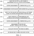
- FIG. 3 is a description of an example of a process for measuring water cut in a liquid hydrocarbon sample.
- dry xylene was injected into a 10 ml measurement cell with dry nitrogen.
- the temperature of the measurement cell was controlled at 40 °C.
- water content in dry solvent was measured. The water content was found to be 50 parts per million by volume (ppmv).
- ppmv parts per million by volume
- the water cut measurement system described here can be calibrated. To do so, two samples can be drawn, either simultaneously or at different time instants. The samples can be diluted differently. For example, the first sample can be diluted at a 1:10 ratio, and the second sample can be diluted at a 1:20 ratio with a dilusion fluid, for example, the low-dielectric solvent.
- the water cut measurement can be implemented for both samples are described earlier. If the system operates as intended, then the water cut of the first sample will be twice that of the second sample. When similar calibration is implemented for multiple samples with a linear range of dilution ratios, the water cut profile for the samples will also be linear.
- processing two water samples of the same concentration (1:10 ratio or 1:20 ratio) in parallel allows solving a system of two equations with two unknowns (the original water contents in the hydrocarbons and the solvent), enabling measurement of the water content of the mixture components.
- the techniques described in this disclosure allow measuring the water content of water-saturated petroleum fluids that contain dispersed droplets.
- Implementing the techniques enables the water present in the form of droplets in the crude oil to be dissolved in a dry solvent, and hence to be easily measured as part of a homogeneous mixture.
- By varying the volume ratio of solvent and petroleum fluid it is possible to cover a very wide range (for example, from 0% to 100%) of water concentrations in a petroleum fluid.
Landscapes
- Chemical & Material Sciences (AREA)
- Life Sciences & Earth Sciences (AREA)
- Health & Medical Sciences (AREA)
- Analytical Chemistry (AREA)
- Biochemistry (AREA)
- Pathology (AREA)
- Immunology (AREA)
- General Physics & Mathematics (AREA)
- General Health & Medical Sciences (AREA)
- Physics & Mathematics (AREA)
- Engineering & Computer Science (AREA)
- Medicinal Chemistry (AREA)
- Oil, Petroleum & Natural Gas (AREA)
- Food Science & Technology (AREA)
- Chemical Kinetics & Catalysis (AREA)
- General Chemical & Material Sciences (AREA)
- Hydrology & Water Resources (AREA)
- Sampling And Sample Adjustment (AREA)
- Investigating Or Analyzing Non-Biological Materials By The Use Of Chemical Means (AREA)
- Colloid Chemistry (AREA)
- Production Of Liquid Hydrocarbon Mixture For Refining Petroleum (AREA)
Claims (13)
- Verfahren, umfassend:Aufnehmen (202) einer flüssigen Kohlenwasserstoffprobe aus einer Flowline (102), die den flüssigen Kohlenwasserstoff führt, wobei die flüssige Kohlenwasserstoffprobe flüssigen Kohlenwasserstoff und flüssiges Wasser in einer Konzentration, die über einem Wassersättigungsniveau liegt, umfasst;Mischen (204) der flüssigen Kohlenwasserstoffprobe mit einem Lösungsmittel, das einen Wassergehalt unterhalb eines Schwellenwerts für den Wassergehalt aufweist, wobei die Konzentration von flüssigem Wasser in einem Gemisch aus dem Lösungsmittel und der flüssigen Kohlenwasserstoffprobe unterhalb des Wassersättigungsniveaus liegt; undnach dem Mischen der flüssigen Kohlenwasserstoffprobe mit dem Lösungsmittel Messen eines Wasseranteils des Gemischs aus der flüssigen Kohlenwasserstoffprobe und dem Lösungsmittel und Bestimmen (206) eines Wassergehalts in der flüssigen Kohlenwasserstoffprobe.
- Verfahren nach Anspruch 1, wobei das Aufnehmen der flüssigen Kohlenwasserstoffprobe das Fließenlassen der flüssigen Kohlenwasserstoffprobe in eine Messzelle (106) umfasst.
- Verfahren nach Anspruch 2, ferner umfassend das Kontrollieren einer Temperatur der Messzelle (106), um im Wesentlichen bei einer Temperatur zu bleiben, vor dem Mischen der flüssigen Kohlenwasserstoffprobe mit dem Lösungsmittel und während des Bestimmens des Wassergehalts des flüssigen Wassers in der flüssigen Kohlenwasserstoffprobe.
- Verfahren nach Anspruch 3, wobei die Temperatur 40 °C beträgt.
- Verfahren nach Anspruch 2, wobei das Mischen der flüssigen Kohlenwasserstoffprobe mit einem Lösungsmittel das Fließenlassen des Lösungsmittels in die Messzelle umfasst.
- Verfahren nach Anspruch 5, das vor dem Mischen der flüssige Kohlenwasserstoffprobe mit dem Lösungsmittel ferner Folgendes umfasst:Bestimmen, dass ein Wassergehalt des Lösungsmittels über einem Schwellenwert für den Wassergehalt liegt; undals Reaktion auf das Bestimmen, dass der Wassergehalt des Lösungsmittels über dem Schwellenwert für den Wassergehalt liegt, Übertragen eines Alarmsignals, um das Mischen der flüssigen Kohlenwasserstoffprobe mit dem Lösungsmittel zu beenden.
- Verfahren nach Anspruch 1, ferner umfassend:Übertragen des Wassergehalts an ein Computersystem; undAnzeigen des Wassergehalts auf einer Anzeigevorrichtung, die mit dem Computersystem verbunden ist.
- Verfahren nach Anspruch 1, ferner umfassend das Fließenlassen des Gemischs des Lösungsmittels und der flüssigen Kohlenwasserstoffprobe zu der Flowline.
- Verfahren nach Anspruch 1, wobei die flüssige Kohlenwasserstoffprobe eine erste flüssige Kohlenwasserstoffprobe ist, wobei das Lösungsmittel ein erstes Lösungsmittel ist, der Wassergehalt ein erster Wassergehalt ist, wobei der erste Wassergehalt zu einem ersten Zeitpunkt bestimmt wird, wobei das Verfahren zu einer jeweiligen Mehrzahl von Zeitpunkten im Anschluss an den ersten Zeitpunkt ferner Folgendes umfasst:Aufnehmen einer jeweiligen Mehrzahl von flüssigen Kohlenwasserstoffproben aus der Flowline, wobei jede der flüssigen Kohlenwasserstoffproben flüssigen Kohlenwasserstoff und flüssiges Wasser in einer jeweiligen Konzentration umfasst, die über einem Wassersättigungsniveau liegt;Mischen jeder der flüssigen Kohlenwasserstoffproben mit dem Lösungsmittel;nach dem Mischen von jeder der flüssigen Kohlenwasserstoffproben mit dem Lösungsmittel Bestimmen eines Wassergehalts von flüssigem Wasser in jeder der flüssigen Kohlenwasserstoffproben; undEntwickeln eines Wasseranteilprofils für die erste flüssige Kohlenwasserstoffprobe und die Mehrzahl von flüssigen Kohlenwasserstoffproben über eine Dauer, die den ersten Zeitpunkt und die Mehrzahl von Zeitpunkten umfasst.
- Verfahren nach Anspruch 1, wobei das Lösungsmittel trockenes Xylol umfasst.
- Verfahren nach einem der vorstehenden Ansprüche, wobei die Flowline (102) von einem Bohrlochkopf zu einer anderen Position verläuft, zum Beispiel zu einer Gas-Öl-Trennanlage, d. h. "GOSP" - "Gas Oil Separation Plant".
- Verfahren nach einem der vorstehenden Ansprüche 1 bis 10, wobei die Flowline (102) von einer GOSP zu einer Rohölexportterminal- oder - stabilisierungsanlage verläuft.
- Verfahren nach einem der vorstehenden Ansprüche, wobei der flüssige Kohlenwasserstoff flüssiges Rohöl ist.
Applications Claiming Priority (2)
| Application Number | Priority Date | Filing Date | Title |
|---|---|---|---|
| US16/575,082 US11131660B2 (en) | 2019-09-18 | 2019-09-18 | Method and apparatus to measure water content of petroleum fluids |
| PCT/US2020/051227 WO2021055571A1 (en) | 2019-09-18 | 2020-09-17 | Method and apparatus to measure water content of petroleum fluids |
Publications (2)
| Publication Number | Publication Date |
|---|---|
| EP4031862A1 EP4031862A1 (de) | 2022-07-27 |
| EP4031862B1 true EP4031862B1 (de) | 2024-11-13 |
Family
ID=72709870
Family Applications (1)
| Application Number | Title | Priority Date | Filing Date |
|---|---|---|---|
| EP20785649.3A Active EP4031862B1 (de) | 2019-09-18 | 2020-09-17 | Verfahren und vorrichtung zur messung des wassergehalts von erdölflüssigkeiten |
Country Status (7)
| Country | Link |
|---|---|
| US (1) | US11131660B2 (de) |
| EP (1) | EP4031862B1 (de) |
| JP (1) | JP7607645B2 (de) |
| KR (1) | KR20220065011A (de) |
| CN (1) | CN114402199A (de) |
| SA (1) | SA522431991B1 (de) |
| WO (1) | WO2021055571A1 (de) |
Families Citing this family (9)
| Publication number | Priority date | Publication date | Assignee | Title |
|---|---|---|---|---|
| US11422122B2 (en) * | 2020-06-22 | 2022-08-23 | Saudi Arabian Oil Company | Measuring water content of petroleum fluids using dried petroleum fluid solvent |
| DE102021107684A1 (de) | 2021-03-26 | 2022-09-29 | Truedyne Sensors AG | Verfahren und Vorrichtung zum Bestimmen eines Probenstromkonzentrationswerts eines Analyten in einem Probenstrom |
| CN113341065B (zh) * | 2021-04-26 | 2023-11-28 | 中国石油天然气集团有限公司 | 预脱水剂技术评价方法 |
| US11548784B1 (en) | 2021-10-26 | 2023-01-10 | Saudi Arabian Oil Company | Treating sulfur dioxide containing stream by acid aqueous absorption |
| US12116326B2 (en) | 2021-11-22 | 2024-10-15 | Saudi Arabian Oil Company | Conversion of hydrogen sulfide and carbon dioxide into hydrocarbons using non-thermal plasma and a catalyst |
| US12179129B2 (en) | 2021-12-14 | 2024-12-31 | Saudi Arabian Oil Company | Synergetic solvent for crude oil emulsion breakers |
| US11926799B2 (en) | 2021-12-14 | 2024-03-12 | Saudi Arabian Oil Company | 2-iso-alkyl-2-(4-hydroxyphenyl)propane derivatives used as emulsion breakers for crude oil |
| KR102819827B1 (ko) * | 2022-12-23 | 2025-06-16 | 앤츠이엔씨 주식회사 | 염제거 장치 효율을 높이기 위한 워터컷 미터 측정 시스템 및 방법 |
| US12515950B2 (en) | 2024-01-02 | 2026-01-06 | Saudi Arabian Oil Company | H2 recovery and CO2 separation using membrane |
Family Cites Families (31)
| Publication number | Priority date | Publication date | Assignee | Title |
|---|---|---|---|---|
| US2758477A (en) * | 1955-04-07 | 1956-08-14 | Shell Dev | Water cut apparatus |
| US3133437A (en) * | 1961-05-22 | 1964-05-19 | Phillips Petroleum Co | Measuring the water content in oil and water mixtures |
| US3222918A (en) * | 1962-07-05 | 1965-12-14 | Phillips Petroleum Co | Measurement of specific gravity and basic sediment and water content of oil |
| FR1504908A (fr) * | 1966-12-06 | 1967-12-08 | Solvay | Appareil perfectionné pour la détection continue de l'eau dans les liquides organiques |
| US3528775A (en) * | 1967-01-25 | 1970-09-15 | Mobil Oil Corp | Method and apparatus for testing petroleum products for water content |
| US3727049A (en) | 1967-05-01 | 1973-04-10 | Us Navy | Method for determining immiscible water content of fluids by spectrophotometer |
| US3462596A (en) * | 1967-12-01 | 1969-08-19 | Raymond A Saunders | Measuring water content of heavy petroleum fuel oils by infrared analysis |
| US3539917A (en) * | 1968-04-24 | 1970-11-10 | Panametrics | Method of measuring the water content of liquid hydrocarbons |
| US3546926A (en) * | 1969-04-29 | 1970-12-15 | Shell Oil Co | Bottom sediment and water monitor |
| US4301400A (en) * | 1979-12-26 | 1981-11-17 | Texaco Inc. | Microwave water in crude monitor |
| SU1183890A1 (ru) * | 1983-06-20 | 1985-10-07 | Институт Теоретических Проблем Химической Технологии Ан Азсср | Способ спектрофотометрического определени воды в органических растворител х |
| JPS6140555A (ja) | 1985-04-26 | 1986-02-26 | Hiranuma Sangyo Kk | 潤滑油等の含有水分測定方法とその装置 |
| US5067345A (en) | 1988-07-05 | 1991-11-26 | Mougne Marcel L | Method and apparatus for measuring and calculating bulk water in crude oil or bulk water in steam |
| US5187101A (en) * | 1990-11-06 | 1993-02-16 | Mitsubishi Kasei Corporation | Electrolytic solution for karl fischer's coulometric titration and method for measuring water content using same |
| US5259239A (en) | 1992-04-10 | 1993-11-09 | Scott Gaisford | Hydrocarbon mass flow meter |
| CA2432403A1 (en) * | 2003-06-13 | 2004-12-13 | Kiran Vadgama | Method for testing liquid hydrocarbons using refractive index |
| NO323247B1 (no) | 2003-12-09 | 2007-02-12 | Multi Phase Meters As | Fremgangsmåte og strømningsmåler for å bestemme strømningsratene til en flerfaseblanding |
| DE102004010650B4 (de) * | 2004-02-28 | 2006-04-20 | Martechnic Gmbh | Reagenz und Verfahren zur Wassergehaltsbestimmung in Ölen |
| US7233001B2 (en) * | 2005-02-24 | 2007-06-19 | Weatherford/Lamb, Inc. | Multi-channel infrared optical phase fraction meter |
| US8268629B2 (en) * | 2005-06-21 | 2012-09-18 | dTEC Systems L.L.C. | Method for the measurement of water and water-soluble components in non-aqueous liquids |
| US8323392B2 (en) | 2006-02-13 | 2012-12-04 | Eastman Kodak Company | Oil-in-oil dispersions stabilized by solid particles and methods of making the same |
| US8068218B2 (en) * | 2008-04-13 | 2011-11-29 | Agilent Technologies, Inc. | Water in oil measurement using stabilizer |
| US8570497B2 (en) | 2010-02-08 | 2013-10-29 | Phillips 66 Company | Oil in water analyzer |
| FR2970082B1 (fr) | 2011-01-05 | 2013-01-11 | Total Sa | Methode de dosage des huiles lourdes |
| US9448221B2 (en) | 2011-05-18 | 2016-09-20 | Saudi Arabian Oil Company | Method, solvent formulation and apparatus for the measurement of the salt content in petroleum fluids |
| US10088442B2 (en) | 2011-10-28 | 2018-10-02 | Saudi Arabian Oil Company | Combined water cut and salinity meter |
| CN105974098B (zh) | 2016-07-15 | 2018-04-06 | 西安石油大学 | 一种高含水油井井口含水率在线检测装置 |
| US10067091B2 (en) * | 2016-07-29 | 2018-09-04 | Saudi Arabian Oil Company | Integrated sediment and water analysis device and method |
| CN107655922B (zh) * | 2017-09-05 | 2019-06-11 | 中国石油天然气股份有限公司 | 一种基于核磁共振的烃源岩含水量无损检测的方法 |
| US11422122B2 (en) * | 2020-06-22 | 2022-08-23 | Saudi Arabian Oil Company | Measuring water content of petroleum fluids using dried petroleum fluid solvent |
| CN116265943A (zh) * | 2021-12-18 | 2023-06-20 | 大庆油田有限责任公司 | 一种页岩油田油井采出液含水率测试方法 |
-
2019
- 2019-09-18 US US16/575,082 patent/US11131660B2/en active Active
-
2020
- 2020-09-17 WO PCT/US2020/051227 patent/WO2021055571A1/en not_active Ceased
- 2020-09-17 KR KR1020227012784A patent/KR20220065011A/ko not_active Ceased
- 2020-09-17 JP JP2022518010A patent/JP7607645B2/ja active Active
- 2020-09-17 EP EP20785649.3A patent/EP4031862B1/de active Active
- 2020-09-17 CN CN202080064984.3A patent/CN114402199A/zh active Pending
-
2022
- 2022-03-17 SA SA522431991A patent/SA522431991B1/ar unknown
Also Published As
| Publication number | Publication date |
|---|---|
| US11131660B2 (en) | 2021-09-28 |
| WO2021055571A1 (en) | 2021-03-25 |
| KR20220065011A (ko) | 2022-05-19 |
| CN114402199A (zh) | 2022-04-26 |
| EP4031862A1 (de) | 2022-07-27 |
| JP2022548767A (ja) | 2022-11-21 |
| US20210080446A1 (en) | 2021-03-18 |
| SA522431991B1 (ar) | 2023-10-15 |
| JP7607645B2 (ja) | 2024-12-27 |
Similar Documents
| Publication | Publication Date | Title |
|---|---|---|
| US11131660B2 (en) | Method and apparatus to measure water content of petroleum fluids | |
| EP4168797B1 (de) | Messung des wassergehalts von erdölflüssigkeiten unter verwendung von getrocknetem erdöllösungsmittel | |
| US8606531B2 (en) | System and method for spot check analysis or spot sampling of a multiphase mixture flowing in a pipeline | |
| US9696193B2 (en) | Real-time measurement of reservoir fluid properties | |
| US9116104B2 (en) | Method and apparatus for detecting water in a fluid media | |
| CA2386468C (en) | Foam monitoring and control system | |
| US5612490A (en) | Method and apparatus for measuring phases in emulsions | |
| US7599803B2 (en) | Hydrocarbon well test method and system | |
| US11833445B2 (en) | Method and device for separating and measuring multiphase immiscible fluid mixtures using an improved analytical cell | |
| US12146779B2 (en) | Method and system for separating and analyzing multiphase immiscible fluid mixtures | |
| GB2225863A (en) | Flow measuring system for a gas/water/oil mixture | |
| US4045671A (en) | Method and apparatus for continuously monitoring the presence of oil in water | |
| US5191786A (en) | Method for detecting the presence and concentration of relatively low molecular weight components in a liquid | |
| US20200094201A1 (en) | Equilibrator for Rapid and Continuous Detection of a Gas in a Liquid | |
| US11833449B2 (en) | Method and device for separating and measuring multiphase immiscible fluid mixtures | |
| RU2749256C1 (ru) | Мобильный эталон 2-го разряда для поверки установок измерения скважинной продукции | |
| CA2551176C (en) | Autocalibrated multiphase fluid characterization using extrema of time series | |
| JP2023536484A (ja) | 随伴水中の分散油相のオンライン測定 | |
| US11761945B2 (en) | Water analysis unit of a system for separating and analyzing a multiphase immiscible fluid mixture and corresponding method | |
| Clarke | Sampling for on-line analysis | |
| Millington | The Performance of The Fluenta MPFM 900 Phase Fraction Meter | |
| JPH0679011B2 (ja) | 非水性試料のphを連続的に測定する方法及び装置 | |
| Fransen | Automatic well testing using a two-phase separator | |
| JPH0150444B2 (de) | ||
| Walsh et al. | New Techniques in the Gathering, Measurement, and Sampling of Crude Oil |
Legal Events
| Date | Code | Title | Description |
|---|---|---|---|
| STAA | Information on the status of an ep patent application or granted ep patent |
Free format text: STATUS: UNKNOWN |
|
| STAA | Information on the status of an ep patent application or granted ep patent |
Free format text: STATUS: THE INTERNATIONAL PUBLICATION HAS BEEN MADE |
|
| PUAI | Public reference made under article 153(3) epc to a published international application that has entered the european phase |
Free format text: ORIGINAL CODE: 0009012 |
|
| STAA | Information on the status of an ep patent application or granted ep patent |
Free format text: STATUS: REQUEST FOR EXAMINATION WAS MADE |
|
| 17P | Request for examination filed |
Effective date: 20220323 |
|
| AK | Designated contracting states |
Kind code of ref document: A1 Designated state(s): AL AT BE BG CH CY CZ DE DK EE ES FI FR GB GR HR HU IE IS IT LI LT LU LV MC MK MT NL NO PL PT RO RS SE SI SK SM TR |
|
| DAV | Request for validation of the european patent (deleted) | ||
| DAX | Request for extension of the european patent (deleted) | ||
| P01 | Opt-out of the competence of the unified patent court (upc) registered |
Effective date: 20230528 |
|
| GRAP | Despatch of communication of intention to grant a patent |
Free format text: ORIGINAL CODE: EPIDOSNIGR1 |
|
| STAA | Information on the status of an ep patent application or granted ep patent |
Free format text: STATUS: GRANT OF PATENT IS INTENDED |
|
| GRAJ | Information related to disapproval of communication of intention to grant by the applicant or resumption of examination proceedings by the epo deleted |
Free format text: ORIGINAL CODE: EPIDOSDIGR1 |
|
| INTG | Intention to grant announced |
Effective date: 20240425 |
|
| RIN1 | Information on inventor provided before grant (corrected) |
Inventor name: LESS, SIMONE Inventor name: DUVAL, SEBASTIEN A. Inventor name: AHMED, ELAF A. |
|
| STAA | Information on the status of an ep patent application or granted ep patent |
Free format text: STATUS: REQUEST FOR EXAMINATION WAS MADE |
|
| GRAP | Despatch of communication of intention to grant a patent |
Free format text: ORIGINAL CODE: EPIDOSNIGR1 |
|
| STAA | Information on the status of an ep patent application or granted ep patent |
Free format text: STATUS: GRANT OF PATENT IS INTENDED |
|
| INTC | Intention to grant announced (deleted) | ||
| INTG | Intention to grant announced |
Effective date: 20240612 |
|
| GRAS | Grant fee paid |
Free format text: ORIGINAL CODE: EPIDOSNIGR3 |
|
| GRAA | (expected) grant |
Free format text: ORIGINAL CODE: 0009210 |
|
| STAA | Information on the status of an ep patent application or granted ep patent |
Free format text: STATUS: THE PATENT HAS BEEN GRANTED |
|
| AK | Designated contracting states |
Kind code of ref document: B1 Designated state(s): AL AT BE BG CH CY CZ DE DK EE ES FI FR GB GR HR HU IE IS IT LI LT LU LV MC MK MT NL NO PL PT RO RS SE SI SK SM TR |
|
| REG | Reference to a national code |
Ref country code: GB Ref legal event code: FG4D |
|
| REG | Reference to a national code |
Ref country code: CH Ref legal event code: EP |
|
| REG | Reference to a national code |
Ref country code: DE Ref legal event code: R096 Ref document number: 602020041373 Country of ref document: DE |
|
| REG | Reference to a national code |
Ref country code: IE Ref legal event code: FG4D |
|
| REG | Reference to a national code |
Ref country code: NL Ref legal event code: FP |
|
| REG | Reference to a national code |
Ref country code: LT Ref legal event code: MG9D |
|
| PG25 | Lapsed in a contracting state [announced via postgrant information from national office to epo] |
Ref country code: IS Free format text: LAPSE BECAUSE OF FAILURE TO SUBMIT A TRANSLATION OF THE DESCRIPTION OR TO PAY THE FEE WITHIN THE PRESCRIBED TIME-LIMIT Effective date: 20250313 Ref country code: PT Free format text: LAPSE BECAUSE OF FAILURE TO SUBMIT A TRANSLATION OF THE DESCRIPTION OR TO PAY THE FEE WITHIN THE PRESCRIBED TIME-LIMIT Effective date: 20250313 Ref country code: HR Free format text: LAPSE BECAUSE OF FAILURE TO SUBMIT A TRANSLATION OF THE DESCRIPTION OR TO PAY THE FEE WITHIN THE PRESCRIBED TIME-LIMIT Effective date: 20241113 |
|
| PG25 | Lapsed in a contracting state [announced via postgrant information from national office to epo] |
Ref country code: FI Free format text: LAPSE BECAUSE OF FAILURE TO SUBMIT A TRANSLATION OF THE DESCRIPTION OR TO PAY THE FEE WITHIN THE PRESCRIBED TIME-LIMIT Effective date: 20241113 |
|
| REG | Reference to a national code |
Ref country code: AT Ref legal event code: MK05 Ref document number: 1742049 Country of ref document: AT Kind code of ref document: T Effective date: 20241113 |
|
| PG25 | Lapsed in a contracting state [announced via postgrant information from national office to epo] |
Ref country code: BG Free format text: LAPSE BECAUSE OF FAILURE TO SUBMIT A TRANSLATION OF THE DESCRIPTION OR TO PAY THE FEE WITHIN THE PRESCRIBED TIME-LIMIT Effective date: 20241113 |
|
| PG25 | Lapsed in a contracting state [announced via postgrant information from national office to epo] |
Ref country code: ES Free format text: LAPSE BECAUSE OF FAILURE TO SUBMIT A TRANSLATION OF THE DESCRIPTION OR TO PAY THE FEE WITHIN THE PRESCRIBED TIME-LIMIT Effective date: 20241113 |
|
| PG25 | Lapsed in a contracting state [announced via postgrant information from national office to epo] |
Ref country code: NO Free format text: LAPSE BECAUSE OF FAILURE TO SUBMIT A TRANSLATION OF THE DESCRIPTION OR TO PAY THE FEE WITHIN THE PRESCRIBED TIME-LIMIT Effective date: 20250213 |
|
| PG25 | Lapsed in a contracting state [announced via postgrant information from national office to epo] |
Ref country code: LV Free format text: LAPSE BECAUSE OF FAILURE TO SUBMIT A TRANSLATION OF THE DESCRIPTION OR TO PAY THE FEE WITHIN THE PRESCRIBED TIME-LIMIT Effective date: 20241113 Ref country code: AT Free format text: LAPSE BECAUSE OF FAILURE TO SUBMIT A TRANSLATION OF THE DESCRIPTION OR TO PAY THE FEE WITHIN THE PRESCRIBED TIME-LIMIT Effective date: 20241113 Ref country code: GR Free format text: LAPSE BECAUSE OF FAILURE TO SUBMIT A TRANSLATION OF THE DESCRIPTION OR TO PAY THE FEE WITHIN THE PRESCRIBED TIME-LIMIT Effective date: 20250214 |
|
| PG25 | Lapsed in a contracting state [announced via postgrant information from national office to epo] |
Ref country code: PL Free format text: LAPSE BECAUSE OF FAILURE TO SUBMIT A TRANSLATION OF THE DESCRIPTION OR TO PAY THE FEE WITHIN THE PRESCRIBED TIME-LIMIT Effective date: 20241113 |
|
| PG25 | Lapsed in a contracting state [announced via postgrant information from national office to epo] |
Ref country code: RS Free format text: LAPSE BECAUSE OF FAILURE TO SUBMIT A TRANSLATION OF THE DESCRIPTION OR TO PAY THE FEE WITHIN THE PRESCRIBED TIME-LIMIT Effective date: 20250213 |
|
| PG25 | Lapsed in a contracting state [announced via postgrant information from national office to epo] |
Ref country code: SM Free format text: LAPSE BECAUSE OF FAILURE TO SUBMIT A TRANSLATION OF THE DESCRIPTION OR TO PAY THE FEE WITHIN THE PRESCRIBED TIME-LIMIT Effective date: 20241113 |
|
| PG25 | Lapsed in a contracting state [announced via postgrant information from national office to epo] |
Ref country code: DK Free format text: LAPSE BECAUSE OF FAILURE TO SUBMIT A TRANSLATION OF THE DESCRIPTION OR TO PAY THE FEE WITHIN THE PRESCRIBED TIME-LIMIT Effective date: 20241113 |
|
| PG25 | Lapsed in a contracting state [announced via postgrant information from national office to epo] |
Ref country code: EE Free format text: LAPSE BECAUSE OF FAILURE TO SUBMIT A TRANSLATION OF THE DESCRIPTION OR TO PAY THE FEE WITHIN THE PRESCRIBED TIME-LIMIT Effective date: 20241113 |
|
| PG25 | Lapsed in a contracting state [announced via postgrant information from national office to epo] |
Ref country code: RO Free format text: LAPSE BECAUSE OF FAILURE TO SUBMIT A TRANSLATION OF THE DESCRIPTION OR TO PAY THE FEE WITHIN THE PRESCRIBED TIME-LIMIT Effective date: 20241113 |
|
| PG25 | Lapsed in a contracting state [announced via postgrant information from national office to epo] |
Ref country code: SK Free format text: LAPSE BECAUSE OF FAILURE TO SUBMIT A TRANSLATION OF THE DESCRIPTION OR TO PAY THE FEE WITHIN THE PRESCRIBED TIME-LIMIT Effective date: 20241113 |
|
| PG25 | Lapsed in a contracting state [announced via postgrant information from national office to epo] |
Ref country code: CZ Free format text: LAPSE BECAUSE OF FAILURE TO SUBMIT A TRANSLATION OF THE DESCRIPTION OR TO PAY THE FEE WITHIN THE PRESCRIBED TIME-LIMIT Effective date: 20241113 |
|
| PG25 | Lapsed in a contracting state [announced via postgrant information from national office to epo] |
Ref country code: IT Free format text: LAPSE BECAUSE OF FAILURE TO SUBMIT A TRANSLATION OF THE DESCRIPTION OR TO PAY THE FEE WITHIN THE PRESCRIBED TIME-LIMIT Effective date: 20241113 |
|
| REG | Reference to a national code |
Ref country code: DE Ref legal event code: R097 Ref document number: 602020041373 Country of ref document: DE |
|
| PG25 | Lapsed in a contracting state [announced via postgrant information from national office to epo] |
Ref country code: SE Free format text: LAPSE BECAUSE OF FAILURE TO SUBMIT A TRANSLATION OF THE DESCRIPTION OR TO PAY THE FEE WITHIN THE PRESCRIBED TIME-LIMIT Effective date: 20241113 |
|
| PLBE | No opposition filed within time limit |
Free format text: ORIGINAL CODE: 0009261 |
|
| STAA | Information on the status of an ep patent application or granted ep patent |
Free format text: STATUS: NO OPPOSITION FILED WITHIN TIME LIMIT |
|
| PGFP | Annual fee paid to national office [announced via postgrant information from national office to epo] |
Ref country code: DE Payment date: 20250902 Year of fee payment: 6 |
|
| PGFP | Annual fee paid to national office [announced via postgrant information from national office to epo] |
Ref country code: NL Payment date: 20250912 Year of fee payment: 6 |
|
| PGFP | Annual fee paid to national office [announced via postgrant information from national office to epo] |
Ref country code: FR Payment date: 20250908 Year of fee payment: 6 |
|
| 26N | No opposition filed |
Effective date: 20250814 |
|
| REG | Reference to a national code |
Ref country code: CH Ref legal event code: H13 Free format text: ST27 STATUS EVENT CODE: U-0-0-H10-H13 (AS PROVIDED BY THE NATIONAL OFFICE) Effective date: 20260504 |