EP4031813B1 - System zur wärmerückgewinnung aus duschabflusswasser und teilesatz für ein solches system - Google Patents
System zur wärmerückgewinnung aus duschabflusswasser und teilesatz für ein solches system Download PDFInfo
- Publication number
- EP4031813B1 EP4031813B1 EP20767886.3A EP20767886A EP4031813B1 EP 4031813 B1 EP4031813 B1 EP 4031813B1 EP 20767886 A EP20767886 A EP 20767886A EP 4031813 B1 EP4031813 B1 EP 4031813B1
- Authority
- EP
- European Patent Office
- Prior art keywords
- heat exchanger
- tray
- inlet
- outlet
- fluid flow
- Prior art date
- Legal status (The legal status is an assumption and is not a legal conclusion. Google has not performed a legal analysis and makes no representation as to the accuracy of the status listed.)
- Active
Links
Images


Classifications
-
- F—MECHANICAL ENGINEERING; LIGHTING; HEATING; WEAPONS; BLASTING
- F24—HEATING; RANGES; VENTILATING
- F24D—DOMESTIC- OR SPACE-HEATING SYSTEMS, e.g. CENTRAL HEATING SYSTEMS; DOMESTIC HOT-WATER SUPPLY SYSTEMS; ELEMENTS OR COMPONENTS THEREFOR
- F24D17/00—Domestic hot-water supply systems
- F24D17/0005—Domestic hot-water supply systems using recuperation of waste heat
-
- E—FIXED CONSTRUCTIONS
- E03—WATER SUPPLY; SEWERAGE
- E03C—DOMESTIC PLUMBING INSTALLATIONS FOR FRESH WATER OR WASTE WATER; SINKS
- E03C1/00—Domestic plumbing installations for fresh water or waste water; Sinks
- E03C1/02—Plumbing installations for fresh water
- E03C1/04—Water-basin installations specially adapted to wash-basins or baths
- E03C1/0408—Water installations especially for showers
-
- F—MECHANICAL ENGINEERING; LIGHTING; HEATING; WEAPONS; BLASTING
- F28—HEAT EXCHANGE IN GENERAL
- F28D—HEAT-EXCHANGE APPARATUS, NOT PROVIDED FOR IN ANOTHER SUBCLASS, IN WHICH THE HEAT-EXCHANGE MEDIA DO NOT COME INTO DIRECT CONTACT
- F28D1/00—Heat-exchange apparatus having stationary conduit assemblies for one heat-exchange medium only, the media being in contact with different sides of the conduit wall, in which the other heat-exchange medium is a large body of fluid, e.g. domestic or motor car radiators
- F28D1/02—Heat-exchange apparatus having stationary conduit assemblies for one heat-exchange medium only, the media being in contact with different sides of the conduit wall, in which the other heat-exchange medium is a large body of fluid, e.g. domestic or motor car radiators with heat-exchange conduits immersed in the body of fluid
- F28D1/04—Heat-exchange apparatus having stationary conduit assemblies for one heat-exchange medium only, the media being in contact with different sides of the conduit wall, in which the other heat-exchange medium is a large body of fluid, e.g. domestic or motor car radiators with heat-exchange conduits immersed in the body of fluid with tubular conduits
- F28D1/047—Heat-exchange apparatus having stationary conduit assemblies for one heat-exchange medium only, the media being in contact with different sides of the conduit wall, in which the other heat-exchange medium is a large body of fluid, e.g. domestic or motor car radiators with heat-exchange conduits immersed in the body of fluid with tubular conduits the conduits being bent, e.g. in a serpentine or zig-zag
- F28D1/0477—Heat-exchange apparatus having stationary conduit assemblies for one heat-exchange medium only, the media being in contact with different sides of the conduit wall, in which the other heat-exchange medium is a large body of fluid, e.g. domestic or motor car radiators with heat-exchange conduits immersed in the body of fluid with tubular conduits the conduits being bent, e.g. in a serpentine or zig-zag the conduits being bent in a serpentine or zig-zag
-
- F—MECHANICAL ENGINEERING; LIGHTING; HEATING; WEAPONS; BLASTING
- F28—HEAT EXCHANGE IN GENERAL
- F28D—HEAT-EXCHANGE APPARATUS, NOT PROVIDED FOR IN ANOTHER SUBCLASS, IN WHICH THE HEAT-EXCHANGE MEDIA DO NOT COME INTO DIRECT CONTACT
- F28D21/00—Heat-exchange apparatus not covered by any of the groups F28D1/00 - F28D20/00
- F28D21/0001—Recuperative heat exchangers
- F28D21/0012—Recuperative heat exchangers the heat being recuperated from waste water or from condensates
-
- E—FIXED CONSTRUCTIONS
- E03—WATER SUPPLY; SEWERAGE
- E03C—DOMESTIC PLUMBING INSTALLATIONS FOR FRESH WATER OR WASTE WATER; SINKS
- E03C1/00—Domestic plumbing installations for fresh water or waste water; Sinks
- E03C2001/005—Installations allowing recovery of heat from waste water for warming up fresh water
-
- F—MECHANICAL ENGINEERING; LIGHTING; HEATING; WEAPONS; BLASTING
- F24—HEATING; RANGES; VENTILATING
- F24D—DOMESTIC- OR SPACE-HEATING SYSTEMS, e.g. CENTRAL HEATING SYSTEMS; DOMESTIC HOT-WATER SUPPLY SYSTEMS; ELEMENTS OR COMPONENTS THEREFOR
- F24D2200/00—Heat sources or energy sources
- F24D2200/16—Waste heat
- F24D2200/20—Sewage water
-
- Y—GENERAL TAGGING OF NEW TECHNOLOGICAL DEVELOPMENTS; GENERAL TAGGING OF CROSS-SECTIONAL TECHNOLOGIES SPANNING OVER SEVERAL SECTIONS OF THE IPC; TECHNICAL SUBJECTS COVERED BY FORMER USPC CROSS-REFERENCE ART COLLECTIONS [XRACs] AND DIGESTS
- Y02—TECHNOLOGIES OR APPLICATIONS FOR MITIGATION OR ADAPTATION AGAINST CLIMATE CHANGE
- Y02B—CLIMATE CHANGE MITIGATION TECHNOLOGIES RELATED TO BUILDINGS, e.g. HOUSING, HOUSE APPLIANCES OR RELATED END-USER APPLICATIONS
- Y02B30/00—Energy efficient heating, ventilation or air conditioning [HVAC]
- Y02B30/18—Domestic hot-water supply systems using recuperated or waste heat
-
- Y—GENERAL TAGGING OF NEW TECHNOLOGICAL DEVELOPMENTS; GENERAL TAGGING OF CROSS-SECTIONAL TECHNOLOGIES SPANNING OVER SEVERAL SECTIONS OF THE IPC; TECHNICAL SUBJECTS COVERED BY FORMER USPC CROSS-REFERENCE ART COLLECTIONS [XRACs] AND DIGESTS
- Y02—TECHNOLOGIES OR APPLICATIONS FOR MITIGATION OR ADAPTATION AGAINST CLIMATE CHANGE
- Y02B—CLIMATE CHANGE MITIGATION TECHNOLOGIES RELATED TO BUILDINGS, e.g. HOUSING, HOUSE APPLIANCES OR RELATED END-USER APPLICATIONS
- Y02B30/00—Energy efficient heating, ventilation or air conditioning [HVAC]
- Y02B30/56—Heat recovery units
Definitions
- the present invention is in the field of a heat exchange system for recovery of heat from shower drain water, and its use, for part of the energy spent in the preparation of hot water, which energy is normally lost when the water is drained into the sewage.
- This heat recovery device may be applied to the recovery of energy from hot sanitary water, such as the bath water or kitchen water, either from domestic or industrial use.
- EP3372939 A2 recites a heat exchanger for heating fresh water using heat from wastewater in a shower or bathtub.
- the heat exchanger has a drain pan, a heat exchanger unit which is arranged in the drain pan, and a distributing element for distributing draining wastewater over the heat exchanger unit.
- the heat exchanger unit has multiple tube portions which follow one another sequentially and are connected to one another by diverting portions. Each two horizontally running tube portions which follow one another and which are thus connected by a deflecting portion are arranged one over the other, and wastewater which is dripping or flowing down is sprinkled on or flows over the tube portions one after the other.
- CN102996958 B recites an in-series device for a diversion pipeline.
- the in-series device comprises a body and transition joints, wherein a main liquid inlet, a main liquid outlet, a diversion liquid inlet and a diversion liquid outlet are arranged on the body, the main liquid inlet and the main liquid outlet are not communicated with each other, the main liquid inlet or the main liquid outlet is respectively communicated with the diversion liquid outlet or the diversion liquid inlet, and any one ends of the main liquid inlet and the main liquid outlet are respectively provided with an eccentric transition joint.
- a main liquid inlet channel enters into a branch loop in a diversion way and then returns into a main liquid outlet channel in an in-series way, so that the structure of the diversion pipeline can be optimized.
- the in-series device is particularly suitable for a shower system with a function of recycling waste heat of water after shower, and each eccentric transition joint is adaptive to and compensates the deviation of an outlet of a main pipeline.
- Cold water enters into a heat exchanger in a diversion way and then returns into a shower cold water pipeline to enter into a water collecting pipe after recycling the heat of the water after shower, so that the defect of structural complexity of a diversion pipeline in the prior art can be overcome.
- the in-series device is simple in structure, simple and convenient to install, ordered, attractive in appearance and safe in use.
- US2011289674 A1 recites a heat exchanger for a shower tray can be arranged in the bottom of the shower tray for the heat recovery from wastewater so as to heat fresh water.
- the heat exchanger has a planar cover plate as the drain surface over which the wastewater drains.
- the cover plate forms the bottom of the shower tray, over which a lid that can be removed without the use of tools is arranged as a tread plate.
- the heat exchanger preferably includes a distributor element, which is arranged for distributing the wastewater over the drain surface.
- the distributor element is preferably a retaining element, which retains the wastewater at an upper edge of the drain surface and forms an overflow along the upper edge.
- the CN 102 997 717 B recites a water stop type shower device for effectively recycling heat energy of hot water after shower.
- the water stop type shower device comprises a shower device and a waste heat recycling device, wherein the waste heat recycling device comprises a heat exchange groove and a heat exchange device, the heat exchange device is arranged in the heat exchange groove, the heat exchange device is respectively connected with a heat exchange water outlet pipe and a heat exchange water inlet pipe through a heat exchange pipe collecting base, the heat exchange water outlet pipe and the heat exchange water inlet pipe are respectively communicated with a branch liquid inlet pipe and a branch liquid outlet pipe of a diversion in-series device, and the diversion in-series device is connected with the shower device.
- CN 101 943 278 A recites a valve component which comprises a shell, a valve core arranged in the shell and a handle for controlling the valve core, wherein the valve core comprises a valve core body with a cavity inside and an opening at one end, a bottom cover hermetically buckled at the open end of the valve core body, a fixed piece fixedly arranged on the bottom cover in the cavity inside the valve core body, a sliding piece which can be arranged on the fixed piece in a relatively sliding way and a control rod which is arranged at an end part opposite to the opening of the valve core body on the valve core body and capable of rotating in a pitching way with respect to the valve core body, and a heat energy recovery device comprising the valve component and a heat exchanger.
- the valve core comprises a valve core body with a cavity inside and an opening at one end, a bottom cover hermetically buckled at the open end of the valve core body, a fixed piece fixedly arranged on the bottom cover in the cavity inside the valve core body, a sliding piece which can
- the present invention relates to a heat exchange system for a shower comprising a tray 1 comprising a heat exchanger 18 for exchanging heat from warm shower water to cold inflow water, typically a fluid flow path, such as a meandering fluid flow path, the heat exchanger comprising an inlet 24 and an outlet 25, wherein the heat exchanger is substantially in a direction perpendicular to warm shower water provided through the tray, a double channel 2 for fluid flow, wherein a first channel is adapted to be in fluid connection with a cold water outlet and the heat exchanger inlet 24 and a second channel is adapted to be in fluid connection with the heat exchanger outlet 25 and a shower faucet, and a fluid diverter 3, the diverter comprising a first fluid flow path 6 for receiving cold water from the cold water outlet and transferring cold water to the heat exchanger inlet 24 and a second fluid flow path 7 for receiving warm water from the heat exchanger outlet 25 and transferring said warm water to the shower faucet, and a fixator 10 for fixing to a cold water outlet.
- the present invention provides a solution to one or more of the above-mentioned problems and overcomes drawbacks of the prior art.
- the present heat exchange system may be partly or fully removably attachable, or may be partly or fully integrated, such as in a wall or floor.
- the present system is relatively flat, that is thin.
- a typical height of the tray for instance is less than 10 cm, such as only 4-8 cm.
- the present invention relates to a kit of parts comprising at least one element selected from the present heat exchange system, and a shower faucet, a coupler, a shower wall fitting, a diverter, and a fitting.
- the present heat exchange system may comprise a shower faucet.
- the fluid diverter may be integrated in the shower faucet 13.
- the system is easier to install, consumes less space, and is considered more aesthetic.
- the fluid diverter 3 may comprise a first fluid flow path inlet 8 which is in line with a second fluid flow path outlet 9. Therewith a distance between cold and hot water supply remains substantially equal.
- the first fluid flow path 6 of the fluid diverter may be directed to a first side of the diverter and wherein the second fluid flow path 7 of the diverter may be directed to a second side of the diverter.
- the diverter can be mounted as close as possible to a wall.
- the fixator 10 of the diverter may be a screw-type fitting, and wherein the fixator is rotatable over 360 degrees.
- the present system is therewith easier to install.
- the tray 1 may comprise an inlet 28 for receiving warm shower water, and an outlet 29 for draining shower water.
- the inlet and outlet 24,25 of the heat exchanger 18 may be diagonally placed. Therewith the tray can be installed in various positions (rotated with respect to one and another).
- the tray 1 may comprise a top plate 19, a heat exchanger 18, and a bottom plate 17, preferably a demountable top plate, bottom plate, and heat exchanger. Parts can be replaced easier, the system is easy to clean, and can be produced cheap.
- the heat exchanger 18 preferably may be provided over 5-50% of a surface area of the bottom plate 17. An efficiency is optimal with a minimum of material used.
- the heat exchanger 18 may be substantially in a direction perpendicular to warm shower water provided through the tray 1.
- a good heat transfer efficiency is obtained with low construction costs and a flat construction height.
- a warm water fluid flow path 21 preferably may be provided in a 0.01-4 cm thick horizontal duct, such as a 0.1-1 cm thick horizontal duct, preferably a variable thick horizontal duct. A good efficiency is obtained with a small construction height.
- the tray 1 may comprise a gutter 20 for receiving the double channel 2, where at least one gutter entrance 27 is located in a corner of the tray where no inlet or outlet 24,25 for the heat exchanger is provided.
- the tray can be installed in various positions (rotated with respect to one and another) and is considered more aesthetic.
- the tray 1 comprises supports 31 that provide draining. Therewith a better removal of water, and reduced smell is obtained.
- the tray 1 may comprise fasteners 23 for fixing the heat exchanger 18 to the bottom plate 17, wherein the top plate 19 preferably comprises positioners 33 for forcing the heat exchanger downwards. Therewith improved heat exchange is obtained.
- the bottom plate 17 may comprise bottom plate material 22 in between the heat exchanger 18 over 50-90% of the surface area thereof, wherein a height of said bottom plate material may be variable and is ⁇ 100%, preferably ⁇ 80%, of a height of the heat exchanger adjacent to said heat exchanger or absent where said heat exchanger is provided, preferably isolating bottom plate material. An optimum efficiency is therewith obtained.
- the double channel 2 may be at least partly provided in a casing 36. This is considered more aesthetic.
- the double channel 2 may comprise at least one coupler 37, preferably a coupler with a thread.
- the system is therewith easier to install.
- FIGS A-O show schematically details of the present device.
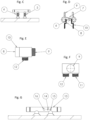
- the invention relates to a system consisting of three interacting parts (see figures A,B) that work together to transfer heat from shower drain water towards the incoming cold water: a tray 1 in which the incoming cold water is preheated by recovering heat from the shower drain water, a double connection tube 2 that transports the incoming cold water from a connection device towards the tray, and the preheated water from the tray back to the connection device, and a connection device 3 that diverts the cold water towards the double connection tube and feeds the preheated water from the double connection tube back into a shower faucet where it is mixed with the incoming hot water.
- a tray 1 in which the incoming cold water is preheated by recovering heat from the shower drain water
- a double connection tube 2 that transports the incoming cold water from a connection device towards the tray, and the preheated water from the tray back to the connection device
- a connection device 3 that diverts the cold water towards the double connection tube and feeds the preheated water from the double connection tube back into a shower faucet where it is
- connection device 3 The objective of the connection device 3 is to connect the double connection tube 2 to the incoming cold water and to the shower faucet without the need of any breaking works (see figure C).
- a common type of shower faucet has a cold water and hot water inlet that are arranged next to each other (often with a heart-to-heart distance of 12 or 15 cm) and that are intended to fit directly onto two fittings in the shower wall with a corresponding heart-to-heart distance.
- the connection device 3 consists of a fluid diverter fitting 4 and an expansion fitting 5. The fluid diverter fitting is placed between the cold water wall fitting and the cold water inlet of the shower faucet (see figures D,E,F).
- a similar diverter fitting is described in patent application CN102996958 B , in which the first fluid flow path inlet and the second fluid flow path outlet of the fitting are eccentric to each other, whereas in the present invention the first fluid flow path inlet 8 and second fluid flow path outlet 9 of the fitting are exactly in line with each other in order to retain the specific heart-to-heart distance.
- the fluid diverter fitting has a 360 degree rotatable threaded coupling 10, to allow the fluid diverter fitting to be always arranged with its first fluid flow path outlet 11 and second fluid flow path inlet 12 faced downward.
- the fluid diverter fitting is constructed in such a way that the installation length is minimized, by diverting the fluid flow paths sideways and downward directly next to the first fluid flow path inlet and the second fluid flow path outlet.
- a simple expansion fitting 5, with the same length as the fluid diverter fitting, is placed on the hot water wall fitting, such that the shower faucet can be mounted directly on the fluid diverter fitting and expansion fitting.
- the double connection tube 2 is connected to the first fluid path outlet and the second fluid flow path inlet of the fluid diverter fitting.
- connection device as a whole can be integrated into an adjusted shower faucet 13, such that the double connection tube 2 can be directly connected to the first fluid flow path outlet 14 and second fluid flow path inlet 15 that are situated on the outside of the casing of the adjusted shower faucet (see figures G,H).
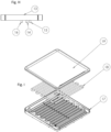
- the purpose of the tray 1 is to transfer heat from the shower drain water to the incoming cold water (see figure I ).
- the tray can either be placed on top of the existing shower tray or shower floor, or can act as a shower tray in itself.
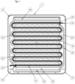
- the basis of the tray 1 is a bottom plate 17 that is constructed in one piece and has two main parts: a warm water fluid flow path 21, through which the shower drain water flows, and a gutter 20 that is surrounding the warm water fluid flow path and is intended to guide and contain the inlet and outlet tubes.
- the shower drain water flows over a meandering heat exchanger tube 18 that is made of heat-conducting material such as copper.
- the flow direction of the shower drain water is perpendicular to the primary direction of the heat exchanger tubes (see figures J,K).
- Such a principle is known from patent application EP3372939 A2 that uses heat exchanger tubes that are situated above each other.
- the heat exchanger tubes are placed in a horizontal arrangement, to be able to increase the number of heat exchanger tubes, and hence the heat transfer efficiency, while reducing the construction height of the tray.
- the straight segments of the meandering heat exchanger tube are situated within the warm water fluid flow path. In the spaces between consecutive straight tube segments, the bottom plate material 22 is elevated up to a height of 100% of the tube diameter, thereby shortening the time to completely submerge the heat exchanger in shower drain water.
- the bended segments of the meandering heat exchanger tube fit into fasteners 23 that force the heat exchanger tube in the right position.
- the meandering heat exchanger tube lies loosely on the bottom plate 17 , with its two ends 24,25 sticking from the warm water fluid flow path 21 into the gutter 20 of the tray.
- the two ends of the meandering heat exchanger tube have rubber seals 26 that are folded around the tube and prevent the shower water from flowing from the warm water fluid flow path to the gutter of the tray.
- the two ends of the meandering heat exchanger tube function as an inlet connector 24 and outlet connector 25 and have threaded ends to easily fit the double connection tube.
- the heat exchanger inlet and outlet 24,25 are situated diagonally across each other in two corners of the gutter, while the other two corners of the gutter contain recesses on the outside that function as two possible entrances 27 for the double connection tube.
- the tray has rounded edges (r>5cm), to allow for easy guiding and fitting of the double connection tube 2 inside the gutter.
- the double connection tube enters the gutter through one of the two entrances, where it is split into two separate tubes that are connected to the inlet and outlet connectors of the meandering heat exchanger tube. In this way the tray can be turned around its vertical axis in any way, while there is always one entrance close to the shower wall, so that the double connection tube 2 can always be arranged close to the shower wall in an aesthetically acceptable way (see figure L).
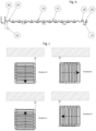
- the downside of the bottom plate 17 contains an array of small tray supports 31 that differ in height from around 1cm to 2cm, to create a modest slope ( ⁇ 1,5%) in the direction of the warm water fluid flow path 21.
- This slope is necessary for situations in which the tray 1 cannot benefit from the slope that is already present in the shower floor, for example in showers where the floor drain is situated in the middle of the shower floor.
- the tray can be arranged on the shower floor in such a way that the direction of the warm water fluid flow path is in line with the slope of the shower floor.
- the tray inlet 28 in which the shower drain water is introduced, and a tray outlet 29, where the cooled-down shower drain water is discharged out of the tray through a cavity 30 .
- the shower drain water is discharged either onto the shower floor or into a discharge pipe 32 that is mounted to the cavity.
- top plate 19 On top of the bottom plate 17 there is a top plate 19 that has two main functions: 1.) to form a solid feet space for a showering person, and 2.) to introduce the (warm) shower water as quickly as possible into the underlying warm water fluid flow path 21 (see figures M,N).
- the top plate is made of one piece and has downwardly directed positioners 33, that are arranged in the direction of the warm water fluid flow path 21 and that rest on top of the meandering heat exchanger tube 18. In this way, the weight of the person standing on top of the top plate is passed onto the heat exchanger tube and forces the heat exchanger tube towards the bottom of the bottom plate, to prevent shower drain water from flowing underneath the heat exchanger tube.
- the positioners are constructed in such a way that the top plate has a slope in the direction opposite to the slope of the warm water fluid flow path.
- the slope of the top plate neutralizes the slope of the warm water fluid flow path and the slope of the shower floor, and adds a slight slope in the opposite direction.
- the slope is carefully chosen (3-5%) in such a way that the tray 1 can be placed directly on top of the floor of most showers without a need for levelling.
- the height of the elevated edge is carefully chosen (0.6 cm - 0.8 cm) to be high enough to prevent the water from running off, while being low enough to prevent foot injuries while stepping onto the top plate.
- In the lowest part of the top plate is a slot-shaped cavity 35 through which the hot shower water is discharged into the underlying warm water fluid flow path.
- the double connection tube 2 is largely encased in a casing or wrap 36, to visually form one piece (see figure O ).
- the encasement stops in the place where the double connection tube enters the tray 1.
- the double connection tube has threaded couplers 37 on all four tube ends, to easily fit the tubes onto the connection device 2 and onto the meandering heat exchanger tube 18.
Landscapes
- Engineering & Computer Science (AREA)
- General Engineering & Computer Science (AREA)
- Physics & Mathematics (AREA)
- Mechanical Engineering (AREA)
- Thermal Sciences (AREA)
- Water Supply & Treatment (AREA)
- Life Sciences & Earth Sciences (AREA)
- Public Health (AREA)
- Hydrology & Water Resources (AREA)
- Health & Medical Sciences (AREA)
- Chemical & Material Sciences (AREA)
- Combustion & Propulsion (AREA)
- Heat-Exchange Devices With Radiators And Conduit Assemblies (AREA)
- Bathtubs, Showers, And Their Attachments (AREA)
- Heat-Pump Type And Storage Water Heaters (AREA)
Claims (15)
- Wärmeaustauschsystem für eine Dusche, umfassendeine Wanne (1), die einen Wärmetauscher (18) mit einen Einlass (24) und einen Auslass (25) umfasst,einem Doppelkanal (2) für die Flüssigkeitsströmung, wobei ein erster Kanal angepasst ist, um in Flüssigkeitsverbindung mit einem Kaltwasserauslass und dem Wärmetauschereinlass (24) zu stehen, und ein zweiter Kanal angepasst ist, um in Flüssigkeitsverbindung mit dem Wärmetauscherauslass (25) und einem Duschhahn zu stehen, undeinem Flüssigkeitsumleiter (3), wobei der Umleiter einen ersten Flüssigkeitsströmungspfad (6) zum Empfangen von kaltem Wasser von dem Kaltwasserauslass und zum Übertragen von kaltem Wasser zu dem Wärmetauschereinlass (24) und einen zweiten Flüssigkeitsströmungspfad (7) zum Empfangen von warmem Wasser von dem Wärmetauscherauslass (25) umfasst, und zum Weiterleiten des warmen Wassers zum Duschhahn und eine Befestigung (10) zur Befestigung an einem Kaltwasserauslass,gekennzeichnet durch der Wärmetauscher (18) der einen mäanderförmigen Flüssigkeitsströmungspfad mit geraden Rohrsegmenten zum Austausch von Wärme von warmem Duschwasser zu kaltem Zuflusswasser umfasst, wobei die geraden Rohrsegmente des Wärmetauschersim Wesentlichen in einer Richtung senkrecht zu warmem Duschwasser verläuft, das durch die Wanne bereitgestellt wird, wobei ein Warmwasserflüssigkeitsströmungspfad (21) vorzugsweise in einem 0,01-4 cm dicken horizontalen Kanal bereitgestellt ist, vorzugsweise einem horizontalen Kanal mit variabler Dicke.
- Wärmeaustauschsystem nach Anspruch 1, umfassend einen Duschhahn, insbesondere wobei der Flüssigkeitsumleiter in den Duschhahn (13) integriert ist.
- Wärmeaustauschsystem nach einem der Ansprüche 1 bis 2, wobei der Flüssigkeitsumleiter (3) einen ersten Flüssigkeitsströmungspfadeinlass (8) umfasst, der mit einem zweiten Flüssigkeitsströmungspfadauslass (9) in Linie liegt.
- Wärmeaustauschsystem nach einem der Ansprüche 1 bis 2, wobei der erste Flüssigkeitsströmungspfad (6) des Umleiters zu einer ersten Seite des Umleiters gerichtet ist und wobei der zweite Flüssigkeitsströmungspfad (7) des Umleiters zu einer zweiten Seite des Umleiters gerichtet ist.
- Wärmeaustauschsystem nach einem der Ansprüche 1 bis 3, wobei der Fixator (10) des Umleiters ein Schraubelement ist.
Beschlag, und wobei der Fixateur um 360 Grad drehbar ist. - Wärmeaustauschsystem nach einem der Ansprüche 1 bis 4, wobei der erste und der zweite Flüssigkeitsströmungspfad (6, 7) nebeneinander angeordnet sind und wobei der erste Flüssigkeitsströmungspfad einen Einlass (8), einen seitlichen Kanal in Flüssigkeitsverbindung mit dem Einlass und einen vertikalen Auslass (11) in Flüssigkeitsverbindung mit dem seitlichen Kanal umfasst und wobei der zweite Flüssigkeitsströmungspfad einen vertikalen Einlass (12), einen seitlichen Kanal in Flüssigkeitsverbindung mit dem Einlass und einen Auslass (9) in Flüssigkeitsverbindung mit dem seitlichen Kanal umfasst, wobei die seitlichen Kanäle vorzugsweise in einem Winkel a, beispielsweise von 30 bis 89 Grad, in Bezug auf den Einlass/Auslass (8, 9) angeordnet sind, insbesondere wobei der Einlass des ersten Fluidströmungswegs zumindest teilweise zwischen dem vertikalen Einlass und dem vertikalen Auslass platziert ist.
- Wärmeaustauschsystem nach einem der Ansprüche 1 bis 6,
wobei die Schale (1) einen Einlass (28) zum Aufnehmen von warmem Duschwasser und einen Auslass (29) zum Ablassen des Duschwassers umfasst. - Wärmeaustauschsystem nach einem der Ansprüche 1 bis 7, wobei der Einlass (24) und der Auslass (25) des Wärmetauschers (18) diagonal angeordnet sind.
- Wärmeaustauschsystem nach einem der Ansprüche 1 bis 8, wobei die Schale (1) eine obere Platte (19), einen Wärmetauscher (18) und eine untere Platte (17) umfasst, vorzugsweise eine abnehmbare obere Platte, untere Platte und einen abnehmbaren Wärmetauscher, wobei der Wärmetauscher vorzugsweise über 5 bis 50 % einer Oberfläche der unteren Platte vorgesehen ist.
- Wärmeaustauschsystem nach einem der Ansprüche 1 bis 9, wobei die Wanne (1) eine Rinne (20) zur Aufnahme des Doppelkanals (2) aufweist, wobei sich mindestens ein Rinneneingang (27) in einer Ecke der Wanne befindet, wo kein Einlass (24) oder Auslass (25) für den Wärmetauscher vorgesehen ist.
- Wärmeaustauschsystem nach einem der Ansprüche 1 bis 10, wobei die Schale (1) Stützen (31) aufweist, die für die Entwässerung sorgen.
- Wärmeaustauschsystem nach einem der Ansprüche 1 bis 11, wobei die Schale (1) Befestigungselemente (23) zum Befestigen des Wärmetauschers (18) an der Bodenplatte (17) aufweist, wobei die Schale vorzugsweise Positionierer (33) umfasst, um den Wärmetauscher nach unten zu drücken, und wobei die Bodenplatte zwischen den Wärmetauschern Bodenplattenmaterial (22) auf über 50-90 % ihrer Oberfläche umfasst, wobei eine Höhe des Bodenplattenmaterials < 100 % einer Höhe des Wärmetauschers neben dem Wärmetauscher beträgt oder fehlt, wo der Wärmetauscher vorgesehen ist, vorzugsweise isolierendes Bodenplattenmaterial, insbesondere
wobei die Bodenstützen (31) für eine Entleerung in Richtung des Bodenauslasses (29) sorgen und wobei die Positionierer (33) für eine Entleerung in Richtung des Bodeneinlasses (28) sorgen. - Wärmeaustauschsystem nach einem der Ansprüche 1 bis 12, wobei der Doppelkanal (2) zumindest teilweise in einem Gehäuse (36) vorgesehen ist.
- Wärmeaustauschsystem nach einem der Ansprüche 1 bis 13, wobei der Doppelkanal (2) mindestens eine Kupplung (37) aufweist, vorzugsweise eine Kupplung mit Gewinde.
- Teilesatz für ein Wärmeaustauschsystem nach einem der Ansprüche 1 bis 14, umfassend eine Wanne mit einem Wärmetauscher (18), gekennzeichnet durch einen mäanderförmigen Flüssigkeitsströmungspfad mit geraden Rohrsegmenten zum Austausch von Wärme von warmem Duschwasser zu kaltem Zuflusswasser zum Austauschen von Wärme von warmem Duschwasser zu kaltem Zuflusswasser, wobei der Wärmetauscher einen Einlass (24) und einen Auslass (25) umfasst, wobei die geraden Rohrsegmente des Wärmetauschers im Wesentlichen in einer Richtung senkrecht zu dem durch die Wanne bereitgestellten warmen Duschwasser verläuft, und mindestens ein weiteres Element, einen Duschhahn, eine Kupplung, eine Duschwandarmatur, einen Umsteller und eine Armatur.
Priority Applications (1)
| Application Number | Priority Date | Filing Date | Title |
|---|---|---|---|
| HRP20250724TT HRP20250724T1 (hr) | 2019-09-18 | 2020-09-01 | Sustav za povrat topline iz odvodne vode tuša i komplet dijelova za takav sustav |
Applications Claiming Priority (2)
| Application Number | Priority Date | Filing Date | Title |
|---|---|---|---|
| NL2023849A NL2023849B1 (en) | 2019-09-18 | 2019-09-18 | System for heat recovery from shower drain water |
| PCT/NL2020/050538 WO2021054821A1 (en) | 2019-09-18 | 2020-09-01 | System for heat recovery from shower drain water |
Publications (3)
| Publication Number | Publication Date |
|---|---|
| EP4031813A1 EP4031813A1 (de) | 2022-07-27 |
| EP4031813B1 true EP4031813B1 (de) | 2025-03-19 |
| EP4031813C0 EP4031813C0 (de) | 2025-03-19 |
Family
ID=68343421
Family Applications (1)
| Application Number | Title | Priority Date | Filing Date |
|---|---|---|---|
| EP20767886.3A Active EP4031813B1 (de) | 2019-09-18 | 2020-09-01 | System zur wärmerückgewinnung aus duschabflusswasser und teilesatz für ein solches system |
Country Status (5)
| Country | Link |
|---|---|
| EP (1) | EP4031813B1 (de) |
| HR (1) | HRP20250724T1 (de) |
| NL (1) | NL2023849B1 (de) |
| PL (1) | PL4031813T3 (de) |
| WO (1) | WO2021054821A1 (de) |
Families Citing this family (2)
| Publication number | Priority date | Publication date | Assignee | Title |
|---|---|---|---|---|
| AU2023313123A1 (en) | 2022-07-29 | 2025-02-20 | Zypho, Sa | Heat recovery system |
| GB2624235A (en) * | 2022-11-11 | 2024-05-15 | Kohler Mira Ltd | Plumbing or Ablutionary System |
Family Cites Families (11)
| Publication number | Priority date | Publication date | Assignee | Title |
|---|---|---|---|---|
| DD252739A3 (de) * | 1985-10-30 | 1987-12-30 | Bauakademie Ddr | Duscheinrichtung zur abwasserwaermenutzung |
| GB2416829B (en) * | 2004-07-29 | 2009-04-08 | A K Ind Ltd | Heat exchanger assembly and appliance including heat exchanger |
| US7849530B2 (en) * | 2005-10-25 | 2010-12-14 | Craig Hendricks | Waste-water heat recovery system |
| WO2010084620A1 (ja) * | 2009-01-26 | 2010-07-29 | Sumi Noriaki | 熱交換システム |
| CH700393A1 (de) | 2009-02-06 | 2010-08-13 | Creaholic Sa | Wärmetauscher. |
| HK1128387A2 (zh) * | 2009-07-07 | 2009-10-23 | 源创者科技有限公司 | 热能回收装置以及具有其的热能回收系统 |
| CN102996958B (zh) | 2012-10-15 | 2015-08-19 | 张斌 | 一种管道分流串联装置 |
| CN102997717B (zh) * | 2012-10-15 | 2014-06-18 | 张斌 | 一种驻水式高效回收利用浴后热水热能的淋浴装置 |
| CH709194A2 (de) | 2014-01-17 | 2015-07-31 | Joulia Ag | Wärmetauscher für eine Dusche oder Badewanne. |
| WO2017077462A1 (pt) | 2015-11-02 | 2017-05-11 | Eidt - Engenharia, Inovação E Desenvolvimento Tecnológico, Sa | Recuperador de calor |
| CN107387808A (zh) * | 2016-05-17 | 2017-11-24 | 赵海慧 | 一种可外接水处理装置的混水阀 |
-
2019
- 2019-09-18 NL NL2023849A patent/NL2023849B1/en active
-
2020
- 2020-09-01 EP EP20767886.3A patent/EP4031813B1/de active Active
- 2020-09-01 PL PL20767886.3T patent/PL4031813T3/pl unknown
- 2020-09-01 HR HRP20250724TT patent/HRP20250724T1/hr unknown
- 2020-09-01 WO PCT/NL2020/050538 patent/WO2021054821A1/en not_active Ceased
Also Published As
| Publication number | Publication date |
|---|---|
| WO2021054821A1 (en) | 2021-03-25 |
| EP4031813A1 (de) | 2022-07-27 |
| EP4031813C0 (de) | 2025-03-19 |
| PL4031813T3 (pl) | 2025-12-22 |
| HRP20250724T1 (hr) | 2025-08-29 |
| NL2023849B1 (en) | 2021-05-25 |
Similar Documents
| Publication | Publication Date | Title |
|---|---|---|
| US8104532B2 (en) | Shower heat exchanger with clog-removable drain | |
| EP3149253B1 (de) | Bodenablauf | |
| US7849530B2 (en) | Waste-water heat recovery system | |
| CN102216716B (zh) | 热交换装置 | |
| EP4031813B1 (de) | System zur wärmerückgewinnung aus duschabflusswasser und teilesatz für ein solches system | |
| WO2006045153A1 (en) | Heat recovery system | |
| US20210341154A1 (en) | Hot water supply system | |
| US20170038158A1 (en) | Heat exchanger and a system for recovery of thermal energy from waste water | |
| EP3440971A1 (de) | Effiziente duschwanne mit einer in die oberfläche integrierten, statischen, zugänglichen und leicht zu reinigenden wärmerückgewinnungsvorrichtung | |
| CA2775456C (en) | Shower heat exchanger with clog-removable drain | |
| CA2621626A1 (en) | Waste water drain heat exchanger preheating cold water supply to a thermostatic control valve | |
| WO2010140138A2 (en) | Heat recovery system and thermo-syphon thereof | |
| ES2638037B1 (es) | Plato de ducha ahorrador de agua caliente | |
| KR200483305Y1 (ko) | 유로전환 기능을 갖는 접이식 세면대 | |
| KR101374077B1 (ko) | 수돗물 절수장치 | |
| CN203561232U (zh) | 一种洗漱盆式散热器 | |
| SE2350865A1 (en) | A heat exchanger for a drain compartment, and a heat exchanger system | |
| CN209926926U (zh) | 一种利用淋浴废水预热给水的节能装置 | |
| CN109654279B (zh) | 一种多功能智能控制龙头系统 | |
| WO2024217608A1 (en) | Device for heat recovery from waste water of a building | |
| CZ37117U1 (cs) | Zařízení pro zpětné získávání tepla z odpadní vody stavebního objektu | |
| KR200431836Y1 (ko) | 냉온수 배관시스템 | |
| JP2004036207A (ja) | 湯水抜栓 | |
| GB2530660A (en) | Heat recovery for grey water systems | |
| CZ23939U1 (cs) | Sprchová vanička |
Legal Events
| Date | Code | Title | Description |
|---|---|---|---|
| REG | Reference to a national code |
Ref country code: HR Ref legal event code: TUEP Ref document number: P20250724T Country of ref document: HR |
|
| STAA | Information on the status of an ep patent application or granted ep patent |
Free format text: STATUS: UNKNOWN |
|
| STAA | Information on the status of an ep patent application or granted ep patent |
Free format text: STATUS: THE INTERNATIONAL PUBLICATION HAS BEEN MADE |
|
| PUAI | Public reference made under article 153(3) epc to a published international application that has entered the european phase |
Free format text: ORIGINAL CODE: 0009012 |
|
| STAA | Information on the status of an ep patent application or granted ep patent |
Free format text: STATUS: REQUEST FOR EXAMINATION WAS MADE |
|
| 17P | Request for examination filed |
Effective date: 20220321 |
|
| AK | Designated contracting states |
Kind code of ref document: A1 Designated state(s): AL AT BE BG CH CY CZ DE DK EE ES FI FR GB GR HR HU IE IS IT LI LT LU LV MC MK MT NL NO PL PT RO RS SE SI SK SM TR |
|
| RAP1 | Party data changed (applicant data changed or rights of an application transferred) |
Owner name: SCHIETECAT, TOMAS JOHAN Owner name: BERGMANS, BART JOSEPH CHRISTIAAN Owner name: SANURA B.V. |
|
| DAV | Request for validation of the european patent (deleted) | ||
| DAX | Request for extension of the european patent (deleted) | ||
| GRAP | Despatch of communication of intention to grant a patent |
Free format text: ORIGINAL CODE: EPIDOSNIGR1 |
|
| STAA | Information on the status of an ep patent application or granted ep patent |
Free format text: STATUS: GRANT OF PATENT IS INTENDED |
|
| INTG | Intention to grant announced |
Effective date: 20241025 |
|
| GRAS | Grant fee paid |
Free format text: ORIGINAL CODE: EPIDOSNIGR3 |
|
| GRAA | (expected) grant |
Free format text: ORIGINAL CODE: 0009210 |
|
| STAA | Information on the status of an ep patent application or granted ep patent |
Free format text: STATUS: THE PATENT HAS BEEN GRANTED |
|
| AK | Designated contracting states |
Kind code of ref document: B1 Designated state(s): AL AT BE BG CH CY CZ DE DK EE ES FI FR GB GR HR HU IE IS IT LI LT LU LV MC MK MT NL NO PL PT RO RS SE SI SK SM TR |
|
| REG | Reference to a national code |
Ref country code: GB Ref legal event code: FG4D |
|
| REG | Reference to a national code |
Ref country code: CH Ref legal event code: EP |
|
| REG | Reference to a national code |
Ref country code: IE Ref legal event code: FG4D |
|
| REG | Reference to a national code |
Ref country code: DE Ref legal event code: R096 Ref document number: 602020047956 Country of ref document: DE |
|
| U01 | Request for unitary effect filed |
Effective date: 20250415 |
|
| U07 | Unitary effect registered |
Designated state(s): AT BE BG DE DK EE FI FR IT LT LU LV MT NL PT RO SE SI Effective date: 20250428 |
|
| PG25 | Lapsed in a contracting state [announced via postgrant information from national office to epo] |
Ref country code: RS Free format text: LAPSE BECAUSE OF FAILURE TO SUBMIT A TRANSLATION OF THE DESCRIPTION OR TO PAY THE FEE WITHIN THE PRESCRIBED TIME-LIMIT Effective date: 20250619 |
|
| PG25 | Lapsed in a contracting state [announced via postgrant information from national office to epo] |
Ref country code: NO Free format text: LAPSE BECAUSE OF FAILURE TO SUBMIT A TRANSLATION OF THE DESCRIPTION OR TO PAY THE FEE WITHIN THE PRESCRIBED TIME-LIMIT Effective date: 20250619 |
|
| PG25 | Lapsed in a contracting state [announced via postgrant information from national office to epo] |
Ref country code: GR Free format text: LAPSE BECAUSE OF FAILURE TO SUBMIT A TRANSLATION OF THE DESCRIPTION OR TO PAY THE FEE WITHIN THE PRESCRIBED TIME-LIMIT Effective date: 20250620 |
|
| RAP2 | Party data changed (patent owner data changed or rights of a patent transferred) |
Owner name: SANURA B.V. |
|
| U1K | Transfer of rights of the unitary patent after the registration of the unitary effect |
Owner name: SANURA B.V.; NL |
|
| REG | Reference to a national code |
Ref country code: HR Ref legal event code: PPPP Ref document number: P20250724 Country of ref document: HR Owner name: SANURA B.V., NL |
|
| REG | Reference to a national code |
Ref country code: HR Ref legal event code: T1PR Ref document number: P20250724 Country of ref document: HR |
|
| REG | Reference to a national code |
Ref country code: HR Ref legal event code: ODRP Ref document number: P20250724 Country of ref document: HR Payment date: 20250826 Year of fee payment: 6 |
|
| REG | Reference to a national code |
Ref country code: CH Ref legal event code: U11 Free format text: ST27 STATUS EVENT CODE: U-0-0-U10-U11 (AS PROVIDED BY THE NATIONAL OFFICE) Effective date: 20251001 |
|
| PG25 | Lapsed in a contracting state [announced via postgrant information from national office to epo] |
Ref country code: SM Free format text: LAPSE BECAUSE OF FAILURE TO SUBMIT A TRANSLATION OF THE DESCRIPTION OR TO PAY THE FEE WITHIN THE PRESCRIBED TIME-LIMIT Effective date: 20250319 |
|
| U20 | Renewal fee for the european patent with unitary effect paid |
Year of fee payment: 6 Effective date: 20250902 |
|
| PG25 | Lapsed in a contracting state [announced via postgrant information from national office to epo] |
Ref country code: ES Free format text: LAPSE BECAUSE OF FAILURE TO SUBMIT A TRANSLATION OF THE DESCRIPTION OR TO PAY THE FEE WITHIN THE PRESCRIBED TIME-LIMIT Effective date: 20250319 |
|
| PGFP | Annual fee paid to national office [announced via postgrant information from national office to epo] |
Ref country code: GB Payment date: 20250929 Year of fee payment: 6 |
|
| PGFP | Annual fee paid to national office [announced via postgrant information from national office to epo] |
Ref country code: HR Payment date: 20250826 Year of fee payment: 6 |
|
| PG25 | Lapsed in a contracting state [announced via postgrant information from national office to epo] |
Ref country code: CZ Free format text: LAPSE BECAUSE OF FAILURE TO SUBMIT A TRANSLATION OF THE DESCRIPTION OR TO PAY THE FEE WITHIN THE PRESCRIBED TIME-LIMIT Effective date: 20250319 |
|
| PGFP | Annual fee paid to national office [announced via postgrant information from national office to epo] |
Ref country code: IE Payment date: 20250929 Year of fee payment: 6 |
|
| PG25 | Lapsed in a contracting state [announced via postgrant information from national office to epo] |
Ref country code: SK Free format text: LAPSE BECAUSE OF FAILURE TO SUBMIT A TRANSLATION OF THE DESCRIPTION OR TO PAY THE FEE WITHIN THE PRESCRIBED TIME-LIMIT Effective date: 20250319 |
|
| PG25 | Lapsed in a contracting state [announced via postgrant information from national office to epo] |
Ref country code: IS Free format text: LAPSE BECAUSE OF FAILURE TO SUBMIT A TRANSLATION OF THE DESCRIPTION OR TO PAY THE FEE WITHIN THE PRESCRIBED TIME-LIMIT Effective date: 20250719 |
|
| PGFP | Annual fee paid to national office [announced via postgrant information from national office to epo] |
Ref country code: CH Payment date: 20251001 Year of fee payment: 6 |
|
| PGFP | Annual fee paid to national office [announced via postgrant information from national office to epo] |
Ref country code: PL Payment date: 20250618 Year of fee payment: 6 |
|
| PLBE | No opposition filed within time limit |
Free format text: ORIGINAL CODE: 0009261 |
|
| STAA | Information on the status of an ep patent application or granted ep patent |
Free format text: STATUS: NO OPPOSITION FILED WITHIN TIME LIMIT |
|
| REG | Reference to a national code |
Ref country code: CH Ref legal event code: L10 Free format text: ST27 STATUS EVENT CODE: U-0-0-L10-L00 (AS PROVIDED BY THE NATIONAL OFFICE) Effective date: 20260128 |