EP4031769B1 - Kitchen appliance apparatus - Google Patents
Kitchen appliance apparatus Download PDFInfo
- Publication number
- EP4031769B1 EP4031769B1 EP20775738.6A EP20775738A EP4031769B1 EP 4031769 B1 EP4031769 B1 EP 4031769B1 EP 20775738 A EP20775738 A EP 20775738A EP 4031769 B1 EP4031769 B1 EP 4031769B1
- Authority
- EP
- European Patent Office
- Prior art keywords
- pump
- primary port
- moisture
- accessory
- housing
- Prior art date
- Legal status (The legal status is an assumption and is not a legal conclusion. Google has not performed a legal analysis and makes no representation as to the accuracy of the status listed.)
- Active
Links
- 239000012530 fluid Substances 0.000 claims description 73
- 239000007788 liquid Substances 0.000 claims description 44
- 238000001514 detection method Methods 0.000 claims description 38
- 230000008878 coupling Effects 0.000 claims description 18
- 238000010168 coupling process Methods 0.000 claims description 18
- 238000005859 coupling reaction Methods 0.000 claims description 18
- 238000011144 upstream manufacturing Methods 0.000 claims description 15
- 230000001681 protective effect Effects 0.000 claims description 14
- 239000011358 absorbing material Substances 0.000 claims description 10
- 238000007664 blowing Methods 0.000 claims description 7
- 238000007789 sealing Methods 0.000 claims description 7
- 238000004891 communication Methods 0.000 claims description 3
- 235000013305 food Nutrition 0.000 description 21
- 239000000463 material Substances 0.000 description 7
- CURLTUGMZLYLDI-UHFFFAOYSA-N Carbon dioxide Chemical compound O=C=O CURLTUGMZLYLDI-UHFFFAOYSA-N 0.000 description 6
- 239000006260 foam Substances 0.000 description 5
- 238000002347 injection Methods 0.000 description 4
- 239000007924 injection Substances 0.000 description 4
- 229910002092 carbon dioxide Inorganic materials 0.000 description 3
- 239000001569 carbon dioxide Substances 0.000 description 3
- 239000002245 particle Substances 0.000 description 3
- 230000002411 adverse Effects 0.000 description 2
- 230000005540 biological transmission Effects 0.000 description 2
- 238000004140 cleaning Methods 0.000 description 2
- 238000011109 contamination Methods 0.000 description 2
- 238000010411 cooking Methods 0.000 description 2
- 235000013372 meat Nutrition 0.000 description 2
- 239000012528 membrane Substances 0.000 description 2
- 238000010295 mobile communication Methods 0.000 description 2
- 230000003287 optical effect Effects 0.000 description 2
- 230000008901 benefit Effects 0.000 description 1
- 238000006073 displacement reaction Methods 0.000 description 1
- 239000000428 dust Substances 0.000 description 1
- 230000000694 effects Effects 0.000 description 1
- 239000011521 glass Substances 0.000 description 1
- 238000009434 installation Methods 0.000 description 1
- 235000015090 marinades Nutrition 0.000 description 1
- 230000007246 mechanism Effects 0.000 description 1
- 238000000034 method Methods 0.000 description 1
- 239000008267 milk Substances 0.000 description 1
- 210000004080 milk Anatomy 0.000 description 1
- 235000013336 milk Nutrition 0.000 description 1
- 235000014594 pastries Nutrition 0.000 description 1
- 230000008569 process Effects 0.000 description 1
- 238000005086 pumping Methods 0.000 description 1
- 239000004576 sand Substances 0.000 description 1
- 229920006395 saturated elastomer Polymers 0.000 description 1
- 235000015067 sauces Nutrition 0.000 description 1
Images


Classifications
-
- B—PERFORMING OPERATIONS; TRANSPORTING
- B01—PHYSICAL OR CHEMICAL PROCESSES OR APPARATUS IN GENERAL
- B01F—MIXING, e.g. DISSOLVING, EMULSIFYING OR DISPERSING
- B01F33/00—Other mixers; Mixing plants; Combinations of mixers
- B01F33/40—Mixers using gas or liquid agitation, e.g. with air supply tubes
-
- F—MECHANICAL ENGINEERING; LIGHTING; HEATING; WEAPONS; BLASTING
- F04—POSITIVE - DISPLACEMENT MACHINES FOR LIQUIDS; PUMPS FOR LIQUIDS OR ELASTIC FLUIDS
- F04B—POSITIVE-DISPLACEMENT MACHINES FOR LIQUIDS; PUMPS
- F04B49/00—Control, e.g. of pump delivery, or pump pressure of, or safety measures for, machines, pumps, or pumping installations, not otherwise provided for, or of interest apart from, groups F04B1/00 - F04B47/00
- F04B49/22—Control, e.g. of pump delivery, or pump pressure of, or safety measures for, machines, pumps, or pumping installations, not otherwise provided for, or of interest apart from, groups F04B1/00 - F04B47/00 by means of valves
-
- B—PERFORMING OPERATIONS; TRANSPORTING
- B01—PHYSICAL OR CHEMICAL PROCESSES OR APPARATUS IN GENERAL
- B01F—MIXING, e.g. DISSOLVING, EMULSIFYING OR DISPERSING
- B01F23/00—Mixing according to the phases to be mixed, e.g. dispersing or emulsifying
- B01F23/20—Mixing gases with liquids
- B01F23/23—Mixing gases with liquids by introducing gases into liquid media, e.g. for producing aerated liquids
- B01F23/235—Mixing gases with liquids by introducing gases into liquid media, e.g. for producing aerated liquids for making foam
-
- B—PERFORMING OPERATIONS; TRANSPORTING
- B01—PHYSICAL OR CHEMICAL PROCESSES OR APPARATUS IN GENERAL
- B01F—MIXING, e.g. DISSOLVING, EMULSIFYING OR DISPERSING
- B01F23/00—Mixing according to the phases to be mixed, e.g. dispersing or emulsifying
- B01F23/20—Mixing gases with liquids
- B01F23/23—Mixing gases with liquids by introducing gases into liquid media, e.g. for producing aerated liquids
- B01F23/236—Mixing gases with liquids by introducing gases into liquid media, e.g. for producing aerated liquids specially adapted for aerating or carbonating beverages
- B01F23/2361—Mixing gases with liquids by introducing gases into liquid media, e.g. for producing aerated liquids specially adapted for aerating or carbonating beverages within small containers, e.g. within bottles
-
- B—PERFORMING OPERATIONS; TRANSPORTING
- B01—PHYSICAL OR CHEMICAL PROCESSES OR APPARATUS IN GENERAL
- B01F—MIXING, e.g. DISSOLVING, EMULSIFYING OR DISPERSING
- B01F2101/00—Mixing characterised by the nature of the mixed materials or by the application field
- B01F2101/06—Mixing of food ingredients
- B01F2101/07—Mixing ingredients into milk or cream, e.g. aerating
-
- B—PERFORMING OPERATIONS; TRANSPORTING
- B01—PHYSICAL OR CHEMICAL PROCESSES OR APPARATUS IN GENERAL
- B01F—MIXING, e.g. DISSOLVING, EMULSIFYING OR DISPERSING
- B01F2101/00—Mixing characterised by the nature of the mixed materials or by the application field
- B01F2101/06—Mixing of food ingredients
- B01F2101/16—Mixing wine or other alcoholic beverages; Mixing ingredients thereof
- B01F2101/17—Aeration of wine
Definitions
- the invention relates to an apparatus for using air in the kitchen.
- An apparatus for using air in the kitchen is known.
- an apparatus to automatically aerate wine in a carafe or glass is known.
- an apparatus having a chamber for conserving food and an integrated vacuum pump vacuums the chamber such that the food contained in the chamber can be longer conserved.
- the use of air in the kitchen can be helpful for vacuuming a bowl or a tray or a jar or a bag in which food can be stored and/or marinated.
- air can be used for aerating wine or for making foam of hot milk.
- US6832634B1 discloses a system for carbonating a liquid with carbon dioxide gas comprising a pressurized source of carbon dioxide gas, a user-operable three-way valve system having a first, a second, and a third orifice providing a first, a second and a third valve state, which in the first state connects the first orifice with the second orifice, in the second state connects the second orifice with the third orifice, and in the third state closes internal passage between all orifices, the valve system connected from the first orifice and a conduit to the pressurized source of carbon dioxide gas, and a closure assembly having an interface to a nozzle of a container for liquid and an orifice connected through a conduit to the second orifice of the three way valve system.
- the invention provides for an apparatus according to claim 1.
- the pump In a first pump mode, the pump operates in suction mode. In a second pump mode, the pump operates in blowing mode, and in the third pump mode, the pump operates in alternating mode.
- the apparatus can thus be used in the first mode, that can be used for vacuuming, for example, a coupled accessory, such as a jar or a bag or a pot or a tray or any other container for storing food.
- the apparatus can also be used in a second mode, that can be used for example, for making foam or aerating etc.
- the apparatus can also be used in a third mode in which it can alternatingly suck air out of, for example, a coupled accessory, and blow air into the coupled accessory, e.g. for marinating food enclosed in the accessory.
- a compact and versatile apparatus can be obtained that allows the easy use of air in the kitchen for various applications.
- the apparatus further comprises a control unit that is configured for controlling the operation of the three-way valves depending on the pump mode.
- a control unit that is configured for controlling the operation of the three-way valves depending on the pump mode.
- the control unit may be provided on a printed circuit board arranged inside of the housing of the apparatus, forming part of the pump system.
- the pressure in the pump system can be monitored.
- the pump system when the pump system is in the first mode, it can be monitored whether a negative pressure is being built up in an accessory coupled to the primary port and out of which air is being pumped.
- the pressure sensor can monitor the positive pressure built up by the pump in the second mode for blowing air out of the primary port.
- the pressure sensor in the third mode, can be used to monitor the difference between negative and positive pressure.
- a negative pressure or an negative pressure or sometimes called vacuum is considered to be a pressure below the atmospheric pressure.
- a positive pressure is considered to be a pressure above the atmospheric pressure.
- the protective film By arranging a protective film in the primary port channel that connects the primary port with the first three-way valve, wherein the protective film is arranged to allow air pass through and liquid not, at least the three-way valve can be protected from moisture ingress.
- the moisture, and/or any other dirt is being accumulated by the film.
- the protective film is arranged between the primary port and the pressure sensor, as to protect the pressure sensor from moisture and/or dirt ingress as well.
- the primary port is arranged for connection to an accessory.
- the accessory can for example be a food container that is coupled to the primary port, or can be a hose engaged to the primary port, the hose itself may then be arranged at a free end thereof for connection to the accessory.
- the primary port is preferably arranged in the housing, more preferably in a wall of the housing, as to form an interface between the pump system inside of the housing, and the outside of the housing.
- the primary port may for example be an opening in the housing through which the hose can be engaged, wherein the hose at one end is arranged for, direct or indirect, connection to the first three way-valve and at its other free end is provided with a coupling element for coupling with an accessory.
- the primary port can be a coupling element to which an accessory can be directly coupled.
- the primary port provides for the interface with the pump system and an accessory or a coupling element outside of the pump system.
- the primary port may then be configured inside of the housing and the connection may be provided by a hose that at one end is connected with the pump system and at another end is provided with a coupling element for connection to an accessory.
- the secondary port is preferably arranged in the housing, more preferably in a wall of the housing, to form an interface with the pump system inside of the housing and the environment outside of the housing.
- the secondary port is in particular arranged to form a fluid connection with the environment outside of the housing, such that air can be blown out via the secondary port when the pump system is in the first mode and air can be sucked in via the secondary port when the pump system is in the second mode, as well as in the alternating mode.
- the pump system further comprises a printed circuit board to which the three-way valves are connectable.
- the three-way valves in particular the three-way solenoid valves, may be directly connectable to the printed circuit board, or may be indirectly connectable to the printed circuit board.
- the three-way solenoid valves are indirectly connectable to the printed circuit board, wherein the solenoid valves are mounted on a support and the support is mountable on the printed circuit board.
- an indirect connection with the printed circuit board can be established allowing a compact arrangement of the valves inside of the housing of the apparatus.
- the solenoid valves via a support to the printed circuit board, the system may be relatively easy to assemble.
- the valves are mounted to one side of the support and the other side of the support is provided with recesses for forming a channel connection with one of the valves or the pump.
- the support is mounted to the printed circuit board, the recesses are closed by the printed circuit board to form a channel through which the air that is being pumped can flow.
- Part of the channels of the pump system can thus be partially integrated in the support and upon installation a channel can be formed in which the recesses are closed by the printed circuit board.
- the support is also used to form a fluid connection between the valves and/or the pump providing for a relatively compact build-up of the pump system.
- the support is arranged as a manifold for multiple fluid connections.
- a sealing member is provided between the support and the printed circuit board to seal off the channels thus formed.
- One of the recesses in the support may be provided with an arrangement for a pressure sensor, e.g. with a seat in which a pressure membrane can be held.
- the pressure sensor may thus be arranged in the thus formed channel. In that case, the sealing member leaves the pressure sensor free.
- the fluid connections between the valves and/or the pump and/or the primary or secondary port are advantageously provided as flexible hoses arranged inside of the housing.
- the flexible hoses provide for an easy to assemble and relatively cost-effective fluid connection in the pump system, and can be relatively easy folded inside of the housing.
- a locking guide is provided through which at least one of the hoses is guided, in particular the hoses downstream of the pump. By providing such a locking guide, assembly of the hoses inside of the housing and connection of the hoses to the support becomes easier.
- the locking guide can be provided with at least two openings through which a hose can be inserted such that the hose at one end is inserted through such an opening and at another end as well.
- Both ends of the hose may then extend at one side of the locking guide.
- the locking guide advantageously is arranged at the side of the support opposite the recesses-side. As such, by mounting the locking guide onto the support and by tightening the locking guide to the support, the hoses are automatically connected to the associated openings in the support, and thus, a tight fit can be obtained.
- the locking guide is in particular suitable for hoses that are subject to a positive pressure. Hoses that are subject to a negative pressure may form a tight fit due to the negative pressure during use.
- control unit is provided on the same printed circuit board as the three-way valves are connectable to. As such, an even more compact arrangement can be provided, and the pump system can be operational using a single printed circuit board.
- the apparatus may be provided with a user interface, that is in operational communication with the control unit.
- the user interface is directly provided on the printed circuit board, in particular the electronic components of the user interface are directly provided on the printed circuit board, while the components that are configured to be in contact with the user are preferably provided on a wall of the housing.
- the user interface can comprise touch buttons that are configured for contact with the user, namely the user contacts or presses the area on the wall of the housing that is dedicated to that end. Below such a contact area, typically the buttons are provided that, preferably, may or, alternatively, may not be directly provided on the printed circuit board.
- the user interface can be a touch screen, display, panel etc.
- the user interface may be provided on a mobile communications device, in particular onto a smart mobile communications device, such as a smart phone, tablet or computer that is in wireless communication with the control unit.
- a smart mobile communications device such as a smart phone, tablet or computer that is in wireless communication with the control unit.
- the user contact area of the user interface may be provided at top side of the housing with the printed circuit board positioned immediately beneath it, such that the contact area can be in direct contact with the buttons provided on the printed circuit board.
- vibrations and/or noise initiated by the pump may be obviated or at least limited from being transmitted to the housing.
- the apparatus might start moving during operation of the pump, e.g. on a table top or a kitchen top and/or it may be obviated that the housing is vibrating itself.
- the lifetime of the housing may be increased.
- the pump is also supported independently of other components of the pump system, such as the printed circuit board and/or the valves.
- the housing may comprise a base part and an upper part, wherein the pump is resiliently supported to the base part.
- the upper part of the housing can be independent from the base part, and can remain free of vibrations from the pump.
- the pump system is provided with a moisture detection element in a channel upstream of the pump.
- Moisture in the pump system may adversely affect the functioning of the pump, so an early detection may be advantageous for the functioning of the pump system.
- the working of the pump may be stopped to allow the moisture to be removed from the pump system, or, a moisture removal element may be in place to prevent moisture from harming the pump.
- the moisture detection element may comprise an electrical moisture sensor e.g. comprising two electrical contact points that are arranged in a channel upstream of the pump, preferably in a channel between the primary port and the first three-way valve.
- the electrical contact points of the electrical moisture sensor When there is moisture in the air passing by the electrical contact points of the electrical moisture sensor, the electrical contact points are brought in electrical contact resulting in a voltage drop. Such a voltage drop can be detected and be signaled that moisture is detected. Such a detection signal may then e.g. be transmitted to the control unit that may shut down the pump or may bring the pump into the second mode to blow the moisture out of the channel.
- the moisture detection element may comprise a moisture absorbing material arranged in a channel upstream of the pump, preferably in a channel between the primary port and the first three-way valve.
- the moisture absorbing material may e.g. be a foam in which the moisture can be captured, once the foam is saturated a detection signal may be sent to the control unit to shut down the pump until the moisture absorbing material is replaced.
- the moisture absorbing material for example can be a material that swells when it comes in contact with moisture and thus may block the channel, thereby the working of the pump may be stopped.
- the moisture detection element may comprise and optical sensor detecting fluid droplets in a channel upstream of the pump.
- the optical sensor may see fluid passing by in the channel upstream of the pump, and may signal detection of any fluid.
- the moisture detection element may comprise an internal reservoir that is fluidly connectable to a channel upstream of the pump, preferably connectable to a channel between the primary port and the first three-way valve.
- the internal reservoir may thus capture any moisture of fluid entering the pump system via the primary port, e.g. until the internal reservoir is filled.
- the internal reservoir holds any liquid entering the internal reservoir between moisture detection and halting of the pump.
- a moisture detection sensor may be present, e.g. in the channel upstream of the internal reservoir and/or in the internal reservoir itself. Then, a detection signal may be sent such that the internal reservoir can be emptied.
- the internal reservoir preferably is provided in the housing and accessible for the user, such that the user can access it to remove it from the housing and empty it.
- the internal reservoir may form part of the pump system and of a moisture detection element for obviating moisture to adversely effect the functioning of the pump.
- the size of the internal reservoir may thus be constrained by the available space inside of the housing, but is preferably at least as large as twice the volume displacement of air and/or liquid in the time between detection and the halting of the first pump mode.
- the functioning of the pump in the first pump mode is stopped upon detection of moisture by the moisture detection sensor and/or the internal reservoir. Then, the pump may continue working in the second pump mode in an attempt to blow the channel clean of moisture.
- the pump may continue working in the second pump mode until the user actively stops the working of pump.
- the pump may then only restart when the internal reservoir has been emptied.
- the user may then restart the pump, and/or it can be checked by the moisture detection element that no moisture is detected and thus, effectively, the internal reservoir was emptied before restarting the pump.
- the moisture detection element may comprise an external container that is fluidly connectable with the primary port.
- the external container is positioned outside of the housing and is separate from the housing.
- the external container advantageously has a first opening for connection with the primary port and has a second opening for connection with an accessory.
- the external container is positioned between the accessory and the primary port to capture any moisture that is being sucked in from the accessory.
- the external container is provided with a third opening that is in fluid connection with the environment outside and can be closed so a negative pressure can be created in the external container, and the accessory coupled to it, when the pump is in the first mode, or an positive pressure can be created in the external container, and the accessory coupled to it, when the pump is in the second mode.
- the third opening is open, the external container is in fluid connection with the environment outside of the external container.
- an accessory may be provided wherein the accessory comprises an external container.
- the accessory advantageously has a first opening for connection with the primary port.
- the accessory advantageously has a second opening fluidly connecting the first opening to the environment.
- the accessory advantageously has a third opening fluidly connecting the external container to the environment, which may be opened or closed to provide a fluid connection with the environment or with the second opening respectively.
- the accessory may be embodied as a fluid injector wherein the external container is integrated to the injector. So, instead of providing a separate external container for receiving fluid, the container is integrated to the injector.
- a pressure created by the pump may be transferred to an external container by a pressure transferring element.
- the pressure transferring element can for example be a piston.
- the accessory as an injector with integrated container may comprise a piston that is biased towards a first position. When the injector is connected to the primary port of the apparatus, the apparatus may provide sufficient pressure to overcome the biasing force of the piston to move the piston to a second position towards the second opening of the accessory, typically the outlet or injection needle.
- the volume of the receiving container is larger than the volume of the receiving container in the second position.
- the piston In the first position of the piston, the piston is biased towards the first opening of the injector accessory.
- fluid or liquid can be sucked up with the injector into the container, but can also be pumped out of the container of the injector.
- liquid can be sucked up from, e.g. a receptacle, into the integrated container of the injector, and/or liquid received in the integrated container of the injector can be ejected out of the injector into food or can be sprayed out of the injector over food.
- a system comprising an apparatus and an accessory that is fluidly connectable with the primary port.
- the accessory is connectable to the primary port via an external container having a first opening fluidly connectable to the primary port of the apparatus, and having a second opening that is fluidly connectable to the accessory, which may be a hose. Liquid or moisture accidentally, or deliberately, present in the air flow blown out or sucked in via the second opening, can be received in the external container. By providing such an external container, it may be avoided or limited that liquid enters into the pump system.
- the external container may be provided with a third opening for connection with the environment outside the external container, wherein opening or closing of the third opening provides for creating a negative pressure or a positive pressure in the external container depending on the operational mode of the pump system.
- liquid from the external container can be removed from the container via the second opening of the container and the accessory.
- liquid can be sucked up via the accessory, which may be a simple hose, to be received in the container.
- the accessory connectable to the external container can be provided as a fluid injector.
- the fluid injector may facilitate injection of liquid into food, such as meat, or may facilitate distribution of liquid over food. Also, the fluid injector may allow more easy sucking up of liquid.
- the accessory may be provided as a fluid injector to which the container for receiving liquid is integrated.
- the fluid injector may comprise a piston chamber receiving a piston therein, such that the piston divides the chamber in a first chamber in fluid connection with the first opening of the accessory, and a second chamber in fluid connection with a second opening, namely the outlet or injection needle, of the accessory.
- the second chamber is then embodied as the container for receiving liquid therein.
- FIG. 1 gives a schematic representation of a pump system 100 for use in a kitchen appliance apparatus for using air in the kitchen.
- the pump system 100 comprises a single direction air pump 101 having an inlet 102 and an outlet 103.
- the pump system 100 further comprises a first three-way valve 104 and a second three-way valve 105.
- the first three-way valve 104 is fluidly connected to the inlet 102 of the pump 101.
- the second three-way valve 105 is fluidly connected to the outlet 103 of the pump 101.
- the pump system 100 comprises a primary port 106 and a secondary port 107.
- the primary port 106 is fluidly connected with the first three-way valve 104 and the secondary port 107 is fluidly connected with the second three-way valve 105.
- a channel 108 is provided to establish the fluid connection, referred to as the primary port channel 108.
- a channel 109 is provided to establish the fluid connection, referred to as the primary port channel 109.
- a second arm 104b of the first three-way valve 104 is via a channel 110, referred to as the first inlet channel 110, fluidly connected to the inlet 102 of the pump 101.
- a second arm 105b of the first three-way valve 105 is via a second inlet channel 111 fluidly connected to the inlet 102 of the pump 101.
- a third arm 104c of the first three-way valve 104 is via a channel 112, referred to as a first outlet channel 112, fluidly connected to the outlet 103 of the pump 101.
- a third arm 105c of the second three-way valve 105 is via a channel 113, referred to as a second outlet channel 113, fluidly connected to the outlet 103 of the pump 101.
- the first three-way valve 104 is fluidly connected to the primary port 106, the inlet 102 of the pump 101, and the outlet 103 of the pump 101.
- the second three way-valve 105 is fluidly connected with the secondary port 107, the inlet 102 of the pump 101 and the outlet 103 of the pump 101.
- a bi-directional operable pump system 100 can be obtained with relatively few components and in a relatively simple set-up, which can keep the pump system 100 relatively cost effective while efficient in operation.
- the pump system 100 is provided inside of a housing of the kitchen appliance apparatus, wherein the primary port 106 and the secondary port 107 can be the connection with the environment outside of the housing.
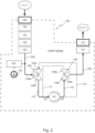
- FIG. 2 shows the pump system 100 operational in a first mode.
- air is being pumped through the pump system from the primary port 106 to the secondary port 107.
- the primary port 106 can be connected to an accessory, such as a bag or a jar or a food storage box, etc. Then, air can be sucked out of the accessory to create an negative pressure.
- the secondary port 107 is in fluid connection with the environment outside of the pump system, in particular outside of the housing. To allow the air to pass through the pump system 100 from the primary port 106 to the secondary port 107, the first arm 104a and the second arm 104b of the first three-way valve 104 are open and the third arm 104c of the first three-way valve 104 is closed.
- the first arm 105a and the third arm 105c are open, while the second arm 105b is closed.
- the air can be sucked into the pump system 100 via the primary port 106, the first three-way valve 104, the pump 101, the second three way-valve 105 to the secondary port 107.
- the primary port 106 thus may serve as an inlet to the pump system 100
- the secondary port 107 may serve as an outlet to the pump system 100 in the first operational mode.
- the primary port 106 is coupled to an accessory such as a bag or a food container, air can be sucked out of the accessory, e.g. the bag or the container, and a negative pressure, a so-called vacuum, can be created in the accessory.
- the first arm 104a and the third arm 104c of the first three-way valve 104 is open, while the second arm 104b is closed.
- the first arm 105a and the second arm 105b is open, while the third arm 105c is closed.
- air can be pumped through the pump system 100 from the secondary port 107 to the primary port 106.
- the secondary port 107 then serves as an inlet to the pump system 100, and the primary port 106 then serves as an outlet to the pump system 100.
- air can be sucked into the pump system 100 via the secondary port 107 to the second three-way valve 105 via the pump 101 to the first three-way valve to be blown out via the primary port 106.
- the primary port 106 is coupled to an accessory, air can be blown into the accessory, e.g. for aerating or making foam etc.
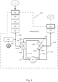
- Figure 4 shows a scheme of the third operational mode, which is an alternating mode in which the pump system 100 switches between the first 'sucking' mode and the second 'blowing' mode.
- the three-way valves 104 and 105, and in particular the respective second arms 104b, 105b and the third arms 104c, 105c thus switch between an open condition and a closed condition. Switching between the first mode and the second mode typically is done rather frequently, at predetermined time intervals, e.g. every 1 second, or every 0,10 second or any other suitable time interval that provides for reaching a specified level of negative pressure.
- the pump system 100 further may comprise additional components, as schematically indicated in the schemes of figures 2 , 3 , 4 .
- particle filters 120, 121 in the primary port channel 108 and the secondary port channel 109 respectively.
- the particle filter 120, 121 may prevent particles, such as dust, sand or other dirt from entering into the pump system 100 and damaging the valves 104, 105 and/or the pump 101.
- a pressure relief valve 122 can be provided, e.g. in the primary port channel 108 to prevent an overpressure in the pump system 100.
- various moisture protective measures can be provided in the pump system 100 to detect whether moisture is present in the air that is passing through the pump system 100 and/or to prevent moisture from passing through the valves and/or the pump, since moisture can potentially harm a pressure sensor 130, the valves 104, 105 and/or the pump 101 as well. Moisture may potentially be damaging to any electronic components that may be present in the apparatus comprising the pump system 100.
- a protective film 123 can be provided upstream of the pump 101, preferably in the primary port channel 108. Such a protective film 123 can be arranged to allow air to pass through, but preventing fluid or moisture droplets to pass through.
- this fluid is then prevented from further entering the pump system 100 via the protective film 123. It may also be considered to provide a protective film in the secondary port channel 109 to prevent moisture sucked in with the air via the secondary port 107, e.g. in the second operational mode, to reach the valves 105, 104 and/or the pump 101.
- the protective film can be blown clean when the pump is in the second operational mode, thus blowing the moisture away from the film towards the primary port 106 that serves as outlet in the second operational mode of the pump system 100.
- An other moisture detection element may be a fluid sensor 124 provided upstream of the pump 101, for example in the primary port channel 108 and/or in the secondary port channel 109.
- a fluid sensor 124 may for example be embodied as two electrical contact points at a distance from each other in the channel. As soon as moisture is flowing through the channel, the two contact points are being brought in electrical contact, so an electrical voltage drop can be detected, indicating that moisture is detected in the channel.
- a moisture absorbing material may be placed upstream of the pump 101, for example in the primary port channel 108 and/or in the secondary port channel 109.
- the moisture absorbing material may be positioned translatable in a bypass chamber in the pump system 108, allowing air to pass along the material via the bypasses when the pump system 100 is operating in the first mode, and forcing air to pass through the material when the pump system is in the second mode.
- the material can be translated towards a shoulder of the chamber in which it is placed thus closing the bypasses and forcing the air to pass through the material.
- any moisture captured or absorbed in the material can be blown out of the material when the pump is operating in the second mode, thus providing for self-cleaning of the moisture absorbing material.
- Another protective measure for moisture may be to provide a fluid internal reservoir 125 upstream of the pump 101, preferably in the primary port channel 108.
- any moisture or liquid that passes through the primary port channel 108 is then collected in the fluid internal reservoir.
- the fluid internal reservoir When the fluid internal reservoir is filled, it may be emptied by a user.
- Such a fluid internal reservoir 125 may prevent that liquid that is, accidently or not, sucked via the primary port 106 reaches the valves 104, 105 and/or the pump 101. It is noted that various measures for moisture detection can be combined, as well as can be positioned elsewhere in the pump system, e.g. in the secondary port channel etc.
- the pressure sensor 130 is provided to the primary port channel 108, so the actual pressure in the primary port channel 108 can be measured. For example, when the pump system 100 is operating in the first mode, it can be measured whether the required negative pressure is already achieved. Or, when the pump system 100 is operating in the second blowing mode, it can be measured whether an positive pressure is obtained. By providing such a pressure sensor 130, the functioning of the pump 101 and/or of the pump system 100 can be monitored.
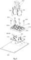
- valves 104, 105 are embodied as three-way solenoid valves 104, 105 that are indirectly connectable to a printed circuit board 200.
- the solenoid valves 104, 105 are mounted, via conventional mounting elements such as screws 201, to a support 202.
- the support 202 is configured to receive the solenoid valves 104, 105 with seats 203 for connecting the solenoid valves 104, 105.
- Tubular pillars 212 are provided around which hoses can be received.
- the fluid connections are advantageously established by hoses, such as hoses 207.
- hoses 207 can be connected to the support 202.
- the support 202 is provided at one side 202a with the hose receiving elements 212, embodied as tubular pillars.
- the support 202 is provided with recesses 204.
- the recesses 204 provide for a fluid connection between the valves 104, 105 and the pump 101.
- the support 202 in particular, the side 202b of the support 202 serves as a manifold fluidly connecting the valves and the pump of the pump system.
- the recesses 204 are closed by the printed circuit board 200 to form one of the channels 110, 111, 112, 113.
- a sealing element 205 is provided to sealingly close the recesses 204.
- the support 202 is connected to the printed circuit board 200 with conventional fastening elements, such as screws 206, passing through the sealing element 205.
- the channels fluidly connecting the valves 104, 105 to either the primary port 106 or the secondary port 107 or the pump 101 are embodied as hoses 207.
- a recess 208 is provided in which a membrane 209 can be placed, thus providing for the pressure sensor 130.
- there is an opening 210 in the sealing element 205 as not to tamper the functioning of the pressure sensor.
- an area 211 is dedicated to receive the support 202 with the valves 104, 105.
- Figure 6 shows a locking guide 213 that can be used to guide and tighten a number of hoses 207 forming the fluid connections of the pump system towards their associated hose receiving elements 212 on one side 202a of the support 202.
- the locking guide 213 itself is also provided with a number of pillars 214 through which a hose 207 can be guided.
- a single hose 207 is guided through two guide pillars 214 such that both ends of the hose 207 are at one side of the locking guide 213, preferably the side facing the support 202.
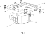
- FIG 8 shows an exploded view of an embodiment of an apparatus 1 according to the invention.
- the apparatus 1 comprises a pump system 100 as shown in the figures 1 - 7 that is arranged in a housing 2.
- the housing 2 here comprises multiple parts, a bottom part 2a, a wall part 2b and a top part 2c.
- the bottom part 2a forms the base, while the top part 2c comprises a user contact area 4a of the user interface 4.
- the printed circuit board 200 not visible, with the sealing member 201 and the support 202 of the valves 104, 105 is mounted upside down in the housing with the valves facing downwardly.
- the other side of the printed circuit board can be used to connect the electronic components 4b of the user interface 4 to.
- a relatively compact and concise apparatus 1 can be obtained, in which the space available in the housing 2 is used as efficiently as possible.
- the pump 101 is mounted resiliently to the housing 2.
- the pump 101 is connected to a pump frame 5 using a spring connection 6.
- the spring connection 6 can be embodied as a plate spring encompassing the pump 101.
- the pump frame 5 is resiliently mounted to the housing 2, in particular to the bottom part 2a.
- the fastening elements 7, here conventional screws, that connect the pump frame 5 with the bottom part 2a are received in resilient busses 8.
- the resilient busses 8 are provided with protrusions 9, e.g. ribs or flanges, that can rest onto a shoulder 16 of the pump frame 5. As such, vibrations of the pump 101 may not or only limitedly be transmitted to the housing 2, in particular to the bottom part 2a.
- a hose 10 that can be used to couple to an accessory can be rolled up around the bottom part 2a of the housing 2, and can thus be stored inside of or around the housing 2 when not in use.
- the hose 10 is flexible and can be rolled out when in use, or rolled up for storage.
- the primary port 106 and the secondary port 107 of the pump system 100 can be provided in the housing 2, and may thus form a connection with the environment outside of the housing. Further, the primary port 106 is also arranged to provide for a coupling with an accessory, such as a bag or a food container or a tray or a bowl or a jar etc. while the secondary port 107 is arranged for fluid connection with the outside environment to blow out air to the outside or the suck in air from the outside environment, outside of the housing 2.
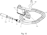
- Figure 10 shows an embodiment in which some of the measures for moisture detection are shown, such as the internal reservoir 125, the fluid sensor 124. Further, the hose forming the primary port channel 108 is also partly shown.
- the primary port 106 is here engageable to the hose 10, wherein the end 11 of the hose 10 is provided with a coupling element 12 for coupling with an accessory.
- the coupling element 12 can for example simply be placed on an opening in an accessory, or may be placed in a corresponding recess of an accessory etc. Many variants are possible.
- a filter 120 can be provided as well.
- a ring 13, fastening element 14 and bus 15 are provided that connect the coupling element 12 with the end 11 of the hose 10.
- Removing of the coupling element 12 from the end 11 of the hose 10 may give access to the filter 120, if present, and/or to a moisture absorbing material, if present. As such, a filter and/or a moisture absorbing material can be replaced if required.
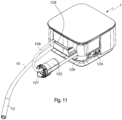
- Figure 11 shows an alternative embodiment of an internal fluid reservoir 125.
- the internal fluid reservoir 125 is at one side coupled to the hose 10 having the coupling element 12 for coupling to an accessory at its end.
- the fluid reservoir 125 is at another side coupled to a hose 108.
- the fluid reservoir 125 is during use stored internally inside of the housing 2.
- the fluid reservoir 125 is used in combination with a moisture detection element 124.
- the functioning of the moisture detection element 124 is explained in relation to figure 12 .
- the size of the fluid reservoir 125 is constrained by the available space in the housing, but is preferably as large as twice the volume that can be pumped in a time interval between detection of the moisture and, preferably automatic, stopping of the pump motor.
- the moisture detection element 124 when it detects moisture, it sends a detection signal to the control unit that then instructs the pump to stop functioning.
- the user can remove the internal reservoir 125 from the housing and can empty the reservoir 125.
- the reservoir 125 can be inserted into a chamber 126 in the housing.
- the chamber 126 is accessible from the outside by the user, such that the user can remove the reservoir 125 from the chamber 126.
- the flexible hose 108 and the hose 10 are arranged to move along with the reservoir 125.
- the reservoir 125 is provided with a lid 127 that can be removed from the reservoir 125. After removal of the lid 127, the reservoir 125 can be emptied and cleaned when necessary.
- the moisture detection element 124 is here provided as a plate like element 130 with two electrical contact areas 131.
- the plate like element 130 is further provided with electric wiring, not shown, providing for the electrical connection with the printed circuit board, and, preferably the control unit.
- the control unit recognizes that moisture is detected and the control unit can then send a signal to the pump to stop operating.
- the plate like element 130 can be inserted through a slit in the reservoir 125 and through a slit in the housing wall 2.
- the plate like element 130 has a U-shaped end. On each leg of the U-shape an electrical contact area 131 is provided. The electrical contact areas 131 are in contact with a moisture sensor in the reservoir 125. At the same time, the U-shape provides for a form-locking of the reservoir 125 to the housing 2 thus preventing accidental removing of the reservoir 125 from the housing 2. It is after removal of the plate like element 130, that the form locking is undone and the reservoir 125 can be taken out of the housing 2 for emptying.
- the container 125 unlocks a retaining mechanism for retaining the plate like element 130 in place, so that the plate like element 130 preferably can only be inserted back into the housing 2 when the reservoir 125 is also in the housing 2.
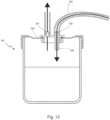
- Figures 13 , 14a , 14b , 14c and 15 give an example of a fluid external container 300 that is to be positioned outside of the apparatus, and to be fluidly connected to the primary port 106 of the apparatus.
- the fluid external container 300 can be used as a moisture detection element or as a moisture receptacle.
- the fluid external container 300 comprises a first opening 301 that is fluidly connectable to the primary port 106 and a second opening 302 that is fluidly connectable with a further element, such as an accessory.
- the external container 300 is closed air-tightly with a cover 305.
- the apparatus can also be used for sucking up liquid, e.g.
- the second opening 302 can be connected to a hose 304, the end of which can be used to drain liquid.
- the pump system of the apparatus thereto needs to be operated in the first 'sucking' mode, such that air can be pumped through the system from the primary port 106 towards the secondary port 107.
- a sufficient negative pressure can be created, such that air and/or liquid can be sucked up with the end of the hose 304.
- the liquid, or moisture contained in the air falls down in the receptacle 300 and is then received in the receptacle 300.
- the second opening 302 is provided as a tube 306 that extends lower into the receptacle 300 than the first opening 301.
- Such liquid receiving external container 300 can be used instead of or in addition to the measures for moisture detection provided in the apparatus, as explained above.
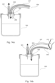
- a third opening 303 is provided that can be opened or closed.
- the third opening 303 is here provided with a hose 307, the end of the hose 307 can be opened or closed by a finger, as shown in fig. 14b .
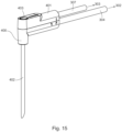
- a liquid injector 400 shown in figure 15 can be coupled to the second opening 302 and the third opening 303.
- the external container 300 can also be used to dispense liquid out of the external container 300.
- the first opening 301 is fluidly connected with the primary port 106 of the apparatus 1. With the pump system in the first mode, air is being sucked from the primary port 106 through the system towards the secondary port 107. Since the first opening 301 is connected to the primary port 106, air is being sucked through the first opening 301 as well.
- the second and the third opening may both serve as entry openings to the external container 300 via which air and/or liquid can be sucked up simultaneously.
- the first opening 301 is fluidly connected to the primary port, air flows from the primary port via the first opening 301 into the external container 300.
- the third opening 303 is closed, e.g. by a finger at the end of the hose 307 that is connected to the third opening 303, a positive pressure is created in the external container 300.
- the tube 306 of the second opening 302 is sufficiently long, preferably it extends until just above a bottom of the external container 300, then liquid contained in the external container 300 can be pushed out of the external container 300 through the tube 306 and the hose 304. This mode can for example be used to hydrate food during cooking.
- the liquid injector 400 shown in figure 15 can be coupled to second opening 302 and the third opening 303 respectively via hoses 304 and 307.
- the hoses 304 and 307 end in an injector head 401 from which a hollow injector needle 402 extends.
- the third opening 303 can be closed by a finger, here an opening 403 in the injector head is provided that is in fluid connection with the third opening 303.
- the liquid injector 400 With the liquid injector 400 connected to the cover 305 of the external container 300 and the external container 300 connected to the primary port of the apparatus, the liquid injector 400 can be used for injection liquid contained in the receptacle 300 directly into food when the pump is operating in the second mode.
- the injector needle 402 can penetrate the food such that the liquid can be injected inside of the food. This can be advantageous for applying marinade to meat or to inject a sauce into pastry for example. Many uses are possible.
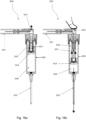
- FIGS 16a, 16b give an example of an accessory being here a fluid injector 500 for connection to the apparatus 1.
- the fluid injector 500 comprises a first opening 501 that is fluidly connectable to the primary opening 106.
- the first opening 501 fluidly connects to a third opening 503 and to a piston chamber 508.
- the piston chamber 508 comprises a piston 504 which divides the piston chamber 508 into a first chamber 505 and a second chamber 506.
- the first chamber 505 is fluidly connected to the first opening 501 and the third opening 503.
- the second chamber 506 is fluidly connected to the second opening 502 of the accessory, here the injector needle 502.
- the first chamber 505 comprises a resilient element 507, such as a spring 507, biased to pull the piston 504 towards a first position in which a piston chamber entrance fluidly is connected to the first opening 501 and the third opening 503.
- the first position is an upper position of the piston 504 in the piston chamber 508.
- the second position of the piston 504 is a more downward position.
- the user may then insert the injector needle 502 e.g. into food or liquid for example to insert fluid received in the second chamber 506 thereto.
- the fluid received in the second chamber 506 may be distributed over food, e.g. to marinate.
- the piston 504 is pushed towards the second position, upon releasing the air pressure, e.g.
- the user can again close off the second opening 502 with e.g. a finger or another element.
- the air pressure in the first chamber 505 will increase again, causing the piston 504 to move towards the injector needle 508, thereby pushing the fluid contained in the second chamber 506 out through the injector needle 502.
- the second chamber 506 of the fluid injector 500 can be seen as the equivalent of the external container 300 disclosed in Figures 13 , 14a , 14b and 14c .
- the external container is in fact integrated to the injector 500.
- the fluid injector 500 can be seen as a combination of the external container 300 of figures 14 and the injector needle 400 of Figure 15 .
- the fluid injector 500 can for example be biased to push the piston 504 towards the injector needle 502, to the second position of the piston 504.
- the pump can operate in the first mode to provide a negative pressure in the first chamber 505 in order to counter the spring 507.
- the fluid injector 500 according to this embodiment further may operate in a comparable manner as the fluid injector 500, with the difference that closing off the third opening 503 results in the piston 504 moving away from the injector needle 502 instead of towards it.
- the accessory 500 connected to the apparatus 1 may provide for a system according to an aspect of the invention.
- the accessory 400 and/or the container 300 connected to the apparatus 1 may provide for a system according to an aspect of the invention.
- a kitchen appliance apparatus for using air in the kitchen, comprising a housing, wherein in the housing a pump system is provided which pump system comprises, a primary port, a secondary port, a single direction air pump having an inlet and an outlet; wherein the pump system is operational in a first pump mode in which air can be sucked in via the primary port; the pump system is operational in a second pump mode in which air can be blown out via the primary port; and is operational in a third pump mode in which the pump system is alternatingly sucking in and blowing air via the primary port.
- any reference signs placed between parentheses shall not be construed as limiting the claim.
- the word 'comprising' does not exclude the presence of other features or steps than those listed in a claim.
- the words 'a' and 'an' shall not be construed as limited to 'only one', but instead are used to mean 'at least one', and do not exclude a plurality.
- the mere fact that certain measures are recited in mutually different claims does not indicate that a combination of these measures cannot be used to an advantage. Many variants will be apparent to the person skilled in the art. All variants are understood to be comprised within the scope of the invention defined in the following claims.
Description
- The invention relates to an apparatus for using air in the kitchen.
- An apparatus for using air in the kitchen, either a consumer kitchen or a professional kitchen, is known. There is e.g. known an apparatus to automatically aerate wine in a carafe or glass. Also, there is known an apparatus having a chamber for conserving food and an integrated vacuum pump. The vacuum pump vacuums the chamber such that the food contained in the chamber can be longer conserved. The use of air in the kitchen can be helpful for vacuuming a bowl or a tray or a jar or a bag in which food can be stored and/or marinated. Also, air can be used for aerating wine or for making foam of hot milk.
-
US6832634B1 discloses a system for carbonating a liquid with carbon dioxide gas comprising a pressurized source of carbon dioxide gas, a user-operable three-way valve system having a first, a second, and a third orifice providing a first, a second and a third valve state, which in the first state connects the first orifice with the second orifice, in the second state connects the second orifice with the third orifice, and in the third state closes internal passage between all orifices, the valve system connected from the first orifice and a conduit to the pressurized source of carbon dioxide gas, and a closure assembly having an interface to a nozzle of a container for liquid and an orifice connected through a conduit to the second orifice of the three way valve system. - A drawback of all these apparatuses is that they are dedicated for a single function, also they appear to be rather bulky requiring a lot of space in the kitchen. There is a need for a more versatile and compact apparatus for using air in the kitchen.
- Thereto, the invention provides for an apparatus according to
claim 1. - In a first pump mode, the pump operates in suction mode. In a second pump mode, the pump operates in blowing mode, and in the third pump mode, the pump operates in alternating mode.
- The apparatus can thus be used in the first mode, that can be used for vacuuming, for example, a coupled accessory, such as a jar or a bag or a pot or a tray or any other container for storing food. The apparatus can also be used in a second mode, that can be used for example, for making foam or aerating etc. Further, advantageously, the apparatus can also be used in a third mode in which it can alternatingly suck air out of, for example, a coupled accessory, and blow air into the coupled accessory, e.g. for marinating food enclosed in the accessory. As such, a compact and versatile apparatus can be obtained that allows the easy use of air in the kitchen for various applications. Contrary to the prior art systems, there is now a single stand-alone apparatus that can provide multiple functions with air in the kitchen. By providing a single direction air pump that is fluidly connected with two three-way valves, the pump system in the apparatus can be operated in two directions without the use of an expensive and complex dual-way pump. Thus, a relatively cost effective pump system with a limited number of components is obtained, such that the system can be compact. A compact system can be advantageous as it consumes relatively little space in the kitchen where the kitchen top becomes more crowded with various apparatuses. Also, the compact apparatus is relatively easy to handle.
- Advantageously, the apparatus further comprises a control unit that is configured for controlling the operation of the three-way valves depending on the pump mode. By providing the control unit, switching between the different pump modes is possible without a complex mechanical switching system. The control unit may be provided on a printed circuit board arranged inside of the housing of the apparatus, forming part of the pump system.
- By providing the pump system with a pressure sensor arranged in a channel connecting the primary port with the first three-way valve, the pressure in the pump system can be monitored. In particular, when the pump system is in the first mode, it can be monitored whether a negative pressure is being built up in an accessory coupled to the primary port and out of which air is being pumped. When a sufficient negative pressure is achieved in the coupled accessory, measured by the pressure sensor in e.g. the primary port channel, the pumping process may be stopped, for example automatically by a control unit. Alternatively, the pressure sensor can monitor the positive pressure built up by the pump in the second mode for blowing air out of the primary port. Also, in the third mode, the pressure sensor can be used to monitor the difference between negative and positive pressure. A negative pressure or an negative pressure or sometimes called vacuum, is considered to be a pressure below the atmospheric pressure. A positive pressure is considered to be a pressure above the atmospheric pressure.
- By arranging a protective film in the primary port channel that connects the primary port with the first three-way valve, wherein the protective film is arranged to allow air pass through and liquid not, at least the three-way valve can be protected from moisture ingress. In the event of moisture ingress via the primary port, the moisture, and/or any other dirt, is being accumulated by the film. As such, when bringing the pump system in the second pump mode, the accumulated moisture and/or dirt can be blown out of the primary port channel and be removed from the primary port channel via the primary port. Thus, self-cleaning of the pump system is possible. Of course, additionally and/or alternatively other moisture protection can be possible, as will be elaborated later. Preferably, the protective film is arranged between the primary port and the pressure sensor, as to protect the pressure sensor from moisture and/or dirt ingress as well.
- Advantageously, the primary port is arranged for connection to an accessory. The accessory can for example be a food container that is coupled to the primary port, or can be a hose engaged to the primary port, the hose itself may then be arranged at a free end thereof for connection to the accessory. The primary port is preferably arranged in the housing, more preferably in a wall of the housing, as to form an interface between the pump system inside of the housing, and the outside of the housing. The primary port may for example be an opening in the housing through which the hose can be engaged, wherein the hose at one end is arranged for, direct or indirect, connection to the first three way-valve and at its other free end is provided with a coupling element for coupling with an accessory. Alternatively, the primary port can be a coupling element to which an accessory can be directly coupled. Alternatively, the primary port provides for the interface with the pump system and an accessory or a coupling element outside of the pump system. The primary port may then be configured inside of the housing and the connection may be provided by a hose that at one end is connected with the pump system and at another end is provided with a coupling element for connection to an accessory.
- Also, the secondary port is preferably arranged in the housing, more preferably in a wall of the housing, to form an interface with the pump system inside of the housing and the environment outside of the housing. The secondary port is in particular arranged to form a fluid connection with the environment outside of the housing, such that air can be blown out via the secondary port when the pump system is in the first mode and air can be sucked in via the secondary port when the pump system is in the second mode, as well as in the alternating mode.
- By providing the three-way valves as three-way solenoid valves, relatively compact and easy to control valves are used. Advantageously, the pump system further comprises a printed circuit board to which the three-way valves are connectable. The three-way valves, in particular the three-way solenoid valves, may be directly connectable to the printed circuit board, or may be indirectly connectable to the printed circuit board. In an embodiment, the three-way solenoid valves are indirectly connectable to the printed circuit board, wherein the solenoid valves are mounted on a support and the support is mountable on the printed circuit board. As such, an indirect connection with the printed circuit board can be established allowing a compact arrangement of the valves inside of the housing of the apparatus. Also, by connecting the solenoid valves via a support to the printed circuit board, the system may be relatively easy to assemble.
- Advantageously, the valves are mounted to one side of the support and the other side of the support is provided with recesses for forming a channel connection with one of the valves or the pump. When the support then is mounted to the printed circuit board, the recesses are closed by the printed circuit board to form a channel through which the air that is being pumped can flow. Part of the channels of the pump system can thus be partially integrated in the support and upon installation a channel can be formed in which the recesses are closed by the printed circuit board. As such, the support is also used to form a fluid connection between the valves and/or the pump providing for a relatively compact build-up of the pump system. As such, the support is arranged as a manifold for multiple fluid connections.
- Advantageously, a sealing member is provided between the support and the printed circuit board to seal off the channels thus formed. One of the recesses in the support may be provided with an arrangement for a pressure sensor, e.g. with a seat in which a pressure membrane can be held. The pressure sensor may thus be arranged in the thus formed channel. In that case, the sealing member leaves the pressure sensor free.
- The fluid connections between the valves and/or the pump and/or the primary or secondary port are advantageously provided as flexible hoses arranged inside of the housing. The flexible hoses provide for an easy to assemble and relatively cost-effective fluid connection in the pump system, and can be relatively easy folded inside of the housing. Advantageously, a locking guide is provided through which at least one of the hoses is guided, in particular the hoses downstream of the pump. By providing such a locking guide, assembly of the hoses inside of the housing and connection of the hoses to the support becomes easier. The locking guide can be provided with at least two openings through which a hose can be inserted such that the hose at one end is inserted through such an opening and at another end as well. Both ends of the hose may then extend at one side of the locking guide. The locking guide advantageously is arranged at the side of the support opposite the recesses-side. As such, by mounting the locking guide onto the support and by tightening the locking guide to the support, the hoses are automatically connected to the associated openings in the support, and thus, a tight fit can be obtained. Advantageously, the locking guide is in particular suitable for hoses that are subject to a positive pressure. Hoses that are subject to a negative pressure may form a tight fit due to the negative pressure during use.
- In an embodiment, the control unit is provided on the same printed circuit board as the three-way valves are connectable to. As such, an even more compact arrangement can be provided, and the pump system can be operational using a single printed circuit board.
- Additionally, the apparatus may be provided with a user interface, that is in operational communication with the control unit. Advantageously, the user interface is directly provided on the printed circuit board, in particular the electronic components of the user interface are directly provided on the printed circuit board, while the components that are configured to be in contact with the user are preferably provided on a wall of the housing. For example, the user interface can comprise touch buttons that are configured for contact with the user, namely the user contacts or presses the area on the wall of the housing that is dedicated to that end. Below such a contact area, typically the buttons are provided that, preferably, may or, alternatively, may not be directly provided on the printed circuit board. Alternatively, the user interface can be a touch screen, display, panel etc. Also, the user interface may be provided on a mobile communications device, in particular onto a smart mobile communications device, such as a smart phone, tablet or computer that is in wireless communication with the control unit. For example, the user contact area of the user interface may be provided at top side of the housing with the printed circuit board positioned immediately beneath it, such that the contact area can be in direct contact with the buttons provided on the printed circuit board.
- By supporting the pump resiliently in the housing, vibrations and/or noise initiated by the pump may be obviated or at least limited from being transmitted to the housing. As such, it may be obviated that the apparatus might start moving during operation of the pump, e.g. on a table top or a kitchen top and/or it may be obviated that the housing is vibrating itself. Also, by limiting the transmission of any vibrations from the pump to the housing, the lifetime of the housing may be increased. Advantageously, the pump is also supported independently of other components of the pump system, such as the printed circuit board and/or the valves. By supporting the pump independently and/or resiliently with respect to the other components, the other components, such as the relatively sensitive electronic components can be protected from vibrations, which may increase their lifetime. For example, to that end, the housing may comprise a base part and an upper part, wherein the pump is resiliently supported to the base part. As such, the upper part of the housing can be independent from the base part, and can remain free of vibrations from the pump.
- Advantageously, the pump system is provided with a moisture detection element in a channel upstream of the pump. Moisture in the pump system may adversely affect the functioning of the pump, so an early detection may be advantageous for the functioning of the pump system. Upon detection of moisture in the pump system, the working of the pump may be stopped to allow the moisture to be removed from the pump system, or, a moisture removal element may be in place to prevent moisture from harming the pump. For example, the moisture detection element may comprise an electrical moisture sensor e.g. comprising two electrical contact points that are arranged in a channel upstream of the pump, preferably in a channel between the primary port and the first three-way valve. When there is moisture in the air passing by the electrical contact points of the electrical moisture sensor, the electrical contact points are brought in electrical contact resulting in a voltage drop. Such a voltage drop can be detected and be signaled that moisture is detected. Such a detection signal may then e.g. be transmitted to the control unit that may shut down the pump or may bring the pump into the second mode to blow the moisture out of the channel.
- Alternatively and/or additionally, the moisture detection element may comprise a moisture absorbing material arranged in a channel upstream of the pump, preferably in a channel between the primary port and the first three-way valve. The moisture absorbing material may e.g. be a foam in which the moisture can be captured, once the foam is saturated a detection signal may be sent to the control unit to shut down the pump until the moisture absorbing material is replaced. The moisture absorbing material for example can be a material that swells when it comes in contact with moisture and thus may block the channel, thereby the working of the pump may be stopped.
- Alternatively and/or additionally, the moisture detection element may comprise and optical sensor detecting fluid droplets in a channel upstream of the pump. The optical sensor may see fluid passing by in the channel upstream of the pump, and may signal detection of any fluid.
- Alternatively and/or additionally, the moisture detection element may comprise an internal reservoir that is fluidly connectable to a channel upstream of the pump, preferably connectable to a channel between the primary port and the first three-way valve. The internal reservoir may thus capture any moisture of fluid entering the pump system via the primary port, e.g. until the internal reservoir is filled. Advantageously, the internal reservoir holds any liquid entering the internal reservoir between moisture detection and halting of the pump. Advantageously, additional to the internal reservoir a moisture detection sensor may be present, e.g. in the channel upstream of the internal reservoir and/or in the internal reservoir itself. Then, a detection signal may be sent such that the internal reservoir can be emptied. The internal reservoir preferably is provided in the housing and accessible for the user, such that the user can access it to remove it from the housing and empty it. As such, the internal reservoir may form part of the pump system and of a moisture detection element for obviating moisture to adversely effect the functioning of the pump. The size of the internal reservoir may thus be constrained by the available space inside of the housing, but is preferably at least as large as twice the volume displacement of air and/or liquid in the time between detection and the halting of the first pump mode. Advantageously, the functioning of the pump in the first pump mode is stopped upon detection of moisture by the moisture detection sensor and/or the internal reservoir. Then, the pump may continue working in the second pump mode in an attempt to blow the channel clean of moisture. The pump may continue working in the second pump mode until the user actively stops the working of pump. The pump may then only restart when the internal reservoir has been emptied. The user may then restart the pump, and/or it can be checked by the moisture detection element that no moisture is detected and thus, effectively, the internal reservoir was emptied before restarting the pump.
- Alternatively and/or additionally, the moisture detection element may comprise an external container that is fluidly connectable with the primary port. The external container is positioned outside of the housing and is separate from the housing. The external container advantageously has a first opening for connection with the primary port and has a second opening for connection with an accessory. As such, the external container is positioned between the accessory and the primary port to capture any moisture that is being sucked in from the accessory. Advantageously, the external container is provided with a third opening that is in fluid connection with the environment outside and can be closed so a negative pressure can be created in the external container, and the accessory coupled to it, when the pump is in the first mode, or an positive pressure can be created in the external container, and the accessory coupled to it, when the pump is in the second mode. When the third opening is open, the external container is in fluid connection with the environment outside of the external container.
- Alternatively and/or additionally, an accessory may be provided wherein the accessory comprises an external container. The accessory advantageously has a first opening for connection with the primary port. The accessory advantageously has a second opening fluidly connecting the first opening to the environment. The accessory advantageously has a third opening fluidly connecting the external container to the environment, which may be opened or closed to provide a fluid connection with the environment or with the second opening respectively. The accessory may be embodied as a fluid injector wherein the external container is integrated to the injector. So, instead of providing a separate external container for receiving fluid, the container is integrated to the injector. By providing an accessory comprising an integrated fluid receiving container, a compact design may be achieved.
- Alternatively and/or additionally, a pressure created by the pump may be transferred to an external container by a pressure transferring element. The pressure transferring element can for example be a piston. By transferring the pressure created by the pump by the pressure transferring element, no fluid connection between the pump and the external container is required. As such, fluid transmission between the pump and the external container may be obviated and contamination may be avoided. Advantageously, the accessory as an injector with integrated container, may comprise a piston that is biased towards a first position. When the injector is connected to the primary port of the apparatus, the apparatus may provide sufficient pressure to overcome the biasing force of the piston to move the piston to a second position towards the second opening of the accessory, typically the outlet or injection needle. Typically, in the first position of the piston, the volume of the receiving container is larger than the volume of the receiving container in the second position. In the first position of the piston, the piston is biased towards the first opening of the injector accessory. As such, fluid or liquid can be sucked up with the injector into the container, but can also be pumped out of the container of the injector. As such, liquid can be sucked up from, e.g. a receptacle, into the integrated container of the injector, and/or liquid received in the integrated container of the injector can be ejected out of the injector into food or can be sprayed out of the injector over food.
- In another aspect there is provided a system comprising an apparatus and an accessory that is fluidly connectable with the primary port. Advantageously, the accessory is connectable to the primary port via an external container having a first opening fluidly connectable to the primary port of the apparatus, and having a second opening that is fluidly connectable to the accessory, which may be a hose. Liquid or moisture accidentally, or deliberately, present in the air flow blown out or sucked in via the second opening, can be received in the external container. By providing such an external container, it may be avoided or limited that liquid enters into the pump system.
- Further, the external container may be provided with a third opening for connection with the environment outside the external container, wherein opening or closing of the third opening provides for creating a negative pressure or a positive pressure in the external container depending on the operational mode of the pump system. As such, via the accessory liquid from the external container can be removed from the container via the second opening of the container and the accessory. Or, liquid can be sucked up via the accessory, which may be a simple hose, to be received in the container. For example, the accessory connectable to the external container can be provided as a fluid injector. The fluid injector may facilitate injection of liquid into food, such as meat, or may facilitate distribution of liquid over food. Also, the fluid injector may allow more easy sucking up of liquid.
- Alternatively, the accessory may be provided as a fluid injector to which the container for receiving liquid is integrated. The fluid injector may comprise a piston chamber receiving a piston therein, such that the piston divides the chamber in a first chamber in fluid connection with the first opening of the accessory, and a second chamber in fluid connection with a second opening, namely the outlet or injection needle, of the accessory. The second chamber is then embodied as the container for receiving liquid therein.
- Further advantageous embodiments are represented in the subclaims.
- The present invention will be further elucidated with reference to a drawing comprising figures of exemplary embodiments. In the drawing shows:
-
Figure 1 a schematic presentation of a pump system for an apparatus according to the invention; -
Figure 2 a schematic presentation of the pump system offigure 1 in the first mode; -
Figure 3 a schematic presentation of the pump system offigure 1 in the second mode; -
Figure 4 a schematic presentation of the pump system offigure 1 in the third mode; -
Figure 5 a schematic exploded view of an embodiment of a pump system for an apparatus according to the invention; -
Figure 6 a schematic exploded view of an embodiment of a support with a locking guide; -
Figure 7 a view of the side of the support containing the recesses for forming the channels; -
Figure 8 a schematic exploded view of an embodiment of an apparatus according to the invention; -
Figure 9 a schematic exploded view of an embodiment of a resilient support of the pump of the pump system; -
Figure 10 a schematic view of an embodiment of a moisture detection element with an internal reservoir for use in the pump system; -
Figure 11 a schematic view of another embodiment of an internal reservoir for use in the pump system; -
Figures 12a, 12b, 12c a schematic representation of a moisture detection element in combination with an internal reservoir; -
Figure 13 a schematic view of an embodiment of a moisture external container for connection to the apparatus; -
Figures 14a, 14b ,14c a schematic view of a second embodiment of a moisture external container for connection to the apparatus; -
Figure 15 a schematic view of an embodiment of a fluid injector for use with the external container offigure 14 ; -
Figures 16a, 16b a schematic view of an alternative embodiment of a fluid injector for connection to the apparatus. - It is noted that in the figures corresponding elements are designated with corresponding reference signs. The figures are not to scale.
-
Figure 1 gives a schematic representation of apump system 100 for use in a kitchen appliance apparatus for using air in the kitchen. Thepump system 100 comprises a singledirection air pump 101 having aninlet 102 and anoutlet 103. Thepump system 100 further comprises a first three-way valve 104 and a second three-way valve 105. The first three-way valve 104 is fluidly connected to theinlet 102 of thepump 101. The second three-way valve 105 is fluidly connected to theoutlet 103 of thepump 101. Further, thepump system 100 comprises aprimary port 106 and asecondary port 107. Theprimary port 106 is fluidly connected with the first three-way valve 104 and thesecondary port 107 is fluidly connected with the second three-way valve 105. Between theprimary port 106 and afirst arm 104a of the first three-way valve 104, achannel 108 is provided to establish the fluid connection, referred to as theprimary port channel 108. Between thesecondary port 107 and thefirst arm 105a of the second three-way valve 105, achannel 109 is provided to establish the fluid connection, referred to as theprimary port channel 109. - A
second arm 104b of the first three-way valve 104 is via achannel 110, referred to as thefirst inlet channel 110, fluidly connected to theinlet 102 of thepump 101. Asecond arm 105b of the first three-way valve 105 is via asecond inlet channel 111 fluidly connected to theinlet 102 of thepump 101. Athird arm 104c of the first three-way valve 104 is via achannel 112, referred to as afirst outlet channel 112, fluidly connected to theoutlet 103 of thepump 101. Athird arm 105c of the second three-way valve 105 is via achannel 113, referred to as asecond outlet channel 113, fluidly connected to theoutlet 103 of thepump 101. So, the first three-way valve 104 is fluidly connected to theprimary port 106, theinlet 102 of thepump 101, and theoutlet 103 of thepump 101. The second three way-valve 105 is fluidly connected with thesecondary port 107, theinlet 102 of thepump 101 and theoutlet 103 of thepump 101. By providing this configuration, it is possible to have apump system 100 that can operate bi-directionally, while still using a cost-effective singledirection air pump 101, and without using two air pumps or a more complex bi-directional air pump. Depending on the opening and/or closing of one or more arms of the three-way valve, air can be pumped from the primary port to the secondary port or vice versa or even in an alternating mode. Thus, a bi-directionaloperable pump system 100 can be obtained with relatively few components and in a relatively simple set-up, which can keep thepump system 100 relatively cost effective while efficient in operation. Advantageously, thepump system 100 is provided inside of a housing of the kitchen appliance apparatus, wherein theprimary port 106 and thesecondary port 107 can be the connection with the environment outside of the housing. -
Figure 2 shows thepump system 100 operational in a first mode. In the first mode of thepump system 100, air is being pumped through the pump system from theprimary port 106 to thesecondary port 107. Theprimary port 106 can be connected to an accessory, such as a bag or a jar or a food storage box, etc. Then, air can be sucked out of the accessory to create an negative pressure. Thesecondary port 107 is in fluid connection with the environment outside of the pump system, in particular outside of the housing. To allow the air to pass through thepump system 100 from theprimary port 106 to thesecondary port 107, thefirst arm 104a and thesecond arm 104b of the first three-way valve 104 are open and thethird arm 104c of the first three-way valve 104 is closed. In the second three way-valve 105, thefirst arm 105a and thethird arm 105c are open, while thesecond arm 105b is closed. In this first mode, the air can be sucked into thepump system 100 via theprimary port 106, the first three-way valve 104, thepump 101, the second three way-valve 105 to thesecondary port 107. Theprimary port 106 thus may serve as an inlet to thepump system 100, and thesecondary port 107 may serve as an outlet to thepump system 100 in the first operational mode. When theprimary port 106 is coupled to an accessory such as a bag or a food container, air can be sucked out of the accessory, e.g. the bag or the container, and a negative pressure, a so-called vacuum, can be created in the accessory. - In the second operational mode, shown in
figure 3 , thefirst arm 104a and thethird arm 104c of the first three-way valve 104 is open, while thesecond arm 104b is closed. In the second three-way valve, thefirst arm 105a and thesecond arm 105b is open, while thethird arm 105c is closed. As such, air can be pumped through thepump system 100 from thesecondary port 107 to theprimary port 106. Thesecondary port 107 then serves as an inlet to thepump system 100, and theprimary port 106 then serves as an outlet to thepump system 100. In the second mode, air can be sucked into thepump system 100 via thesecondary port 107 to the second three-way valve 105 via thepump 101 to the first three-way valve to be blown out via theprimary port 106. When theprimary port 106 is coupled to an accessory, air can be blown into the accessory, e.g. for aerating or making foam etc. -
Figure 4 shows a scheme of the third operational mode, which is an alternating mode in which thepump system 100 switches between the first 'sucking' mode and the second 'blowing' mode. The three-way valves second arms third arms pump system 100 further may comprise additional components, as schematically indicated in the schemes offigures 2 ,3 ,4 . For example, there is provided forparticle filters primary port channel 108 and thesecondary port channel 109 respectively. Theparticle filter pump system 100 and damaging thevalves pump 101. Further, apressure relief valve 122 can be provided, e.g. in theprimary port channel 108 to prevent an overpressure in thepump system 100. - Also, various moisture protective measures can be provided in the
pump system 100 to detect whether moisture is present in the air that is passing through thepump system 100 and/or to prevent moisture from passing through the valves and/or the pump, since moisture can potentially harm apressure sensor 130, thevalves pump 101 as well. Moisture may potentially be damaging to any electronic components that may be present in the apparatus comprising thepump system 100. As a protective measure, aprotective film 123 can be provided upstream of thepump 101, preferably in theprimary port channel 108. Such aprotective film 123 can be arranged to allow air to pass through, but preventing fluid or moisture droplets to pass through. For example, when accidently sucking in fluid via theprimary port 106, this fluid is then prevented from further entering thepump system 100 via theprotective film 123. It may also be considered to provide a protective film in thesecondary port channel 109 to prevent moisture sucked in with the air via thesecondary port 107, e.g. in the second operational mode, to reach thevalves pump 101. When the liquid or moisture is blocked by theprotective film 123, the protective film can be blown clean when the pump is in the second operational mode, thus blowing the moisture away from the film towards theprimary port 106 that serves as outlet in the second operational mode of thepump system 100. - An other moisture detection element may be a
fluid sensor 124 provided upstream of thepump 101, for example in theprimary port channel 108 and/or in thesecondary port channel 109. Such afluid sensor 124 may for example be embodied as two electrical contact points at a distance from each other in the channel. As soon as moisture is flowing through the channel, the two contact points are being brought in electrical contact, so an electrical voltage drop can be detected, indicating that moisture is detected in the channel. As an other moisture detection element, a moisture absorbing material may be placed upstream of thepump 101, for example in theprimary port channel 108 and/or in thesecondary port channel 109. The moisture absorbing material may be positioned translatable in a bypass chamber in thepump system 108, allowing air to pass along the material via the bypasses when thepump system 100 is operating in the first mode, and forcing air to pass through the material when the pump system is in the second mode. When the pump system is in the second mode, the material can be translated towards a shoulder of the chamber in which it is placed thus closing the bypasses and forcing the air to pass through the material. As such, any moisture captured or absorbed in the material, can be blown out of the material when the pump is operating in the second mode, thus providing for self-cleaning of the moisture absorbing material. Another protective measure for moisture, may be to provide a fluidinternal reservoir 125 upstream of thepump 101, preferably in theprimary port channel 108. Any moisture or liquid that passes through theprimary port channel 108 is then collected in the fluid internal reservoir. When the fluid internal reservoir is filled, it may be emptied by a user. Such a fluidinternal reservoir 125 may prevent that liquid that is, accidently or not, sucked via theprimary port 106 reaches thevalves pump 101. It is noted that various measures for moisture detection can be combined, as well as can be positioned elsewhere in the pump system, e.g. in the secondary port channel etc. - Advantageously, the
pressure sensor 130 is provided to theprimary port channel 108, so the actual pressure in theprimary port channel 108 can be measured. For example, when thepump system 100 is operating in the first mode, it can be measured whether the required negative pressure is already achieved. Or, when thepump system 100 is operating in the second blowing mode, it can be measured whether an positive pressure is obtained. By providing such apressure sensor 130, the functioning of thepump 101 and/or of thepump system 100 can be monitored. - In
figure 5 a possible arrangement of thevalves way valves way solenoid valves circuit board 200. Thesolenoid valves screws 201, to asupport 202. At oneside 202a, thesupport 202 is configured to receive thesolenoid valves seats 203 for connecting thesolenoid valves Tubular pillars 212 are provided around which hoses can be received. In the pump system, the fluid connections are advantageously established by hoses, such ashoses 207. Thesehoses 207, or at least some of them, can be connected to thesupport 202. To that end, thesupport 202 is provided at oneside 202a with thehose receiving elements 212, embodied as tubular pillars. At anotherside 202b of thesupport 202, shown infigure 7 , thesupport 202 is provided withrecesses 204. Therecesses 204 provide for a fluid connection between thevalves pump 101. As such, thesupport 202, in particular, theside 202b of thesupport 202 serves as a manifold fluidly connecting the valves and the pump of the pump system. Therecesses 204 are closed by the printedcircuit board 200 to form one of thechannels circuit board 200 and theside 202b of thesupport 202, a sealingelement 205 is provided to sealingly close therecesses 204. Thesupport 202 is connected to the printedcircuit board 200 with conventional fastening elements, such asscrews 206, passing through the sealingelement 205. The channels fluidly connecting thevalves primary port 106 or thesecondary port 107 or thepump 101 are embodied ashoses 207. Further, in the manifold 202b, arecess 208 is provided in which a membrane 209 can be placed, thus providing for thepressure sensor 130. At the position of pressure sensor, there is anopening 210 in the sealingelement 205 as not to tamper the functioning of the pressure sensor. On the printedcircuit board 200, anarea 211 is dedicated to receive thesupport 202 with thevalves -
Figure 6 shows a lockingguide 213 that can be used to guide and tighten a number ofhoses 207 forming the fluid connections of the pump system towards their associatedhose receiving elements 212 on oneside 202a of thesupport 202. The lockingguide 213 itself is also provided with a number ofpillars 214 through which ahose 207 can be guided. Asingle hose 207 is guided through twoguide pillars 214 such that both ends of thehose 207 are at one side of the lockingguide 213, preferably the side facing thesupport 202. By bringing the lockingguide 213 towards thesupport 202 by tightening thescrews 206, the ends of thehoses 207 guided through thepillars 214 are brought towards their associatedhose receiving elements 212 for a fluid tight coupling. As such, an efficient and compact hose connection and hose arrangement inside of the housing is obtained that can relatively easy be assembled. -
Figure 8 shows an exploded view of an embodiment of anapparatus 1 according to the invention. Theapparatus 1 comprises apump system 100 as shown in thefigures 1 - 7 that is arranged in ahousing 2. Thehousing 2 here comprises multiple parts, abottom part 2a, awall part 2b and atop part 2c. Thebottom part 2a forms the base, while thetop part 2c comprises auser contact area 4a of the user interface 4. The printedcircuit board 200, not visible, with the sealingmember 201 and thesupport 202 of thevalves electronic components 4b of the user interface 4 to. Thus, a relatively compact andconcise apparatus 1 can be obtained, in which the space available in thehousing 2 is used as efficiently as possible. - As can be seen as well in
figure 9 , thepump 101 is mounted resiliently to thehousing 2. In particular, thepump 101 is connected to apump frame 5 using aspring connection 6. Thespring connection 6 can be embodied as a plate spring encompassing thepump 101. Also, thepump frame 5 is resiliently mounted to thehousing 2, in particular to thebottom part 2a. Thereto, the fastening elements 7, here conventional screws, that connect thepump frame 5 with thebottom part 2a are received inresilient busses 8. Theresilient busses 8 are provided with protrusions 9, e.g. ribs or flanges, that can rest onto ashoulder 16 of thepump frame 5. As such, vibrations of thepump 101 may not or only limitedly be transmitted to thehousing 2, in particular to thebottom part 2a. Also the printedcircuit board 200 with thevalves pump 101. Thus, the lifetime of the housing, but also of the electronic components may be increased, as well as that during use, the apparatus can substantially remain in position, instead of starting to move due to the vibrations. This is more convenient for the user. Ahose 10 that can be used to couple to an accessory can be rolled up around thebottom part 2a of thehousing 2, and can thus be stored inside of or around thehousing 2 when not in use. Thehose 10 is flexible and can be rolled out when in use, or rolled up for storage. - The
primary port 106 and thesecondary port 107 of thepump system 100 can be provided in thehousing 2, and may thus form a connection with the environment outside of the housing. Further, theprimary port 106 is also arranged to provide for a coupling with an accessory, such as a bag or a food container or a tray or a bowl or a jar etc. while thesecondary port 107 is arranged for fluid connection with the outside environment to blow out air to the outside or the suck in air from the outside environment, outside of thehousing 2. -
Figure 10 shows an embodiment in which some of the measures for moisture detection are shown, such as theinternal reservoir 125, thefluid sensor 124. Further, the hose forming theprimary port channel 108 is also partly shown. Theprimary port 106 is here engageable to thehose 10, wherein theend 11 of thehose 10 is provided with acoupling element 12 for coupling with an accessory. Thecoupling element 12 can for example simply be placed on an opening in an accessory, or may be placed in a corresponding recess of an accessory etc. Many variants are possible. In thecoupling element 12, or between thecoupling element 12 and thehose 10, afilter 120 can be provided as well. Further, aring 13,fastening element 14 andbus 15 are provided that connect thecoupling element 12 with theend 11 of thehose 10. Removing of thecoupling element 12 from theend 11 of thehose 10 may give access to thefilter 120, if present, and/or to a moisture absorbing material, if present. As such, a filter and/or a moisture absorbing material can be replaced if required. -
Figure 11 shows an alternative embodiment of aninternal fluid reservoir 125. Theinternal fluid reservoir 125 is at one side coupled to thehose 10 having thecoupling element 12 for coupling to an accessory at its end. Thefluid reservoir 125 is at another side coupled to ahose 108. Thefluid reservoir 125 is during use stored internally inside of thehousing 2. Thefluid reservoir 125 is used in combination with amoisture detection element 124. The functioning of themoisture detection element 124 is explained in relation tofigure 12 . The size of thefluid reservoir 125 is constrained by the available space in the housing, but is preferably as large as twice the volume that can be pumped in a time interval between detection of the moisture and, preferably automatic, stopping of the pump motor. Advantageously, when themoisture detection element 124 detects moisture, it sends a detection signal to the control unit that then instructs the pump to stop functioning. Upon stopping of the motor, the user can remove theinternal reservoir 125 from the housing and can empty thereservoir 125. Here, thereservoir 125 can be inserted into achamber 126 in the housing. Thechamber 126 is accessible from the outside by the user, such that the user can remove thereservoir 125 from thechamber 126. To allow removal of thereservoir 125 outside of the housing, theflexible hose 108 and thehose 10 are arranged to move along with thereservoir 125. Thereservoir 125 is provided with alid 127 that can be removed from thereservoir 125. After removal of thelid 127, thereservoir 125 can be emptied and cleaned when necessary. After emptying of thereservoir 125 it can be placed back into thechamber 126. Thehose 108 can be put back into agroove 128 in a wall of the housing. Themoisture detection element 124 is here provided as a plate likeelement 130 with twoelectrical contact areas 131. The plate likeelement 130 is further provided with electric wiring, not shown, providing for the electrical connection with the printed circuit board, and, preferably the control unit. When there is moisture on one or both of theelectrical contact areas 131, there is a voltage drop. Due to the voltage drop, the control unit recognizes that moisture is detected and the control unit can then send a signal to the pump to stop operating. The plate likeelement 130 can be inserted through a slit in thereservoir 125 and through a slit in thehousing wall 2. The plate likeelement 130 has a U-shaped end. On each leg of the U-shape anelectrical contact area 131 is provided. Theelectrical contact areas 131 are in contact with a moisture sensor in thereservoir 125. At the same time, the U-shape provides for a form-locking of thereservoir 125 to thehousing 2 thus preventing accidental removing of thereservoir 125 from thehousing 2. It is after removal of the plate likeelement 130, that the form locking is undone and thereservoir 125 can be taken out of thehousing 2 for emptying. Advantageously, when thereservoir 125 is removed from thehousing 2, the user can be prevented from pushing the plate likeelement 130 back into thehousing 2. Preferably, thecontainer 125 unlocks a retaining mechanism for retaining the plate likeelement 130 in place, so that the plate likeelement 130 preferably can only be inserted back into thehousing 2 when thereservoir 125 is also in thehousing 2. -
Figures 13 ,14a ,14b ,14c and15 give an example of a fluidexternal container 300 that is to be positioned outside of the apparatus, and to be fluidly connected to theprimary port 106 of the apparatus. The fluidexternal container 300 can be used as a moisture detection element or as a moisture receptacle. In the embodiment shown infigure 13 , the fluidexternal container 300 comprises afirst opening 301 that is fluidly connectable to theprimary port 106 and asecond opening 302 that is fluidly connectable with a further element, such as an accessory. Theexternal container 300 is closed air-tightly with acover 305. In this embodiment, by using the fluidexternal container 300, the apparatus can also be used for sucking up liquid, e.g. spoiled liquid, or superfluous liquid during cooking etc. Then thesecond opening 302 can be connected to ahose 304, the end of which can be used to drain liquid. The pump system of the apparatus thereto needs to be operated in the first 'sucking' mode, such that air can be pumped through the system from theprimary port 106 towards thesecondary port 107. When sucking in air via theprimary port 106, due to the air-tight closing of theexternal container 300 with thecover 305, a sufficient negative pressure can be created, such that air and/or liquid can be sucked up with the end of thehose 304. The liquid, or moisture contained in the air, falls down in thereceptacle 300 and is then received in thereceptacle 300. To avoid contamination between thesecond opening 302 and thefirst opening 301, e.g. to avoid that accidently liquid and/or moisture enters thefirst opening 301, thesecond opening 302 is provided as atube 306 that extends lower into thereceptacle 300 than thefirst opening 301. Such liquid receivingexternal container 300 can be used instead of or in addition to the measures for moisture detection provided in the apparatus, as explained above. - In a further embodiment of the
external container 300, shown infigures 14a, 14b and14c , athird opening 303 is provided that can be opened or closed. Thethird opening 303 is here provided with ahose 307, the end of thehose 307 can be opened or closed by a finger, as shown infig. 14b . Alternatively, aliquid injector 400 shown infigure 15 can be coupled to thesecond opening 302 and thethird opening 303. - In the embodiment shown in
figures 14a, 14b ,14c , theexternal container 300 can also be used to dispense liquid out of theexternal container 300. Thefirst opening 301 is fluidly connected with theprimary port 106 of theapparatus 1. With the pump system in the first mode, air is being sucked from theprimary port 106 through the system towards thesecondary port 107. Since thefirst opening 301 is connected to theprimary port 106, air is being sucked through thefirst opening 301 as well. When both thesecond opening 302 and thethird opening 303 is open, as shown infigure 14a , the second and the third opening may both serve as entry openings to theexternal container 300 via which air and/or liquid can be sucked up simultaneously. Then, the use ofonly hose 304 for sucking up liquid doesn't work as no negative pressure is created in the external container. However, when thethird opening 303 is closed, e.g. by afinger 310, as shown infigure 14b , the functioning of theexternal container 300 connected to the apparatus, is the same as for the embodiment shown infigure 13 , and liquid can be sucked up via thehose 304. The liquid falls down in the external container and remains in theexternal container 300. Infigure 14c , the functioning of theexternal container 300 is shown with thepump system 100 in the second mode. Then, air is being blown out of theprimary port 106 and is pumped from the secondary port towards the primary port of the pump system. Since thefirst opening 301 is fluidly connected to the primary port, air flows from the primary port via thefirst opening 301 into theexternal container 300. When then thethird opening 303 is closed, e.g. by a finger at the end of thehose 307 that is connected to thethird opening 303, a positive pressure is created in theexternal container 300. When thetube 306 of thesecond opening 302 is sufficiently long, preferably it extends until just above a bottom of theexternal container 300, then liquid contained in theexternal container 300 can be pushed out of theexternal container 300 through thetube 306 and thehose 304. This mode can for example be used to hydrate food during cooking. - The
liquid injector 400 shown infigure 15 can be coupled tosecond opening 302 and thethird opening 303 respectively viahoses hoses injector head 401 from which ahollow injector needle 402 extends. Similar as infig. 14c , thethird opening 303 can be closed by a finger, here anopening 403 in the injector head is provided that is in fluid connection with thethird opening 303. With theliquid injector 400 connected to thecover 305 of theexternal container 300 and theexternal container 300 connected to the primary port of the apparatus, theliquid injector 400 can be used for injection liquid contained in thereceptacle 300 directly into food when the pump is operating in the second mode. Theinjector needle 402 can penetrate the food such that the liquid can be injected inside of the food. This can be advantageous for applying marinade to meat or to inject a sauce into pastry for example. Many uses are possible. -
Figures 16a, 16b give an example of an accessory being here afluid injector 500 for connection to theapparatus 1. Thefluid injector 500 comprises afirst opening 501 that is fluidly connectable to theprimary opening 106. Thefirst opening 501 fluidly connects to athird opening 503 and to apiston chamber 508. Thepiston chamber 508 comprises apiston 504 which divides thepiston chamber 508 into afirst chamber 505 and asecond chamber 506. Thefirst chamber 505 is fluidly connected to thefirst opening 501 and thethird opening 503. Thesecond chamber 506 is fluidly connected to thesecond opening 502 of the accessory, here theinjector needle 502. Thefirst chamber 505 comprises aresilient element 507, such as aspring 507, biased to pull thepiston 504 towards a first position in which a piston chamber entrance fluidly is connected to thefirst opening 501 and thethird opening 503. In the embodiment offigures 16a, 16b , the first position is an upper position of thepiston 504 in thepiston chamber 508. In use, when the pump of theapparatus 1 is operating in the second mode, air is pumped from theprimary opening 106 towards thefirst opening 501. The air pumped from thepump system 100 towards thefirst opening 501 travels towards thethird opening 503 and thefirst chamber 505. If thethird opening 503 is closed off, for example, as shown inFigure 16b with a finger, the air is pumped into thepiston chamber 508. The air pressure applied to thepiston 504 becomes larger than the biasing force of thespring 507, causing thepiston 504 to move towards theinjector needle 502 towards a second position of thepiston 504. In the embodiment offigures 16a, 16b , the second position of thepiston 504 is a more downward position. The user may then insert theinjector needle 502 e.g. into food or liquid for example to insert fluid received in thesecond chamber 506 thereto. Or, the fluid received in thesecond chamber 506 may be distributed over food, e.g. to marinate. Alternatively, when thepiston 504 is pushed towards the second position, upon releasing the air pressure, e.g. by releasing theopening 502, thepiston 504 moves upward towards the first position again under influence of the spring biasing force, then, some fluid may be sucked up by theinjector needle 502 and may be received in thesecond chamber 506. Opening thethird opening 503 causes the air pressure in thefirst chamber 505 to lower, and thespring 507 pulls thepiston 504 towards the piston chamber entrance fluidly connected to thefirst opening 501 and thethird opening 503. This movement of thepiston 504 in combination with theinjector needle 502 being inserted into the food or liquid causes the pressure in thesecond chamber 506 to lower, which causes liquid from the food, or another receptacle in which the needle is inserted, to be sucked into thesecond chamber 506. In order to release the fluid now contained in thesecond chamber 506, the user can again close off thesecond opening 502 with e.g. a finger or another element. The air pressure in thefirst chamber 505 will increase again, causing thepiston 504 to move towards theinjector needle 508, thereby pushing the fluid contained in thesecond chamber 506 out through theinjector needle 502. - The
second chamber 506 of thefluid injector 500 can be seen as the equivalent of theexternal container 300 disclosed inFigures 13 ,14a ,14b and14c . Here, the external container is in fact integrated to theinjector 500. In some aspects, thefluid injector 500 can be seen as a combination of theexternal container 300 offigures 14 and theinjector needle 400 ofFigure 15 . - Furthermore, it shall be appreciated that variants of the
fluid injector 500 are possible. Thespring 507 can for example be biased to push thepiston 504 towards theinjector needle 502, to the second position of thepiston 504. In this case, the pump can operate in the first mode to provide a negative pressure in thefirst chamber 505 in order to counter thespring 507. Thefluid injector 500 according to this embodiment further may operate in a comparable manner as thefluid injector 500, with the difference that closing off thethird opening 503 results in thepiston 504 moving away from theinjector needle 502 instead of towards it. - The
accessory 500 connected to theapparatus 1 may provide for a system according to an aspect of the invention. Theaccessory 400 and/or thecontainer 300 connected to theapparatus 1 may provide for a system according to an aspect of the invention. - There is provided a kitchen appliance apparatus for using air in the kitchen, comprising a housing, wherein in the housing a pump system is provided which pump system comprises, a primary port, a secondary port, a single direction air pump having an inlet and an outlet; wherein the pump system is operational in a first pump mode in which air can be sucked in via the primary port; the pump system is operational in a second pump mode in which air can be blown out via the primary port; and is operational in a third pump mode in which the pump system is alternatingly sucking in and blowing air via the primary port.
- For the purpose of clarity and a concise description, features are described herein as part of the same or separate embodiments, however, it will be appreciated that the scope of the invention may include embodiments having combinations of all or some of the features described. It may be understood that the embodiments shown have the same or similar components, apart from where they are described as being different.
- In the claims, any reference signs placed between parentheses shall not be construed as limiting the claim. The word 'comprising' does not exclude the presence of other features or steps than those listed in a claim. Furthermore, the words 'a' and 'an' shall not be construed as limited to 'only one', but instead are used to mean 'at least one', and do not exclude a plurality. The mere fact that certain measures are recited in mutually different claims does not indicate that a combination of these measures cannot be used to an advantage. Many variants will be apparent to the person skilled in the art. All variants are understood to be comprised within the scope of the invention defined in the following claims.
Claims (19)
- Kitchen appliance apparatus (1) for using air in the kitchen, comprising a housing (2), wherein in the housing a pump system (100) is provided which pump system comprises:- a primary port (106);- a secondary port (107);- wherein the primary port is arranged for connection with an accessory outside of the housing, wherein the secondary port is arranged for fluid connection with the environment outside of the housing;characterized in that the pump system further comprises:- a single direction air pump (101) having an inlet (102) and an outlet (103);- a first three-way valve (104) fluidly connected to the primary port, to the inlet of the pump and to the outlet of the pump,- a second three-way valve (105) fluidly connected to the secondary port, to the inlet of the pump and to the outlet of the pump;- wherein the pump system is operational in a first pump mode in which air can be sucked in via the primary port; the pump system is operational in a second pump mode in which air can be blown out via the primary port; and is operational in a third pump mode in which the pump system is alternatingly sucking in and blowing air via the primary port.
- Apparatus according to claim 1, further comprising a control unit that is configured for controlling the operation of the three-way valves depending on the pump mode.
- Apparatus according to any of the preceding claims, wherein the pump system further comprises a pressure sensor (130) arranged in a channel (108) connecting the primary port with the first three-way valve.
- Apparatus according to any of the preceding claims, further comprising a protective film (123) arranged in a channel connecting the primary port with the first three-way valve, preferably between the primary port and the pressure sensor, wherein the protective film is arranged to allow air pass through and liquid not.
- Apparatus according to any of the preceding claims, further comprising a hose engageable to the primary port, wherein the hose at a free end thereof is arranged for connection to the accessory, preferably wherein the free end of the hose is provided with a coupling element (12) for coupling with the accessory.
- Apparatus according to any of the preceding claims, wherein the three-way valves are provided as three-way solenoid valves.
- Apparatus according to any of the preceding claims, further comprising a printed circuit board (200) to which the three-way valves are connectable.
- Apparatus according to claim 6 or 7, wherein the solenoid valves are mounted on a support (202), wherein the support comprises recesses (204) for forming a channel connection with one of the valves or the pump, wherein the support is mountable onto the printed circuit board with the recesses facing the printed circuit board for forming the channels, preferably wherein between the support and the printed circuit board a sealing (205) is provided to seal off the channels thus formed.
- Apparatus according to any of the preceding claims, wherein the fluid connections between the valves and/or the pump and/or the primary or secondary port are provided as flexible hoses arranged inside of the housing, preferably wherein a locking guide (213) is provided through which at least one of the hoses is guided, in particular the hoses downstream of the pump.
- Apparatus according to claim 9 and claim 8, wherein the locking guide is arranged for locking to the support at the side of the support opposite the side in which the recesses are provided.
- Apparatus according to any of the claims 2 - 10, wherein the control unit is provided on a printed circuit board (200), preferably the printed circuit board to which the three-way valves are connectable.
- Apparatus according to any of the claims 2 - 11, wherein the apparatus further is provided with a user interface (4), that is in operational communication with the control unit, preferably the user interface is provided on the printed circuit board.
- Apparatus according to any of the preceding claims, wherein the pump is resiliently supported in the housing, preferably wherein the housing comprises a base part and an upper part wherein the pump is resiliently supported to the base part.
- Apparatus according to any of the preceding claims, wherein pump system comprises a moisture detection element (124) for detecting moisture in a channel upstream of the pump, preferably wherein the moisture detection element is arranged upstream of the pump, preferably in the primary port and/or in a channel connecting the primary port with the first three-way valve, preferably wherein the moisture detection element comprises a moisture absorbing material arranged upstream of the pump, preferably upstream of the first three-way valve, more preferably in the primary port channel (108).
- Apparatus according to claim 14, wherein the moisture detection element comprises two electrical contact points arranged at a distance from each other in the primary port channel, such that when moisture is present the two electrical contact points are brought in electrical contact to detect the moisture, preferably wherein the moisture detection element comprises an internal reservoir (125) fluidly connected to the primary port channel to receive any moisture or fluid that is entered via the primary port.
- System comprising an apparatus according to any of the preceding claims and an accessory that is fluidly connectable with the primary port.
- System according to claim 16, wherein the accessory is connectable to the primary port via an external container (300) having a first opening (301) fluidly connectable to the primary port of the apparatus, and having a second opening (302) that is fluidly connectable to the accessory, preferably wherein the external container further comprises a third opening (303) for connection with the environment outside the external container, wherein opening or closing of the third opening provides for creating a negative pressure or a positive pressure in the external container depending on the operational mode of the pump system.
- System according to any of the preceding claims 16 - 17, wherein the accessory is provided as a fluid injector (500).
- System according to claim 16, wherein the accessory is provided as a fluid injector with an integrated container.
Applications Claiming Priority (2)
| Application Number | Priority Date | Filing Date | Title |
|---|---|---|---|
| NL2023846A NL2023846B1 (en) | 2019-09-18 | 2019-09-18 | Kitchen appliance apparatus |
| PCT/NL2020/050576 WO2021054828A1 (en) | 2019-09-18 | 2020-09-17 | Kitchen appliance apparatus |
Publications (2)
| Publication Number | Publication Date |
|---|---|
| EP4031769A1 EP4031769A1 (en) | 2022-07-27 |
| EP4031769B1 true EP4031769B1 (en) | 2024-03-20 |
Family
ID=69106115
Family Applications (1)
| Application Number | Title | Priority Date | Filing Date |
|---|---|---|---|
| EP20775738.6A Active EP4031769B1 (en) | 2019-09-18 | 2020-09-17 | Kitchen appliance apparatus |
Country Status (10)
| Country | Link |
|---|---|
| US (1) | US20240042400A1 (en) |
| EP (1) | EP4031769B1 (en) |
| JP (1) | JP2022548382A (en) |
| KR (1) | KR20220084050A (en) |
| CN (1) | CN114761687A (en) |
| AU (1) | AU2020348157A1 (en) |
| CA (1) | CA3151311A1 (en) |
| IL (1) | IL291434A (en) |
| NL (1) | NL2023846B1 (en) |
| WO (1) | WO2021054828A1 (en) |
Family Cites Families (25)
| Publication number | Priority date | Publication date | Assignee | Title |
|---|---|---|---|---|
| US4882097A (en) * | 1988-09-06 | 1989-11-21 | Abc/Sebrn Tech Corp. | Carbonation system |
| US5116206A (en) * | 1990-12-11 | 1992-05-26 | Carmeli Adahan | Portable fluid pumping device |
| KR20000012424A (en) * | 1999-12-03 | 2000-03-06 | 최창권 | Fluid circulating device for both vacuum pump and air compressor |
| JP2002191949A (en) * | 2000-12-26 | 2002-07-10 | Matsushita Electric Ind Co Ltd | Fine air bubble generator |
| JP2002336668A (en) * | 2001-05-17 | 2002-11-26 | Matsushita Electric Ind Co Ltd | Fine bubbles generating apparatus |
| JP3937306B2 (en) * | 2002-02-04 | 2007-06-27 | 株式会社石垣 | Horizontal axis pump full water retention device |
| US6832634B1 (en) * | 2003-10-29 | 2004-12-21 | Vinit Chantalat | Method and apparatus for carbonating bottled liquid with minimum oxygen entrainment |
| TWI245667B (en) * | 2005-05-13 | 2005-12-21 | Taichi Inada | Micron bubble generator |
| JP2007143747A (en) * | 2005-11-25 | 2007-06-14 | Murakami Tetsuo | Air bubble generating/supplying device |
| JP2009525088A (en) * | 2006-02-02 | 2009-07-09 | コロプラスト アクティーゼルスカブ | Suction system |
| JP2008237996A (en) * | 2007-03-26 | 2008-10-09 | Nakata Coating Co Ltd | Fine air bubble producer, and washing device, showering device, and fish preserve using the same |
| KR100845785B1 (en) * | 2007-05-29 | 2008-07-11 | (주)지앤지코리아 | Apparatus and method for generating micro bubbles |
| KR20090030021A (en) * | 2007-09-19 | 2009-03-24 | (주)지앤지코리아 | Sink having function generating micro bubbles |
| EP2358244B1 (en) * | 2008-11-20 | 2014-07-23 | Bunn-O-Matic Corporation | Beverage maker |
| US8303276B2 (en) * | 2008-12-10 | 2012-11-06 | Covidien Lp | Pump and exhalation valve control for respirator apparatus |
| CN102330691B (en) * | 2011-09-01 | 2013-06-26 | 王俊杨 | Suction assisting centrifugal pump |
| JP5842177B2 (en) * | 2011-09-20 | 2016-01-13 | パナソニックIpマネジメント株式会社 | Air mixed water discharge device |
| FI127084B (en) * | 2014-08-18 | 2017-11-15 | Vaisala Oyj | Method and system for extracting gas or gas mixtures for analyzing dissolved gas or gas mixture from a liquid |
| WO2016064794A1 (en) * | 2014-10-20 | 2016-04-28 | Keurig Green Mountain, Inc. | Flow circuit for carbonated beverage machine |
| CN204841532U (en) * | 2015-06-16 | 2015-12-09 | 中国石油化工股份有限公司 | Device that mixes liquid is prepared to isolated air |
| CN205032089U (en) * | 2015-07-15 | 2016-02-17 | 北京宏强富瑞技术有限公司 | Superfine small bubble generating device |
| WO2017031212A1 (en) * | 2015-08-18 | 2017-02-23 | Remington Designs, Llc | Beverage maker |
| CN106403097B (en) * | 2016-08-29 | 2019-01-29 | 华信咨询设计研究院有限公司 | Cooling water type magnetic force turbine energy-saving type air conditioner unit and control method |
| CN107960868A (en) * | 2016-10-20 | 2018-04-27 | 汉美驰品牌有限公司 | It is used to prepare the kitchen appliance and its operating method of beverage |
| CN208627046U (en) * | 2018-06-15 | 2019-03-22 | 首都医科大学 | Pneumatic dual-pushing type emulsifier |
-
2019
- 2019-09-18 NL NL2023846A patent/NL2023846B1/en active
-
2020
- 2020-09-17 WO PCT/NL2020/050576 patent/WO2021054828A1/en active Application Filing
- 2020-09-17 CA CA3151311A patent/CA3151311A1/en active Pending
- 2020-09-17 CN CN202080079457.XA patent/CN114761687A/en active Pending
- 2020-09-17 JP JP2022517870A patent/JP2022548382A/en active Pending
- 2020-09-17 AU AU2020348157A patent/AU2020348157A1/en active Pending
- 2020-09-17 US US17/695,991 patent/US20240042400A1/en active Pending
- 2020-09-17 KR KR1020227012451A patent/KR20220084050A/en unknown
- 2020-09-17 EP EP20775738.6A patent/EP4031769B1/en active Active
-
2022
- 2022-03-16 IL IL291434A patent/IL291434A/en unknown
Also Published As
| Publication number | Publication date |
|---|---|
| EP4031769A1 (en) | 2022-07-27 |
| US20240042400A1 (en) | 2024-02-08 |
| KR20220084050A (en) | 2022-06-21 |
| JP2022548382A (en) | 2022-11-18 |
| WO2021054828A1 (en) | 2021-03-25 |
| IL291434A (en) | 2022-05-01 |
| CA3151311A1 (en) | 2021-03-25 |
| CN114761687A (en) | 2022-07-15 |
| NL2023846B1 (en) | 2021-05-18 |
| AU2020348157A1 (en) | 2022-05-19 |
Similar Documents
| Publication | Publication Date | Title |
|---|---|---|
| JP6208838B2 (en) | Medical waste collection unit capable of aspiration at two aspiration levels | |
| US4294595A (en) | Vacuum cleaner including automatic shutoff device | |
| US4179768A (en) | Vacuum dumping arrangement for a wet/dry vacuum cleaner | |
| US4314385A (en) | Carpet cleaning system | |
| KR102594933B1 (en) | suction washing machine | |
| US3896520A (en) | Wet and dry vacuum cleaner | |
| US20070214597A1 (en) | Electric vacuum cleaner | |
| US20110119860A1 (en) | Auxiliary vacuum device for a central vacuum cleaning system | |
| KR20100075509A (en) | Dish washer | |
| US5193561A (en) | Apparatus having a fluid timer for cleaning paint from objects | |
| EP4031769B1 (en) | Kitchen appliance apparatus | |
| US7462210B2 (en) | Dust collecting unit for vacuum cleaner | |
| US20240041280A1 (en) | Spot cleaner apparatus | |
| EP1741376B1 (en) | Vacuum cleaner providing filter-absence detection | |
| US20020178536A1 (en) | Appliance for the vacuum cleaning of dusty material and similar | |
| CA3008337C (en) | Compact suction station | |
| WO2011060542A1 (en) | Auxiliary vacuum device for a central vacuum cleaning system | |
| KR20070095558A (en) | Cleaner system improving docking structure between robot cleaner and docking station | |
| KR200443269Y1 (en) | Vacuum clip apparatus | |
| CN111093449B (en) | Surface cleaner | |
| CN218978791U (en) | Container and base station | |
| KR100778708B1 (en) | Motor protective device for vacuum cleaner | |
| KR101534060B1 (en) | Damper assembly, Vacuum cleaner having the same and motor-protection and dust dumping period-alarming method using the same | |
| WO2023037718A1 (en) | Cleaning device | |
| JP3685928B2 (en) | Disinfectant spray device |
Legal Events
| Date | Code | Title | Description |
|---|---|---|---|
| STAA | Information on the status of an ep patent application or granted ep patent |
Free format text: STATUS: UNKNOWN |
|
| STAA | Information on the status of an ep patent application or granted ep patent |
Free format text: STATUS: THE INTERNATIONAL PUBLICATION HAS BEEN MADE |
|
| PUAI | Public reference made under article 153(3) epc to a published international application that has entered the european phase |
Free format text: ORIGINAL CODE: 0009012 |
|
| STAA | Information on the status of an ep patent application or granted ep patent |
Free format text: STATUS: REQUEST FOR EXAMINATION WAS MADE |
|
| 17P | Request for examination filed |
Effective date: 20220413 |
|
| AK | Designated contracting states |
Kind code of ref document: A1 Designated state(s): AL AT BE BG CH CY CZ DE DK EE ES FI FR GB GR HR HU IE IS IT LI LT LU LV MC MK MT NL NO PL PT RO RS SE SI SK SM TR |
|
| DAV | Request for validation of the european patent (deleted) | ||
| DAX | Request for extension of the european patent (deleted) | ||
| REG | Reference to a national code |
Ref country code: DE Ref legal event code: R079 Ref document number: 602020027581 Country of ref document: DE Free format text: PREVIOUS MAIN CLASS: F04B0049220000 Ipc: B01F0023000000 Ref country code: DE Ref legal event code: R079 Free format text: PREVIOUS MAIN CLASS: F04B0049220000 Ipc: B01F0023000000 |
|
| RIC1 | Information provided on ipc code assigned before grant |
Ipc: B01F 23/00 20220101AFI20230629BHEP |
|
| GRAP | Despatch of communication of intention to grant a patent |
Free format text: ORIGINAL CODE: EPIDOSNIGR1 |
|
| STAA | Information on the status of an ep patent application or granted ep patent |
Free format text: STATUS: GRANT OF PATENT IS INTENDED |
|
| INTG | Intention to grant announced |
Effective date: 20231012 |
|
| GRAS | Grant fee paid |
Free format text: ORIGINAL CODE: EPIDOSNIGR3 |
|
| GRAA | (expected) grant |
Free format text: ORIGINAL CODE: 0009210 |
|
| STAA | Information on the status of an ep patent application or granted ep patent |
Free format text: STATUS: THE PATENT HAS BEEN GRANTED |
|
| AK | Designated contracting states |
Kind code of ref document: B1 Designated state(s): AL AT BE BG CH CY CZ DE DK EE ES FI FR GB GR HR HU IE IS IT LI LT LU LV MC MK MT NL NO PL PT RO RS SE SI SK SM TR |
|
| REG | Reference to a national code |
Ref country code: GB Ref legal event code: FG4D |
|
| REG | Reference to a national code |
Ref country code: CH Ref legal event code: EP |
|
| REG | Reference to a national code |
Ref country code: DE Ref legal event code: R096 Ref document number: 602020027581 Country of ref document: DE |