EP4031478B1 - Drehbarer kapselspender für abfüllanlagen - Google Patents
Drehbarer kapselspender für abfüllanlagen Download PDFInfo
- Publication number
- EP4031478B1 EP4031478B1 EP20771557.4A EP20771557A EP4031478B1 EP 4031478 B1 EP4031478 B1 EP 4031478B1 EP 20771557 A EP20771557 A EP 20771557A EP 4031478 B1 EP4031478 B1 EP 4031478B1
- Authority
- EP
- European Patent Office
- Prior art keywords
- capsule
- sockets
- dispenser according
- holes
- duct
- Prior art date
- Legal status (The legal status is an assumption and is not a legal conclusion. Google has not performed a legal analysis and makes no representation as to the accuracy of the status listed.)
- Active
Links
Images




Classifications
-
- B—PERFORMING OPERATIONS; TRANSPORTING
- B67—OPENING, CLOSING OR CLEANING BOTTLES, JARS OR SIMILAR CONTAINERS; LIQUID HANDLING
- B67B—APPLYING CLOSURE MEMBERS TO BOTTLES JARS, OR SIMILAR CONTAINERS; OPENING CLOSED CONTAINERS
- B67B5/00—Applying protective or decorative covers to closures; Devices for securing bottle closures with wire
- B67B5/03—Applying protective or decorative covers to closures, e.g. by forming in situ
Definitions
- the present invention relates to a rotary capsule dispenser for bottling lines.
- a generic bottling line for alcoholic beverages such as wines, sparkling wines, champagnes and beers, or nonalcoholic beverages such as water, oil, carbonated drinks, and the like, can comprise a series of stations adapted to perform one or more specific operations on rigid containers, typically bottles received in succession.
- the capsule dispenser has the purpose of fitting onto the neck of the already filled and capped bottle a sealing capsule in a loose configuration.
- the sealing capsule can be made of a plastically deformable material, e.g., a polylaminated aluminum sheet in the case of sparkling wines, or tin in the case of high-value distillates such as cognac and whiskey or wines of high quality.
- the capsule is normally made of heat-shrink plastic material.
- the capsule After the capsule has been fitted onto the neck of the bottle, it is caused to adhere to the wall of the bottle by means of bending and smoothing or rolling operations or by heating, depending on the material of the capsule. These operations are beyond the aim and objects of the present invention and therefore will not be discussed here in detail.
- the bottles are caused to advance by a conveyance device, e.g., a motorized screw feeder or a motorized belt.
- a conveyance device e.g., a motorized screw feeder or a motorized belt.
- the dispenser can comprise a motorized wheel with a horizontal axis which is arranged above the conveyance device and rotates synchronously therewith.
- the wheel supports peripherally a series of capsule supporting sockets, which pick up in succession the capsules from a stack and expel them by means of a pneumatic jet onto the bottles that advance below them.
- a first known capsule retention device comprises an elastic lamina, which is accommodated in the socket and is pressed against the side wall of the capsule so as to retain it inside the socket by friction.
- This system has the drawback that especially in the case of painted tin capsules, during expulsion the elastic lamina can score the side wall of the capsule, compromising the quality of the product.
- Another known capsule retention device comprises a pin which is inserted within the socket, just below the lower edge of the capsule, and moves radially, e.g., under the actuation of cam means, between a more internal position, in which it obstructs the open end of the socket, and a more external position, in which it leaves the capsule free to exit.
- This system has the drawback that especially in the case of capsules made of polylaminated aluminum or tin, the lower rim of the capsule, in the region of contact with the pin, can be dented and can bend inward. This circumstance compromises both the quality of the product and the correct insertion of the capsule on the neck of the bottle, since the inward bending of the rim of the capsule constricts the passage for the neck during insertion.
- US 3,374,605 discloses a capsule dispenser in accordance with the preamble of claim 1.
- the aim of the present invention is to provide a rotary capsule dispenser for bottling lines equipped with a capsule retention device that is capable of retaining effectively and reliably the capsule until the moment of expulsion, without however engaging the capsule with mechanical elements that could damage and/or deform it.
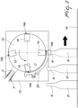
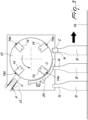
- a rotary capsule dispenser 10 comprises a wheel 12 which is supported rotatably about a horizontal axis by a frame 13 and is turned by motor means (not shown).
- the wheel 12 supports peripherally four sockets 14.
- the sockets 14 are arranged so that their axes lie on a vertical plane that is perpendicular to the axis of the wheel and have an open end 14a.
- the sockets 14 follow one another in receiving respective capsules C from a stack P in a capsule loading position ( Figure 1 ).
- a capsule release position has been reached ( Figure 2 )
- the capsules are expelled pneumatically in succession onto the necks N of a row of bottles B which are advanced below the dispenser 10 by conveyance means, such as a motorized screw feeder or a conveyor belt.
- conveyance means are identified schematically by the numeral 16 in the figures so as to indicate the plane of advancement of the bottles.
- the wheel 12 and the conveyance means 16 move synchronously and continuously, so that the bottles B and the sockets 14 are always moving during the expulsion of the capsule C onto the neck N of the bottle B.
- the sockets 14 are supported so that they can rotate with respect to the wheel 12 about respective horizontal axes which are parallel to the rotation axis of the wheel 12, under the actuation of lever systems which are designed so as to arrange the socket 14 with its open end 14a oriented vertically downward with a certain advance with respect to the capsule release position.
- the open ends 14a of the sockets 14 are directed outward in a substantially radial direction.
- the dispenser 10 is provided with capsule retention means 18, which are adapted to retain the capsules C in the respective sockets 14 up to the moment of expulsion.
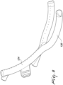
- the capsule retention means comprise a duct 20 which is supplied with pressurized air and which
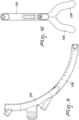
- the tube 24 and the two branches 26, 28 have a rectilinear planar extension ( Figure 7 ) and are interconnected by a V-shaped connecting portion 30.
- the latter has two divergent mirror-like arms 32, 34, which, at the vertex of the V-shape, are connected to the tube 24, while they are connected to the branches 26, 28 respectively at the opposite ends.
- the two branches 26, 28 are parallel to the tube 24.
- the holes are advantageously distributed over all of the duct 20.
- the axes of the holes 22a in the tube 24 are arranged on the central plane Z ( Figure 6 ) of the duct 20 and advantageously are arranged so as to face coaxially the sockets 14, which in this portion of the stroke are oriented in a substantially radial direction.
- the holes 22b, 22c on the two branches 26, 28 converge towards the central plane Z of the duct 20 and are advantageously arranged so that the projection of their axes on the central plane of the duct 20 is substantially coaxial to the sockets 14, following their rule of motion as determined by the above mentioned lever systems.
- the holes 22a on the tube 24 and the holes 22b, 22c on the branches 26, 28 are substantially mutually equidistant.
- the holes on the connecting portion 30 are distributed in a Y-shaped pattern, with a first row of holes 22d the axes of which lie on the central plane Z of the duct 20 in alignment with the holes 22a on the tube 24, and bifurcates into two additional rows of holes 22e, 22f on the arms 32, 34, which advantageously converge toward the central plane of the duct in a manner similar to the holes 22b, 22c on the two branches 26, 28.
- the holes on the connecting portion 30 have a slightly denser distribution to the advantage of effectiveness of the capsule retention action in this region.
- the duct 20 is supplied with pressurized air by means of a first air intake 36 and a second air intake 38.
- the first air intake 36 and the second air intake 38 can be advantageously supplied by two different sources S1, S2, which can be adjusted so as to render the airflow emitted by the holes substantially uniform over the entire duct 20.
- the first air intake 36 is arranged at the free end of the tube 24, while the second air intake 38 is arranged at the opposite end of the tube 24, i.e., directly upstream of the connecting portion 30.
- the duct is also provided with a bracket 40 for anchoring to the frame 13.
- the size, number and the distance between the holes can be chosen on the basis of the dimensions of the duct 20, which in turn may vary as a function of the dimensions of the dispenser 10.
- the holes in the tube 24 and in the branches 26, 28 are mutually equidistant by approximately 12mm, while the holes in the connecting portion 30 are mutually slightly closer. Furthermore, in this embodiment the holes have a diameter of 1.5 mm.
- the duct according to the invention can be advantageously made of synthetic material by additive manufacturing, also known as three-dimensional printing.
- the duct 20 according to the invention makes it possible to retain effectively the capsule C inside the socket 14 until the moment of expulsion, avoiding damage and/or deformations which, in known systems, are caused by contact with mechanical stop elements.
- the fork-like shape of the duct makes it possible to move closer and, in certain circumstances, even fit the socket onto the neck of the bottle without interference.
- a further advantage of the duct according to the invention is that it is highly tolerant with regard to dimensional variations among the capsules, which, as is well-known to the person skilled in the art, normally occur when the production batch is changed and sometimes even within the same batch. This makes it possible to avoid operations for calibrating the sockets when the batch is changed and more generally to maintain a high and constant efficiency even within the same batch.
- the described system has negligible maintenance costs.
- FIGS 8-11 show an alternative embodiment of the invention that is particularly suitable for large-diameter capsules.
- This embodiment differs from the preceding one essentially in that the two branches 126, 128, instead of being parallel to the tube 124, diverge slightly ( Figure 11 ) so as to remain as close as possible to the neck of the bottle up to the moment of capsule insertion.
Landscapes
- Filling Of Jars Or Cans And Processes For Cleaning And Sealing Jars (AREA)
- Medical Preparation Storing Or Oral Administration Devices (AREA)
- Basic Packing Technique (AREA)
Claims (10)
- Ein Kapselspender für Abfüllanlagen, der ein motorisiertes Rad (12) mit horizontaler Achse umfasst, das eine Vielzahl von Buchsen (14) mit einem offenen Ende (14a) trägt, wobei die Buchsen (14) einander im Aufnehmen entsprechender Kapseln (C) in einer Kapsel-Ladeposition und dem Ausstoßen der Kapseln (C) in einer Kapsel-Ausstoßposition folgen, wobei die Buchsen (14) offene Enden (14a) haben, welche zwischen der Kapsel-Ladeposition und der Kapsel-Ausstoßposition nach außen gerichtet sind; dadurch gekennzeichnet, dass er eine mit Druckluft versorgte Leitung (20) umfasst, die- ein bogenförmiges Profil um die Achse des Rades (12) hat und sich außerhalb der Buchsen (14) zwischen der Kapsel-Ladeposition und der Kapsel-Ausstoßposition erstreckt,- eine Röhre (24) umfasst, welche sich an einem unteren Ende in zwei Verzweigungen (26, 28) aufteilt, zwischen denen der Hals (N) der Flasche (B) ausgebildet ist, direkt vor Anbringen der Kapsel (C) eingeführt zu werden, und- mit einer Vielzahl von Löchern (22a, 22b, 22c, 22d, 22e, 22f) versehen ist, die einwärts gerichtet sind, um Luft in Richtung des offenen Endes (14a) der Buchsen (14) zu blasen.
- Der Kapselspender gemäß Anspruch 1, dadurch gekennzeichnet, dass die Röhre (24) und die beiden Verzweigungen (26, 28) durch einen V-förmigen Verbindungsabschnitt (30), der zwei spiegelartig sich verzweigende Arme (32, 34) hat, miteinander verbunden sind.
- Der Kapselspender gemäß Anspruch 1 oder 2, dadurch gekennzeichnet, dass die Röhre (24) einen Teil der Löcher (22a) hat, deren Achsen auf einer zentralen Ebene (Z) der Leitung (20) liegen und die angeordnet sind, um den Buchsen (14) im Wesentlichen koaxial zugewandt zu sein.
- Der Kapselspender gemäß Anspruch 3, dadurch gekennzeichnet, dass die beiden Verzweigungen (26, 28) einen Teil der Löcher (22b, 22c) haben, die zur zentralen Ebene (Z) der Leitung zusammenlaufen und so angeordnet sind, dass die Projektion ihrer Achsen auf die zentrale Ebene (Z) im Wesentlichen koaxial mit den Buchsen (14) ist.
- Der Kapselspender gemäß Anspruch 4, dadurch gekennzeichnet, dass der Teil der Löcher (22d, 22e, 22f) des Verbindungsabschnitts (30) in einem Y-förmigen Muster verteilt ist, wobei die Achsen einer ersten Reihe von Löchern (22d) auf der zentralen Ebene (Z) der Leitung (20) liegen, die sich in zwei weitere Reihen von Löchern (22e, 22f) verzweigt, welche an den Armen (32, 34) geformt sind und zur zentralen Ebene (Z) der Leitung (20) zusammenlaufen.
- Der Kapselspender gemäß einem der Ansprüche 1-5, dadurch gekennzeichnet, dass die Leitung (20) mit zwei Lufteinlässen (36, 38) ausgestattet ist, die wahlweise von zwei verschiedenen Quellen (S1, S2) versorgt werden können.
- Der Kapselspender gemäß Anspruch 6, dadurch gekennzeichnet, dass einer der Lufteinlässe (36) an einem stromaufwärts gelegenen Ende der Röhre (24) angeordnet ist.
- Der Kapselspender gemäß Anspruch 6, dadurch gekennzeichnet, dass einer der Lufteinlässe (38) an einem stromabwärts gelegenen Ende der Röhre (24) angeordnet ist.
- Der Kapselspender gemäß einem der Ansprüche 1-8, dadurch gekennzeichnet, dass die beiden Verzweigungen (26, 28) parallel zu der Röhre (24) sind.
- Der Kapselspender gemäß einem oder mehreren der Ansprüche 1-8, dadurch gekennzeichnet, dass die beiden Verzweigungen (26, 28) divergierend sind.
Applications Claiming Priority (2)
| Application Number | Priority Date | Filing Date | Title |
|---|---|---|---|
| IT102019000016667A IT201900016667A1 (it) | 2019-09-19 | 2019-09-19 | Distributore di capsule rotativo per linee di imbottigliamento |
| PCT/EP2020/075699 WO2021052927A1 (en) | 2019-09-19 | 2020-09-15 | Rotary capsule dispenser for bottling lines |
Publications (2)
| Publication Number | Publication Date |
|---|---|
| EP4031478A1 EP4031478A1 (de) | 2022-07-27 |
| EP4031478B1 true EP4031478B1 (de) | 2023-10-11 |
Family
ID=69468991
Family Applications (1)
| Application Number | Title | Priority Date | Filing Date |
|---|---|---|---|
| EP20771557.4A Active EP4031478B1 (de) | 2019-09-19 | 2020-09-15 | Drehbarer kapselspender für abfüllanlagen |
Country Status (5)
| Country | Link |
|---|---|
| US (1) | US11919762B2 (de) |
| EP (1) | EP4031478B1 (de) |
| AU (1) | AU2020350884B2 (de) |
| IT (1) | IT201900016667A1 (de) |
| WO (1) | WO2021052927A1 (de) |
Family Cites Families (7)
| Publication number | Priority date | Publication date | Assignee | Title |
|---|---|---|---|---|
| GB1129721A (en) * | 1965-02-04 | 1968-10-09 | Betts & Co Ltd | Improved apparatus for automatically locating capsules on the necks of bottles |
| IT1160952B (it) | 1978-07-12 | 1987-03-11 | Robino & Galandrino Snc | Meccansmo per ricevere delle capsule ed applicarle su delle bottiglie |
| US4238267A (en) * | 1978-07-18 | 1980-12-09 | Konstantin Anatole E | Apparatus for producing shrinkable plastic caps |
| EP1831076B1 (de) * | 2004-09-02 | 2013-11-06 | Richard Tomalesky | Vorrichtung und verfahren zum sterilen füllen von behältern |
| US20060144017A1 (en) * | 2005-01-05 | 2006-07-06 | Ruppman Kurt H Sr | Method and apparatus for inerting head space of a capped container |
| ITPD20070345A1 (it) * | 2007-10-19 | 2009-04-20 | Nortan S R L | Bicchiere per gruppo di distribuzione di macchina capsulatrice |
| US8505540B2 (en) * | 2007-11-13 | 2013-08-13 | Apnicure, Inc. | Methods and systems for improving airway patency |
-
2019
- 2019-09-19 IT IT102019000016667A patent/IT201900016667A1/it unknown
-
2020
- 2020-09-15 EP EP20771557.4A patent/EP4031478B1/de active Active
- 2020-09-15 WO PCT/EP2020/075699 patent/WO2021052927A1/en not_active Ceased
- 2020-09-15 AU AU2020350884A patent/AU2020350884B2/en active Active
- 2020-09-15 US US17/761,681 patent/US11919762B2/en active Active
Also Published As
| Publication number | Publication date |
|---|---|
| IT201900016667A1 (it) | 2021-03-19 |
| WO2021052927A1 (en) | 2021-03-25 |
| US11919762B2 (en) | 2024-03-05 |
| AU2020350884A1 (en) | 2022-04-28 |
| EP4031478A1 (de) | 2022-07-27 |
| US20220340405A1 (en) | 2022-10-27 |
| AU2020350884B2 (en) | 2025-09-11 |
Similar Documents
| Publication | Publication Date | Title |
|---|---|---|
| ES2806404T3 (es) | Aparato y método para orientar el cierre de extremo de un recipiente de bebida y aplicación de símbolos en una ubicación predeterminada | |
| US7404277B2 (en) | Beverage bottling plant for filling bottles with a liquid beverage filling material having an information adding station | |
| US9221275B2 (en) | Method of printing a pictorial image onto the circumferential outer surface of beverage bottles and filling beverage bottles in a bottling plant for filling bottles with a liquid beverage filling material in rotary filling machinery and apparatus therefor | |
| EP2980010B1 (de) | Anlage zum Abfüllen und Verschliessen von Behältern | |
| US20100071830A1 (en) | Method of labeling bottles and containers in a bottle or container filling plant, and a bottle or container labeling arrangement therefor | |
| ZA201008351B (en) | A machine and a method for labelling containers | |
| US5123993A (en) | Method and apparatus for the automatic recycling of plastic bottles | |
| WO2008036745A1 (en) | Article alignment apparatus | |
| CN111873636B (zh) | 一种立式安瓿瓶彩喷印字生产线 | |
| JP2011162225A (ja) | 容器払い出し装置 | |
| CA2579247A1 (en) | Beverage bottling plant for filling bottles with a liquid beverage filling material having an information adding station | |
| EP1537025A1 (de) | Verfahren und vorrichtung zum etikettieren einer reihenfolge von behältern mittels einer anzahl von unabhängigen etikettierstationen | |
| CN107530759B (zh) | 用于卷曲制品的方法和设备 | |
| EP4031478B1 (de) | Drehbarer kapselspender für abfüllanlagen | |
| EP3225561B1 (de) | Behälterbehandlungsmaschine und verfahren zum betrieb solch einer maschine | |
| WO2011007370A1 (en) | Method and unit for conveying bottles | |
| US9926180B2 (en) | Capping machine | |
| US7065938B2 (en) | Beverage bottling plant for filling bottles with a liquid beverage filling material, and a container filling plant container information adding station, such as, a labeling station having a gripper arrangement, configured to add information to containers, such as, bottles and cans | |
| EP2927140B1 (de) | Anlage zur Herstellung von gefüllten Behältern mit Trocknungseinheit | |
| JP7582975B2 (ja) | 特に製薬産業におけるボトルを充填する装置のための搬送方法及び搬送システム | |
| EP4234250B1 (de) | Dorn zum drucken von dosen mit hals | |
| US10780714B2 (en) | Mandrel for printing necked cans | |
| EP3826945B1 (de) | Halsführungsvorrichtung für flaschenabfüllanlagen | |
| EP2325133A1 (de) | Behälterverschliessvorrichtung | |
| CN102582898A (zh) | 用于给容器施加弹性膜套的设备和方法 |
Legal Events
| Date | Code | Title | Description |
|---|---|---|---|
| STAA | Information on the status of an ep patent application or granted ep patent |
Free format text: STATUS: UNKNOWN |
|
| STAA | Information on the status of an ep patent application or granted ep patent |
Free format text: STATUS: THE INTERNATIONAL PUBLICATION HAS BEEN MADE |
|
| PUAI | Public reference made under article 153(3) epc to a published international application that has entered the european phase |
Free format text: ORIGINAL CODE: 0009012 |
|
| STAA | Information on the status of an ep patent application or granted ep patent |
Free format text: STATUS: REQUEST FOR EXAMINATION WAS MADE |
|
| 17P | Request for examination filed |
Effective date: 20220412 |
|
| AK | Designated contracting states |
Kind code of ref document: A1 Designated state(s): AL AT BE BG CH CY CZ DE DK EE ES FI FR GB GR HR HU IE IS IT LI LT LU LV MC MK MT NL NO PL PT RO RS SE SI SK SM TR |
|
| DAV | Request for validation of the european patent (deleted) | ||
| DAX | Request for extension of the european patent (deleted) | ||
| GRAP | Despatch of communication of intention to grant a patent |
Free format text: ORIGINAL CODE: EPIDOSNIGR1 |
|
| STAA | Information on the status of an ep patent application or granted ep patent |
Free format text: STATUS: GRANT OF PATENT IS INTENDED |
|
| INTG | Intention to grant announced |
Effective date: 20230425 |
|
| GRAS | Grant fee paid |
Free format text: ORIGINAL CODE: EPIDOSNIGR3 |
|
| GRAA | (expected) grant |
Free format text: ORIGINAL CODE: 0009210 |
|
| STAA | Information on the status of an ep patent application or granted ep patent |
Free format text: STATUS: THE PATENT HAS BEEN GRANTED |
|
| AK | Designated contracting states |
Kind code of ref document: B1 Designated state(s): AL AT BE BG CH CY CZ DE DK EE ES FI FR GB GR HR HU IE IS IT LI LT LU LV MC MK MT NL NO PL PT RO RS SE SI SK SM TR |
|
| REG | Reference to a national code |
Ref country code: GB Ref legal event code: FG4D |
|
| REG | Reference to a national code |
Ref country code: CH Ref legal event code: EP |
|
| REG | Reference to a national code |
Ref country code: DE Ref legal event code: R096 Ref document number: 602020019159 Country of ref document: DE |
|
| REG | Reference to a national code |
Ref country code: IE Ref legal event code: FG4D |
|
| REG | Reference to a national code |
Ref country code: LT Ref legal event code: MG9D |
|
| REG | Reference to a national code |
Ref country code: NL Ref legal event code: MP Effective date: 20231011 |
|
| REG | Reference to a national code |
Ref country code: AT Ref legal event code: MK05 Ref document number: 1620061 Country of ref document: AT Kind code of ref document: T Effective date: 20231011 |
|
| PG25 | Lapsed in a contracting state [announced via postgrant information from national office to epo] |
Ref country code: NL Free format text: LAPSE BECAUSE OF FAILURE TO SUBMIT A TRANSLATION OF THE DESCRIPTION OR TO PAY THE FEE WITHIN THE PRESCRIBED TIME-LIMIT Effective date: 20231011 |
|
| PG25 | Lapsed in a contracting state [announced via postgrant information from national office to epo] |
Ref country code: GR Free format text: LAPSE BECAUSE OF FAILURE TO SUBMIT A TRANSLATION OF THE DESCRIPTION OR TO PAY THE FEE WITHIN THE PRESCRIBED TIME-LIMIT Effective date: 20240112 |
|
| PG25 | Lapsed in a contracting state [announced via postgrant information from national office to epo] |
Ref country code: IS Free format text: LAPSE BECAUSE OF FAILURE TO SUBMIT A TRANSLATION OF THE DESCRIPTION OR TO PAY THE FEE WITHIN THE PRESCRIBED TIME-LIMIT Effective date: 20240211 |
|
| PG25 | Lapsed in a contracting state [announced via postgrant information from national office to epo] |
Ref country code: LT Free format text: LAPSE BECAUSE OF FAILURE TO SUBMIT A TRANSLATION OF THE DESCRIPTION OR TO PAY THE FEE WITHIN THE PRESCRIBED TIME-LIMIT Effective date: 20231011 |
|
| PG25 | Lapsed in a contracting state [announced via postgrant information from national office to epo] |
Ref country code: AT Free format text: LAPSE BECAUSE OF FAILURE TO SUBMIT A TRANSLATION OF THE DESCRIPTION OR TO PAY THE FEE WITHIN THE PRESCRIBED TIME-LIMIT Effective date: 20231011 |
|
| PG25 | Lapsed in a contracting state [announced via postgrant information from national office to epo] |
Ref country code: ES Free format text: LAPSE BECAUSE OF FAILURE TO SUBMIT A TRANSLATION OF THE DESCRIPTION OR TO PAY THE FEE WITHIN THE PRESCRIBED TIME-LIMIT Effective date: 20231011 |
|
| PG25 | Lapsed in a contracting state [announced via postgrant information from national office to epo] |
Ref country code: LT Free format text: LAPSE BECAUSE OF FAILURE TO SUBMIT A TRANSLATION OF THE DESCRIPTION OR TO PAY THE FEE WITHIN THE PRESCRIBED TIME-LIMIT Effective date: 20231011 Ref country code: IS Free format text: LAPSE BECAUSE OF FAILURE TO SUBMIT A TRANSLATION OF THE DESCRIPTION OR TO PAY THE FEE WITHIN THE PRESCRIBED TIME-LIMIT Effective date: 20240211 Ref country code: GR Free format text: LAPSE BECAUSE OF FAILURE TO SUBMIT A TRANSLATION OF THE DESCRIPTION OR TO PAY THE FEE WITHIN THE PRESCRIBED TIME-LIMIT Effective date: 20240112 Ref country code: ES Free format text: LAPSE BECAUSE OF FAILURE TO SUBMIT A TRANSLATION OF THE DESCRIPTION OR TO PAY THE FEE WITHIN THE PRESCRIBED TIME-LIMIT Effective date: 20231011 Ref country code: BG Free format text: LAPSE BECAUSE OF FAILURE TO SUBMIT A TRANSLATION OF THE DESCRIPTION OR TO PAY THE FEE WITHIN THE PRESCRIBED TIME-LIMIT Effective date: 20240111 Ref country code: AT Free format text: LAPSE BECAUSE OF FAILURE TO SUBMIT A TRANSLATION OF THE DESCRIPTION OR TO PAY THE FEE WITHIN THE PRESCRIBED TIME-LIMIT Effective date: 20231011 Ref country code: PT Free format text: LAPSE BECAUSE OF FAILURE TO SUBMIT A TRANSLATION OF THE DESCRIPTION OR TO PAY THE FEE WITHIN THE PRESCRIBED TIME-LIMIT Effective date: 20240212 |
|
| PG25 | Lapsed in a contracting state [announced via postgrant information from national office to epo] |
Ref country code: SE Free format text: LAPSE BECAUSE OF FAILURE TO SUBMIT A TRANSLATION OF THE DESCRIPTION OR TO PAY THE FEE WITHIN THE PRESCRIBED TIME-LIMIT Effective date: 20231011 Ref country code: RS Free format text: LAPSE BECAUSE OF FAILURE TO SUBMIT A TRANSLATION OF THE DESCRIPTION OR TO PAY THE FEE WITHIN THE PRESCRIBED TIME-LIMIT Effective date: 20231011 Ref country code: PL Free format text: LAPSE BECAUSE OF FAILURE TO SUBMIT A TRANSLATION OF THE DESCRIPTION OR TO PAY THE FEE WITHIN THE PRESCRIBED TIME-LIMIT Effective date: 20231011 Ref country code: NO Free format text: LAPSE BECAUSE OF FAILURE TO SUBMIT A TRANSLATION OF THE DESCRIPTION OR TO PAY THE FEE WITHIN THE PRESCRIBED TIME-LIMIT Effective date: 20240111 Ref country code: LV Free format text: LAPSE BECAUSE OF FAILURE TO SUBMIT A TRANSLATION OF THE DESCRIPTION OR TO PAY THE FEE WITHIN THE PRESCRIBED TIME-LIMIT Effective date: 20231011 Ref country code: HR Free format text: LAPSE BECAUSE OF FAILURE TO SUBMIT A TRANSLATION OF THE DESCRIPTION OR TO PAY THE FEE WITHIN THE PRESCRIBED TIME-LIMIT Effective date: 20231011 |
|
| PG25 | Lapsed in a contracting state [announced via postgrant information from national office to epo] |
Ref country code: DK Free format text: LAPSE BECAUSE OF FAILURE TO SUBMIT A TRANSLATION OF THE DESCRIPTION OR TO PAY THE FEE WITHIN THE PRESCRIBED TIME-LIMIT Effective date: 20231011 |
|
| REG | Reference to a national code |
Ref country code: DE Ref legal event code: R097 Ref document number: 602020019159 Country of ref document: DE |
|
| PG25 | Lapsed in a contracting state [announced via postgrant information from national office to epo] |
Ref country code: CZ Free format text: LAPSE BECAUSE OF FAILURE TO SUBMIT A TRANSLATION OF THE DESCRIPTION OR TO PAY THE FEE WITHIN THE PRESCRIBED TIME-LIMIT Effective date: 20231011 |
|
| PG25 | Lapsed in a contracting state [announced via postgrant information from national office to epo] |
Ref country code: SK Free format text: LAPSE BECAUSE OF FAILURE TO SUBMIT A TRANSLATION OF THE DESCRIPTION OR TO PAY THE FEE WITHIN THE PRESCRIBED TIME-LIMIT Effective date: 20231011 |
|
| PG25 | Lapsed in a contracting state [announced via postgrant information from national office to epo] |
Ref country code: SM Free format text: LAPSE BECAUSE OF FAILURE TO SUBMIT A TRANSLATION OF THE DESCRIPTION OR TO PAY THE FEE WITHIN THE PRESCRIBED TIME-LIMIT Effective date: 20231011 Ref country code: SK Free format text: LAPSE BECAUSE OF FAILURE TO SUBMIT A TRANSLATION OF THE DESCRIPTION OR TO PAY THE FEE WITHIN THE PRESCRIBED TIME-LIMIT Effective date: 20231011 Ref country code: RO Free format text: LAPSE BECAUSE OF FAILURE TO SUBMIT A TRANSLATION OF THE DESCRIPTION OR TO PAY THE FEE WITHIN THE PRESCRIBED TIME-LIMIT Effective date: 20231011 Ref country code: EE Free format text: LAPSE BECAUSE OF FAILURE TO SUBMIT A TRANSLATION OF THE DESCRIPTION OR TO PAY THE FEE WITHIN THE PRESCRIBED TIME-LIMIT Effective date: 20231011 Ref country code: DK Free format text: LAPSE BECAUSE OF FAILURE TO SUBMIT A TRANSLATION OF THE DESCRIPTION OR TO PAY THE FEE WITHIN THE PRESCRIBED TIME-LIMIT Effective date: 20231011 Ref country code: CZ Free format text: LAPSE BECAUSE OF FAILURE TO SUBMIT A TRANSLATION OF THE DESCRIPTION OR TO PAY THE FEE WITHIN THE PRESCRIBED TIME-LIMIT Effective date: 20231011 |
|
| P01 | Opt-out of the competence of the unified patent court (upc) registered |
Free format text: CASE NUMBER: APP_40203/2024 Effective date: 20240705 |
|
| PLBE | No opposition filed within time limit |
Free format text: ORIGINAL CODE: 0009261 |
|
| STAA | Information on the status of an ep patent application or granted ep patent |
Free format text: STATUS: NO OPPOSITION FILED WITHIN TIME LIMIT |
|
| 26N | No opposition filed |
Effective date: 20240712 |
|
| PG25 | Lapsed in a contracting state [announced via postgrant information from national office to epo] |
Ref country code: SI Free format text: LAPSE BECAUSE OF FAILURE TO SUBMIT A TRANSLATION OF THE DESCRIPTION OR TO PAY THE FEE WITHIN THE PRESCRIBED TIME-LIMIT Effective date: 20231011 |
|
| PG25 | Lapsed in a contracting state [announced via postgrant information from national office to epo] |
Ref country code: SI Free format text: LAPSE BECAUSE OF FAILURE TO SUBMIT A TRANSLATION OF THE DESCRIPTION OR TO PAY THE FEE WITHIN THE PRESCRIBED TIME-LIMIT Effective date: 20231011 |
|
| REG | Reference to a national code |
Ref country code: DE Ref legal event code: R119 Ref document number: 602020019159 Country of ref document: DE |
|
| PG25 | Lapsed in a contracting state [announced via postgrant information from national office to epo] |
Ref country code: MC Free format text: LAPSE BECAUSE OF FAILURE TO SUBMIT A TRANSLATION OF THE DESCRIPTION OR TO PAY THE FEE WITHIN THE PRESCRIBED TIME-LIMIT Effective date: 20231011 |
|
| REG | Reference to a national code |
Ref country code: CH Ref legal event code: PL |
|
| PG25 | Lapsed in a contracting state [announced via postgrant information from national office to epo] |
Ref country code: LU Free format text: LAPSE BECAUSE OF NON-PAYMENT OF DUE FEES Effective date: 20240915 |
|
| PG25 | Lapsed in a contracting state [announced via postgrant information from national office to epo] |
Ref country code: DE Free format text: LAPSE BECAUSE OF NON-PAYMENT OF DUE FEES Effective date: 20250401 |
|
| REG | Reference to a national code |
Ref country code: BE Ref legal event code: MM Effective date: 20240930 |
|
| PG25 | Lapsed in a contracting state [announced via postgrant information from national office to epo] |
Ref country code: BE Free format text: LAPSE BECAUSE OF NON-PAYMENT OF DUE FEES Effective date: 20240930 |
|
| PG25 | Lapsed in a contracting state [announced via postgrant information from national office to epo] |
Ref country code: CH Free format text: LAPSE BECAUSE OF NON-PAYMENT OF DUE FEES Effective date: 20240930 |
|
| PG25 | Lapsed in a contracting state [announced via postgrant information from national office to epo] |
Ref country code: IE Free format text: LAPSE BECAUSE OF NON-PAYMENT OF DUE FEES Effective date: 20240915 |
|
| PG25 | Lapsed in a contracting state [announced via postgrant information from national office to epo] |
Ref country code: FI Free format text: LAPSE BECAUSE OF FAILURE TO SUBMIT A TRANSLATION OF THE DESCRIPTION OR TO PAY THE FEE WITHIN THE PRESCRIBED TIME-LIMIT Effective date: 20231011 |
|
| PGFP | Annual fee paid to national office [announced via postgrant information from national office to epo] |
Ref country code: IT Payment date: 20250620 Year of fee payment: 6 |
|
| PGFP | Annual fee paid to national office [announced via postgrant information from national office to epo] |
Ref country code: GB Payment date: 20250918 Year of fee payment: 6 |
|
| PGFP | Annual fee paid to national office [announced via postgrant information from national office to epo] |
Ref country code: FR Payment date: 20250918 Year of fee payment: 6 |
|
| PG25 | Lapsed in a contracting state [announced via postgrant information from national office to epo] |
Ref country code: CY Free format text: LAPSE BECAUSE OF FAILURE TO SUBMIT A TRANSLATION OF THE DESCRIPTION OR TO PAY THE FEE WITHIN THE PRESCRIBED TIME-LIMIT; INVALID AB INITIO Effective date: 20200915 |
|
| PG25 | Lapsed in a contracting state [announced via postgrant information from national office to epo] |
Ref country code: HU Free format text: LAPSE BECAUSE OF FAILURE TO SUBMIT A TRANSLATION OF THE DESCRIPTION OR TO PAY THE FEE WITHIN THE PRESCRIBED TIME-LIMIT; INVALID AB INITIO Effective date: 20200915 |