EP4031333B1 - Betätigungsvorrichtung für roboter - Google Patents
Betätigungsvorrichtung für roboter Download PDFInfo
- Publication number
- EP4031333B1 EP4031333B1 EP20789259.7A EP20789259A EP4031333B1 EP 4031333 B1 EP4031333 B1 EP 4031333B1 EP 20789259 A EP20789259 A EP 20789259A EP 4031333 B1 EP4031333 B1 EP 4031333B1
- Authority
- EP
- European Patent Office
- Prior art keywords
- designed
- actuator
- output
- robotic device
- planetary gear
- Prior art date
- Legal status (The legal status is an assumption and is not a legal conclusion. Google has not performed a legal analysis and makes no representation as to the accuracy of the status listed.)
- Active
Links
Images


Classifications
-
- B—PERFORMING OPERATIONS; TRANSPORTING
- B25—HAND TOOLS; PORTABLE POWER-DRIVEN TOOLS; MANIPULATORS
- B25J—MANIPULATORS; CHAMBERS PROVIDED WITH MANIPULATION DEVICES
- B25J9/00—Programme-controlled manipulators
- B25J9/10—Programme-controlled manipulators characterised by positioning means for manipulator elements
- B25J9/102—Gears specially adapted therefor, e.g. reduction gears
-
- B—PERFORMING OPERATIONS; TRANSPORTING
- B25—HAND TOOLS; PORTABLE POWER-DRIVEN TOOLS; MANIPULATORS
- B25J—MANIPULATORS; CHAMBERS PROVIDED WITH MANIPULATION DEVICES
- B25J15/00—Gripping heads and other end effectors
- B25J15/0009—Gripping heads and other end effectors comprising multi-articulated fingers, e.g. resembling a human hand
-
- B—PERFORMING OPERATIONS; TRANSPORTING
- B25—HAND TOOLS; PORTABLE POWER-DRIVEN TOOLS; MANIPULATORS
- B25J—MANIPULATORS; CHAMBERS PROVIDED WITH MANIPULATION DEVICES
- B25J9/00—Programme-controlled manipulators
- B25J9/10—Programme-controlled manipulators characterised by positioning means for manipulator elements
- B25J9/102—Gears specially adapted therefor, e.g. reduction gears
- B25J9/103—Gears specially adapted therefor, e.g. reduction gears with backlash-preventing means
-
- A—HUMAN NECESSITIES
- A61—MEDICAL OR VETERINARY SCIENCE; HYGIENE
- A61F—FILTERS IMPLANTABLE INTO BLOOD VESSELS; PROSTHESES; DEVICES PROVIDING PATENCY TO, OR PREVENTING COLLAPSING OF, TUBULAR STRUCTURES OF THE BODY, e.g. STENTS; ORTHOPAEDIC, NURSING OR CONTRACEPTIVE DEVICES; FOMENTATION; TREATMENT OR PROTECTION OF EYES OR EARS; BANDAGES, DRESSINGS OR ABSORBENT PADS; FIRST-AID KITS
- A61F2/00—Filters implantable into blood vessels; Prostheses, i.e. artificial substitutes or replacements for parts of the body; Appliances for connecting them with the body; Devices providing patency to, or preventing collapsing of, tubular structures of the body, e.g. stents
- A61F2/50—Prostheses not implantable in the body
- A61F2/68—Operating or control means
- A61F2002/6836—Gears specially adapted therefor, e.g. reduction gears
-
- A—HUMAN NECESSITIES
- A61—MEDICAL OR VETERINARY SCIENCE; HYGIENE
- A61F—FILTERS IMPLANTABLE INTO BLOOD VESSELS; PROSTHESES; DEVICES PROVIDING PATENCY TO, OR PREVENTING COLLAPSING OF, TUBULAR STRUCTURES OF THE BODY, e.g. STENTS; ORTHOPAEDIC, NURSING OR CONTRACEPTIVE DEVICES; FOMENTATION; TREATMENT OR PROTECTION OF EYES OR EARS; BANDAGES, DRESSINGS OR ABSORBENT PADS; FIRST-AID KITS
- A61F2/00—Filters implantable into blood vessels; Prostheses, i.e. artificial substitutes or replacements for parts of the body; Appliances for connecting them with the body; Devices providing patency to, or preventing collapsing of, tubular structures of the body, e.g. stents
- A61F2/50—Prostheses not implantable in the body
- A61F2/68—Operating or control means
- A61F2002/6845—Clutches
-
- F—MECHANICAL ENGINEERING; LIGHTING; HEATING; WEAPONS; BLASTING
- F16—ENGINEERING ELEMENTS AND UNITS; GENERAL MEASURES FOR PRODUCING AND MAINTAINING EFFECTIVE FUNCTIONING OF MACHINES OR INSTALLATIONS; THERMAL INSULATION IN GENERAL
- F16H—GEARING
- F16H1/00—Toothed gearings for conveying rotary motion
- F16H1/28—Toothed gearings for conveying rotary motion with gears having orbital motion
- F16H1/32—Toothed gearings for conveying rotary motion with gears having orbital motion in which the central axis of the gearing lies inside the periphery of an orbital gear
- F16H2001/325—Toothed gearings for conveying rotary motion with gears having orbital motion in which the central axis of the gearing lies inside the periphery of an orbital gear comprising a carrier with pins guiding at least one orbital gear with circular holes
Definitions
- This invention relates to an actuator for robotic devices of the type specified in the preamble of the first claim.
- the invention concerns an actuator designed to be used for a robotic device e.g. anthropomorphic (such as those typical of the prosthetics sector for controlling a prosthesis such as that of an artificial prosthetic/myoelectric hand capable of reproducing the movements of a human hand) or non-anthropomorphic (e.g. suitable for material-handling or pick and place movements), such as grippers.
- a robotic device e.g. anthropomorphic (such as those typical of the prosthetics sector for controlling a prosthesis such as that of an artificial prosthetic/myoelectric hand capable of reproducing the movements of a human hand) or non-anthropomorphic (e.g. suitable for material-handling or pick and place movements), such as grippers.
- anthropomorphic such as those typical of the prosthetics sector for controlling a prosthesis such as that of an artificial prosthetic/myoelectric hand capable of reproducing the movements of a human hand
- non-anthropomorphic e.g. suitable for material-handling or pick and place movements
- anthropomorphic devices and, in particular, prostheses consist of artificial devices that reproduce a part of a body (animal or especially human) such as a robot, a robotic arm, and, preferably, a device replacing a missing part of the body and, more preferably, a prosthetic hand.
- Prostheses are mainly divided into passive and active ones.
- Passive prostheses are used to replace an amputated body part in order to restore bodily integrity with particular attention to aesthetics. These prostheses are characterised by a stiff, non-motorised structure. They are not able to grip things. Active prostheses, and especially hands, have mechanical and/or electronic components that, by articulating the parts forming the prosthesis, can reproduce poses/grips; and one or more actuators designed to control the motion of said mechanical components usually through one or more cables moved by the actuator. Specifically, active prostheses can include a number of actuators equal to the number of degrees of freedom or be under-implemented and, therefore, have fewer actuators than the number of degrees of freedom.
- Non-anthropomorphic devices and, in particular, industrial robots e.g. robotic arms, grippers, end effectors, or other similar devices designed to interact with the environment and mostly used to handle/manipulate an object or perform an operation usually in an industrial environment
- industrial robots e.g. robotic arms, grippers, end effectors, or other similar devices designed to interact with the environment and mostly used to handle/manipulate an object or perform an operation usually in an industrial environment
- the actuators of non-anthropomorphic devices therefore consist of mechanical/electronic components that, by articulating the parts, enable the device to manipulate an object.
- actuators basically consist of motors, usually servomotors, to the output shaft of which a pulley is attached, which controls an at least partial actuation cable of the prosthesis. Examples of actuators are described in US2016106615A1 , US2012325040A1 , JP2014163440A , WO2007076763 , WO201411184 , EP3457995 , and EP0045818 .
- the technical task underlying this invention is to devise a prosthetic actuator capable of basically overcoming at least part of the above-mentioned drawbacks.
- an important purpose of the invention is to make a prosthesis characterised by great comfort of use and, therefore, one that fully satisfies a patient's expectations.
- the measures, values, shapes and geometric references (such as perpendicularity and parallelism), when used with words like “about” or other similar terms such as “approximately” or “substantially”, are to be understood as except for measurement errors or inaccuracies due to production and/or manufacturing errors and, above all, except for a slight divergence from the value, measure, shape or geometric reference with which it is associated. For example, if associated with a value, such terms preferably indicate a divergence of no more than 10% from the value itself.
- processing means such as "processing”, “computing”, “determination”, “calculation”, or similar, are considered to refer to the action and/or processes of a computer or similar electronic calculation device, which manipulates and/or transforms data represented as physical, such as electronic magnitudes of registers of an IT system and/or memories, other data similarly represented as physical quantities within IT systems, registers or other information memorization, transmission or display devices.
- the reference number 1 globally denotes the actuator according to the invention.
- a robotic device 10 preferably consisting of a manipulator, for example an anthropomorphic or non-anthropomorphic manipulator.
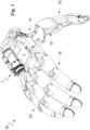
- the robotic device 10 can be a robotic hand or, preferably, a prosthesis and, more preferably, a limb or a hand as illustrated in Fig. 1 .
- the robotic device 10 may comprise, at least one actuator 1, a base body 11 to support at least one actuator 1; one or more mobile components 12 designed to be moved; a transmission kinematic mechanism 13 designed to receive the motion from the actuator 1 and to transmit it to one or more components.
- the robotic device 10 may comprise, in addition, a connection designed to enable the robotic device 10 to be attached to the patient's body.
- the robotic device 10 in the non-limiting example in Fig. 1 , may consist of a prosthesis and, specifically, a prosthetic hand, conveniently under-implemented, capable of reproducing the movements of a human hand. Said hand and, therefore, the robotic device 10 may comprise at least one finger (preferably five fingers); a base body 11; and at least one transmission kinematic mechanism 13 designed to receive the motion from the actuator 1 and transmit it to one or more fingers.
- the actuator is designed to be attached integrally to the robotic device 10. For example, in the case of a hand, it is integral with the base body 11.
- the base body 11 is designed to be attached to an external element such as a robotic arm or a human limb.
- the base body 11 defines a main extension surface. It consists of the palm of the under-implemented hand 1.
- Each finger may comprise one or more phalanges, each of which consists of a mobile component 12.
- one finger may comprise one phalange (i.e. a first mobile component 12) proximal to the base body 11 and one phalange (i.e. a second mobile component 12) distal to the base body 11; and in some cases an intermediate phalange (i.e. a third mobile component 12) having an end hinged to the proximal phalange and the opposite end hinged to the distal phalange.
- the actuator 1 defines at least one motion output and, in particular, a first output 1a and a second output 1b.
- the outputs 1a and 1b preferably define, between them, a motion of a different modulus (for example different speed and ⁇ or acceleration) and, specifically, the same direction.
- a different modulus for example different speed and ⁇ or acceleration
- the transmission kinematic mechanism 13 is designed to control the actuation of the robotic device 10 based on the output motion of the actuator 1, i.e. from the outputs 1a and 1b.
- the transmission kinematic mechanism 13 is integral with the base body 11.
- the robotic device 10 may comprise several transmission kinematic mechanisms 13 designed to control the motion of components of the robotic device itself, preferably independently of each other.
- an under-implemented hand may comprise a first transmission kinematic mechanism 13 designed to receive the motion from the first output 1a and controlling a first part of the mobile components 12; and a second transmission kinematic mechanism 13 designed to receive the motion from the second output 1b and controlling a second part of the mobile components 12 at least to complement said first part.
- the under-implemented hand may comprise just one transmission kinematic mechanism 13 actuating all the mobile components 12.
- the outputs 1a and 1b define, between them, a motion of a different modulus and, specifically, the same direction.
- a transmission kinematic mechanism 13 is described in PCT/IB2019/053682.
- the robotic device 10 comprises a first transmission cable to transmit motion from the first output 1a to the first control cable described in PCT/IB2019/053682 and a second transmission cable designed to transmit motion from the second output 1b to said first control cable.
- the transmission kinematic mechanism 13 can, therefore, comprise a connection device designed to enable each transmission cable to control the first control cable and, therefore, the mobile components 12 as described in PCT/IB2019/053682.
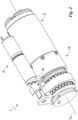
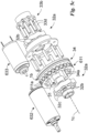
- the actuator 1 defines a longitudinal axis 1c conveniently barycentric to the actuator 1.
- the actuator 1 may comprise a motor 2, conveniently an electric one, designed to generate the motion; and a planetary gear train 3 designed to transmit the motion from the motor 2 to the outputs 1a and 1b; and a crankcase 4 housing at least part of the actuation group.
- the motor 2 defines a rotary motion along the longitudinal axis 1c.
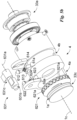
- the planetary gear train 3 comprises, briefly, a sun gear 31 designed to receive the motion from the motor 2; a satellite group 32; a planetary gear train 33 defining the first output 1a; and a crown 34 defining the second output 1b.
- the sun gear 31 may comprise a shaft conveniently having the longitudinal axis 1c as its axis.
- the satellite group 32 is kinematically interposed between the entry of the motion in the planetary gear train 3 (the sun gear 31) and the output of the motion from the planetary gear train 3, consisting of the planetary gear train 33 (first output 1a) or in the crown 34 (second output 1b) as described below.
- the satellite group 32 may comprise one or more satellites consisting of wheels led (by friction and/or a toothed coupling) by the sun gear 31 and dragging the planetary gear 33 or crown 34.
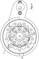
- the planetary gear train 3 is preferably a conveniently cycloid reducer. It can, therefore, as detailed below, exploit one or more cycloid discs (constituting the satellite group 32) in eccentric rotation and having insertion holes for cylinders integral with the planetary gear 33 and having diameters smaller than the cylinders themselves; and outer lobes designed to be engaged with the lobes inside the crown and fewer in number (usually one) than the lobes inside the crown.
- the sun gear 31 may comprise a shaft conveniently comprising at least one cam. More preferably, the sun gear 31 may comprise a shaft at at least two cams equally angularly spaced so as to minimise the vibrations owing to its rotation.
- Each cam is circular with an axis parallel to and separate from the longitudinal axis 1c.
- the sun gear 31 basically has the longitudinal axis 1c as its rotation axis.
- the satellite group 32 may comprise at least one cycloidal disk 32a attached and conveniently integral with the sun gear 31.
- it may comprise, for each cam of the sun gear 31, a cycloidal disk 32a attached to a cam.
- the sun gear 31 may preferably comprise two cams opposite to the longitudinal axis 1c and the satellite group 32 may comprise two cycloidal disks 32a each of which is attached to one of the cams.
- the planetary gear 33 is designed to basically rotate around the longitudinal axis 1c.
- the planetary gear 33 may comprise a rotating body 33a defining the first output 1a; connection means for connecting the rotating body 33a to the satellite group 32; and, in some cases, a support 33b for the rotating body 33b.
- the rotating body 33a may comprise a first pulley 33c including a first throat defining the first output 1a and, in particular, engaging the above-mentioned first transmission cable.
- the support 33b is placed on the opposite side to the rotating body 33a in relation to the satellite group 32 along the longitudinal axis 1c and attached integrally to the rotating body 33a by the connection means.
- Each cycloidal disk 32a may comprise through holes 32b and the connection means comprise pins 33d with a smaller diameter than the through holes 32b.
- the diameter of the pins 33d is basically less than 70% and, specifically, less than 50% of the diameter of the through holes 32b.
- the pins 33d are basically equidistant along the longitudinal axis 1c.
- the pins 33d are basically equally angularly spaced apart.
- the through holes 32b are basically equidistant from the cam axis.
- the through holes 32b are almost equally angularly spaced apart.
- the crown 34 is connected to the satellite group 32 and, in particular, to at least one cycloidal disk 32a (conveniently, just one cycloidal disk 32a) so as to be dragged by it.
- the transmission ratio between the crown 34 and the satellite group 32 is basically less than 1 and, in particular, basically ranges between 1 and 0.5 and, specifically, between 1 and 0.8.
- the crown 34 may comprise, on the inner surface, i.e. facing the satellite group 32, inner lobes 34a and the cycloidal disk 32a may comprise, on the outer surface, i.e. facing the crown 32, outer lobes 32c, designed to strike against the inner lobes 34a, pushing and therefore rotating the crown 34.
- the number of outer lobes 32c is preferably greater, conveniently by one unit, than the number of inner lobes 34a.
- the height of the lobes 32c and/or 34a is such as to enable just a part of the outer lobes 32c to come into contact with the inner lobes 34a.
- the crown 34 may comprise a second throat defining the second output 1b and, in particular, engage the above-mentioned second transmission cable.
- crankcase 4 is designed to remain still during the operation of the power assembly 4.
- It has a first opening 4a for accessing the first output 1a and a second opening 4b for accessing the second output 1b.
- the actuator 1 can, in addition, comprise a supplementary planetary gear train 5 placed between the motor 2 and the planetary gear train 3.
- the supplementary planetary gear train 5 may mainly comprise a supplementary sun gear 51 designed to receive the motion from the motor 2; a supplementary satellite group 52; a supplementary differential case 53; and a supplementary crown 54.
- the supplementary planetary gear train 5 may define a transmission ratio of approximately 3:1.
- the supplementary sun gear 51 consists of the output shaft of the motor 2.
- the supplementary satellite group 52 may comprise one or more satellites, conveniently four, consisting of wheels designed to be led (by toothed coupling or, preferably, friction so as to limit the maximum torque that can be transmitted) by the supplementary sun gear 51 and drag the supplementary planetary gear 53.
- the supplementary crown 54 is integral with the crankcase 4. It therefore remains during the operation of the supplementary planetary gear train 5.
- the supplementary planetary gear 53 is moved by the supplementary satellite group 52 and connected, conveniently integrally, with the sun gear 31 that is, thus, led by it.
- the actuator 1 may comprise one or more supports for the planetary gears 3 and/or 5, bushings, bearings, and other similar elements that are represented in the figures but not numbered.
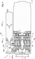
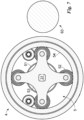
- the actuator 1 may comprise a selector 6 designed to selectively lock the rotation of the planetary gear 33 and of the crown 34 by defining a first operating condition ( Fig. 3 ) in which the crown 34 is locked and the robotic device 10 receives the motion and, thus, is moved by the first output 1a and a second operating condition ( Fig. 4 ) in which the planetary gear 33 is locked and the transmission kinematic mechanism 13 receives the motion from the second output 1b.
- the selector 6 defines a first operating condition in which the transmission kinematic mechanism 13 receives the motion from the first output 1a and a second operating condition in which the transmission kinematic mechanism 13 receives the motion from the second output 1b.
- the selector 6 locks the crown 34 and the first output 1a of the actuator 1 is active and, thus, capable of controlling the robotic device 10. In this first operating condition, the selector 6 locks the crown 34 to the crankcase 4.
- the selector 6 locks the planetary gear 33 and the crankcase 4 has the second output 1b active and, thus, capable of controlling the robotic device 10. In this second operating condition, the selector 6 locks the planetary gear 33 to the crankcase 4.
- the actuator 1 is available only in the first configuration or in the second operating configuration.
- the selector 6 is, thus, designed to only shift between first and second operating configuration. It cannot, therefore, enable the simultaneous locking or moving of the outputs 1a and 1b.
- the selector 6 is attached to the crankcase 4.
- the selector 6 can comprise a first lock 61 for locking the crown 34; a second lock 62 for locking the planetary gear 33; and a control 63 for activating the locks 61 and 62.
- the first lock 61 may comprise a first drum 611 that is integral with the crown 34 and comprising at least one first hole 611a; a first pin 611 attached to the crankcase 4 and designed to be inserted inside the first hole 611a; a first guide 613 attached to the crankcase 4, defining a first locking axis 61a and designed to enable the first pin 611 to slide in relation to the crankcase 4 along the first locking axis 61a; and first return means 614 designed to operate against the entry of the first pin 611 in the first hole 611a.
- the first lock 61 defines a first active position in which the first pin 611 is partially inserted into the first hole 611a locking the crown 34 to the crankcase 4 and a first inactive position in which the first pin 611 is not even partially inserted into the first hole 611a, enabling the crown 34 to rotate in relation to the crankcase 4.
- the first locking axis 61a is basically perpendicular to the longitudinal axis 1c.
- the first drum 611 may comprise a plurality of first holes 611a equally angularly spaced apart.
- the first return means 614 are designed to control the passage of the first pin 611 into a first inactive position. They may comprise a spring, conveniently a compression one.
- the second lock 62 may comprise a second drum 621 that is integral with the planetary gear 33 and comprising at least one second hole 621a; a second pin 622 designed to be inserted into the second hole 621a; a second guide 623 attached to the crankcase 4 defining a second locking axis 62a and designed to enable the second pin 622 to slide along the second locking axis 62a in relation to the crankcase 4; and second return means 624 designed to operate against the entry of the second pin 622 into the second hole 621a.
- the second lock 62 defines a second active position in which the second pin 622 is partially inserted into the second hole 621a, locking the planetary gear 33 to the crankcase 4; and a second inactive position in which the second pin 622 is not even partially inserted into the second hole 621a, enabling the planetary gear 33 to rotate in relation to the crankcase 4.
- the second locking axis 62a is basically perpendicular to the longitudinal axis 1c.
- the second drum 621 may comprise a plurality of second holes 621a equally angularly spaced apart.
- the second return means 624 are designed to control the passage of the second pin 622 into the second inactive position. They may comprise a spring, conveniently a compression one.
- the control 63 is designed to control the locks 621 and 632 at the same time so that they are always conveniently available, and, therefore, to control the passage of one of the locks 621 and 632 into the active position and the other into the inactive position.
- the control 63 may comprise a shaft 631 designed to control the locks 61 and 62 defining a main extension axis 631a; actuation means 632 for rotating the shaft 631 around the main extension axis 631a; and, conveniently, an encoder 633 for said actuator 632.
- the actuation means 632 consist of an electric motor.
- the shaft 631 may comprise a first eccentric 631b to control the passage of the first lock 61 into the first active position and a second eccentric 631c to control the passage of the second lock 62 into the second active position.
- the shaft 631 is designed to rotate around the main extension axis 631a so as to enable each eccentric 631b and 631c to push a pin 611 or 622 into the corresponding hole 611a and 621a in opposition to the return means 614 and 624.
- the actuator 1 may comprise, finally, a card 7 designed to control the operation of the actuator 1 (i.e. of the robotic device 10) and, in particular, of the selector 6 and of the actuation group.
- the actuator 1 is in the first operating condition ( Fig. 3 ). Therefore, the first pin 61, locking the crown 34 to the crankcase 4, is in the active position, while the second lock 62, enabling the planetary gear 33 to rotate in relation to the crankcase 4 and the transmission kinematic mechanism 13 to receive the motion from the first output 1a, is in the second, inactive position.
- the first eccentric 631b pushes the first pin 611, partially inserting it into the first hole 611a in opposition to the first return means 614, while the second eccentric 631c does not push the second pin 622 that, pushed by the second return means 624, is external to the second hole 621a.
- This configuration enables the output motion from the motor 2 to move, conveniently through the supplementary planetary gear train 5, the sun gear 31 that activates the satellite group 32.
- the satellite group 32 since the crown 34 is integral with the crankcase 4, rotates the planetary gear 33.
- the planetary gear 33 rotates, thus, the first output 1a that, through the first transmission cable, activates the transmission kinematic mechanism 13, forcing the under-implemented hand 1 to activate a pose of the robotic device 10.
- the user decides, for example, to perform a different pose with the robotic device 10, he or she controls the passage of the actuator 1 into the second operating condition ( Fig. 4 ) through a myoelectric sensor, or another mechanism designed to send the command to the card 7.
- the card 7 makes the shaft 631 rotate about the main extension axis 631a so as to move the first eccentric 631b away from the first lock 61 and bring the second eccentric 631c against the second lock 62.
- the first return means 614 extract the first pin 611 from the first hole 611a, bringing the first lock 61 into the first inactive position and leaving the crown 34 free to rotate in relation to the crankcase 4.
- the second eccentric 631c pushes, in opposition to the second return means 624, the second pin 622 into the second hole 621a bringing the second lock 62 into the active position and, thus, locking the planetary gear 33 to the crankcase 4.
- the actuator 1 is in the second operating configuration.
- the motor 2 can move, conveniently through the supplementary planetary gear train 5, the sun gear 31 that activates the satellite group 32.
- the satellite group 32 since the planetary gear 33 is integral with the crankcase 4, controls the rotation of the crown 34 and, thus, the second output 1b.
- the second output 1b through the second transmission cable, activates the transmission kinematic mechanism 13, controlling the robotic device 10.
- the actuator 1 is in the first operating condition. Therefore, the first pin 61, locking the crown 34 to the crankcase 4, is in the active position, while the second lock 62 is in the second inactive position, enabling the planetary gear 33 to rotate in relation to the crankcase 4 and, thus, enabling the transmission kinematic mechanism 13 to receive the motion from the first output 1a.
- the first eccentric 631b pushes the first pin 611, that is, thus, partially inserted into the first hole 611a in opposition to the first return means 614, while the second eccentric 631c does not push the second pin 622 that is, thus, pushed by the second return means 614 external to the second hole 621a.
- This configuration enables the output motion from the motor 2 to move, conveniently through the supplementary planetary gear train 5, the sun gear 31 that moves the satellite group 32.
- the satellite group 32 since the crown 34 is integral with the crankcase 4, controls the rotation of the planetary gear 33.
- the planetary gear 33 rotates, thus, the first output 1a that, through the first transmission cable, activates the transmission kinematic mechanism 13.
- the actuator 1 thanks to the presence of two outputs 1a and 1b activated by the same motor 2, makes it possible to obtain a robotic device 10 (conveniently anthropomorphic or non-anthropomorphic) that is more adaptable to the various use needs, notwithstanding the extremely reduced size and weight of the robotic device 10.
- This aspect translates, thus, into a simplicity both of construction and, in particular, of control that, not requiring additional encoders or sensors, define a robotic device 10 (for example a hand) that is very comfortable to use and, thus, totally satisfactory in terms of the user's expectations.
- the actuator 1 makes it possible to use the actuation group remotely; the group can, thus, be placed in the most advantageously free point every time and, thus, have motors better adapted to the application.
- One advantage is the fact that the actuator 1 enables the outputs 1a and 1b to be activated in both rotation directions, broadening the usability of the robotic device 10.
- Another advantage is defined by the detail of the planetary gear train 3 that, since it is composed of an irreversible cycloid system, simplifies the system for selecting the output 1a and 1b.
- the planetary train 3 may consist of a harmonic drive.
Landscapes
- Engineering & Computer Science (AREA)
- Robotics (AREA)
- Mechanical Engineering (AREA)
- Manipulator (AREA)
Claims (9)
- Aktuator (1), der ausgelegt ist, eine Robotervorrichtung (10) zu steuern und der einen ersten Ausgang (1a) sowie einen zweiten Ausgang (1b) definiert; wobei die Ausgänge (1a, 1b) ausgelegt sind, die Bewegung der Robotervorrichtung (10) zu steuern; wobei der Aktuator (1) umfasst:- einen Motor (2), der ausgelegt ist, eine Bewegung zu erzeugen;- ein Planetengetriebezug (3) umfassend∘ ein Sonnenrad (31), das ausgelegt ist, Bewegung von dem Motor (2) aufzunehmen,∘ eine Satellitengruppe (32),∘ ein Planetengetriebe (33), das den ersten Ausgang (1a) definiert, und∘ einen Kranz (34), der den zweiten Ausgang (1b) definiert;- einen Wähler (6), der ausgelegt ist, wahlweise die Drehung des Planetengetriebes (33) und des Kranzes (34) zu sperren, indem ein erster Betriebszustand definiert wird, wobei der Kranz (34) gesperrt wird und die Robotervorrichtung (10) durch den ersten Ausgang (1a) bewegt wird, und ein zweiter Betriebszustand, wobei das Planetengetriebe (33) gesperrt wird und die Robotervorrichtung (10) durch den zweiten Ausgang (1b) bewegt wird;
dadurch gekennzeichnet, dass- die Betätigungsgruppe ein Kurbelgehäuse (4) umfasst; und wobei der Wähler (6) ein erstes Sperrelement (61) zum Sperren des Kranzes (34) an dem Kurbelgehäuse (4); ein zweites Sperrelement (62) zum Sperren des Planetengetriebes (33) an dem Kurbelgehäuse (4); und eine Steuerung (63) zum Aktivieren der Sperrelementen (61, 62) umfasst;
und dass- das erste Sperrelement (61) eine erste Trommel (611) umfasst, die mit dem Kranz (34) befestigt ist und umfassend mindestens eine erste Bohrung (611a); einen ersten Stift (611), der ausgelegt ist, in die erste Bohrung (611a) eingeführt zu werden; eine erste Führung (613), die ausgelegt ist, dem ersten Stift (611) zu ermöglichen, in Bezug auf das Kurbelgehäuse (4) zu gleiten; und erste Rücklaufmittel (614), die ausgelegt sind, in Opposition zu dem Eintritt des ersten Stifts (611) in die erste Bohrung (611a) zu wirken. - Aktuator (1) nach Anspruch 1, wobei das Sonnenrad (31) mindestens eine Nocke umfasst; und wobei die Satellitengruppe (32) mindestens eine Zykloidscheibe (32a) umfasst, die axial an der Nocke befestigt wird.
- Aktuator (1) nach Anspruch 2, wobei das Sonnenrad (31) zwei gleichwinklig beabstandete Nocken umfasst; und wobei die Satellitengruppe (32) zwei Zykloidscheiben (32a) umfasst, von denen jede an einer der Nocken befestigt wird.
- Aktuator (1) nach mindestens einem der Ansprüche 2-3, wobei die mindestens eine Zykloidscheibe (32a) Durchgangsbohrungen (32b) umfasst; wobei das Planetengetriebe (33) einen Drehkörper (33a) umfasst, der den ersten Ausgang (1a) definiert, und Stifte (33d) zum Befestigen des Drehkörpers (33a) an der Satellitengruppe (32); und wobei der Durchmesser der Stifte (33d) kleiner als der Durchmesser der Durchgangsbohrungen (32b) ist.
- Aktuator (1) nach mindestens einem vorhergehenden Anspruch, wobei der Kranz (34) innere Vorsprunge (34a) auf der inneren Oberfläche umfasst; wobei die mindestens eine Zykloidscheibe (32a) äußere Vorsprunge (32c) auf der äußeren Oberfläche umfasst, die ausgelegt sind, zu den inneren Vorsprungen (34a) in Kontrast zu stehen; und wobei die Anzahl der äußeren Vorsprunge (32c) kleiner als die Anzahl der inneren Vorsprunge (34a) ist.
- Aktuator (1) nach Anspruch 1, wobei das zweite Sperrelement (62) eine zweite Trommel (621) umfasst, die an dem Planetengetriebe (33) befestigt ist und mindestens eine zweite Bohrung (621a) umfasst; einen zweiten Stift (622), der ausgelegt ist, in die zweite Bohrung (621a) eingeführt zu werden; eine zweite Führung (623), die ausgelegt ist, dem zweiten Stift (622) zu ermöglichen, in Bezug auf das Kurbelgehäuse (4) zu gleiten; und zweite Rücklaufmittel (624), um in Opposition zu dem Eintritt des zweiten Stifts (622) in die zweite Bohrung (621a) zu wirken.
- Robotervorrichtung (10) umfassend mindestens einen Aktuator (1) nach einem oder mehreren der vorhergehenden Ansprüche und einen kinematischen Übertragungsmechanismus (13), der ausgelegt ist, die Betätigung der Robotervorrichtung (10) basierend auf der Ausgangsbewegung des Aktuators (1) zu steuern und wobei in dem ersten Betriebszustand der kinematische Übertragungsmechanismus (13) die Bewegung von dem ersten Ausgang (4a) empfängt und in einem zweiten Betriebszustand wobei der kinematische Übertragungsmechanismus die Bewegung von dem zweiten Ausgang (4b) empfängt.
- Robotervorrichtung (10) nach dem vorhergehenden Anspruch, wobei die Robotervorrichtung (10) ein Manipulator ist.
- Robotervorrichtung (10) nach dem vorhergehenden Anspruch, wobei die Robotervorrichtung (10) eine Roboterhand ist.
Applications Claiming Priority (2)
| Application Number | Priority Date | Filing Date | Title |
|---|---|---|---|
| IT201900016631 | 2019-09-18 | ||
| PCT/IB2020/058618 WO2021053539A1 (en) | 2019-09-18 | 2020-09-16 | Actuator for robotic devices |
Publications (3)
| Publication Number | Publication Date |
|---|---|
| EP4031333A1 EP4031333A1 (de) | 2022-07-27 |
| EP4031333B1 true EP4031333B1 (de) | 2025-02-19 |
| EP4031333C0 EP4031333C0 (de) | 2025-02-19 |
Family
ID=69468986
Family Applications (1)
| Application Number | Title | Priority Date | Filing Date |
|---|---|---|---|
| EP20789259.7A Active EP4031333B1 (de) | 2019-09-18 | 2020-09-16 | Betätigungsvorrichtung für roboter |
Country Status (2)
| Country | Link |
|---|---|
| EP (1) | EP4031333B1 (de) |
| WO (1) | WO2021053539A1 (de) |
Families Citing this family (1)
| Publication number | Priority date | Publication date | Assignee | Title |
|---|---|---|---|---|
| CN116442276A (zh) * | 2023-04-10 | 2023-07-18 | 深圳市默启文化科技有限公司 | 一种机器人混合减速伺服关节 |
Family Cites Families (3)
| Publication number | Priority date | Publication date | Assignee | Title |
|---|---|---|---|---|
| JP5849456B2 (ja) * | 2011-06-23 | 2016-01-27 | セイコーエプソン株式会社 | 減速機、ロボットハンド、ロボット、及び、電子機器 |
| JP2014163440A (ja) * | 2013-02-25 | 2014-09-08 | Seiko Epson Corp | 減速機、ロボット、ロボットハンド、搬送機、電子部品搬送装置およびギアドモーター |
| KR102117079B1 (ko) * | 2014-10-20 | 2020-05-29 | 삼성전자주식회사 | 구동 모듈, 구동 모듈을 포함하는 운동 보조 장치 및 운동 보조 장치의 제어 방법 |
-
2020
- 2020-09-16 EP EP20789259.7A patent/EP4031333B1/de active Active
- 2020-09-16 WO PCT/IB2020/058618 patent/WO2021053539A1/en not_active Ceased
Also Published As
| Publication number | Publication date |
|---|---|
| EP4031333A1 (de) | 2022-07-27 |
| WO2021053539A1 (en) | 2021-03-25 |
| EP4031333C0 (de) | 2025-02-19 |
Similar Documents
| Publication | Publication Date | Title |
|---|---|---|
| US12070282B2 (en) | Methods, systems, and devices relating to force control surgical systems | |
| US10618182B2 (en) | Underactuated mechanical finger capable of linear motion with compensatory displacement, mechanical gripper and robot containing the same | |
| CN110520256B (zh) | 欠致动机器人手 | |
| EP2919948B1 (de) | Handsteuerungsvorrichtung | |
| JP3356706B2 (ja) | 機械的に巧みな握持を行なう方法 | |
| US20170360522A1 (en) | Articulated handle for mechanical telemanipulator | |
| JPS58132490A (ja) | 角度伝達機構 | |
| US20130030550A1 (en) | Modular human hand prosthesis with modular, mechanically independent finger modules | |
| GB2519993A (en) | Robotic hand | |
| US10899003B2 (en) | Systems and methods for tendon-driven robotic mechanisms | |
| WO2017154254A1 (ja) | 把持ロボット及びロボットハンドの制御方法 | |
| EP4031333B1 (de) | Betätigungsvorrichtung für roboter | |
| Jin et al. | LISA Hand: Indirect self-adaptive robotic hand for robust grasping and simplicity | |
| EP3790513B1 (de) | Unterbetätigte handprothese | |
| Lovchik et al. | Design of the NASA Robonaut hand | |
| Nurpeissova et al. | An open-source mechanical design of alaris hand: A 6-dof anthropomorphic robotic hand | |
| WO2021107819A1 (ru) | Контроллер оператора для управления роботохирургическим комплексом | |
| CN110772325A (zh) | 手柄及主操作台 | |
| Neha et al. | Design Issues in Multi-finger Robotic Hands: An Overview | |
| US20230029226A1 (en) | Spherical Dexterous Hand for Object Grasping and Within-Hand Manipulation | |
| KR20230037045A (ko) | 무제한-롤을 제공하는 핸들 조립체 | |
| JP2022527659A (ja) | ロボットハンド | |
| Ko et al. | Design of an underactuated robot hand based on displacement-force conversion mechanism | |
| EP3790514B1 (de) | Fingerprothese | |
| Luo et al. | Analysis and design for changing finger posture in a robotic hand |
Legal Events
| Date | Code | Title | Description |
|---|---|---|---|
| STAA | Information on the status of an ep patent application or granted ep patent |
Free format text: STATUS: UNKNOWN |
|
| STAA | Information on the status of an ep patent application or granted ep patent |
Free format text: STATUS: THE INTERNATIONAL PUBLICATION HAS BEEN MADE |
|
| PUAI | Public reference made under article 153(3) epc to a published international application that has entered the european phase |
Free format text: ORIGINAL CODE: 0009012 |
|
| STAA | Information on the status of an ep patent application or granted ep patent |
Free format text: STATUS: REQUEST FOR EXAMINATION WAS MADE |
|
| 17P | Request for examination filed |
Effective date: 20220207 |
|
| AK | Designated contracting states |
Kind code of ref document: A1 Designated state(s): AL AT BE BG CH CY CZ DE DK EE ES FI FR GB GR HR HU IE IS IT LI LT LU LV MC MK MT NL NO PL PT RO RS SE SI SK SM TR |
|
| DAV | Request for validation of the european patent (deleted) | ||
| DAX | Request for extension of the european patent (deleted) | ||
| GRAP | Despatch of communication of intention to grant a patent |
Free format text: ORIGINAL CODE: EPIDOSNIGR1 |
|
| STAA | Information on the status of an ep patent application or granted ep patent |
Free format text: STATUS: GRANT OF PATENT IS INTENDED |
|
| INTG | Intention to grant announced |
Effective date: 20241017 |
|
| GRAS | Grant fee paid |
Free format text: ORIGINAL CODE: EPIDOSNIGR3 |
|
| GRAA | (expected) grant |
Free format text: ORIGINAL CODE: 0009210 |
|
| STAA | Information on the status of an ep patent application or granted ep patent |
Free format text: STATUS: THE PATENT HAS BEEN GRANTED |
|
| AK | Designated contracting states |
Kind code of ref document: B1 Designated state(s): AL AT BE BG CH CY CZ DE DK EE ES FI FR GB GR HR HU IE IS IT LI LT LU LV MC MK MT NL NO PL PT RO RS SE SI SK SM TR |
|
| REG | Reference to a national code |
Ref country code: GB Ref legal event code: FG4D |
|
| REG | Reference to a national code |
Ref country code: CH Ref legal event code: EP |
|
| REG | Reference to a national code |
Ref country code: IE Ref legal event code: FG4D |
|
| REG | Reference to a national code |
Ref country code: DE Ref legal event code: R096 Ref document number: 602020046375 Country of ref document: DE |
|
| U01 | Request for unitary effect filed |
Effective date: 20250228 |
|
| U07 | Unitary effect registered |
Designated state(s): AT BE BG DE DK EE FI FR IT LT LU LV MT NL PT RO SE SI Effective date: 20250310 |
|
| PG25 | Lapsed in a contracting state [announced via postgrant information from national office to epo] |
Ref country code: RS Free format text: LAPSE BECAUSE OF FAILURE TO SUBMIT A TRANSLATION OF THE DESCRIPTION OR TO PAY THE FEE WITHIN THE PRESCRIBED TIME-LIMIT Effective date: 20250519 |
|
| PG25 | Lapsed in a contracting state [announced via postgrant information from national office to epo] |
Ref country code: PL Free format text: LAPSE BECAUSE OF FAILURE TO SUBMIT A TRANSLATION OF THE DESCRIPTION OR TO PAY THE FEE WITHIN THE PRESCRIBED TIME-LIMIT Effective date: 20250219 |
|
| PG25 | Lapsed in a contracting state [announced via postgrant information from national office to epo] |
Ref country code: ES Free format text: LAPSE BECAUSE OF FAILURE TO SUBMIT A TRANSLATION OF THE DESCRIPTION OR TO PAY THE FEE WITHIN THE PRESCRIBED TIME-LIMIT Effective date: 20250219 |
|
| PG25 | Lapsed in a contracting state [announced via postgrant information from national office to epo] |
Ref country code: NO Free format text: LAPSE BECAUSE OF FAILURE TO SUBMIT A TRANSLATION OF THE DESCRIPTION OR TO PAY THE FEE WITHIN THE PRESCRIBED TIME-LIMIT Effective date: 20250519 Ref country code: IS Free format text: LAPSE BECAUSE OF FAILURE TO SUBMIT A TRANSLATION OF THE DESCRIPTION OR TO PAY THE FEE WITHIN THE PRESCRIBED TIME-LIMIT Effective date: 20250619 |
|
| PG25 | Lapsed in a contracting state [announced via postgrant information from national office to epo] |
Ref country code: HR Free format text: LAPSE BECAUSE OF FAILURE TO SUBMIT A TRANSLATION OF THE DESCRIPTION OR TO PAY THE FEE WITHIN THE PRESCRIBED TIME-LIMIT Effective date: 20250219 |
|
| PG25 | Lapsed in a contracting state [announced via postgrant information from national office to epo] |
Ref country code: GR Free format text: LAPSE BECAUSE OF FAILURE TO SUBMIT A TRANSLATION OF THE DESCRIPTION OR TO PAY THE FEE WITHIN THE PRESCRIBED TIME-LIMIT Effective date: 20250520 |
|
| U20 | Renewal fee for the european patent with unitary effect paid |
Year of fee payment: 6 Effective date: 20250703 |
|
| PG25 | Lapsed in a contracting state [announced via postgrant information from national office to epo] |
Ref country code: SM Free format text: LAPSE BECAUSE OF FAILURE TO SUBMIT A TRANSLATION OF THE DESCRIPTION OR TO PAY THE FEE WITHIN THE PRESCRIBED TIME-LIMIT Effective date: 20250219 |
|
| PGFP | Annual fee paid to national office [announced via postgrant information from national office to epo] |
Ref country code: GB Payment date: 20250923 Year of fee payment: 6 |
|
| PG25 | Lapsed in a contracting state [announced via postgrant information from national office to epo] |
Ref country code: CZ Free format text: LAPSE BECAUSE OF FAILURE TO SUBMIT A TRANSLATION OF THE DESCRIPTION OR TO PAY THE FEE WITHIN THE PRESCRIBED TIME-LIMIT Effective date: 20250219 |
|
| PG25 | Lapsed in a contracting state [announced via postgrant information from national office to epo] |
Ref country code: SK Free format text: LAPSE BECAUSE OF FAILURE TO SUBMIT A TRANSLATION OF THE DESCRIPTION OR TO PAY THE FEE WITHIN THE PRESCRIBED TIME-LIMIT Effective date: 20250219 |