EP4030867A1 - Verfahren zur konfiguration einer diskontinuierlichen empfangseinstellung und benutzergerät - Google Patents
Verfahren zur konfiguration einer diskontinuierlichen empfangseinstellung und benutzergerät Download PDFInfo
- Publication number
- EP4030867A1 EP4030867A1 EP22151464.9A EP22151464A EP4030867A1 EP 4030867 A1 EP4030867 A1 EP 4030867A1 EP 22151464 A EP22151464 A EP 22151464A EP 4030867 A1 EP4030867 A1 EP 4030867A1
- Authority
- EP
- European Patent Office
- Prior art keywords
- drx
- transmission scheme
- rnti
- mbs
- ptm
- Prior art date
- Legal status (The legal status is an assumption and is not a legal conclusion. Google has not performed a legal analysis and makes no representation as to the accuracy of the status listed.)
- Withdrawn
Links
Images
Classifications
-
- H—ELECTRICITY
- H04—ELECTRIC COMMUNICATION TECHNIQUE
- H04W—WIRELESS COMMUNICATION NETWORKS
- H04W76/00—Connection management
- H04W76/20—Manipulation of established connections
- H04W76/28—Discontinuous transmission [DTX]; Discontinuous reception [DRX]
-
- H—ELECTRICITY
- H04—ELECTRIC COMMUNICATION TECHNIQUE
- H04W—WIRELESS COMMUNICATION NETWORKS
- H04W4/00—Services specially adapted for wireless communication networks; Facilities therefor
- H04W4/06—Selective distribution of broadcast services, e.g. multimedia broadcast multicast service [MBMS]; Services to user groups; One-way selective calling services
-
- H—ELECTRICITY
- H04—ELECTRIC COMMUNICATION TECHNIQUE
- H04L—TRANSMISSION OF DIGITAL INFORMATION, e.g. TELEGRAPHIC COMMUNICATION
- H04L1/00—Arrangements for detecting or preventing errors in the information received
- H04L1/08—Arrangements for detecting or preventing errors in the information received by repeating transmission, e.g. Verdan system
-
- H—ELECTRICITY
- H04—ELECTRIC COMMUNICATION TECHNIQUE
- H04L—TRANSMISSION OF DIGITAL INFORMATION, e.g. TELEGRAPHIC COMMUNICATION
- H04L1/00—Arrangements for detecting or preventing errors in the information received
- H04L1/12—Arrangements for detecting or preventing errors in the information received by using return channel
- H04L1/16—Arrangements for detecting or preventing errors in the information received by using return channel in which the return channel carries supervisory signals, e.g. repetition request signals
- H04L1/18—Automatic repetition systems, e.g. Van Duuren systems
- H04L1/1812—Hybrid protocols; Hybrid automatic repeat request [HARQ]
-
- H—ELECTRICITY
- H04—ELECTRIC COMMUNICATION TECHNIQUE
- H04L—TRANSMISSION OF DIGITAL INFORMATION, e.g. TELEGRAPHIC COMMUNICATION
- H04L5/00—Arrangements affording multiple use of the transmission path
- H04L5/003—Arrangements for allocating sub-channels of the transmission path
- H04L5/0053—Allocation of signalling, i.e. of overhead other than pilot signals
-
- H—ELECTRICITY
- H04—ELECTRIC COMMUNICATION TECHNIQUE
- H04W—WIRELESS COMMUNICATION NETWORKS
- H04W24/00—Supervisory, monitoring or testing arrangements
- H04W24/08—Testing, supervising or monitoring using real traffic
-
- H—ELECTRICITY
- H04—ELECTRIC COMMUNICATION TECHNIQUE
- H04W—WIRELESS COMMUNICATION NETWORKS
- H04W76/00—Connection management
- H04W76/20—Manipulation of established connections
- H04W76/27—Transitions between radio resource control [RRC] states
Definitions
- the disclosure generally relates to communication mechanisms using discontinuous reception (DRX), in particular, to a method for configuring a DRX setting and user equipment (UE).
- DRX discontinuous reception
- UE user equipment
- LTE Long Term Evolution
- MBMS Multimedia Broadcast Multicast Services
- SC-PTM single cell point to multipoint
- MBSFN Multicast Broadcast Single Frequency Network
- the UE may at least be (pre)configured with particular configuration regarding protocol stack. For example, in case of supporting MBMS among multiple cells belong to single core network, the UE may at least be configured with one control channel, such as Multicast Control Channel (MCCH), and one traffic channel, such as Multicast Traffic Channel (MTCH).
- MCCH Multicast Control Channel
- MTCH Multicast Traffic Channel
- the UE may at least be configured with one control channel, such as Single-Cell Multicast Control Channel (SC-MCCH), and one traffic channel, such as Single-Cell Multicast Traffic Channel (SC-MTCH).
- SC-MCCH Single-Cell Multicast Control Channel
- SC-MTCH Single-Cell Multicast Traffic Channel
- the MCCH and SC-MCCH are point-to-multipoint downlink channels used for transmitting MBMS control information from the network to the UE, for one or several MTCHs and SC-MTCHs.
- the MTCH and SC-MTCH are point-to-multipoint downlink channel for transmitting traffic data from the network (e.g., eNB) to the UE.
- broadcast/multicast service may to be delivered from a single data source (e.g., MBS server) to multiple UEs.
- MBS server e.g., MBS server
- Multiple delivery methods may be used to deliver MBS traffic in the 5GS (5G system).
- 5GC Individual MBS traffic delivery method 5GC Individual MBS traffic delivery method
- 5GC Shared MBS traffic delivery method 5GC Shared MBS traffic delivery method
- 5G CN receives a single copy of MBS data packets and delivers separate copies of those MBS data packets to individual UEs via per-UE PDU sessions, and hence for each such UE, one PDU session is required to be associated with an MBS session.
- This delivery method may be referred to as a unicast delivery method.
- 5G CN receives a single copy of MBS data packets and delivers a single copy of those MBS data packet to a gNB, which then delivers them to one or multiple UEs.
- RAN radio access network
- two delivery methods may be used for transmission of MBS packet flows over radio (e.g., between the gNB and the UE): (1) PTP delivery method: a gNB delivers separate copies of MBS data packet over radio to individual UE ; and (2) PTM delivery method: a gNB delivers a single copy of MBS data packets over radio to a set of UEs
- PTP or PTM delivery (with 5GC shared delivery method) and 5GC Individual MBS traffic delivery method may be used at the same time for an MBS session.
- PDCCH Physical Downlink Control Channel
- C-RNTI Cell Radio Network Temporary Identifier
- DL-SCH Downlink Shared Channel
- MAC Medium Access Control
- DCI Downlink Control Information
- C-RNTI Downlink Control Information
- PDCCH Downlink Control Information
- DCI associated with G-RNTI may be transmitted on PDCCH for scheduling of MBS data packet (scrambled by the same G-RNTI) in the DL.
- DCI associated with C-RNTI may be transmitted on PDCCH for scheduling of MBS data packet (scrambled by G-RNTI) in the DL.
- PTM delivery method may be referred to as multicast transmission in the present disclosure.
- this method may have the same feature as LTE MBMS transmitted using SC-PTM transmission. That is, a G-RNTI may be associated with one or multiple MBS. Moreover, each MBS may be associated with an MBS ID (e.g., TMGI (Temporary Mobile Group Identity), sessionId, etc.). In one implementation, the network may transmit a message that includes a list of one or multiple G-RNTIs and their respective MBS (e.g., TMGI, sessionId, etc.) to one or multiple UEs. Hence, a UE may maintain multiple G-RNTIs, and multiple UEs may share the same G-RNTI.
- MBS ID e.g., TMGI (Temporary Mobile Group Identity), sessionId, etc.
- the SC-PTM likes service is named as Multicast Broadcast Service (MBS).
- MBS Multicast Broadcast Service
- MBS is operated, for example, how gNB configures the protocol stack, how gNB to perform retransmission and how the data transmission affect some other procedure (i.e., DRX).
- DRX some other procedure
- the disclosure is directed to a method for configuring a discontinuous reception (DRX) setting and UE, which may be used to solve the above technical problems.
- DRX discontinuous reception
- the embodiments of the disclosure provide a method for configuring a discontinuous reception (DRX) setting, adapted to user equipment (UE).
- the method includes: receiving, by the UE, at least one configuration from a network node, wherein the at least one configuration is used for receiving a multicast broadcast service (MBS), the at least one configuration includes a first radio network temporary identifier (RNTI) and a plurality of first DRX parameters used for monitoring a physical downlink control channel (PDCCH) based on the first RNTI, and the UE receives the MBS from the network node via at least one of a point-to-point (PTP) transmission scheme and a point-to-multipoint (PTM) transmission scheme; receiving, by the UE, an indication from the network node, wherein the indication indicates a transmission scheme used for the MBS; and starting, by the UE, a first DRX timer associated with the first DRX parameters in response to the indication.
- MBS multicast broadcast service
- RNTI radio network
- the embodiments of the disclosure provide UE including a transceiver and a processor.
- the processor is coupled to the transceiver and configured to perform: controlling the transceiver to receive at least one configuration from a network node, wherein the at least one configuration is used for receiving a multicast broadcast service (MBS), the at least one configuration includes a first radio network temporary identifier (RNTI) and a plurality of first DRX parameters used for monitoring a physical downlink control channel (PDCCH) based on the first RNTI, and the UE receives the MBS from the network node via at least one of a point-to-point (PTP) transmission scheme and a point-to-multipoint (PTM) transmission scheme; controlling the transceiver to receive an indication from the network node, wherein the indication indicates a transmission scheme used for the MBS; and starting a first DRX timer associated with the first DRX parameters in response to the indication.
- MBS multicast broadcast service
- RNTI radio network temporary identifier
- a Cell Radio network object that can be uniquely identified by a User Equipment from a (cell) identification that is broadcasted over a geographical area from one UTRAN Access Point.
- a Cell is either FDD or TDD mode.
- a Serving Cell For a UE in RRC_CONNECTED not configured with CA/DC there is only one serving cell comprising of the primary cell. For a UE in RRC_CONNECTED configured with CA/ DC the term 'serving cells' is used to denote the set of cells comprising of the Special Cell(s) and all secondary cells.
- CA Carrier Aggregation
- CCs Component Carriers
- a UE may simultaneously receive or transmit on one or multiple CCs depending on its capabilities.
- CA is supported for both contiguous and non-contiguous CCs.
- SFN When CA is deployed frame timing and SFN are aligned across cells that can be aggregated.
- the maximum number of configured CCs for a UE is 16 for Downlink (DL) and 16 for Uplink (UL).
- RRC Radio Resource Control
- one serving cell provides the Non Access Stratum (NAS) mobility information, and at RRC connection re-establishment/handover, one serving cell provides the security input.
- This cell is referred to as the Primary Cell (PCell).
- SCells can be configured to form together with the PCell a set of serving cells.
- the configured set of serving cells for a UE therefore always consists of one PCell and one or more SCells.
- Configured Grant gNB allocates uplink resources for the initial HARQ transmissions to UEs.
- Two types of configured grants CGs are defined: (1) Type 1: RRC directly provides the configured uplink grant (including the periodicity); (2) Type 2: RRC defines the periodicity of the configured uplink grant while PDCCH addressed to CS-RNTI can either signal and activate the configured uplink grant, or deactivate it. That is, a PDCCH addressed to CS-RNTI indicates that the uplink grant can be implicitly reused according to the periodicity defined by RRC, until deactivated.
- a configured uplink grant When a configured uplink grant is active, if the UE cannot find its C-RNTI/CS-RNTI/MCS-C-RNTI on the PDCCH(s), an uplink transmission according to the configured uplink grant can be made. Otherwise, if the UE finds its C-RNTI/CS-RNTI/MCS-C-RNTI on the PDCCH(s), the PDCCH allocation overrides the configured uplink grant. It is noted that, the usage of MCS-C-RNTI is equivalent to that of C-RNTI in MAC procedures (except for the C-RNTI MAC CE).
- HARQ A functionality ensures delivery between peer entities at Layer 1 (i.e., Physical Layer).
- a single HARQ process supports one Transport Block (TB) when the physical layer is not configured for downlink/uplink spatial multiplexing, and when the physical layer is configured for downlink/uplink spatial multiplexing, a single HARQ process supports one or multiple TBs.
- Each of HARQ entity supports a parallel (number) of DL and UL HARQ process.
- Hybrid automatic repeat request acknowledgement (HARQ-ACK): A HARQ-ACK information bit value of 0 represents a negative acknowledgement (NACK) while a HARQ-ACK information bit value of 1 represents a positive acknowledgement (ACK).
- Timer MAC entity can setup one or more timers for individual purposes, for example, triggering some uplink signaling retransmission or limiting some uplink signaling retransmission period.
- a timer is running once it is started, until it is stopped or until it expires; otherwise it is not running.
- a timer can be started if it is not running or restarted if it is running.
- a Timer is always started or restarted from its initial value. Wherein the initial value can be but not limited to be configured by the gNB via downlink RRC signaling or be pre-defined/pre-determined value addressed in some specification.
- BWP Bandwidth Part
- BA Bandwidth Adaptation
- the gNB configures the UE with UL and DL BWP(s).
- the gNB configures the UE with DL BWP(s) at least (i.e., there may be none in the UL).
- the initial BWP is the BWP used for initial access.
- the initial BWP is the BWP configured for the UE to first operate at SCell activation.
- UE may be configured with a first active uplink BWP by a firstActiveUplinkBWP Information Element (IE).
- IE firstActiveUplinkBWP Information Element
- the firstActiveUplinkBWP IE field contains the ID of the UL BWP to be activated upon performing the RRC (re-)configuration. If the field is absent, the RRC (re-)configuration does not impose a BWP switch.
- the firstActiveUplinkBWP IE field contains the ID of the uplink bandwidth part to be used upon MAC-activation of an SCell.
- the gNB can dynamically allocate resources to UEs via the C-RNTI/MCS-C-RNTI/CS-RNTI on PDCCH(s).
- a UE always monitors the PDCCH(s) in order to find possible assignments when its downlink reception is enabled (activity governed by DRX when configured).
- CA When CA is configured, the same C-RNTI applies to all serving cells.
- the PDCCH can be used to schedule DL transmissions on PDSCH and UL transmissions on PUSCH.
- Transport Block The data from the upper layer (or MAC) given to the physical layer is basically referred as transport block.
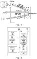
- FIG. 2 illustrates a block diagram of a node for wireless communication, in accordance with various aspects of the present application.
- a node 200 may include a transceiver 220, a processor 228, a memory 234, one or more presentation components 238, and at least one antenna 236.
- the node 200 may also include an RF (radio frequency) spectrum band module, a base station communications module, a network communications module, and a system communications management module, Input/Output (I/O) ports, I/O components, and power supply (not explicitly shown in FIG. 2 ).
- Each of these components may be in communication with each other, directly or indirectly, over one or more buses 240.
- the node 200 may be a UE or a base station that performs various functions described in the disclosure.
- the transceiver 220 having a transmitter 222 (e.g., transmitting/transmission circuitry) and a receiver 224 (e.g., receiving/reception circuitry) may be configured to transmit and/or receive time and/or frequency resource partitioning information.
- the transceiver 220 may be configured to transmit in different types of subframes and slots including, but not limited to, usable, non-usable and flexibly usable subframes and slot formats.
- the transceiver 220 may be configured to receive data and control channels.
- the node 200 may include a variety of computer-readable media.
- Computer-readable media can be any available media that can be accessed by the node 200 and include both volatile and non-volatile media, removable and non-removable media.
- Computer-readable media may include computer storage media and communication media.
- Computer storage media includes both volatile and non-volatile, removable and non-removable media implemented in any method or technology for storage of information such as computer-readable instructions.
- Computer storage media includes RAM, ROM, EEPROM, flash memory or other memory technology, CD-ROM, Digital Versatile Disks (DVD) or other optical disk storage, magnetic cassettes, magnetic tape, magnetic disk storage or other magnetic storage devices.
- Computer storage media does not include a propagated data signal.
- Communication media typically embodies computer-readable instructions, data structures, program modules or other data in a modulated data signal such as a carrier wave or other transport mechanism and includes any information delivery media.
- modulated data signal means a signal that has one or more of its characteristics set or changed in such a manner as to encode information in the signal.
- communication media includes wired media such as a wired network or direct-wired connection, and wireless media such as acoustic, RF, infrared and other wireless media. Combinations of any of the above should also be included within the scope of computer-readable media.
- the memory 234 may include computer-storage media in the form of volatile and/or non-volatile memory.
- the memory 234 may be removable, non-removable, or a combination thereof.
- Exemplary memory includes solid-state memory, hard drives, optical-disc drives, etc.
- the memory 234 may store computer-readable, computer-executable instructions 232 (e.g., software codes) that are configured to, when executed, cause the processor 228 to perform various functions described in the disclosure.
- the instructions 232 may not be directly executable by the processor 228 but be configured to cause the node 200 (e.g., when compiled and executed) to perform various functions described in the disclosure.
- the processor 228 may include an intelligent hardware device, e.g., a Central Processing Unit (CPU), a microcontroller, an ASIC, etc.
- the processor 228 may include memory.
- the processor 228 may process the data 230 and the instructions 232 received from the memory 234, and information through the transceiver 220, the base band communications module, and/or the network communications module.
- the processor 228 may also process information to be sent to the transceiver 220 for transmission through the antenna 236, to the network communications module for transmission to a core network.
- One or more presentation components 238 presents data indications to a person or other device.
- Exemplary presentation components 238 include a display device, speaker, printing component, vibrating component, etc.
- the UE e.g., the node 200 in FIG. 2
- the UE can be configured to perform DRX operations, and the basic idea of the DRX operation is introduced below.
- the NR support DRX mechanism and the DRX was introduced to control PDCCH monitoring for particular type(s) of RNTI.
- UE periodically monitor PDCCH according to the gNB's configuration and the realistic traffic pattern. That is, UE alternatively monitor PDCCH in some preconfigured Active Time even though there is no data transmission. However, if data transmission occurred during Active Time, the UE may extend its stay in Active for finishing the possible transmission.
- UE monitors PDCCH for possible data transmission/reception indication.
- UE's MAC (Medium Access Control) entity may be configured by RRC with a DRX functionality that controls the UE's PDCCH monitoring activity for particular type of RNTI. That is, in RRC_CONNECTED, if DRX is configured, the MAC entity is allowed to monitor the PDCCH for particular type of RNTI discontinuously follow the DRX operation.
- RRC controls DRX operation by configuring following parameters and timers: drx-LongCycle, drx-ShortCycle, drx-ShortCycleTimer, drx-StartOffset, drx-SlotOffset, drx-onDurationTimer, drx-InactivityTimer, drx-HARQ-RTT-TimerDL, drx-RetransmissionTimerDL.
- FIG. 3 shows protocol stacks of UE according to an embodiment of the disclosure.
- MBS radio bearer MBS radio bearer
- the PDCP (Packet Data Convergence Protocol) entity can determine to use at least one of PTM and PTP. In one embodiment, if the PDCP entity determines to use PTM, the RLC (radio link control) entity and the MAC entity can receive the MBS service based on the G-RNTI and/or C-RNTI. In one embodiment, if the PDCP entity determines to use PTP, the RLC entity and the MAC entity can receive the MBS service based on the C-RNTI.
- the gNB may have flexibility on controlling the DRX operation independently among the multiple of transmission schemes. Furthermore, the gNB may also have flexibility on controlling the DRX operation independently among PDDCH associated with MBS and PDCCH which is not associated with MBS.
- gNB configuring DRX and how the UE behave once the UE is configured with a first PDCCH (e.g., CORESET/search space) associated with MBS and a second PDCCH (e.g., CORESET/search space) which is not associated with MBS.
- a first PDCCH e.g., CORESET/search space
- a second PDCCH e.g., CORESET/search space
- UE's behavior on PDCCH monitoring on the first and the second PDCCH are centralized control by a single DRX configuration.
- UE's behavior on PDCCH monitoring on the first and the second PDCCH are centralized control by two individual DRX configurations.
- the DRX related parameters and timer such as drx-LongCycle, drx-ShortCycle, drx-ShortCycleTimer, drx-StartOffset, drx-SlotOffset, drx-onDurationTimer, drx-InactivityTimer, drx-HARQ-RTT-TimerDL and drx-RetransmissionTimerDL were configured for different purposes.
- drx-LongCycle, drx-ShortCycle, drx-ShortCycleTimer, drx-StartOffset and drx-SlotOffset are configured for controlling cycle of active time.
- the drx-onDurationTimer and drx-InactivityTimer controlling the length of the active time.
- the drx-HARQ-RTT-TimerDL and drx-RetransmissionTimerDL controls the monitoring of scheduling for data retransmission.
- the gNB may configure these parameters and timers of different purpose as centralized operation or distributed operation individually.
- the UE may receive only one set of drx-LongCycle, drx-ShortCycle, drx-ShortCycleTimer, drx-StartOffset and drx-SlotOffset which were indicated by the gNB to share among MRB and non-MRB.
- the UE may receive only two sets of drx-onDurationTimer and drx-InactivityTimer, each are indicated by the gNB to applied for one of MRB and non-MRB.
- one set of the two sets of drx-onDurationTimer and drx-InactivityTimer is for MRB
- another set of the two sets of drx-onDurationTimer and drx-InactivityTimer is for non-MRB.
- a non-MRB may be referred to as a Data Radio Bearer (DRB).
- DRB Data Radio Bearer
- Table 1 Centralized DRX Distributed DRX Case I N/A • drx-LongCycle • drx-ShortCycle • drx-ShortCycleTimer • drx-StartOffset • drx-SlotOffset • drx-onDurationTimer • drx-InactivityTimer • drx-HARQ-RTT-TimerDL • drx-RetransmissionTimerDL Case II • drx-LongCycle • drx-onDurationTimer • drx-ShortCycle • drx-InactivityTimer • drx-ShortCycleTimer • drx-HARQ-RTT-TimerDL • drx-
- the UE may monitor PDCCH for C-RNTI.
- the UE may monitor PDCCH for G-RNTI.
- the gNB may apply C-RNTI to schedule data reception for non-MBS (or PTP transmission via MBS) and may apply G-RNTI to schedule data reception for MBS (e.g., PTM transmission via MBS).
- the UE may maintain/configure two drx-InactivityTimer (or any other DRX timer), one for non-MBS and the other for MBS.
- the drx-InactivityTimer for non-MBS may be referred to as a first drx-InactivityTimer
- the drx-InactivityTimer for MBS may be referred to as a second drx-InactivityTimer, but the disclosure is not limited thereto.
- the DRX timers for non-MBS or PTP transmission scheme and the DRX timers for MBS (or PTM transmission scheme) may be configured explicitly by the network.
- the network may configure all the DRX timers for non-MBS and/or PTP transmission scheme of a specific MBS (e.g., including the first drx-InactivityTimer ) in a first IE (e.g., DRX-Config IE).
- the network may configure all the DRX timers for a specific MBS and/or PTM transmission scheme of a specific MBS (e.g., including the second drx-InactivityTimer ) in a second IE (e.g., DRX-Config-MBS IE).
- the second IE (e.g., DRX-Config-MBS IE) may correspond to the specific MBS.
- all the DRX timers in the second IE may correspond to the (G-RNTI of the) specific MBS.
- all the DRX timers configured in the second IE may control the UE behaviour on PDCCH monitoring for the G-RNTI that corresponds to the specific MBS (e.g., for monitoring via a PTM transmission scheme I of the specific MBS).
- the UE may monitor on PDCCH for the G-RNTI that corresponds to the specific MBS.
- all the DRX timers configured in the first IE may control the UE behaviour on PDCCH monitoring for a C-RNTI (e.g., for monitoring via a PTP transmission scheme).
- the UE may (re)start the first drx-InactivityTimer of non-MBS (or any other DRX timer configured for non-MBS): (a) the transmission scheme is switched from PTM transmission scheme to PTP transmission scheme; (b) the transmission scheme is switched from PTM transmission scheme I (G-RNTI) to PTP transmission scheme; (c) the transmission scheme is switched from PTM transmission scheme II (C-RNTI) to PTP transmission scheme; (d) UE receives any indicator indicating any of situations of (a), (b) and (c) as above; (e) the UE transmits a HARQ feedback in response to a data reception scheduled by the gNB through G-RNTI (e.g., PTM transmission scheme I); (f) the UE transmits a HARQ feedback in response to a data reception scheduled by the gNB through G-RNTI (e.g., PTM transmission scheme I), and the HARQ feedback indicating NACK
- a DCI is received, and the DCI with Cyclic Redundancy Check (CRC) bits scrambled by C-RNTI schedule group common PDSCH reception;
- CRC Cyclic Redundancy Check
- UE receives a DCI with CRC bits scrambled by G-RNTI;
- UE receives a DCI with CRC bits scrambled by G-RNTI and the DCI also indicates the scheduled PDSCH reception is new transmission.
- the indicator may be referred to as a RRC signaling to indicate the switching from PTM transmission scheme to PTP transmission scheme.
- the RRC signaling may indicate the release of a RLC entity that corresponds to the PTM leg for performing PTM transmission (scheme I/scheme II).
- the RRC signaling may also indicate the addition of a RLC entity that corresponds to the PTP leg for perform PTP transmission.
- the indicator may be referred to as a DCI or a MAC CE to indicate the switching from PTM transmission scheme to PTP transmission scheme.
- the DCI or the MAC CE may indicate the deactivation of G-RNTI monitoring for the corresponding PTM transmission.
- the UE may stop monitoring on PDCCH for DCI associated with G-RNTI for PTM transmission upon receiving the DCI or the MAC CE which indicates the switching from PTM transmission scheme to PTP transmission scheme.
- a DCI associated with G-RNTI may be transmitted on PDCCH for scheduling of a group-common PDSCH in the DL.
- the group-common PDSCH (scrambled by the G-RNTI) may include MBS data packet.
- This transmission scheme may also be referred to as PTM transmission scheme I in the present disclosure.
- a DCI associated with C-RNTI may be transmitted on PDCCH for scheduling of a group-common PDSCH in the DL.
- the group-common PDSCH (scrambled by the G-RNTI) may include MBS data packet.
- This transmission scheme may also be referred to as PTM transmission scheme II in the present disclosure.
- the UE may send a HARQ feedback to the gNB.
- the HARQ feedback may indicate either Acknowledgement (ACK) or Negative-Acknowledgement (NACK) for the corresponding data, depending on whether or not the data is successfully received.
- the HARQ feedback may correspond to the same HARQ process as the data scheduled by the gNB.
- the UE may send an ACK as a HARQ feedback to the network if the data is successfully received by the UE.
- the UE may send a NACK as a HARQ feedback to the network if the data is not successfully received by the UE.
- the HARQ feedback may also associate with the first HARQ process ID.
- the UE may (re)start the second drx-InactivityTimer of MBS (or any other DRX timer configured for MBS): (a) the transmission scheme is switched from PTP transmission scheme to PTM transmission scheme I or II; (b) the UE receives any indicator indicating the situation (a) as above; (c) the UE transmits a HARQ feedback in response to a data reception scheduled by the gNB through G-RNTI (e.g., PTM transmission scheme I); (d) the UE transmits a HARQ feedback in response to a data reception scheduled by the gNB through G-RNTI (e.g., PTM transmission scheme I), and the HARQ feedback indicating NACK; (e) UE is scheduled by gNB with a data reception through PTM transmission scheme I, i.e., a DCI is received, and the DCI with CRC bits scrambled by G-RNTI schedule group common PDSCH reception
- the indicator may be referred to as a RRC signaling to indicate the switching from PTP transmission scheme to PTM transmission scheme.
- the RRC signaling may indicate the release of a RLC entity that corresponds to the PTP leg for performing PTP transmission.
- the RRC signaling may also indicate the addition of a RLC entity that corresponds to the PTM leg for perform PTM transmission (scheme I/scheme II).
- the indicator may be referred to as a DCI or a MAC CE to indicate the switching from PTP transmission scheme to PTM transmission scheme.
- the DCI or the MAC CE may indicate the activation of G-RNTI monitoring for the corresponding PTM transmission.
- the UE may start monitoring on PDCCH for DCI associated with G-RNTI for PTM transmission upon receiving the DCI or the MAC CE which indicates the switching from PTP transmission scheme to PTM transmission scheme.
- the UE may maintain a drx-InactivityTimer (or any other DRX timer) for both non-MBS and MBS.
- the drx-InactivityTimer for both non-MBS and MBS can be referred to as a third drx-InactivityTimer, but the disclosure is not limited thereto.
- the UE may (re)start the third drx-InactivityTimer (or any other DRX timer configured for both non-MBS and MBS): (a) the transmission scheme is switched from PTM transmission scheme to PTP transmission scheme; (b) the transmission scheme is switched from PTM transmission scheme I to PTP transmission scheme; (c) the transmission scheme is switched from PTM transmission scheme II to PTP transmission scheme; (d) the transmission scheme is switched from PTP transmission scheme to PTM transmission scheme I or II; (e) UE receives any indicator indicating any of situation of (a), (b), (c) and (d) as above; (f) UE is scheduled by gNB with a data reception through PTM transmission scheme I.
- a DCI is received, and the DCI with CRC bits scrambled by G-RNTI schedule group common PDSCH reception;
- UE receives a DCI with CRC bits scrambled by G-RNTI;
- UE receives a DCI with CRC bits scrambled by G-RNTI and the DCI also indicates the scheduled PDSCH reception is new transmission.
- the distributed DRX may be interpreted (implemented) as the UE is configured by the gNB with two sets of DRX related parameters and timers, wherein the two sets of DRX related parameter can be applied for PTP transmission scheme and PTM transmission scheme (I or II), respectively.
- the Cases I, II and III mentioned above may also be interpreted as the DRX related parameters and timers are configured individually for PTP transmission scheme and PTM transmission scheme (I or II).
- definition of the cases listed in the Table 1 may be interpreted as below.
- Case I All the parameters and timers are configured by the gNB to operate as distributed. That is, the UE receives two sets of: drx-LongCycle, drx-ShortCycle, drx-ShortCycleTimer, drx-StartOffset, drx-SlotOffset, drx-onDurationTimer, drx-InactivityTimer, drx-HARQ-RTT-TimerDL and drx-RetransmissionTimerDL.
- One set of the two sets is for an PTP transmission scheme
- another set of the two sets is for PTM transmission scheme (I or II)
- the parameters and timers mention above are merely exemplary.
- the gNB may not configure all the parameters and timers (i.e., few of them may be optionally configured), the Case I may be implemented/interpreted as only part of parameters and timers are configured. In addition, the part of parameters and timers are all individually applied for PTP transmission scheme and PTM transmission scheme (I or II) (distributed DRX).
- Case II UE is configured with one set of the timers and parameters for controlling cycle of active time and is also configured with two sets of the timers and parameters for controlling the length of the active time and for controlling the monitoring of scheduling for data retransmission. That is, the set of timers and parameters for controlling cycle of active time are shared among PTP transmission scheme and PTM transmission scheme (I or II). In addition, each of the two sets of the timers and parameters for controlling the length of the active time and for controlling the monitoring of scheduling for data retransmission is individually applied for PTP transmission scheme and PTM transmission scheme (I or II) (distributed DRX).
- Case III UE is configured with one set of the timers and parameters for controlling cycle of active time and for controlling the length of the active time.
- the UE is configured with two sets of the timers and parameters and for controlling the monitoring of scheduling for data retransmission. That is, the set of timers and parameters for controlling cycle of active time and controlling the length of the active time are shared among PTP transmission scheme and PTM transmission scheme (I or II) (centralized DRX).
- each of the two sets of the timers and parameters for controlling the monitoring of scheduling for data retransmission is individually applied for PTP transmission scheme and PTM transmission scheme (I or II) (distributed DRX).
- the UE may monitor PDCCH for C-RNTI.
- the UE may monitor PDCCH for G-RNTI.
- the UE may maintain two drx-InactivityTimer, and each for PTP transmission scheme and PTM transmission scheme (I or II).
- the drx-InactivityTimer for PTP transmission scheme may be referred to as a fourth drx-InactivityTimer
- the drx-InactivityTimer for PTM transmission scheme (I or II) may be referred to as a fifth drx-InactivityTimer, but the disclosure is not limited thereto.
- the UE may (re)start the fourth drx-InactivityTimer (or any other configured DRX timer) of PTP transmission scheme: (a) the transmission scheme is switched from PTM transmission scheme to PTP transmission scheme; (b) the transmission scheme is switched from PTM transmission scheme I to PTP transmission scheme; (c) the transmission scheme is switched from PTM transmission scheme II to PTP transmission scheme; (d) UE receives any indicator indicating any of situation of (a), (b) and (c) as above; (e) UE transmits a HARQ feedback in response to a data reception scheduled by the gNB through G-RNTI (e.g., PTM transmission scheme I); (f) UE transmits a HARQ feedback in response to a data reception scheduled by the gNB through G-RNTI (e.g., PTM transmission scheme I), and the HARQ feedback indicating NACK; (g) UE is scheduled by gNB with a data reception through P
- a DCI is received, and the DCI with CRC bits scrambled by C-RNTI schedule group common PDSCH reception;
- UE receives a DCI with CRC bits scrambled by G-RNTI;
- UE receives a DCI with CRC bits scrambled by G-RNTI and the DCI also indicates the scheduled PDSCH reception is new transmission.
- the UE may (re)start the fifth drx-InactivityTimer (or any other configured DRX timer) of PTM transmission scheme (I or II): (a) The transmission scheme is switched from PTP transmission scheme to PTM transmission scheme I or II; (b) UE receives any indicator indicating the situation a as above; (c) UE transmits a HARQ feedback in response to a data reception scheduled by the gNB through G-RNTI (e.g., PTM transmission scheme I); (d) UE transmits a HARQ feedback in response to a data reception scheduled by the gNB through G-RNTI (e.g., PTM transmission scheme I), and the HARQ feedback indicating NACK; (e) UE is scheduled by gNB with a data reception through PTM transmission scheme I, i.e., a DCI is received, and the DCI with CRC bits scrambled by G-RNTI schedule group common PDSCH reception
- the UE may maintain a drx-InactivityTimer shared among PTP transmission scheme and PTM transmission scheme (I or II).
- the drx-InactivityTimer shared among PTP transmission scheme and PTM transmission scheme (I or II) can be referred to as a sixth drx-InactivityTimer, but the disclosure is not limited thereto.
- the UE may (re)start the sixth drx-InactivityTimer (or any other configured DRX timer that is shared among PTP transmission scheme and PTM transmission scheme I or II): (a) the transmission scheme is switched from PTM transmission scheme to PTP transmission scheme; (b) the transmission scheme is switched from PTM transmission scheme I to PTP transmission scheme; (c) the transmission scheme is switched from PTM transmission scheme II to PTP transmission scheme; (d) the transmission scheme is switched from PTP transmission scheme to PTM transmission scheme I or II; (e) UE receives any indicator indicating any of situation of a, b, c and d as above; (f) UE is scheduled by gNB with a data reception through PTM transmission scheme I.
- the sixth drx-InactivityTimer or any other configured DRX timer that is shared among PTP transmission scheme and PTM transmission scheme I or II
- a DCI is received, and the DCI with CRC bits scrambled by G-RNTI schedule group common PDSCH reception;
- UE receives a DCI with CRC bits scrambled by G-RNTI;
- UE receives a DCI with CRC bits scrambled by G-RNTI and the DCI also indicates the scheduled PDSCH reception is new transmission.
- the distributed DRX may be interpreted (implemented) as the UE is configured by the gNB with two sets of DRX related parameters and timers. In one embodiment, one of the two sets is applied for traffic scheduled by C-RNTI, and another set of the two sets is applied for traffic associated with PTM transmission scheme I.
- the Case I, II and III mentioned above may also be interpreted as the DRX related parameters and timers are configured individually for traffic scheduled by C-RNTI and traffic associated with PTM transmission scheme I.
- the UE may monitor PDCCH for C-RNTI.
- the UE may monitor PDCCH for G-RNTI.
- the UE may maintain two drx-InactivityTimer, and each for traffic scheduled by C-RNTI and traffic associated with PTM transmission scheme (I or II).
- the drx-InactivityTimer for traffic scheduled by C-RNTI may be referred to as a seventh drx-InactivityTimer
- the drx-InactivityTimer for traffic associated with PTM transmission scheme (I or II) may be referred to as an eighth drx-InactivityTimer, but the disclosure is not limited thereto.
- the UE may (re)start the seventh drx-InactivityTimer (or any other configured DRX timer) for traffic scheduled by C-RNTI: (a) the transmission scheme is switched from PTM transmission scheme to PTP transmission scheme; (b) the transmission scheme is switched from PTM transmission scheme I to PTP transmission scheme; (c) the transmission scheme is switched from PTM transmission scheme II to PTP transmission scheme; (d) UE receives any indicator indicating any of situation of (a), (b) and (c) as above; (e) UE transmits a HARQ feedback in response to a data reception scheduled by the gNB through G-RNTI (e.g., PTM transmission scheme I); (f) UE transmits a HARQ feedback in response to a data reception scheduled by the gNB through G-RNTI (e.g., PTM transmission scheme I), and the HARQ feedback indicating NACK; (g) UE is scheduled by gNB with a data
- the UE may (re)start the eighth drx-InactivityTimer (or any other configured DRX timer) of traffic associated with PTM transmission scheme (I or II): (a) The transmission scheme is switched from PTP transmission scheme to PTM transmission scheme I or II; (b) UE receives any indicator indicating the situation a as above; (c) UE transmits a HARQ feedback in response to a data reception scheduled by the gNB through G-RNTI (e.g., PTM transmission scheme I); (d) UE transmits a HARQ feedback in response to a data reception scheduled by the gNB through G-RNTI (e.g., PTM transmission scheme I), and the HARQ feedback indicating NACK; (e) UE is scheduled by gNB with a data reception through PTM transmission scheme I, i.e., a DCI is received, and the DCI with CRC bits scrambled by G-RNTI schedule group common
- the UE may maintain a drx-InactivityTimer shared among traffic scheduled by C-RNTI and traffic associated with PTM transmission scheme (I or II).
- the drx-InactivityTimer shared among traffic scheduled by C-RNTI and traffic associated with PTM transmission scheme (I or II) can be referred to as a ninth drx-InactivityTimer, but the disclosure is not limited thereto.
- the UE may (re)start the ninth drx-InactivityTimer (or any other configured DRX timer): (a) the transmission scheme is switched from PTM transmission scheme to PTP transmission scheme; (b) the transmission scheme is switched from PTM transmission scheme I to PTP transmission scheme; (c) the transmission scheme is switched from PTM transmission scheme II to PTP transmission scheme; (d) the transmission scheme is switched from PTP transmission scheme to PTM transmission scheme I or II; (e) UE receives any indicator indicating any of situation of a, b, c and d as above; (f) UE is scheduled by gNB with a data reception through PTM transmission scheme I, i.e., a DCI is received, and the DCI with CRC bits scrambled by G-RNTI schedule group common PDSCH reception; (g) UE receives a DCI with CRC bits scrambled by G-RNTI; (h) UE receives a DCI
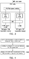
- FIG. 4 shows a flow chart of the method for configuring a DRX setting according to an embodiment of the disclosure.
- the method of this embodiment may be executed by the UE (e.g., the node 200 in FIG. 2 ), and the details of each step in FIG. 4 will be described below with the components shown in FIG. 2 .
- the processor 228 controls the transceiver 220 to receive at least one configuration from a network node.
- the network node can be the serving base station, the serving cell of the UE, and/or gNB.
- the configuration is used for receiving an MBS.
- the configuration includes a first RNTI and a plurality of first DRX parameters used for monitoring a PDCCH based on the first RNTI, and the UE receives the MBS from the network node via at least one of a PTP transmission scheme and a PTM transmission scheme.
- step S420 the processor 228 controls the transceiver 220 to receive an indication from the network node.
- step S430 the processor 228 starts a first DRX timer associated with the first DRX parameters in response to the indication.
- the first RNTI is one of a group-RNTI (G-RNTI) and a UE-specific RNTI (e.g., a C-RNTI).
- G-RNTI group-RNTI
- C-RNTI UE-specific RNTI
- the configuration from the network node further includes a plurality of second DRX parameters, wherein the second DRX parameters are used for monitoring the PDCCH based on a second RNTI.
- the processor 228 further starts a second DRX timer associated with the second DRX parameters in response to the indication.
- the second RNTI is another of the G-RNTI and the UE-specific RNTI.
- the first RNTI and the second RNTI would be assumed to be the G-RNTI and the UE-specific RNTI, respectively.
- the indication can correspond to one or a combination of the situations mentioned in the first/second/third embodiments.
- the indication can indicate that a transmission using at least one of the PTM transmission scheme and the PTP transmission scheme begins.
- the processor 128 accordingly starts at least one of the first DRX timer and the second DRX timer in response to the indication.
- the indication can indicate that a transmission using at least one of the PTM transmission scheme and the PTP transmission scheme finishes.
- the processor 128 accordingly starts at least one of the first DRX timer and the second DRX timer in response to the indication.
- the indication further indicates that the transmission scheme is switched from one of the PTM transmission scheme and the PTP transmission scheme to another of the PTM transmission scheme and the PTP transmission scheme.
- the processor 128 accordingly starts at least one of the first DRX timer and the second DRX timer in response to the indication.
- the first DRX parameters can be regarded as a first set of the two sets of DRX related parameters and timers configured by the gNB
- the second DRX parameters can be regarded as a second set of the two sets of DRX related parameters and timers configured by the gNB
- the first DRX timer associated with the first DRX parameters can be the timers for PTM transmission scheme (I or II), which includes at least one of a drx-ShortCycleTimer, drx-onDurationTimer, drx-InactivityTimer (e.g., the fifth drx-InactivityTimer mentioned in the above), drx-HARQ-RTT-TimerDL, drx-RetransmissionTimerDL particular for PTM transmission scheme (I or II).
- PTM transmission scheme I or II
- drx-ShortCycleTimer drx-onDurationTimer
- drx-InactivityTimer e.g., the fifth drx-InactivityTimer mentioned in the above
- drx-HARQ-RTT-TimerDL e.g., the fifth drx-InactivityTimer mentioned in the above
- drx-HARQ-RTT-TimerDL e.g.
- the UE may (re)start one or more of the timers for the PTM transmission scheme (I or II) as the first DRX timer: (a) The transmission scheme is switched from PTP transmission scheme to PTM transmission scheme I or II; (b) UE receives any indicator indicating the situation (a) as above; (c) UE transmits a HARQ feedback in response to a data reception scheduled by the gNB through G-RNTI (e.g., PTM transmission scheme I); (d) UE transmits a HARQ feedback in response to a data reception scheduled by the gNB through G-RNTI (e.g., PTM transmission scheme I), and the HARQ feedback indicating NACK; (e) UE is scheduled by gNB with a data reception through PTM transmission scheme I, i.e., a DCI is received, and the DCI with CRC bits scrambled by G-RNTI schedule group common PDSCH reception
- the second DRX timer associated with the second DRX parameters can be the timers for PTP transmission scheme, which includes at least one of a drx-ShortCycleTimer, drx-onDurationTimer, drx-InactivityTimer (e.g., the fourth drx-InactivityTimer mentioned in the above), drx-HARQ-RTT-TimerDL, drx-RetransmissionTimerDL particular for PTP transmission scheme.
- a drx-ShortCycleTimer drx-onDurationTimer
- drx-InactivityTimer e.g., the fourth drx-InactivityTimer mentioned in the above
- drx-HARQ-RTT-TimerDL e.g., the fourth drx-InactivityTimer mentioned in the above
- drx-HARQ-RTT-TimerDL e.g., the fourth drx-InactivityTimer mentioned in the
- the UE may (re)start one or more of the timers for the PTP transmission scheme as the second DRX timer: (a) the transmission scheme is switched from PTM transmission scheme to PTP transmission scheme; (b) the transmission scheme is switched from PTM transmission scheme I to PTP transmission scheme; (c) the transmission scheme is switched from PTM transmission scheme II to PTP transmission scheme; (d) UE receives any indicator indicating any of situation of (a), (b) and (c) as above; (e) UE transmits a HARQ feedback in response to a data reception scheduled by the gNB through G-RNTI (e.g., PTM transmission scheme I); (f) UE transmits a HARQ feedback in response to a data reception scheduled by the gNB through G-RNTI (e.g., PTM transmission scheme I), and the HARQ feedback indicating NACK; (g) UE is scheduled by gNB with a data reception through PTM
- a DCI is received, and the DCI with CRC bits scrambled by C-RNTI schedule group common PDSCH reception;
- UE receives a DCI with CRC bits scrambled by G-RNTI;
- UE receives a DCI with CRC bits scrambled by G-RNTI and the DCI also indicates the scheduled PDSCH reception is new transmission.
- FIG. 4 details of FIG. 4 can be also referred to descriptions related to one or more of the above embodiments, in particular, the second embodiment, which would not be repeated herein.
- the UE when the UE is configured, by the network node, with the first RNTI (e.g., a G-RNTI) and the first DRX parameters, the UE can start the first DRX timer associated with the first DRX parameters in response to various indications.
- the UE when the UE is further configured, by the network node, with the second RNTI (e.g., a C-RNTI) and the second DRX parameters, the UE can further start the second DRX timer associated with the second DRX parameters in response to the indications.
- the first RNTI e.g., a G-RNTI
- the UE when the UE is further configured, by the network node, with the second RNTI (e.g., a C-RNTI) and the second DRX parameters, the UE can further start the second DRX timer associated with the second DRX parameters in response to the indications.
- the second RNTI e.g., a C-
- the first DRX parameters can be considered as being configured for one of PTP transmission scheme and PTM transmission scheme
- the second DRX parameters can be considered as being configured for another of PTP transmission scheme and PTM transmission scheme.
- the UE can be configured with two sets of DRX parameters, in which one set is used for PTP transmission scheme, and another set is for PTM transmission scheme.
Landscapes
- Engineering & Computer Science (AREA)
- Signal Processing (AREA)
- Computer Networks & Wireless Communication (AREA)
- Multimedia (AREA)
- Mobile Radio Communication Systems (AREA)
Applications Claiming Priority (1)
| Application Number | Priority Date | Filing Date | Title |
|---|---|---|---|
| US202163138135P | 2021-01-15 | 2021-01-15 |
Publications (1)
| Publication Number | Publication Date |
|---|---|
| EP4030867A1 true EP4030867A1 (de) | 2022-07-20 |
Family
ID=79601553
Family Applications (1)
| Application Number | Title | Priority Date | Filing Date |
|---|---|---|---|
| EP22151464.9A Withdrawn EP4030867A1 (de) | 2021-01-15 | 2022-01-13 | Verfahren zur konfiguration einer diskontinuierlichen empfangseinstellung und benutzergerät |
Country Status (3)
| Country | Link |
|---|---|
| US (1) | US20220232661A1 (de) |
| EP (1) | EP4030867A1 (de) |
| CN (1) | CN114765905B (de) |
Cited By (1)
| Publication number | Priority date | Publication date | Assignee | Title |
|---|---|---|---|---|
| EP4154647A4 (de) * | 2021-08-05 | 2023-10-11 | Apple Inc. | Übertragung mit diskontinuierlichem empfang |
Families Citing this family (5)
| Publication number | Priority date | Publication date | Assignee | Title |
|---|---|---|---|---|
| CN115022815B (zh) * | 2021-03-05 | 2023-07-21 | 维沃移动通信有限公司 | 多播业务的接收方法、装置及电子设备 |
| CN115706931B (zh) * | 2021-08-06 | 2025-10-28 | 华为技术有限公司 | 通信方法及装置 |
| US11646829B2 (en) * | 2021-09-14 | 2023-05-09 | Asustek Computer Inc. | Method and apparatus for handling discontinuous reception (DRX) timer for data reception of unicast and multicast in a wireless communication system |
| WO2024032222A1 (zh) * | 2022-08-09 | 2024-02-15 | 华为技术有限公司 | 一种通信方法及装置 |
| US20260106663A1 (en) * | 2022-11-04 | 2026-04-16 | Apple Inc. | Systems, methods, and devices for control information for network-control repeater (ncr) |
Family Cites Families (12)
| Publication number | Priority date | Publication date | Assignee | Title |
|---|---|---|---|---|
| JP4402594B2 (ja) * | 2002-08-01 | 2010-01-20 | インターデイジタル テクノロジー コーポレーション | 共通ページングチャネルにおけるページング時機を調整する方法 |
| AU2008202179B8 (en) * | 2004-01-07 | 2010-07-22 | Samsung Electronics Co., Ltd. | Method for transmitting messages related to a broadcast or multicast service in a cellular communications system |
| US9473906B2 (en) * | 2013-03-22 | 2016-10-18 | Mediatek Inc. | Idle mode reception for group communication over LTE eMBMS |
| CN107852627A (zh) * | 2015-08-11 | 2018-03-27 | Lg电子株式会社 | 用于终端执行关于scptm的pdcch监测的方法和装置 |
| US10383087B2 (en) * | 2016-05-04 | 2019-08-13 | Lg Electronics Inc. | Method and apparatus for paging terminal in a light connection state in wireless communication system |
| JP6741969B2 (ja) * | 2016-09-30 | 2020-08-19 | 京セラ株式会社 | 移動通信システム |
| ES3059985T3 (en) * | 2020-03-24 | 2026-03-24 | Zte Corp | Dynamically changing multicast/broadcast service delivery |
| US20230110505A1 (en) * | 2020-05-27 | 2023-04-13 | Mediatek Singapore Pte. Ltd. | Methods and apparatus of reliable multicast transmission |
| WO2022000180A1 (en) * | 2020-06-29 | 2022-01-06 | Mediatek Singapore Pte. Ltd. | Methods and apparatus of reliable multicast transmission with uplink feedback |
| US20230171566A1 (en) * | 2020-07-21 | 2023-06-01 | Mediatek Singapore Pte. Ltd. | Multicast broadcast service reception with duplicated data packets |
| TWI792614B (zh) * | 2020-10-19 | 2023-02-11 | 新加坡商聯發科技(新加坡)私人有限公司 | 用於多播廣播服務的方法和使用者設備 |
| CN116998219A (zh) * | 2020-11-09 | 2023-11-03 | 欧芬诺有限责任公司 | 多播和广播服务的不连续接收操作 |
-
2022
- 2022-01-03 US US17/567,158 patent/US20220232661A1/en not_active Abandoned
- 2022-01-13 EP EP22151464.9A patent/EP4030867A1/de not_active Withdrawn
- 2022-01-14 CN CN202210043318.2A patent/CN114765905B/zh active Active
Non-Patent Citations (2)
| Title |
|---|
| 3GPP TS 38.331 |
| INTEL CORPORATION: "Dynamic switch between PTM and PTP for service continuity", vol. RAN WG2, no. Electronic meeting; 20201102 - 20201113, 23 October 2020 (2020-10-23), XP051942037, Retrieved from the Internet <URL:https://ftp.3gpp.org/tsg_ran/WG2_RL2/TSGR2_112-e/Docs/R2-2008989.zip R2-2008989.docx> [retrieved on 20201023] * |
Cited By (3)
| Publication number | Priority date | Publication date | Assignee | Title |
|---|---|---|---|---|
| EP4154647A4 (de) * | 2021-08-05 | 2023-10-11 | Apple Inc. | Übertragung mit diskontinuierlichem empfang |
| US20240023197A1 (en) * | 2021-08-05 | 2024-01-18 | Apple Inc. | Discontinuous Reception Transmission |
| US12452950B2 (en) | 2021-08-05 | 2025-10-21 | Apple Inc. | Discontinuous reception transmission |
Also Published As
| Publication number | Publication date |
|---|---|
| CN114765905B (zh) | 2025-10-10 |
| US20220232661A1 (en) | 2022-07-21 |
| CN114765905A (zh) | 2022-07-19 |
Similar Documents
| Publication | Publication Date | Title |
|---|---|---|
| US12200739B2 (en) | Method and user equipment for multicast/broadcast service data reception | |
| EP4118786B1 (de) | Benutzergerät und verfahren für multicast-/broadcast-dienst | |
| EP4030867A1 (de) | Verfahren zur konfiguration einer diskontinuierlichen empfangseinstellung und benutzergerät | |
| US12219435B2 (en) | Method and user equipment for management of MBS data reception | |
| US12256372B2 (en) | Method and device for multicast broadcast service acquisition | |
| CN103716142B (zh) | 由基站实施的用于多载波操作的方法以及该基站 | |
| US10045395B2 (en) | Base station, processor, and user terminal for setting a configuration to the user terminal for discontinuously monitoring a physical downlink control channel (PDCCH) on which a control signal is transmitted by the base station | |
| US11646829B2 (en) | Method and apparatus for handling discontinuous reception (DRX) timer for data reception of unicast and multicast in a wireless communication system | |
| US20230209313A1 (en) | Wireless communication method and user equipment for ul feedback | |
| US10142977B2 (en) | Method for receiving downlink control channel in wireless communication system applying carrier aggregation technique, and apparatus therefor | |
| US11824662B2 (en) | Method and apparatus for discontinuous reception regarding PUCCH transmission in a wireless communication system | |
| US20220321280A1 (en) | Method of harq process for multicast broadcast service and user equipment using the same | |
| CN106134278B (zh) | 无线通信系统中发送和接收用于设备对设备通信的信号的方法及其装置 | |
| CN117320189A (zh) | 通信方法及装置 | |
| US11962420B1 (en) | Method and apparatus of handling discontinuous reception (DRX) timer for multicast data reception in a wireless communication system | |
| CN117596721A (zh) | 用于多播/广播服务相关操作的方法和设备 | |
| KR102538045B1 (ko) | 무선 통신 시스템에서 그룹 공통 전송을 위한 harq 기반 송수신 방법 및 장치 | |
| WO2022228562A1 (en) | Method and device for multicast broadcast service acquisition | |
| US12082292B2 (en) | Method and apparatus of handling discontinuous reception (DRX) command for MBS (multicast broadcast service) operation in a wireless communication system |
Legal Events
| Date | Code | Title | Description |
|---|---|---|---|
| PUAI | Public reference made under article 153(3) epc to a published international application that has entered the european phase |
Free format text: ORIGINAL CODE: 0009012 |
|
| STAA | Information on the status of an ep patent application or granted ep patent |
Free format text: STATUS: THE APPLICATION HAS BEEN PUBLISHED |
|
| AK | Designated contracting states |
Kind code of ref document: A1 Designated state(s): AL AT BE BG CH CY CZ DE DK EE ES FI FR GB GR HR HU IE IS IT LI LT LU LV MC MK MT NL NO PL PT RO RS SE SI SK SM TR |
|
| STAA | Information on the status of an ep patent application or granted ep patent |
Free format text: STATUS: THE APPLICATION IS DEEMED TO BE WITHDRAWN |
|
| 18D | Application deemed to be withdrawn |
Effective date: 20230121 |