EP4030782A1 - Air-pulse generating device and sound producing method thereof - Google Patents
Air-pulse generating device and sound producing method thereof Download PDFInfo
- Publication number
- EP4030782A1 EP4030782A1 EP22150681.9A EP22150681A EP4030782A1 EP 4030782 A1 EP4030782 A1 EP 4030782A1 EP 22150681 A EP22150681 A EP 22150681A EP 4030782 A1 EP4030782 A1 EP 4030782A1
- Authority
- EP
- European Patent Office
- Prior art keywords
- air
- membrane
- pulse generating
- generating device
- chamber
- Prior art date
- Legal status (The legal status is an assumption and is not a legal conclusion. Google has not performed a legal analysis and makes no representation as to the accuracy of the status listed.)
- Pending
Links
- 238000000034 method Methods 0.000 title claims description 14
- 239000012528 membrane Substances 0.000 claims abstract description 237
- 230000033001 locomotion Effects 0.000 claims abstract description 84
- 230000001360 synchronised effect Effects 0.000 claims abstract description 18
- 230000005236 sound signal Effects 0.000 claims description 7
- 238000006073 displacement reaction Methods 0.000 description 43
- 238000010586 diagram Methods 0.000 description 23
- 230000007704 transition Effects 0.000 description 18
- 230000006870 function Effects 0.000 description 14
- 230000005855 radiation Effects 0.000 description 8
- 230000008859 change Effects 0.000 description 6
- 230000008569 process Effects 0.000 description 6
- 238000006243 chemical reaction Methods 0.000 description 5
- 238000013461 design Methods 0.000 description 5
- 238000004519 manufacturing process Methods 0.000 description 5
- 230000003595 spectral effect Effects 0.000 description 5
- 230000000694 effects Effects 0.000 description 4
- 239000010408 film Substances 0.000 description 3
- 239000002245 particle Substances 0.000 description 3
- 239000000758 substrate Substances 0.000 description 3
- 238000002604 ultrasonography Methods 0.000 description 3
- 238000005452 bending Methods 0.000 description 2
- 230000006835 compression Effects 0.000 description 2
- 238000007906 compression Methods 0.000 description 2
- 230000017525 heat dissipation Effects 0.000 description 2
- 239000012212 insulator Substances 0.000 description 2
- 239000000463 material Substances 0.000 description 2
- 229910021420 polycrystalline silicon Inorganic materials 0.000 description 2
- 230000000644 propagated effect Effects 0.000 description 2
- 230000004044 response Effects 0.000 description 2
- 230000002123 temporal effect Effects 0.000 description 2
- RYGMFSIKBFXOCR-UHFFFAOYSA-N Copper Chemical compound [Cu] RYGMFSIKBFXOCR-UHFFFAOYSA-N 0.000 description 1
- 230000009471 action Effects 0.000 description 1
- 229910052782 aluminium Inorganic materials 0.000 description 1
- XAGFODPZIPBFFR-UHFFFAOYSA-N aluminium Chemical compound [Al] XAGFODPZIPBFFR-UHFFFAOYSA-N 0.000 description 1
- 238000003491 array Methods 0.000 description 1
- 230000008901 benefit Effects 0.000 description 1
- 230000033228 biological regulation Effects 0.000 description 1
- 239000004020 conductor Substances 0.000 description 1
- 229910052802 copper Inorganic materials 0.000 description 1
- 239000010949 copper Substances 0.000 description 1
- 230000001419 dependent effect Effects 0.000 description 1
- 238000001514 detection method Methods 0.000 description 1
- 238000011161 development Methods 0.000 description 1
- 230000018109 developmental process Effects 0.000 description 1
- 239000000428 dust Substances 0.000 description 1
- 238000005530 etching Methods 0.000 description 1
- 239000012530 fluid Substances 0.000 description 1
- 230000006872 improvement Effects 0.000 description 1
- 230000007774 longterm Effects 0.000 description 1
- 230000007246 mechanism Effects 0.000 description 1
- 229910052751 metal Inorganic materials 0.000 description 1
- 239000002184 metal Substances 0.000 description 1
- 230000037361 pathway Effects 0.000 description 1
- 238000000206 photolithography Methods 0.000 description 1
- 229920005591 polysilicon Polymers 0.000 description 1
- 238000012545 processing Methods 0.000 description 1
- 230000001902 propagating effect Effects 0.000 description 1
- 230000001681 protective effect Effects 0.000 description 1
- 229910052710 silicon Inorganic materials 0.000 description 1
- 239000010703 silicon Substances 0.000 description 1
- 239000007787 solid Substances 0.000 description 1
- 125000006850 spacer group Chemical group 0.000 description 1
- 239000010409 thin film Substances 0.000 description 1
- 238000012546 transfer Methods 0.000 description 1
- 235000012431 wafers Nutrition 0.000 description 1
Images


Classifications
-
- H—ELECTRICITY
- H04—ELECTRIC COMMUNICATION TECHNIQUE
- H04R—LOUDSPEAKERS, MICROPHONES, GRAMOPHONE PICK-UPS OR LIKE ACOUSTIC ELECTROMECHANICAL TRANSDUCERS; DEAF-AID SETS; PUBLIC ADDRESS SYSTEMS
- H04R7/00—Diaphragms for electromechanical transducers; Cones
- H04R7/02—Diaphragms for electromechanical transducers; Cones characterised by the construction
- H04R7/04—Plane diaphragms
- H04R7/06—Plane diaphragms comprising a plurality of sections or layers
-
- H—ELECTRICITY
- H04—ELECTRIC COMMUNICATION TECHNIQUE
- H04R—LOUDSPEAKERS, MICROPHONES, GRAMOPHONE PICK-UPS OR LIKE ACOUSTIC ELECTROMECHANICAL TRANSDUCERS; DEAF-AID SETS; PUBLIC ADDRESS SYSTEMS
- H04R1/00—Details of transducers, loudspeakers or microphones
- H04R1/20—Arrangements for obtaining desired frequency or directional characteristics
- H04R1/22—Arrangements for obtaining desired frequency or directional characteristics for obtaining desired frequency characteristic only
- H04R1/28—Transducer mountings or enclosures modified by provision of mechanical or acoustic impedances, e.g. resonator, damping means
- H04R1/2803—Transducer mountings or enclosures modified by provision of mechanical or acoustic impedances, e.g. resonator, damping means for loudspeaker transducers
-
- H—ELECTRICITY
- H04—ELECTRIC COMMUNICATION TECHNIQUE
- H04R—LOUDSPEAKERS, MICROPHONES, GRAMOPHONE PICK-UPS OR LIKE ACOUSTIC ELECTROMECHANICAL TRANSDUCERS; DEAF-AID SETS; PUBLIC ADDRESS SYSTEMS
- H04R23/00—Transducers other than those covered by groups H04R9/00 - H04R21/00
-
- H—ELECTRICITY
- H04—ELECTRIC COMMUNICATION TECHNIQUE
- H04R—LOUDSPEAKERS, MICROPHONES, GRAMOPHONE PICK-UPS OR LIKE ACOUSTIC ELECTROMECHANICAL TRANSDUCERS; DEAF-AID SETS; PUBLIC ADDRESS SYSTEMS
- H04R1/00—Details of transducers, loudspeakers or microphones
- H04R1/02—Casings; Cabinets ; Supports therefor; Mountings therein
-
- G—PHYSICS
- G10—MUSICAL INSTRUMENTS; ACOUSTICS
- G10K—SOUND-PRODUCING DEVICES; METHODS OR DEVICES FOR PROTECTING AGAINST, OR FOR DAMPING, NOISE OR OTHER ACOUSTIC WAVES IN GENERAL; ACOUSTICS NOT OTHERWISE PROVIDED FOR
- G10K15/00—Acoustics not otherwise provided for
- G10K15/04—Sound-producing devices
-
- H—ELECTRICITY
- H04—ELECTRIC COMMUNICATION TECHNIQUE
- H04R—LOUDSPEAKERS, MICROPHONES, GRAMOPHONE PICK-UPS OR LIKE ACOUSTIC ELECTROMECHANICAL TRANSDUCERS; DEAF-AID SETS; PUBLIC ADDRESS SYSTEMS
- H04R1/00—Details of transducers, loudspeakers or microphones
- H04R1/20—Arrangements for obtaining desired frequency or directional characteristics
- H04R1/22—Arrangements for obtaining desired frequency or directional characteristics for obtaining desired frequency characteristic only
- H04R1/24—Structural combinations of separate transducers or of two parts of the same transducer and responsive respectively to two or more frequency ranges
-
- H—ELECTRICITY
- H04—ELECTRIC COMMUNICATION TECHNIQUE
- H04R—LOUDSPEAKERS, MICROPHONES, GRAMOPHONE PICK-UPS OR LIKE ACOUSTIC ELECTROMECHANICAL TRANSDUCERS; DEAF-AID SETS; PUBLIC ADDRESS SYSTEMS
- H04R19/00—Electrostatic transducers
- H04R19/005—Electrostatic transducers using semiconductor materials
-
- H—ELECTRICITY
- H04—ELECTRIC COMMUNICATION TECHNIQUE
- H04R—LOUDSPEAKERS, MICROPHONES, GRAMOPHONE PICK-UPS OR LIKE ACOUSTIC ELECTROMECHANICAL TRANSDUCERS; DEAF-AID SETS; PUBLIC ADDRESS SYSTEMS
- H04R3/00—Circuits for transducers, loudspeakers or microphones
- H04R3/04—Circuits for transducers, loudspeakers or microphones for correcting frequency response
-
- H—ELECTRICITY
- H04—ELECTRIC COMMUNICATION TECHNIQUE
- H04R—LOUDSPEAKERS, MICROPHONES, GRAMOPHONE PICK-UPS OR LIKE ACOUSTIC ELECTROMECHANICAL TRANSDUCERS; DEAF-AID SETS; PUBLIC ADDRESS SYSTEMS
- H04R7/00—Diaphragms for electromechanical transducers; Cones
- H04R7/02—Diaphragms for electromechanical transducers; Cones characterised by the construction
- H04R7/04—Plane diaphragms
- H04R7/06—Plane diaphragms comprising a plurality of sections or layers
- H04R7/08—Plane diaphragms comprising a plurality of sections or layers comprising superposed layers separated by air or other fluid
-
- H—ELECTRICITY
- H04—ELECTRIC COMMUNICATION TECHNIQUE
- H04R—LOUDSPEAKERS, MICROPHONES, GRAMOPHONE PICK-UPS OR LIKE ACOUSTIC ELECTROMECHANICAL TRANSDUCERS; DEAF-AID SETS; PUBLIC ADDRESS SYSTEMS
- H04R7/00—Diaphragms for electromechanical transducers; Cones
- H04R7/02—Diaphragms for electromechanical transducers; Cones characterised by the construction
- H04R7/12—Non-planar diaphragms or cones
- H04R7/122—Non-planar diaphragms or cones comprising a plurality of sections or layers
-
- H—ELECTRICITY
- H04—ELECTRIC COMMUNICATION TECHNIQUE
- H04R—LOUDSPEAKERS, MICROPHONES, GRAMOPHONE PICK-UPS OR LIKE ACOUSTIC ELECTROMECHANICAL TRANSDUCERS; DEAF-AID SETS; PUBLIC ADDRESS SYSTEMS
- H04R17/00—Piezoelectric transducers; Electrostrictive transducers
-
- H—ELECTRICITY
- H04—ELECTRIC COMMUNICATION TECHNIQUE
- H04R—LOUDSPEAKERS, MICROPHONES, GRAMOPHONE PICK-UPS OR LIKE ACOUSTIC ELECTROMECHANICAL TRANSDUCERS; DEAF-AID SETS; PUBLIC ADDRESS SYSTEMS
- H04R2201/00—Details of transducers, loudspeakers or microphones covered by H04R1/00 but not provided for in any of its subgroups
- H04R2201/003—Mems transducers or their use
-
- H—ELECTRICITY
- H04—ELECTRIC COMMUNICATION TECHNIQUE
- H04R—LOUDSPEAKERS, MICROPHONES, GRAMOPHONE PICK-UPS OR LIKE ACOUSTIC ELECTROMECHANICAL TRANSDUCERS; DEAF-AID SETS; PUBLIC ADDRESS SYSTEMS
- H04R2217/00—Details of magnetostrictive, piezoelectric, or electrostrictive transducers covered by H04R15/00 or H04R17/00 but not provided for in any of their subgroups
- H04R2217/03—Parametric transducers where sound is generated or captured by the acoustic demodulation of amplitude modulated ultrasonic waves
-
- H—ELECTRICITY
- H04—ELECTRIC COMMUNICATION TECHNIQUE
- H04R—LOUDSPEAKERS, MICROPHONES, GRAMOPHONE PICK-UPS OR LIKE ACOUSTIC ELECTROMECHANICAL TRANSDUCERS; DEAF-AID SETS; PUBLIC ADDRESS SYSTEMS
- H04R2400/00—Loudspeakers
-
- H—ELECTRICITY
- H04—ELECTRIC COMMUNICATION TECHNIQUE
- H04R—LOUDSPEAKERS, MICROPHONES, GRAMOPHONE PICK-UPS OR LIKE ACOUSTIC ELECTROMECHANICAL TRANSDUCERS; DEAF-AID SETS; PUBLIC ADDRESS SYSTEMS
- H04R2400/00—Loudspeakers
- H04R2400/11—Aspects regarding the frame of loudspeaker transducers
-
- H—ELECTRICITY
- H04—ELECTRIC COMMUNICATION TECHNIQUE
- H04R—LOUDSPEAKERS, MICROPHONES, GRAMOPHONE PICK-UPS OR LIKE ACOUSTIC ELECTROMECHANICAL TRANSDUCERS; DEAF-AID SETS; PUBLIC ADDRESS SYSTEMS
- H04R2400/00—Loudspeakers
- H04R2400/13—Use or details of compression drivers
-
- H—ELECTRICITY
- H04—ELECTRIC COMMUNICATION TECHNIQUE
- H04R—LOUDSPEAKERS, MICROPHONES, GRAMOPHONE PICK-UPS OR LIKE ACOUSTIC ELECTROMECHANICAL TRANSDUCERS; DEAF-AID SETS; PUBLIC ADDRESS SYSTEMS
- H04R2499/00—Aspects covered by H04R or H04S not otherwise provided for in their subgroups
- H04R2499/10—General applications
- H04R2499/11—Transducers incorporated or for use in hand-held devices, e.g. mobile phones, PDA's, camera's
Definitions
- the present application relates to an air-pulse generating device and a sound producing method thereof, and more particularly, to an air-pulse generating device and a sound producing method thereof capable of increasing overall air pulse rate, improving sound pressure level, and/or saving power.
- Speaker driver and back enclosure are two major design challenges in the speaker industry. It is difficult for a conventional speaker to cover an entire audio frequency band, e.g., from 20 Hz to 20 KHz. To produce high fidelity sound with high enough sound pressure level (SPL), both the radiating/moving surface and volume/size of back enclosure for the conventional speaker are required to be sufficiently large.
- SPL sound pressure level
- an embodiment of the present invention provides an air-pulse generating device, comprising a membrane structure and a valve structure; a cover structure, wherein a chamber is formed between the membrane structure, the valve structure and the cover structure; wherein an air wave vibrating at an operating frequency is formed within the chamber; wherein the valve structure is configured to be actuated to perform an open-and-close movement to form at least one opening, the at least one opening connects air inside the chamber with air outside the chamber; wherein the open-and-close movement is synchronous with the operating frequency.
- Another embodiment of the present invention provides a sound producing method, applied in an air-pulse generating device, the method comprising forming an air wave within a chamber, wherein the air wave vibrates at an operating frequency, and the chamber is formed within the air-pulse generating device; and forming at least one opening on the air-pulse generating device at an opening frequency, wherein the at least one opening connects air inside the chamber with air outside the chamber; wherein the opening frequency is synchronous with the operating frequency.
- US Patent No. 10,425,732 provides a sound producing device, or an air-pressure-pulse-speaker (APPS), comprising a plurality of air pulse generating elements which is capable of producing a plurality of PAM (pulse-amplitude modulation) air pulses at an ultrasonic pulse rate, higher than a maximum human audible frequency.
- APPS air-pressure-pulse-speaker
- No. 10,425,732 also discloses that the APPS may function as a fan, which may be disposed within an electronic device and help on heat dissipation of the electronic device.
- US Patent No. 10,771,893 provides a SEAM (single ended amplitude modulation) driving signal for a sound producing device, or an APPS, capable of producing single-ended PAM air pulses at ultrasonic pulse rate, in order to further enhance the sound pressure level performance and low audio frequency response.
- the SEAM driving signal comprises a plurality of electrical pulses, where the plurality of electrical pulses has the same polarity compared to (or with respect to) a certain voltage.
- each electrical pulse cycle comprises a PAM (pulse, amplitude-modulated) phase and an RST (reset) phase, which will be illustrated later on.
- the SEAM driving signal may be a PAM signal within the PAM phase and return to a reset voltage within the RST phase.
- US Application No. 16/802,569 provides a sound producing device, or an APPS, which produces air pulses via chamber compression/expansion excited by membrane movement and the air pulses are propagated via through pressure ejection orifices (PEOs) formed either on the membrane or on a plate of the sound producing device, in order to achieve significant air pressure with small size/dimension of the sound producing device.
- PEOs pressure ejection orifices
- US Patent No. US 11,043,197 provides an air pulse generating element and an APPS which utilize membrane to perform compression/expansion of the air within a chamber, and utilizes slits formed on the membrane to form virtual valves which may open temporarily to provide air shunt, such that an air pressure balancing process between two sides of membrane is accelerated.
- the air-pulse generating device of the present application may be applied in an APPS application, which is configured to produce PAM air pulses at an ultrasonic pulse rate according to APPS sound production principle.
- the air-pulse generating device of the present application may be applied in an air movement or fan application, which functions as a fan and is similar to US Patent No. 10,425,732 .
- FIG. 1 is a schematic diagram of a cross sectional view of an air-pulse generating device 890 according to an embodiment of the present application.
- the air-pulse generating device 890 may be applied within an APPS.
- the air-pulse generating device 890 comprises a membrane structure 12, a valve structure 11 and a cover structure 804.
- a chamber 105 is formed between the membrane structure 12, the valve structure 11 and the cover structure 804.
- the air-pulse generating device 890 produces its (air pressure) output at ports 707L and 707R.
- FIG. 1 is a schematic diagram of a cross sectional view of an air-pulse generating device 890 according to an embodiment of the present application.
- the air-pulse generating device 890 may be applied within an APPS.
- the air-pulse generating device 890 comprises a membrane structure 12, a valve structure 11 and a cover structure 804.
- a chamber 105 is formed between the membrane structure 12, the valve structure 11 and the cover structure
- FIG. 1 illustrates (solid outlines) the membrane structure 12 in a state in which the membrane structure 12 is (substantially) flat and parallel to XY-plane, and also illustrates (dashed outlines) the membrane structure 12 in an actuated state in which the membrane structure 12 is curved.
- the membrane structure 12 and the valve structure 11 may have thin film structure, which may, e.g., be fabricated by MEMS (Micro-Electro-Mechanical System) fabrication process using SOI (silicon/Si of insulator) or POI (Poly-Si/polysilicon on insulator) wafers, but not limited thereto.
- MEMS Micro-Electro-Mechanical System
- SOI silicon/Si of insulator
- POI Poly-Si/polysilicon on insulator
- the chamber 105 is surrounded by/between the membrane portions 102a and 102b, the valve portions 101 and 103, the top plates 804T, and the side walls 804L and 804R.
- Valve portion 101/103 is anchored to support structure 110/115 on one end and is free-moving on the other end, where the free-moving end is located close/next to side wall 804L/804R.
- the membrane structure 12 is configured to be actuated, such that an air wave AW is produced. Furthermore, by carefully choosing driving signal(s) fed to the membrane structure 12, the air wave AW may vibrate at an operating frequency f CY and propagates along with a direction (e.g., X-direction) parallel to the membrane structure 12 within the chamber 105.
- air wave may be related that the mass of air molecules periodically moves in a back-and-forth direction (e.g., left-and-right in X-direction, in view of X-axis components movement) at a certain time period due to air pressure variation or variation of air-molecule density.
- Air wave vibrating at a certain frequency may be related to the operating frequency f CY that the certain frequency is a reciprocal of the certain time period, and vice versa.
- the valve structure 11 is configured to be actuated to perform an open-and-close movement, at an opening frequency, to form at least one opening periodically, where the at least one opening connects the air inside the chamber 105 with the ambient/air outside the chamber 105.
- the valve portion 101 may be actuated to perform an up-and-down movement (in the Z direction) which cause an opening 112 to form-and-unform, and this is referred to as the open-and-close of valve 101.
- the valve portion 103 may be actuated to perform an up-down movement (in the Z direction) which cause an opening 114 to form-and-unform, and this is referred to as the open-and-close of valve 103.
- the open-and-close movements of the valve structure 11, including the valve (portions) 101 and 103, (or the opening frequency) would be synchronous with the air wave AW, which is further synchronous with the operating frequency f CY .
- the open-and-close movements of the valve structure/portion being synchronous with the operating frequency f CY means that, the open-and-close movements of the valve portion/structure is performed (preferably) at the operating frequency f CY , or at a frequency of (M/N)*f CY , wherein both M and N are integers.
- the operating frequency is synchronous with a resonance frequency of the membrane structure or a resonance frequency of the valve structure.
- the open-and-close, up-and-down, form-and-unform movement will be elaborated later.
- the valve portion 101/103 may be referred to the valve 101/103 for brevity.
- valve opening is similar to that of a variable resistor whose resistance to airflow, Z VALVE , is controlled by the degree of the valve opening.
- Z VALVE resistance to airflow
- the air wave AW generated by the membrane structure 12 may comprise an incident wave and a reflected wave.
- a width of the chamber 105 denoted as W 105 , or a distance between the side walls 804L and 804R, may be designed such that, the incident wave and the reflected wave may be aggregated and form a standing wave within the chamber 105.
- 1 air-motion antinode amplitude reaches peak
- 2 air-motion nodes amplitude near 0
- only 1 air-pressure node exists within the chamber 105 (which may be at the center of the chamber 105); only 2 air-pressure antinodes locate at the side walls 804L and 804R.
- the air-motion antinode represents position at which amplitude of air-molecule velocity/displacement achieves maximum in air-motion over X-axis within the chamber;
- the air-motion node represents position at which amplitude of air-molecule velocity/displacement achieves minimum in air-motion over X-axis within the chamber (usually 0 movement);
- the air-pressure antinode represents position at which amplitude of air pressure variation achieves maximum in air pressure over X-axis within the chamber;
- the air-pressure node represents position at which amplitude of air pressure variation achieves minimum in air pressure over X-axis within the chamber.
- curves U102 schematically represent displacements of air particles distributed in the X-direction at different times
- curves W102 schematically represent pressure distribution within the chamber at different times.
- dashed lines of the curves U102 and W102 are corresponding to a time t 0
- solid lines of the curves U102 and W102 are corresponding to a time t 1 .
- P0 in FIG. 1 may refer to an ambient pressure, which may be 1 atm.
- the distance between the between the side walls 804L and 804R or the width W 105 may be one half wavelength ( ⁇ CY /2) corresponding to the operating frequency f CY of the air wave AW.
- valve movement of 101/103 are further illustrated in FIG. 16 .
- the valve 101 is actuated to bend upward such that the opening 112 is opened or formed, and the valve 103 may be actuated to (substantially) seal the opening 114, which means that the opening 114 is closed or unformed, as shown in the top of FIG. 16 .
- the valve 101 may be actuated to (substantially) seal the opening 112, which means that the opening 112 is closed or unformed, and the valve 103 is actuated to bend upward such that the opening 114 is opened or formed, as shown in the bottom of FIG. 16 .
- FIG. 2 is a schematic diagram of a plurality of waveforms according to an embodiment of the present application.
- Waveform Z101 schematically represents displacement in Z-direction of the free-moving end of valve portion 101; while waveform Z103 schematically represents displacement in Z-direction of the free-moving end of valve portion 103.
- Z O/C represents a certain level of displacement, and the suffix O/C stands for a line separating the open-state from the close-state.
- valve Z103 When the displacement of the free-moving end of valve Z103 is larger than the displacement level Z O/C , the opening 114 is formed or the valve 103 is opened. When the displacement of the free-moving end of valve Z101 is less than (below) the displacement level Z O/C , the opening 112 is not formed or the valve 101 is closed. When the displacement of the free-moving end of valve Z103 is less than the displacement level Z O/C , the opening 114 is not formed or the valve 103 is closed.
- Waveform P112 schematically represents air pressure at the opening 112 (within the chamber 105).
- Waveform P114 schematically represents air pressure at the opening 114 (within the chamber 105).
- Waveform Z102a represents displacement of the membrane portion 102a, which may share similar waveform with P112.
- Waveform Z102b represents displacement of the membrane portion 102b, which may share similar waveform with P114.
- Waveform P707L schematically represents air pressure (or quantity analogous to air pressure) at the port 707L (out of the chamber 105).
- Waveform P707R schematically represents air pressure (or quantity analogous to air pressure) at the port 707R (out of the chamber 105).
- Waveform P890 represents a sum/superposition of P707L and P707R, corresponding to an aggregated on-axis output acoustic pressure of the device 890.
- Waveform Z102a/Z102b whose unit is length, such as ⁇ M, generally has different amplitude from waveform P1 12/P114 whose unit is pressure, such as Pa.
- FIG.2 since the purpose of FIG.2 is mainly to illustrate the timing relationship between different parts of the operation, these waveforms are merged in FIG.2 for brevity.
- FIG. 3 is a schematic diagram of a plurality of signals according to an embodiment of the present application.
- S IN represents an input audio signal.
- S101/S103 represents a valve driving signal configured to drive the valve portion 101/103.
- S102a/S102b represents a membrane driving signal configured to drive the membrane portion 102a/102b.
- P112 and P114 are/comprise amplitude-modulated waveforms
- amplitude-modulated waveform P112/P114 may be expressed as a product of a carrier component and a modulation component, in general.
- the modulation component may be expressed as m ( t ), is reflected by an envelope of the amplitude-modulated waveform (denoted by dotted envelope-curves in FIG. 2 and FIG. 3 ) which is corresponding to the input audio signal S IN .
- the modulation component m ( t ) may be corresponding or proportional to the input audio signal S IN .
- the amplitude-modulated waveform P112/P114 may be achieved by driving the membrane structure 12 by pulse-amplitude modulated driving signal.
- the membrane driving signal S102a/S102b shown in FIG. 3 driving the membrane portion 102a/102b are pulse-amplitude modulated signal, generated according to the input audio signal S IN .
- the membrane driving signal S102a comprises a first pulse-amplitude modulated (PAM) signal comprising a plurality of first pulses with respect to a certain bias voltage V B .
- the first pulses are temporally distributed/arranged by the operating frequency f CY .
- the membrane driving signal S102b comprises a second PAM signal comprising a plurality of second pulses with respect to the bias voltage V B .
- the second pulses are temporally distributed/arranged by the operating frequency f CY .
- first pulses comprise first transition edges; while the second pulses comprise second transition edges.
- the first transition edges of the first pulses within the PAM signal S102a coincide with the second transition edges of the second pulses within the PAM signal S102b.
- the first transition edge is corresponding to a first transition polarity
- the second transition edge is corresponding to a second transition polarity.
- the first transition polarity is opposite to the second transition polarity, at the certain coincidence time. Details of the coincidence of the first and second transition edges and the opposition of the first and second transition polarities may be referred to FIG. 3 of the present application, or also be referred to US Patent No. US 11,043,197 or No. US 11,051,108 , which are not narrated herein for brevity.
- the membrane driving signal S102a/S102b driving the membrane portion 102a/102b is bipolar (or double-ended) with respect to the bias voltage V B , which is not limited thereto.
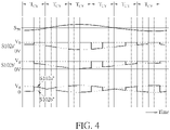
- FIG. 4 illustrates a 2 nd type of membrane driving signals S102a' and S102b'.
- the membrane portions 102a and 102b may be driven by the membrane driving signals S102a' and S102b', respectively.
- the membrane driving signals S102a' and S102b' are SEAM driving signals, which are unipolar with respect to the bias voltage V B .
- first pulses within the driving signal S102a' and second pulses within the driving signal S102b' are mutually interleaved, and have coincidence transition edges and opposite transition polarities, as shown in FIG. 4 .
- Details of the unipolar SEAM driving signal may be referred to US Patent No. 10,771,893 , which are not narrated herein for brevity.
- FIG. 4 also illustrates a 3 rd type of membrane driving signals S102a" (solid line in the bottom) and S102b" (dashed line in the bottom, together with S102a”).
- the membrane portion 102a may be driven by the membrane driving signal S102a" and the membrane portion 102b may be driven by the membrane driving signal S102b".
- a sum of the membrane driving signals S102a” and S102b” may be a constant.
- the constant may be the voltage level V B (if eq.
- first pulses within the driving signal S102a" and second pulses within the driving signal S102b" have coincidence transition edges and opposite transition polarities, which may be observed from FIG. 4 .
- a first interval (which may be a first half of the operating cycle T CY )
- the membrane driving signal pair (S102a, S102b)/(S102a', S102b')/(S102a", S102b") to the membrane portions 102a and 102b
- the membrane portions 102a may be actuated to move toward a positive Z direction
- the membrane portions 102b may be actuated to move toward a negative Z direction.
- the membrane portion 102a may be actuated to compress a first part/volume 105a (on top of the membrane portion 102a) within the chamber 105 and the membrane portions 102b may be actuated to expand a second part/volume 105b (on top of the membrane portion 102b) within the chamber 105, such that a first air pressure gradient (indicated by the block arrow 116 in FIG. 1 ) is formed from the first part/volume 105a toward the second part/volume 105b.
- the membrane portions 102b may be actuated to move toward the positive Z direction and the membrane portions 102a may be actuated to move toward the negative Z direction.
- the membrane portion 102b may be actuated to compress the second part/volume 105b and the membrane portions 102a may be actuated to expand the first part/volume 105a, such that a second air pressure gradient (opposite to 116, not shown in FIG. 1 ) is formed from the second part/volume 105b toward the first part/volume 105a.
- a pressure-gradient direction of the air pressure gradient (e.g., 116 shown in FIG. 1 ) generated by the membrane structure 12, including the membrane portions 102a and 102b, is parallel to the X-direction shown in FIG. 1 .
- a propagation direction of the air wave AW propagating within the chamber 105 is also parallel to the X-direction. That is, the pressure-gradient direction is parallel to the air-wave propagation direction.
- the pressure-gradient direction which is parallel to the X-direction, is perpendicular to a membrane displacement direction of the membrane structure 12, largely in the Z-direction, wherein the membrane displacement direction refers to a direction which the membrane is actuated to move toward.
- the pressure-gradient direction is parallel to the XY-plane, the plane of the membrane structure, and is orthogonal to the direction of the membrane displacements (Z).
- the pressure-gradient direction generated by the membrane structure
- the membrane structure may be regarded as being substantially parallel to the membrane structure and/or substantially perpendicular/orthogonal to the direction of the membrane displacements/movement.
- the opening(s) is suggested to be located at or near the air-pressure antinode(s) of the standing wave.
- the opening may be formed spatially on a location where a peak of the air/standing wave is achieved, wherein the peak of the air/standing wave herein may be in terms of air pressure (for APPS application).
- air pressure within the chamber may be expressed as a single-variable function p ( x ) or a two-variable function p ( x, t ) , where x denotes variable in X-axis and t denotes variable in time-axis.
- the peak may be interpreted as a local maximum or a local minimum of p ( x )/ p ( x, t 0 ) over x-axis.
- the openings 112 and 114 are formed near the side walls 804L and 804R, since the air-pressure antinodes of standing wave will be located at the side walls 804L and 804R.
- valve opening(s) in order to enhance the air pulse generation efficiency, is suggested to be formed during an interval in which a peak pressure of the air wave is achieved at the locations of the valve opening, such as illustrated by 112 and 114 of FIG.1 .
- the peak may be interpreted as a local maximum or a local minimum of p ( x )/ p ( x 0 , t ) over t -axis.
- time intervals of the opening 112 being formed i.e., the valve portion 101 being actuated to be opened or the valve 101 being opened
- time intervals of the opening 114 being formed i.e., the valve portion 103 being actuated to be opened or the valve 103 being opened
- the opening 112 is formed during a (first) interval T 1
- the opening 114 is formed during a (second) interval T 2 .
- the first opening 112 is formed within the first interval T 1 during which a first peak pressure pk 1 of the air wave AW at a first location (corresponding to the sidewall 804L) is achieved; the second opening 114 is formed within the second interval T 2 during which a second peak pressure pk 2 of the air wave AW at a second location is achieved.
- the opening frequency of the valves 101 and 103 equals the operating frequency f CY , in the embodiment shown in FIG. 2 .
- the first interval T 1 (representing the opening interval of the valve 101) covers one half of the operating cycle T CY
- the interval T 1 or T 2 may be slightly shorter or longer than T CY /2 (for example, within ⁇ 10% or ⁇ 20%).
- first interval T 1 (representing the opening interval of the valve 101) may cover a first over/under-pressure interval during which air pressure P112, produced by the membrane movement, is greater/smaller than a certain pressure P th , where the first over/under-pressure interval overlaps with T 1 in the embodiment illustrated in FIG. 2 .
- second interval T 2 (representing the opening interval of the valve 103) may cover a second over/under-pressure interval during which air pressure P114, produced by the membrane movement, is greater/smaller than the certain pressure P th , where the second over/under-pressure interval overlaps with T 2 in the embodiment illustrated in FIG. 2 .
- the air-pulse generating device 890 generate positive/negative air pulses during the valve opening intervals T 1 and T 2 , where the positive/negative air pulses herein may be propagated from the chamber 105 to ambient during the valve opening interval(s).
- the AW pressure wave generated by driving waveform S102a'/S102b' of FIG.4 will be simple AM while the AW pressure wave generated by driving waveform S102a/S102b of FIG.3 or S102a"/-S102a” of FIG.4 will be DSB-SC (double-sideband, suppress carrier).
- the timing relationship shown in FIG.2 corresponds to a simple AM modulated AW pressure wave and peaks pk1, pk2 will not cross the line of P th .
- pk1, pk2 will cross the line of P TH whenever the polarity of S IN changes, at which time over-pressure becomes under-pressure and vice versa.
- the total pressure within the chamber may have two component pressures: one is produced by the membrane movement, the other is produced by the valve movement. Either of both components may be in the form of standing wave.
- the pressures P112 and P114 shown in FIG.2 only refer to component pressures produced by the membrane movements.
- valve portion 101 may form the opening 112 in/during a plurality of first valve opening intervals, and the air pressure P112 may be greater than the certain pressure P th in/during a plurality of first over-pressure intervals.
- the plurality of first valve opening intervals (of the valve 101) and the plurality of first over-pressure intervals (of pressure P112) are temporally aligned or overlapped, where the first valve opening intervals (of the valve 101) and the first over-pressure intervals (of pressure P112) are annotated as T 1 in FIG. 2 .
- valve portion 103 may form the opening 114 in/during a plurality of second valve opening intervals and the air pressure P114 may be greater than the certain pressure P th in a plurality of second over-pressure intervals.
- the plurality of second valve opening intervals (of the valve 103) and the plurality of second over-pressure intervals (of pressure P114) may be also temporally aligned or overlapped, where the valve opening intervals (of the valve 103) and the over-pressure intervals (of pressure P114) are annotated as T 2 as in FIG. 2 .
- a plurality of first time intervals and a plurality of second time intervals being temporally aligned or overlapped may refer that, 1) the plurality of first time intervals and the plurality of second time intervals are temporally arranged (or temporally appear) at the same frequency; or 2) a first time interval and a second time interval with which the first time interval overlaps, forming an overlapped region, and a length of the overlapped region is at least 50% of a length of the first (or second) time interval.
- the air-pulse generating device 890 may produce a plurality of first air pulses AP 1 (shown as P707L in FIG. 2 ) at the port 707L via the opening 112, and produce a plurality of second air pulses AP 2 (shown as P707R in FIG. 2 ) at the port 707R via the opening 114.
- a time corresponding to the peak valve opening of Z101/Z103 is preferably aligned to a time corresponding to the peak pressure of P112/P114 produced by the membrane movement.
- T 1 in FIG. 2 may denote, respectively: the first valve opening intervals of the valve 101 (in Z101's perspective); first membrane movement intervals of the membrane portions 102a (in Z102a's perspective) and 102b (in Z102b's perspective), creating a pressure gradient (vector) directing from volume 105a, atop membrane portion 102a, towards volume 105b, atop membrane portion 102b; the first over-pressure intervals (in P112's perspective); and first duty periods of the first air pulses at port 707L, AP 1 .
- the second valve opening intervals of the valve 103 in Z103's perspective
- second membrane movement intervals of the membrane portions 102a in Z102a's perspective
- the membrane portion 102b in Z102b's perspective
- creating a pressure gradient (vector) directing from volume 105b, atop membrane portion 102b, towards volume 105a, atop membrane portion 102a
- the second over-pressure intervals in P114's perspective
- second duty periods of the second air pulses at port 707R, AP 2 may denote, respectively: the second valve opening intervals of the valve 103 (in Z103's perspective); second membrane movement intervals of the membrane portions 102a (in Z102a's perspective) and the membrane portion 102b (in Z102b's perspective), creating a pressure gradient (vector) directing from volume 105b, atop membrane portion 102b, towards volume 105a, atop membrane portion 102a; the second over-pressure intervals (in P114's perspective), and second duty periods of the
- FIG. 2 illustrates, the first valve opening intervals of the valve 101, the first chamber pressure gradient intervals, the movements of membrane portions 102a and 102b, the first over-pressure intervals and the first duty periods of the first air pressure pulses AP 1 are temporally aligned (peak-to-peak) and overlapped (period wise). Similarity, the second valve opening intervals of the valve 103, the second chamber pressure gradient intervals, the movements of membrane portions 102a and 102b, the second over-pressure intervals (in P114's perspective), and the second duty periods of the second air pressure pulses AP 2 are temporally aligned (peak-to-peak) and overlapped (period wise).
- P707L may be interpreted as a half-wave rectified version of P112, rectified by the timing varying impedance associated with valve 101 movement Z101.
- waveforms P114 and P707R may be interpreted as a half-wave rectified version of P114, rectified by the timing varying impedance associated with valve 103 movement Z103.
- the waveform P890, the summing the waveforms P707L and P707R and representing the on-axis output acoustic pressure of the device 890, may be interpreted as a full-wave rectified version of P112 or P114.
- the plurality of first air pulses AP 1 are produced at a first (air) pulse rate APR 1 corresponding to the operating frequency f CY .
- the plurality of second air pulses AP 2 are produced at a second (air) pulse rate APR 2 corresponding to the operating frequency f CY .
- the air-pulse generating device 890 produces a plurality of aggregated air pules AP.
- the plurality of aggregated air pules AP comprises the first air pulses AP 1 with the first pulse rate APR 1 and the second air pulses AP 2 with the second pulse rate APR 2 .
- the aggregated air pules AP is produced at an overall (air) pulse rate PRO.
- the overall pulse rate PRO is twice of the pulse rate APR 1 (or APR 2 ).
- the action of the membrane movement can be compared to the AM radio station which creates EM wave amplitude modulated by sound signal and radiates the AM EM (electromagnetic) wave into the air.
- device 890 instead of EM wave, device 890 generates amplitude modulated ultrasound wave and transmits such AM ultrasound wave into chamber 105.
- Such ultrasound wave is further amplified, at the location of the valve, by the standing wave construct of chamber 105.
- the standing wave construct of chamber 105 is analogous to an EM waveguide where the signal strength is maximized by locating the port(s) at the node(s) and antinode(s) of the waveguide.
- the signal received at the location of the valve is then demodulated by the periodical operation of the valve(s), which is analogous to the synchronous local oscillator of an AM receiver, and the nonlinear characteristics of Z VALVE , which is analogous to the mixer of an AM receiver and generate the output, P707R/P707R, by dividing P112/P114 by the impendence Z VALVE ( t ) of its corresponding valve.
- 1 ⁇ 2 ⁇ S IN represents demodulated component on the baseband; while the 2 nd term in eq. 3, 1 ⁇ 2 ⁇ S IN ⁇ cos(2 ⁇ t ), represents component in the ultrasonic band.
- a first energy of the 1 st term within the baseband is twice of a second energy of the 2 nd term.
- the baseband herein refers to a frequency band of the input audio signal S IN , and this baseband covers/overlaps with human audible frequency band.
- material of oxide substrate underneath the valves 101, 103, the membrane portions 102a, 102b may be removed by photo lithography process/processes, and supports 110 and walls 111 may be formed.
- Si or POLY layer(s) may be etched to form openings/slits.
- Such slits create free moving ends on the valve 101/103 (e.g., these slits may form the opening 112/114 when the displacement of the free-moving ends of the valves exceed Z O/C ).
- slits can increase the compliance of the membrane portion 102a/102b (e.g., by forming slits 113a, 113b on the membrane portions 102a, 102b).
- FIG. 5 is a schematic diagram illustrating a top view of the air-pulse generating device 890 shown in FIG. 1 .
- the air-pulse generating device 890 may (optionally) include cross linked beams 871, 872 to break down the (long) valves 101, 103 or the (long) membrane portions 102a, 102b into shorter pieces and to reinforce the supports 110 and 891.
- the air-pulse generating device 890 may (optionally) have slot(s) 873, which may be created by widening one slit on a membrane portion to function as an airflow pathway to allow pressure to be release.
- a slit generally has a width corresponding to the etching resolution of a MEMS fabrication process, such as a width of 0.5 ⁇ 1.8 ⁇ M over 3 ⁇ 7 ⁇ M-thick Si membrane; a slot refers to a line geometry width that is not restricted to the limits of the MEMS fabrication process.
- FIG. 7 is a schematic diagram of a cross sectional view of an air-pulse generating device 850 according to an embodiment of the present application.
- 2 air-motion antinodes exist within the chamber 105 (for instance, at/near a quarter (1/4) of the width W 105 from either side wall 804L or side wall 804R); 3 air-motion nodes locate at the center of the chamber 105 and near the side walls 804L, 804R; 2 air-pressure nodes exist within the chamber 105 (for instance, at/near a quarter (1/4) of the width W 105 from either side wall 804L or 804R); 3 air-pressure antinodes locate at the center of the chamber 105 and the side walls 804L, 804R.
- the curve W102 schematically representing pressure distribution within the chamber 105 over time may be caused by the movement of membrane portions 102c and 102d of the air-pulse generating device 830 and symmetrical relative to a center line 703.
- the valve opening 112 of the air-pulse generating device 850 may therefore be located at/near a center location between the side walls 804L and 804R, since an air-pressure antinode is located at the center of the chamber 105 (or the width W 105 ).
- opening(s) of air-pulse generating device(s) may also be at/near any air-pressure antinode between the two side walls causing resonance.
- the demodulation operation of the valves 101 and 103 will produce pulses of airflow which will accumulate across consecutive pulses, causing a long-term net air mass change inside chamber 105 and increase/decrease the pressure P0 within the chamber 105. Since such back pressure will cause the output SPL to drop, it is therefore suggested to release such pressure.
- the membranes 102e and 102f each comprise of 1 single piece of thin flap, attached to their respective support 110.
- one or multiple vent(s) 713T can be created on the top cap, at the location(s) of the air-pressure node(s), for example, at a distance of W 105 /4 away from side walls 804L and 804R.
- vents 713T may suffice for the back-pressure release purpose, however, for the consideration of optimal balancing of air pressure within chamber 105, it is generally a good practice to have a pair of vents 713T, positioned in a center-mirroring fashion, as illustrated in FIG.7 .
- pressure pulses of the acoustic sound (e.g., the acoustic sound P890) out of the valves 112 and 113 have the same polarity, which combine together to increase/decrease the pressure P0 within the chamber 105. Therefore, vent openings 713T on the top plates, located at or near the air-pressure node, as indicated by alignment to the position where air-pressure profile W102 crosses P0, is created to allow airflow to pass through, releasing the pressure build up due to the demodulation operation of the valves 101 and 103.
- the length and width of the vent opening(s) 713T may be adjusted to form a suitable acoustic low pass filter (LPF) with the volume of the chamber 105.
- the location of the vent opening(s) 713T may be at air-pressure node(s), relative to operating frequency f CY , where the amplitude of frequency components corresponding to the standing wave is nearly zero.
- an acoustic notch filter is formed and the pressure corresponding to the amplitude modulated standing wave may be suppressed near/at the vent opening(s) 713T inside the chamber 105, and only the pressure change due to the demodulation operation may be present near/at the vent opening(s) 713T.
- the vent opening 713T of the air-pulse may be positioned approximately at a quarter of the width W 105 (W 105 /4) from either of the side walls 804R and 804L, which is different from the device operating in the 1 st mode resonance (e.g., the device 890), where the vent opening 713T (of the air-pulse generating device 890) may be near the midpoint between the two side walls 804R and 804L.
- the structure of an air-pulse generating device 850 may be altered according to different design consideration.
- the membrane 102e/102f may have two membrane sub-portions, or 2-pieces, like membrane 102a/102b or 102c/102d does, but is not limited thereto.
- the maximum Z-direction displacement of 1-piece membrane construct, such as 102e/102f in FIG.6 needs to be significantly smaller than the thickness (a Z-direction value) of 102e/102f to avoid leakage of the air pressure inside chamber 105.
- the 2-piece per membrane construct since the two sub-portions always moves in tandem, such Z- direction membrane displacement limitation does not exist, meaning larger displacement may be possible and therefore lead to improved unit-device-area effectiveness (SPL per meter).
- valve portions 101 and 103 illustrated in FIG. 7 may be considered as a virtual valve.
- a slit formed between the valve portions 101 and 103 may become a temporarily formed/opened valve opening (112') when the valve portions 101 and 103 is sufficiently actuated.
- the temporarily formed/opened valve opening is formed periodically. When the opening is opened, the chamber and ambient environment are connected via the opening (112'). When the opening is not opened, air flowing through the slit is negligible or less than a threshold.
- virtual valve temporaryly formed opening
- US Patent No. US 11,043,197 which is not narrated herein for brevity.
- pressure gradients are also generated in the device 850 via membrane movement and the nature of standing wave.
- the membrane portions 102e and 102f are actuated to move in an in-phase fashion, referring that at a certain time, both the membrane portions 102e and 102f are actuated to move upward (or downward).
- dashed lines of the curves U102 and W102 are corresponding to the time to and solid lines of the curves U102 and W102 are corresponding to the time t 1 .
- the membrane portions 102e and 102f are actuated to move upward (in positive Z direction), pressure gradients are generated in inward direction (in X direction), as illustrated by the slope of dashed line of W102.
- the membrane portions 102e and 102f are actuated to move downward (in negative Z direction), pressure gradients are generated in outward direction (in X direction), as illustrated by the slope of solid line of W102.
- the membrane movement directions are substantially perpendicular to the pressure gradient directions.
- the structure/mechanism of device 890/830/850 may be reproduced/adapted for an air movement or fan application.
- an air movement is the airflow related to the kinetic movement of air particles, as that of wind, and is produced by the displacement of membrane portion(s), corresponding to membrane portions 102a ⁇ 102d/102 of the air-pulse generating device 890/830/850.
- air particles within the device may be described mainly according to fluid dynamics or aerodynamics; in contrast, in an air-pulse (APPS) generating application/mode of these devices, the behavior of air within the device may be described mainly according to acoustics.
- ADS air-pulse
- valve opening(s) such as the openings 112 and 114 illustrated in device 890/830/850, may be formed spatially on a location, and temporarily in time, such that the air motion is maximized, wherein the peak of the air motion may be in terms of the velocity of the air moved or in terms of the volume of air moved.
- Driving signal(s) of the device for the air-flow generation or fan application differs from that of the APPS application.
- device 890 may actuate its two membranes (102a and 102b) to move synchronously, by applying the same driving signal to both membrane 102a and 102b, to create a pressure difference between the volume inside chamber 105 and the ambient outside of device 890.
- device 890 would actuate its two membranes (102a and 102b) to move symmetrically, in opposite direction(along Z axis), by applying two interleaved (such as S102a, S102b) or polarity inverted (such as S102a", -S102a”) driving signals to membrane 102a and 102b, to create pressure gradient (vector 116) within chamber 105, atop the two membranes.
- two interleaved such as S102a, S102b
- polarity inverted such as S102a", -S102a
- the operating frequency may be selected to produce a standing wave of mode n within chamber.
- the conversion rate of membrane movement into airflow generally increases as the ratio ⁇ CY /W chamber increases, where W chamber is the chamber width of the device, corresponding to width of the chamber 105, W 105 , of the air-pulse generating device 890/830/850.
- the conversion rate of membrane movement into airflow typically increases when the pressure within the chamber of the air-flow generating device for the air movement or fan application (corresponding to the chamber 105 of the air-pulse generating device 890/830/850) becomes more uniform, exactly opposite to the desire to maximize the pressure gradient (or the nonuniformity of the pressure within chamber 105) of the air-pulse generating device 890/830/850.
- the width of the membrane portion may increase from 0.94mm to 1.44mm
- the width of the valve portion may increase from 0.46 to 0.73mm
- an air-pulse generating device for the air movement or fan application with the resonance frequency of 24KHz for both the membrane portion(s) and the valve portion(s) and driving both membrane portions of the air-pulse generating device for the air movement or fan application with the same waveform at 24KHz may be suitable for air moving applications while the air-pulse generating device 890, where the membrane portion 102a and 102b are driven by interleaved waveforms S102a', S102 b' or symmetrical waveforms S102a", -S102a" to produce near-0 net air movement over each operating cycle T CY , may be optimized for sound production applications and not suitable as an air movement apparatus.
- the chamber width (in X direction) W 105 may be equal or close to n /2 ⁇ CY (where n is a small positive integer) in order to maximize its acoustic output by leveraging chamber resonance (i.e. standing wave); on the other hand, for air movement applications, the chamber width (in X direction) of an air-pulse generating device for the air movement or fan application may be much smaller than ⁇ CY /2 to maximize the conversion rate of membrane movement to airflow.
- FIG. 8 is a schematic diagram of a cross sectional view of an air-pulse generating device 880 according to an embodiment of the present application.
- the membrane structure 12 of the air-pulse generating device 880 includes one membrane portion, which is divided into membrane subparts 102e', 102f' and 102g.
- the membrane subparts 102e' and 102g may be differentiated according to slits 113e and 113f on the membrane portion.
- the membrane structure 12 of the air-pulse generating device 880 with the membrane subparts 102e' and 102g may serve/function as the membrane portions 102a and 102b of the air-pulse generating device 890 (or the membrane portions 102c and 102d of the air-pulse generating device 830).
- the membrane subparts 102e' and 102g may be driven by a pair of membrane driving signals similar to the membrane driving signal pair (S102a, S102b)/(S102a', S102b')/(S102a", S102b"), such that the membrane subparts 102e' and 102g may move almost oppositely to have symmetrical membrane displacements. Similar to the membrane portion 102a bending downwards and the membrane portion 102b bending upwards, the membrane subparts 102e' and 102f' may be curved concavely to bend downwards while the membrane subparts 102f and 102g may be curved convexly to bend upwards, and vice versa.
- FIG. 9 is a schematic diagram of a cross sectional view of an air-pulse generating device 800 according to an embodiment of the present application.
- the membrane structure 12 of the air-pulse generating device 800 includes membrane portions 102g and 102h, which are anchored on the support 110 at the center of the air-pulse generating device 800.
- the slits/tips of the membrane portions 102g and 102h are located close to the side wall 804L and 804R.
- the valves 101 and 103 of the air-pulse generating device 890/830/850/880 are absent from the air-pulse generating device 800.
- the membrane portions 102g and 102h may provide the pressure regulation function of the valves 101, 103 of the air-pulse generating device 890 and the pressure generation function of the membrane portions 102a, 102b of the air-pulse generating device 890 by utilizing the slits between the membrane portions 102g, 102h and the walls 111 to perform the AM ultrasonic carrier rectification function of the openings 112, 114 of the valves 101, 103 of the air-pulse generating device 890.
- the membrane portion 102g may vibrate to form opening 112g functioned as the opening 112 of the valve 101 and meanwhile create the maximum/minimum change in pressure (e.g., the first peak pressure pk 1 ).
- the membrane portion 102h may vibrate to form the opening 114h functioned as the opening 114 of the valve 103 and meanwhile create the maximum/minimum change in pressure (e.g., the second peak pressure pk 2 ).
- waveforms Z102a, Z102b represent displacement of the membrane portions 102g, 102h respectively; waveform P707L, P707R represent air pressure at the ports 707L, 707R (out of the chamber 105) respectively.
- a negative bias voltage may be applied to bottom electrode(s) of actuator(s) of the membrane portion 102g/102h, such that the position of (the tip of) the membrane portion 102g/102h in the Z direction is lifted to be equal to or slightly above the displacement level Z O/C when the input AC voltage is 0V.
- Z 0AC may be positive. If the position of (the tip of) the membrane portion 102g/102h in the Z direction is below the displacement level Z O/C when the input AC voltage is 0V, Z 0AC may be negative, and a clipping phenomenon similar to class-B amplifiers may occur to low level input signal(s). In the clipping phenomenon, the membrane portion 102g/102h may not be fully opened.
- Z 0AC may be set to a small positive value to reduce the second term 2•Z 0AC 2 in eq. 5a and the inaudible second term 2•S IN •sin( ⁇ •t)•Z 0AC in eq. 5b.
- Z 0AC may range between 1% ⁇ 10% of the maximum membrane displacement.
- linearity compensation may be performed by a DSP function block embedded within a host processor.
- the membrane portion 102g/102h may be slightly open when the input AC voltage is 0V.
- the membrane driving signal S102a, S102b)/(S102a', S102b')/(S102a", S102b"
- at least one of the openings 112g, 114h may be slightly open/formed at any time. Therefore, the pressure change inside the chamber 105 due to the rectification effect of the openings 112g, 114h may be balanced, and the vent opening(s) 713T or the wider slit openings 113a*/113b* may be absent from the air-pulse generating device 800.
- the effect of full-wave rectification and synchronous demodulation may be produced by the air-pulse generating device 800.
- the maximum acoustic pressure may occur simply as a result of the physical location of the openings 112g, 114h of the membrane portions 102g, 102h and the symmetrical membrane driving signals (S102a, S102b)/(S102a', S102b')/(S102a", S102b"), which drive the actuators of the membrane portions 102g, 102h to cause the maximum displacements near the side walls 804L and 804R.
- the membrane portion 102g may be actuated to compress the first part/volume 105a (on the top of the membrane portion 102g) within the chamber 105 to maximum the local pressure.
- the membrane portions 102h may be actuated to expand the second part/volume 105b (on the top of the membrane portion 102h) within the chamber 105 to minimum the local pressure.
- the pressure profile over time within the part/volumes 105a and 105b may be identical to that of a standing wave in the 1 st mode resonance.
- the air-pulse generating device 800 may achieve full-wave rectification and synchronous demodulation without the resonance of the chamber 105, thereby increasing flexibility in the design of an air-pulse generating device.
- the output of the air-pulse generating device 800 may benefit from the standing wave of such resonance.
- the width W 105 of the chamber 105 of the air-pulse generating device 800 equals half of the wavelength ( ⁇ /2) corresponding to the operating frequency f CY
- a pressure profile similar to that of a standing wave may be established by the movements of the membrane portions 102g and 102h and therefore enhance the output caused by the standing wave having already established within the chamber 105.
- the air pulse generating device 890/850/830 do not generate a pair of out-of-phase baseband radiations, as produced by a conventional speaker (namely, a front radiation and a phase-inverted back radiation), the air-pulse generating device 890/850/830 do not require any back enclosure (whose purpose is to contain or transform to the back radiation and prevent the phase inverted back radiation from cancelling out the front radiation) as a conventional speaker does. Therefore, the air pulse generating device 890/850/830, which produces sound, can be enclosure-less.
- the air-pulse generating device 890 produces two radiations that are in-phase instead of 180° out of phase.
- the phase of acoustic energy is properly phase aligned and the ultrasonic radiation is transformed to double the baseband output SPL, increases the utilization rate of the total acoustic energy, achieve effective demodulation of ultrasonic AM signal while obliterate the need for an enclosure.
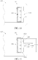
- FIG. 10 is a schematic diagram of the air-pulse generating device 890 disposed within a construct A00 according to an embodiment of the present application.
- FIG. 11 is a schematic diagram of the air-pulse generating device 890 disposed within a construct A30 according to an embodiment of the present application.
- the acoustic air pressure measured at the ports 707L and 707R of the air-pulse generating device 890 may include not only the demodulated AM ultrasonic waves P707L and P707R but also ultrasonic waves generated by the motion of the valves 101 and 103.
- the symmetrical movements of the valves 101 and 103 may be characterized as a dipole.
- the superposition of the ultrasonic waves generated by the motion of the valves 101 and 103 may peak along the plane of the valves 101 and 103 and become null on the center plane between the side walls 804L and 804R.
- the construct A00/A30 may be configured to minimize the ultrasonic waves generated by the motion of the valves 101 and 103 and thus served as an acoustic filter.
- the construct A00 may include a funnel structure A05 configured to filter out the ultrasonic waves generated by the motion of the valves 101/103.
- the funnel structure A05 may have a wide opening on the inside of the construct A00, sloping sides, and a narrow tube near the outside of the construct A00.
- the wide opening of the funnel structure A05 may be smaller than the width W 105 of the chamber 105.
- the funnel structure A05 may merge the output from the ports 707L and 707R, causing the ultrasonic waves produced by the symmetrical movement of the valves 101 and 103 to annihilate each other and leaving behind the wave P890, which is the sum/superposition of the waves P770L and P770R.
- the construct A30 may include an external chamber A06 and a port A07 serving as the output port for the construct A30.
- the width Wa06 between side walls A06T, A06B of the external chamber A06 may equal the width W 105 of the chamber 105 (e.g., half of ⁇ CY ), such that a standing wave may occur at both the frequency f CY (for 1 st mode resonance) and the frequency 2•f CY (for 2 nd mode resonance).
- the width Wa07 of the port A07 may be smaller than the width W 105 of the chamber 105.
- the width Wa07 of the port A07 may be equal to half of the width W 105 of the chamber 105 or a quarter of ⁇ CY .
- the construct A30 is configured to filter out the ultrasonic waves generated by the motion of the valves 101/103.
- the acoustic energy may reside in the 1 st mode resonance of the external chamber A06 with the air-pressure node at/near the midpoint between the side walls A06T and A06B, and the pressure of the standing wave may be merged to zero over the width Wa07 of the port A07.
- the acoustic energy may reside in the 2 nd mode of the external chamber A06 with an air-pressure antinode at/near the midpoint between the side walls A06T and A06B, which is also the center of the port A07, and the maximum output pressure may be produced when the pressure of the standing wave is integrated over the width Wa07 of the port A07.
- the external chamber A06 may remove the ultrasonic spectral component at the frequency f CY by the 1 st mode resonance and pass ultrasonic spectral component at the frequency 2•f CY (namely, the wave P890) by the 2 nd mode resonance.
- the construct A30 may include a film A08, which may be made of aquaphobia material.
- the film A08 may be place within the port A07 to function both as a protective means (to prevent dust, vapors and moisture from entering) and as acoustic resistance (to attenuate the remaining ultrasonic spectral component at the frequency 2•f CY by forming a low-pass filter with the volume of the external chamber A06).
- FIG. 12 is a schematic diagram of a mobile device A60 according to an embodiment of the present application.
- Two air-pulse generating devices A02 and A03 each of which may be any of the air-pulse generating devices 890/850/830, are mounted onto an edge A01 of the mobile device A60 such as a smartphone or notepad.
- the ports 707L and 707R of the air-pulse generating devices A02, A04 may face outward, and the ultrasonic acoustic wave produce by the air-pulse generating devices A02, A03 may pass through orifice-arrays A04, A05.
- the mobile device A60 may utilize the structure of the construct A00 or A30 to remove the ultrasonic spectral component at the frequency f CY produced by the motion of the valves 101 and 103 while allowing the wave P890 at the frequency 2•f CY to pass through.
- the film A08 of the construct A30 may reduce the remaining ultrasonic spectral component around the frequency 2•f CY further.
- FIG. 13 is a schematic diagram of a cross sectional view of an air-pulse generating device 300 according to an embodiment of the present application. Similar to the air-pulse generating device 890, when a standing wave is formed with the chamber 105 of the air-pulse generating device 300, the movements of the membrane portions 102c and 102d of the air-pulse generating device 300 is symmetrical and may produce near 0 net air movement. Because of the near 0 net air movement over each operating cycle T CY , most of the energy exerted by the membrane portions 102c/102d becomes acoustic energy (in the form of air pressure gradient or a standing wave) and near zero energy becomes kinetic energy (in the form of air mass movement, i.e., wind).
- acoustic energy in the form of air pressure gradient or a standing wave
- kinetic energy in the form of air mass movement, i.e., wind
- FIG. 14 is a schematic diagram of a cross sectional view of an air-moving device 100 for moving air volume from one port of the device to another port, according to an embodiment of the present application.
- the interleaved valve driving signals S101, S103 may be configured to open the valve portions 101, 103 in a time interleaved manner, or 180° out of phase, and produce air movement either from port 107 to port 108, or from port 108 to port 107.
- valve 101/103 is open and valve 103/101 is closed when membrane 102 moves in a positive Z direction (+Z direction) to compress the volume within chamber 105, the air will flow out of chamber 105 via port 107/108.
- valve 101/103 is opened and valve 103/101 is closed when membrane 102 moves in a negative Z direction (-Z direction) to expand the volume of chamber 105, the air will flow into chamber 105 via port 107/108.
- the cap 104 of the air-moving device 100 may function as a heat dissipation plate/pad, making physical contact with heat generating components such as notebook central processing unit (CPU) or smartphone application processor(s) (AP), but is not limited thereto.
- the cap 104 may be made of heat conducting material such as aluminum or copper.
- fine fins may be formed on the surface of the cap 104 inside the chamber 105, but not limited thereto.
- the cap 104 of the air device 100/300 is replaced by the top plate 804T and the spacers 804L, 804R which also serve as side walls.
- the top plate 804T may be a printed circuit board (PCB) or a land grid array (LGA) substrate and includes metal traces, vias and contact pads which may be otherwise presented on the substrate 109 or the plate 115.
- the thicknesses may be 0.2 ⁇ 0.3mm for the top plate 804T, 0.05 ⁇ 0.15mm for the side walls 804L/804R and 0.25 ⁇ 0.35mm for the wall 111.
- the total thickness of an air-pulse generating device may be 0.6 ⁇ 0.8mm, but not limited thereto.
- pulse interleaving concept disclosed in US Patent No. 10,536,770 may be also applied in the present application.
- multiple air-pulse generating devices e.g., multiple air-pulse generating devices 100
- the driving signals for the air-pulse generating devices 100 may be interleaved to form an interleaved group and raise the effective air pulse rate to a twice higher frequency as a result, away from human audible band.
- pulses of the membrane driving signal of one air-pulse generating device 100 may be interleaved with pulses of the membrane driving signal of another air-pulse generating device 100, such that the aggregated air pulses of one air-pulse generating device 100 may be interleaved with the aggregated air pulses of another air-pulse generating device 100 to increase the effective air pulse rate.
- each pulse of the membrane driving signal of one air-pulse generating device 100 may locate at/near a mid-point between two successive pulses of the membrane driving signal of the other air-pulse generating device 100, such that each aggregated air pulse of one air-pulse generating device 100 locate at/near a mid-point between two successive aggregated air pulses of the other air-pulse generating device 100 to increase the effective air pulse rate.
- two air-pulse generating devices 100 each designed to operate at the operating frequency T CY of 24KHz, may be placed side-by-side or attached back-to-back and driven in interleaved manner, such that the effective air pulse rate becomes 48KHz.
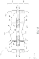
- FIG. 15 is a schematic diagram of an air-pulse generating device 400 according to an embodiment of the present application.
- the air-pulse generating device 400 may be regarded as two air-pulse generating devices 100 and 100' stacked back-to-back.
- two chambers 105 and 105' of the two air-pulse generating devices 100 and 100' are connected together via an opening 116 to form a chamber 106 of the air-pulse generating device 400.
- the air-pulse generating device 400 may comprise a first valve portion 101, a second valve portion 103, a third valve portion 101', and a fourth valve portion 103'.
- a first anchor where the valve portion 101 is anchored on the wall 111 and a second anchor where the valve portion 103 is anchored on the wall 111 are aligned to the X direction; on the other hand, the first anchor and a third anchor where the valve portion 101' is anchored on the wall 111 are aligned to the Z direction.
- valve portions 101 and 103 are symmetric with respect to the YZ plane; on the other hand, the (unactuated) valve portions 101 and 101' (or the valve portions 103 and 103') are symmetric with respect to a second plane (e.g., the XY plane) nonparallel to the YZ plane when the valve driving signal S101 (or S103) applied to the valve portions 101 and 101' drops to zero.
- a second plane e.g., the XY plane
- valve portions 101 and 101' are noncoplanar, while the (unactuated) valve portion 101 and 103 (or the valve portion 101' and 103') may be coplanar when the valve driving signals S101 and S103 applied to the valve portions 101 and 103 drop to zero.
- the displacement profile(s) of the membrane portion 102 (or the valve portions 101, 103) of the air-pulse generating device 400 may be mirror symmetric to the displacement profile(s) of membrane portion 102' (or valve portions 101', 103') of the air-pulse generating device 400.
- the displacement profile(s) of the membrane portion 102 (or the valve portions 101, 103) of the air-pulse generating device 400 may be the same as the displacement profile(s) of membrane portion 102' (or valve portions 101', 103') of the air-pulse generating device 400, such that (the direction and the magnitude of) the displacement of the membrane portion 102 may equal (the direction and the magnitude of) the displacement of the membrane portion 102', causing the pressure fluctuations in the chamber 106 to be cancelled.
- the membrane portion 102 may be parallel to (or be offset to match) the membrane portion 102'.
- the characteristic length ⁇ CY is generally much longer than the dimension of the air-pulse generating device 400. Since the displacement of the membrane portion 102 may equal the displacement of the membrane portion 102', the air-pulse generating device 400 may include only one membrane portion, and one of the membrane portions 102, 102' may be removed, thereby reducing power consumption and improving operation efficiency.
- the output of an air-pulse generating device is related to A(t) ⁇ p(t), where A ( t ) is the area of the opening 112/114, and p ( t ) represents air pressure with the chamber 105.
- the opening 112/114 of the valve 101/103 is directly related/proportional to the intensity of the output of an air-pulse generating device.
- the maximum SPL output is a combination of the maximum of the air pressure p(t) within the chamber 105, produced by membrane movement, and the maximum of the area A(t) of the opening 112/114, produced by valve movement.
- the area A(t) may not change at a rate audible to human hearing, but may be adjusted by changing the valve driving voltage S101/S103 slowly according to the volume or the envelope of the sound being produced.
- the valve driving voltage S101/S103 may be controlled by an envelope detection with an attack time of 50 milliseconds and a release time of 5 seconds.
- the valve driving voltage S101/S103 may be gradually lowered with the (long) release time of 5 seconds.
- the valve driving voltage S101/S103 may be boosted with the (short) 50-millisecond attack time.
- an air-pulse generating device of the present invention may produce an acoustic pressure (or air movement) by first vibrating its membrane structure, subsequently opening/closing its valve structure to filter/reshape the acoustic pressure (or air movement) in response to the occurrence of the maximum/minimum of acoustic pressure (or air velocity), and finally outputting a sound wave (or airflow) under a full-wave rectification effect.
- Synchronous demodulation may be performed by opening/closing its valve structure in a phase-locked and time-aligned manner relative to the occurrence of the maximum/minimum of acoustic pressure (or air velocity) and/or by opening/closing valve portions of the valve structure in a temporally interleaved manner.
Abstract
Description
- The present application relates to an air-pulse generating device and a sound producing method thereof, and more particularly, to an air-pulse generating device and a sound producing method thereof capable of increasing overall air pulse rate, improving sound pressure level, and/or saving power.
- Speaker driver and back enclosure are two major design challenges in the speaker industry. It is difficult for a conventional speaker to cover an entire audio frequency band, e.g., from 20 Hz to 20 KHz. To produce high fidelity sound with high enough sound pressure level (SPL), both the radiating/moving surface and volume/size of back enclosure for the conventional speaker are required to be sufficiently large.
- Therefore, how to design a small sound producing device while overcoming the design challenges faced by conventional speakers is a significant objective in the field.
- It is therefore a primary objective of the present application to provide an air-pulse generating device and a sound producing method thereof, to improve over disadvantages and/or restrictions of the prior art.
- This is achieved by an air-pulse generating device according to the independent claim 1 here below. The dependent claims pertain to corresponding further developments and improvements.
- As will be seen more clearly from the detailed description following below, an embodiment of the present invention provides an air-pulse generating device, comprising a membrane structure and a valve structure; a cover structure, wherein a chamber is formed between the membrane structure, the valve structure and the cover structure; wherein an air wave vibrating at an operating frequency is formed within the chamber; wherein the valve structure is configured to be actuated to perform an open-and-close movement to form at least one opening, the at least one opening connects air inside the chamber with air outside the chamber; wherein the open-and-close movement is synchronous with the operating frequency.
- Another embodiment of the present invention provides a sound producing method, applied in an air-pulse generating device, the method comprising forming an air wave within a chamber, wherein the air wave vibrates at an operating frequency, and the chamber is formed within the air-pulse generating device; and forming at least one opening on the air-pulse generating device at an opening frequency, wherein the at least one opening connects air inside the chamber with air outside the chamber; wherein the opening frequency is synchronous with the operating frequency.
-
-
FIG. 1 is a schematic diagram of an air-pulse generating device according to an embodiment of the present application. -
FIG. 2 is a schematic diagram of a plurality of waveforms according to an embodiment of the present application. -
FIG. 3 is a schematic diagram of a plurality of signals according to an embodiment of the present application. -
FIG. 4 illustrates membrane driving signals according to an embodiment of the present application. -
FIG. 5 is a schematic diagram illustrating a top view of the air-pulse generating device shown inFIG. 1 . -
FIG. 6 andFIG. 7 are schematic diagrams of cross sectional views of air-pulse generating devices according to embodiments of the present application. -
FIG. 8 andFIG. 9 are schematic diagrams of cross sectional views of air-pulse generating devices according to embodiments of the present application. -
FIG. 10 and FIG. 11 are schematic diagrams of the air-pulse generating device shown inFIG. 8 disposed within constructs according to embodiments of the present application -
FIG. 12 is a schematic diagram of a mobile device according to an embodiment of the present application. -
FIG. 13 to FIG. 15 are schematic diagrams of cross sectional views of air-pulse generating devices according to embodiments of the present application. -
FIG. 16 is a schematic diagram of valve movement according to an embodiment of the present application. -
US Patent No. 10,425,732 10,425,732 -
US Patent No. 10,771,893 -
US Application No. 16/802,569 -
US Patent No. US 11,043,197 - In an embodiment, the air-pulse generating device of the present application may be applied in an APPS application, which is configured to produce PAM air pulses at an ultrasonic pulse rate according to APPS sound production principle. In another embodiment, the air-pulse generating device of the present application may be applied in an air movement or fan application, which functions as a fan and is similar to
US Patent No. 10,425,732 -
FIG. 1 is a schematic diagram of a cross sectional view of an air-pulse generating device 890 according to an embodiment of the present application. The air-pulse generating device 890 may be applied within an APPS. The air-pulse generating device 890 comprises amembrane structure 12, avalve structure 11 and acover structure 804. Achamber 105 is formed between themembrane structure 12, thevalve structure 11 and thecover structure 804. The air-pulse generating device 890 produces its (air pressure) output atports FIG. 1 illustrates (solid outlines) themembrane structure 12 in a state in which themembrane structure 12 is (substantially) flat and parallel to XY-plane, and also illustrates (dashed outlines) themembrane structure 12 in an actuated state in which themembrane structure 12 is curved. - The
membrane structure 12 and thevalve structure 11 may have thin film structure, which may, e.g., be fabricated by MEMS (Micro-Electro-Mechanical System) fabrication process using SOI (silicon/Si of insulator) or POI (Poly-Si/polysilicon on insulator) wafers, but not limited thereto. In the embodiment shown inFIG. 1 , themembrane structure 12 comprises afirst membrane portion 102a and asecond membrane portion 102b. Thevalve structure 11 comprises afirst valve portion 101 and asecond valve portion 103. Thecover structure 804 comprises atop plate 804T andside walls chamber 105 is surrounded by/between themembrane portions valve portions top plates 804T, and theside walls portion 101/103 is anchored to supportstructure 110/115 on one end and is free-moving on the other end, where the free-moving end is located close/next toside wall 804L/804R. - The
membrane structure 12 is configured to be actuated, such that an air wave AW is produced. Furthermore, by carefully choosing driving signal(s) fed to themembrane structure 12, the air wave AW may vibrate at an operating frequency fCY and propagates along with a direction (e.g., X-direction) parallel to themembrane structure 12 within thechamber 105. - In a perspective, air wave may be related that the mass of air molecules periodically moves in a back-and-forth direction (e.g., left-and-right in X-direction, in view of X-axis components movement) at a certain time period due to air pressure variation or variation of air-molecule density. Air wave vibrating at a certain frequency may be related to the operating frequency fCY that the certain frequency is a reciprocal of the certain time period, and vice versa.
- The
valve structure 11 is configured to be actuated to perform an open-and-close movement, at an opening frequency, to form at least one opening periodically, where the at least one opening connects the air inside thechamber 105 with the ambient/air outside thechamber 105. Specifically, thevalve portion 101 may be actuated to perform an up-and-down movement (in the Z direction) which cause anopening 112 to form-and-unform, and this is referred to as the open-and-close ofvalve 101. Similarly, thevalve portion 103 may be actuated to perform an up-down movement (in the Z direction) which cause anopening 114 to form-and-unform, and this is referred to as the open-and-close ofvalve 103. The open-and-close movements of thevalve structure 11, including the valve (portions) 101 and 103, (or the opening frequency) would be synchronous with the air wave AW, which is further synchronous with the operating frequency fCY. The open-and-close movements of the valve structure/portion being synchronous with the operating frequency fCY means that, the open-and-close movements of the valve portion/structure is performed (preferably) at the operating frequency fCY, or at a frequency of (M/N)*fCY, wherein both M and N are integers. In an embodiment, the operating frequency is synchronous with a resonance frequency of the membrane structure or a resonance frequency of the valve structure. The open-and-close, up-and-down, form-and-unform movement will be elaborated later. In the following description, thevalve portion 101/103 may be referred to thevalve 101/103 for brevity. - The function of valve opening is similar to that of a variable resistor whose resistance to airflow, ZVALVE, is controlled by the degree of the valve opening. When the valve is closed, i.e. Z101 < ZO/C or Z103 < ZO/C, the magnitude of ZVALVE will be high (Hi-Z). When the valve is opened, i.e. Z101 > ZO/C or Z103 > ZO/C, the magnitude of ZVALVE will be inversely related to the degree of opening, or Z101 - ZO/C or Z103 - ZO/C. The wider a valve is opened, the lower the value of ZVALVE will be and the higher the airflow will be for any given chamber pressure.
- Note that, given the
side walls membrane structure 12 may comprise an incident wave and a reflected wave. In an embodiment, a width of thechamber 105, denoted as W105, or a distance between theside walls chamber 105. - In an embodiment, the distance between the
side walls - In an embodiment, the distance between the
side walls chamber 105. In this case, only 1 air-motion antinode (amplitude reaches peak) exists within the chamber 105 (which may be at a center of the chamber 105); only 2 air-motion nodes (amplitude near 0) locate at theside walls side walls - Herein, in chamber resonance or standing wave perspective, the air-motion antinode represents position at which amplitude of air-molecule velocity/displacement achieves maximum in air-motion over X-axis within the chamber; the air-motion node represents position at which amplitude of air-molecule velocity/displacement achieves minimum in air-motion over X-axis within the chamber (usually 0 movement); the air-pressure antinode represents position at which amplitude of air pressure variation achieves maximum in air pressure over X-axis within the chamber; the air-pressure node represents position at which amplitude of air pressure variation achieves minimum in air pressure over X-axis within the chamber.
- In
FIG. 1 , curves U102 schematically represent displacements of air particles distributed in the X-direction at different times, curves W102 schematically represent pressure distribution within the chamber at different times. For example, dashed lines of the curves U102 and W102 are corresponding to a time t0 and solid lines of the curves U102 and W102 are corresponding to a time t1. P0 inFIG. 1 may refer to an ambient pressure, which may be 1 atm. In an embodiment, to achieve 1st mode (or n=1 mode) resonance, the distance between the between theside walls - Details of the valve movement of 101/103 are further illustrated in
FIG. 16 . At the time t0 (or when t=t0), thevalve 101 is actuated to bend upward such that theopening 112 is opened or formed, and thevalve 103 may be actuated to (substantially) seal theopening 114, which means that theopening 114 is closed or unformed, as shown in the top ofFIG. 16 . On the other hand, at the time t1 (or when t=t1), thevalve 101 may be actuated to (substantially) seal theopening 112, which means that theopening 112 is closed or unformed, and thevalve 103 is actuated to bend upward such that theopening 114 is opened or formed, as shown in the bottom ofFIG. 16 . In an embodiment, at some time t2 (or when t=t2, where t2#t0 and t2#t1), thevalves openings FIG. 16 , corresponding to Z101=ZO/C and Z103=ZO/C as shown inFIG.2 respectively. -
FIG. 2 is a schematic diagram of a plurality of waveforms according to an embodiment of the present application. Waveform Z101 schematically represents displacement in Z-direction of the free-moving end ofvalve portion 101; while waveform Z103 schematically represents displacement in Z-direction of the free-moving end ofvalve portion 103. ZO/C represents a certain level of displacement, and the suffix O/C stands for a line separating the open-state from the close-state. When the displacement of the free-moving end of valve Z101 is larger than (above) the displacement level ZO/C, theopening 112 is formed or thevalve 101 is opened. When the displacement of the free-moving end of valve Z103 is larger than the displacement level ZO/C, theopening 114 is formed or thevalve 103 is opened. When the displacement of the free-moving end of valve Z101 is less than (below) the displacement level ZO/C, theopening 112 is not formed or thevalve 101 is closed. When the displacement of the free-moving end of valve Z103 is less than the displacement level ZO/C, theopening 114 is not formed or thevalve 103 is closed. - Waveform P112 schematically represents air pressure at the opening 112 (within the chamber 105). Waveform P114 schematically represents air pressure at the opening 114 (within the chamber 105). Waveform Z102a represents displacement of the
membrane portion 102a, which may share similar waveform with P112. Waveform Z102b represents displacement of themembrane portion 102b, which may share similar waveform with P114. Waveform P707L schematically represents air pressure (or quantity analogous to air pressure) at theport 707L (out of the chamber 105). Waveform P707R schematically represents air pressure (or quantity analogous to air pressure) at theport 707R (out of the chamber 105). Waveform P890 represents a sum/superposition of P707L and P707R, corresponding to an aggregated on-axis output acoustic pressure of thedevice 890. Waveform Z102a/Z102b whose unit is length, such as µM, generally has different amplitude fromwaveform P1 12/P114 whose unit is pressure, such as Pa. However, since the purpose ofFIG.2 is mainly to illustrate the timing relationship between different parts of the operation, these waveforms are merged inFIG.2 for brevity. -
FIG. 3 is a schematic diagram of a plurality of signals according to an embodiment of the present application. SIN represents an input audio signal. S101/S103 represents a valve driving signal configured to drive thevalve portion 101/103. S102a/S102b represents a membrane driving signal configured to drive themembrane portion 102a/102b. - As can be seen from the plots/waveforms P112 and P114 in
FIG. 2 , P112 and P114 are/comprise amplitude-modulated waveforms, and amplitude-modulated waveform P112/P114 may be expressed as a product of a carrier component and a modulation component, in general. The carrier component, usually expressed as cos(2π f CY t), oscillates at the operating frequency fCY, where fCY = 1/TCY, where TCY denotes an operating cycle. The modulation component, may be expressed as m(t), is reflected by an envelope of the amplitude-modulated waveform (denoted by dotted envelope-curves inFIG. 2 andFIG. 3 ) which is corresponding to the input audio signal SIN. In an embodiment, the modulation component m(t) may be corresponding or proportional to the input audio signal SIN. - The amplitude-modulated waveform P112/P114 may be achieved by driving the
membrane structure 12 by pulse-amplitude modulated driving signal. For example, the membrane driving signal S102a/S102b shown inFIG. 3 driving themembrane portion 102a/102b are pulse-amplitude modulated signal, generated according to the input audio signal SIN. - In other words, the membrane driving signal S102a comprises a first pulse-amplitude modulated (PAM) signal comprising a plurality of first pulses with respect to a certain bias voltage VB. The first pulses are temporally distributed/arranged by the operating frequency fCY. Similarly, the membrane driving signal S102b comprises a second PAM signal comprising a plurality of second pulses with respect to the bias voltage VB. The second pulses are temporally distributed/arranged by the operating frequency fCY.
- In addition, the first pulses comprise first transition edges; while the second pulses comprise second transition edges. The first transition edges of the first pulses within the PAM signal S102a coincide with the second transition edges of the second pulses within the PAM signal S102b. Furthermore, at a certain coincidence time of the first transition edge and the second transition edge, the first transition edge is corresponding to a first transition polarity, and the second transition edge is corresponding to a second transition polarity. The first transition polarity is opposite to the second transition polarity, at the certain coincidence time. Details of the coincidence of the first and second transition edges and the opposition of the first and second transition polarities may be referred to
FIG. 3 of the present application, or also be referred toUS Patent No. US 11,043,197 US 11,051,108 - Note that, the membrane driving signal S102a/S102b driving the
membrane portion 102a/102b is bipolar (or double-ended) with respect to the bias voltage VB, which is not limited thereto. For example,FIG. 4 illustrates a 2nd type of membrane driving signals S102a' and S102b'. Themembrane portions FIG. 4 . Details of the unipolar SEAM driving signal may be referred toUS Patent No. 10,771,893 -
FIG. 4 also illustrates a 3rd type of membrane driving signals S102a" (solid line in the bottom) and S102b" (dashed line in the bottom, together with S102a"). In an embodiment, themembrane portion 102a may be driven by the membrane driving signal S102a" and themembrane portion 102b may be driven by the membrane driving signal S102b". The driving signal S102b" may be obtained from S102a" according to equations expressed as S102b" = VB - S102a" (eq. 1) or S102b" = - S102a" (eq. 2). In other words, a sum of the membrane driving signals S102a" and S102b" may be a constant. The constant may be the voltage level VB (if eq. 1 is applied) or 0V (if eq. 2 is applied). Similar to the membrane driving signals S102a and S102b, first pulses within the driving signal S102a" and second pulses within the driving signal S102b" have coincidence transition edges and opposite transition polarities, which may be observed fromFIG. 4 . - In one perspective, during a first interval (which may be a first half of the operating cycle TCY), by applying the membrane driving signal pair (S102a, S102b)/(S102a', S102b')/(S102a", S102b") to the
membrane portions membrane portions 102a may be actuated to move toward a positive Z direction and themembrane portions 102b may be actuated to move toward a negative Z direction. Hence, during the first interval, themembrane portion 102a may be actuated to compress a first part/volume 105a (on top of themembrane portion 102a) within thechamber 105 and themembrane portions 102b may be actuated to expand a second part/volume 105b (on top of themembrane portion 102b) within thechamber 105, such that a first air pressure gradient (indicated by theblock arrow 116 inFIG. 1 ) is formed from the first part/volume 105a toward the second part/volume 105b. - Conversely, during a second interval (which may be a second half of the operating cycle TCY), the
membrane portions 102b may be actuated to move toward the positive Z direction and themembrane portions 102a may be actuated to move toward the negative Z direction. Hence, during the second interval, themembrane portion 102b may be actuated to compress the second part/volume 105b and themembrane portions 102a may be actuated to expand the first part/volume 105a, such that a second air pressure gradient (opposite to 116, not shown inFIG. 1 ) is formed from the second part/volume 105b toward the first part/volume 105a. - A pressure-gradient direction of the air pressure gradient (e.g., 116 shown in
FIG. 1 ) generated by themembrane structure 12, including themembrane portions FIG. 1 . A propagation direction of the air wave AW propagating within thechamber 105 is also parallel to the X-direction. That is, the pressure-gradient direction is parallel to the air-wave propagation direction. In addition, the pressure-gradient direction, which is parallel to the X-direction, is perpendicular to a membrane displacement direction of themembrane structure 12, largely in the Z-direction, wherein the membrane displacement direction refers to a direction which the membrane is actuated to move toward. Therefore, the pressure-gradient direction is parallel to the XY-plane, the plane of the membrane structure, and is orthogonal to the direction of the membrane displacements (Z). By taking the membrane structure being actuated or deformed into consideration, the pressure-gradient direction (generated by the membrane structure) may be regarded as being substantially parallel to the membrane structure and/or substantially perpendicular/orthogonal to the direction of the membrane displacements/movement. - When a standing wave is formed within
chamber 105, in order to enhance the acoustic output efficiency, the opening(s) is suggested to be located at or near the air-pressure antinode(s) of the standing wave. For the air-pulse generating device 890, the opening may be formed spatially on a location where a peak of the air/standing wave is achieved, wherein the peak of the air/standing wave herein may be in terms of air pressure (for APPS application). - For APPS application, suppose that air pressure within the chamber may be expressed as a single-variable function p(x) or a two-variable function p(x, t), where x denotes variable in X-axis and t denotes variable in time-axis. The peak may be corresponding to a place where the 1st order (partial) derivative being zero, i.e., dp(x)/dx = 0 or ∂p(x, t)/∂x = 0 (to seek optimum spatial location of valve opening). In other words, (for some fixed time t 0) the peak may be interpreted as a local maximum or a local minimum of p(x)/p(x, t 0) over x-axis.
- In this case, for the air-pulse
generating APPS device 890, theopenings side walls side walls - In another aspect, in order to enhance the air pulse generation efficiency, the timing of valve opening(s) is suggested to be formed during an interval in which a peak pressure of the air wave is achieved at the locations of the valve opening, such as illustrated by 112 and 114 of
FIG.1 . The peak pressure timing herein may be corresponding to a time at which the 1st order (partial) time derivative is zero, i.e., dp(t)/dt = 0 or ∂p(x, t)/∂t = 0 (to seek optimum timing, i.e., temporal behavior, of valve opening), given that air pressure within the chamber may be expressed as a single-variable function p(t) or the two-variable function p(x, t). In other words, (for some fixed location x 0, x 0 may be the location ofvalve opening 112 or 114) the peak may be interpreted as a local maximum or a local minimum of p(x)/p(x 0, t) over t-axis. - For example, referring to
FIG. 2 , time intervals of theopening 112 being formed (i.e., thevalve portion 101 being actuated to be opened or thevalve 101 being opened) is illustrated as dotted regions in the plot Z101; time intervals of theopening 114 being formed (i.e., thevalve portion 103 being actuated to be opened or thevalve 103 being opened) is illustrated as cross hatched regions in the plot Z103. Theopening 112 is formed during a (first) interval T1; while theopening 114 is formed during a (second) interval T2. Both intervals T1 and T2 may lie within the operating cycle TCY, meaning that T1 ≤ TCY, T2 ≤ TCY and T1 + T2 ≤ (1+d)×TCY, where TCY = 1/fCY and d <0.5. - To enhance efficiency, the
first opening 112 is formed within the first interval T1 during which a first peak pressure pk1 of the air wave AW at a first location (corresponding to thesidewall 804L) is achieved; thesecond opening 114 is formed within the second interval T2 during which a second peak pressure pk2 of the air wave AW at a second location is achieved. - In one perspective, the opening frequency of the
valves FIG. 2 . - Note that, in the embodiment illustrated in
FIG. 2 , the first interval T1 (representing the opening interval of the valve 101) covers one half of the operating cycle TCY, and the second interval T2 (representing the opening interval of the valve 103) covers another half of the operating cycle TCY, meaning that T1 = T2 ≈ TCY/2 (i.e., let a length of interval Ty be equal to half the length of the operating cycle TCY, then Ty ≈ T1 or Ty ≈ T2), which is not limited thereto. The interval T1 or T2 may be slightly shorter or longer than TCY/2 (for example, within ±10% or ±20%). As long as the opening interval of thevalve 101 covers the first peak pk1 and the opening interval of thevalve 103 covers the second peak pk2, the requirements of present application are satisfied, which is within the scope of the present application. - Furthermore, the first interval T1 (representing the opening interval of the valve 101) may cover a first over/under-pressure interval during which air pressure P112, produced by the membrane movement, is greater/smaller than a certain pressure Pth, where the first over/under-pressure interval overlaps with T1 in the embodiment illustrated in
FIG. 2 . Similarly, the second interval T2 (representing the opening interval of the valve 103) may cover a second over/under-pressure interval during which air pressure P114, produced by the membrane movement, is greater/smaller than the certain pressure Pth, where the second over/under-pressure interval overlaps with T2 in the embodiment illustrated inFIG. 2 . In this case, the air-pulse generating device 890 generate positive/negative air pulses during the valve opening intervals T1 and T2, where the positive/negative air pulses herein may be propagated from thechamber 105 to ambient during the valve opening interval(s). - Note that, the AW pressure wave generated by driving waveform S102a'/S102b' of
FIG.4 will be simple AM while the AW pressure wave generated by driving waveform S102a/S102b ofFIG.3 or S102a"/-S102a" ofFIG.4 will be DSB-SC (double-sideband, suppress carrier). The timing relationship shown inFIG.2 corresponds to a simple AM modulated AW pressure wave and peaks pk1, pk2 will not cross the line of Pth. However, for DSB-SC modulated AW pressure wave, pk1, pk2 will cross the line of PTH whenever the polarity of SIN changes, at which time over-pressure becomes under-pressure and vice versa. - Note that, the total pressure within the chamber may have two component pressures: one is produced by the membrane movement, the other is produced by the valve movement. Either of both components may be in the form of standing wave. The pressures P112 and P114 shown in
FIG.2 only refer to component pressures produced by the membrane movements. - Furthermore, the
valve portion 101 may form theopening 112 in/during a plurality of first valve opening intervals, and the air pressure P112 may be greater than the certain pressure Pth in/during a plurality of first over-pressure intervals. In the embodiment shown inFIG. 2 , the plurality of first valve opening intervals (of the valve 101) and the plurality of first over-pressure intervals (of pressure P112) are temporally aligned or overlapped, where the first valve opening intervals (of the valve 101) and the first over-pressure intervals (of pressure P112) are annotated as T1 inFIG. 2 . - Similarly, the
valve portion 103 may form theopening 114 in/during a plurality of second valve opening intervals and the air pressure P114 may be greater than the certain pressure Pth in a plurality of second over-pressure intervals. The plurality of second valve opening intervals (of the valve 103) and the plurality of second over-pressure intervals (of pressure P114) may be also temporally aligned or overlapped, where the valve opening intervals (of the valve 103) and the over-pressure intervals (of pressure P114) are annotated as T2 as inFIG. 2 . - In the present application, a plurality of first time intervals and a plurality of second time intervals being temporally aligned or overlapped may refer that, 1) the plurality of first time intervals and the plurality of second time intervals are temporally arranged (or temporally appear) at the same frequency; or 2) a first time interval and a second time interval with which the first time interval overlaps, forming an overlapped region, and a length of the overlapped region is at least 50% of a length of the first (or second) time interval.
- By aligning the valve opening intervals and the over-pressure intervals, the air-
pulse generating device 890 may produce a plurality of first air pulses AP1 (shown as P707L inFIG. 2 ) at theport 707L via theopening 112, and produce a plurality of second air pulses AP2 (shown as P707R inFIG. 2 ) at theport 707R via theopening 114. In addition, a time corresponding to the peak valve opening of Z101/Z103 is preferably aligned to a time corresponding to the peak pressure of P112/P114 produced by the membrane movement. - In different perspectives, T1 in
FIG. 2 may denote, respectively: the first valve opening intervals of the valve 101 (in Z101's perspective); first membrane movement intervals of themembrane portions 102a (in Z102a's perspective) and 102b (in Z102b's perspective), creating a pressure gradient (vector) directing fromvolume 105a, atopmembrane portion 102a, towardsvolume 105b, atopmembrane portion 102b; the first over-pressure intervals (in P112's perspective); and first duty periods of the first air pulses atport 707L, AP1. Similarly, T2 inFIG. 2 may denote, respectively: the second valve opening intervals of the valve 103 (in Z103's perspective); second membrane movement intervals of themembrane portions 102a (in Z102a's perspective) and themembrane portion 102b (in Z102b's perspective), creating a pressure gradient (vector) directing fromvolume 105b, atopmembrane portion 102b, towardsvolume 105a, atopmembrane portion 102a; the second over-pressure intervals (in P114's perspective), and second duty periods of the second air pulses atport 707R, AP2. -
FIG. 2 illustrates, the first valve opening intervals of thevalve 101, the first chamber pressure gradient intervals, the movements ofmembrane portions valve 103, the second chamber pressure gradient intervals, the movements ofmembrane portions - In a perspective, by comparing waveforms P112 and P707L, P707L may be interpreted as a half-wave rectified version of P112, rectified by the timing varying impedance associated with
valve 101 movement Z101. Also, by comparing waveforms P114 and P707R, P707R may be interpreted as a half-wave rectified version of P114, rectified by the timing varying impedance associated withvalve 103 movement Z103. The waveform P890, the summing the waveforms P707L and P707R and representing the on-axis output acoustic pressure of thedevice 890, may be interpreted as a full-wave rectified version of P112 or P114. - Referring to plot P707L, the plurality of first air pulses AP1 are produced at a first (air) pulse rate APR1 corresponding to the operating frequency fCY. Referring to plot P707R, the plurality of second air pulses AP2 are produced at a second (air) pulse rate APR2 corresponding to the operating frequency fCY.
- Referring to plot P890, since the first plurality of air pulses AP1 and the second plurality of air pulses AP2 are temporally and mutually interleaved, it can be interpreted that the air-
pulse generating device 890 produces a plurality of aggregated air pules AP. The plurality of aggregated air pules AP comprises the first air pulses AP1 with the first pulse rate APR1 and the second air pulses AP2 with the second pulse rate APR2. The aggregated air pules AP is produced at an overall (air) pulse rate PRO. - Under a condition of APR1 = APR2 = fCY as the embodiment illustrated in
FIG. 2 , the overall pulse rate PRO is twice of the pulse rate APR1 (or APR2). In other words, the overall pulse rate PRO is corresponding to twice of the operating frequency fCY, i.e., PRO = 2* fCY, analogous to 60Hz 110VAC sine waveform will produce 120Hz of half-sine waveform after being full-wave rectified. - In a perspective, the action of the membrane movement can be compared to the AM radio station which creates EM wave amplitude modulated by sound signal and radiates the AM EM (electromagnetic) wave into the air. Instead of EM wave,
device 890 generates amplitude modulated ultrasound wave and transmits such AM ultrasound wave intochamber 105. Such ultrasound wave is further amplified, at the location of the valve, by the standing wave construct ofchamber 105. The standing wave construct ofchamber 105 is analogous to an EM waveguide where the signal strength is maximized by locating the port(s) at the node(s) and antinode(s) of the waveguide. The signal received at the location of the valve is then demodulated by the periodical operation of the valve(s), which is analogous to the synchronous local oscillator of an AM receiver, and the nonlinear characteristics of ZVALVE, which is analogous to the mixer of an AM receiver and generate the output, P707R/P707R, by dividing P112/P114 by the impendence ZVALVE(t) of its corresponding valve. - As an example, supposed that the plots Z101, P112, Z103 and P114 are sinusoidal for simplicity, i.e., by virtue of interleaved driving signal S101, S103 we have Z101 ∝ sin(ωt), Z103 ∝ -sin(ωt); and in the example illustrated in
FIG.1 , by virtue of n=1 standing wave, there will be a phase inversion between P112 and P114 and therefore we can express these two local pressure as P112 ∝ SIN·sin(ωt), P114 ∝ -SIN·sin(ωt), where the negative sign "-" represent the 180° phase difference, and ω = 2πfCY. Assuming ZVALVE ∝ 1/(Z101-ZO/C) when Z101 > ZO/C and ZVALVE = ∞ otherwise, then P707L may be expressed as P707L ∝ SIN·sin2(ωt) when Z101 > ZO/C and P707L = 0 otherwise. Likewise, P707R may be expressed as P707R ∝ SIN·sin2(ωt) when Z103 > ZO/C and P707R = 0 otherwise. The quantity P890, being P707L+ P707R, representing an acoustic sound produced by thedevice 890. After substituting P707L and P707R we get P890 = P707L+ P707R ∝ SIN·sin2(ωt) for all time in which thedevice 890 operates. - Note that, when a DSB-SC AM radio waveform, which has a mathematical expression of SIN·sin(ωt), is demodulated by a carrier signal sin(ωt), generated by a synchronous local oscillator, with a multiplier, the result can be expressed as SIN·sin(ωt)·sin(ωt) = SIN·sin2(ωt), which is exactly the same mathematical expression for P890 derived in the paragraph above.
- As known by person having ordinary skill in the art, after multiplying the AM modulated signal/waveform SIN·sin(ωt) by the demodulation signal sin(ωt), 2/3 of the energy of the resulting signal (i.e., SIN·sin2(ωt)) is in the baseband and 1/3 of the energy of the resulting signal is on a frequency band centered at twice of the carrier frequency, i.e., 2·ω or 2·fCY. Illustratively, supposed that P890 ∝ SIN·sin2(ωt) = SIN·(½ - ½ cos(2ωt)) (eq. 3). The 1st term in eq. 3, ½·SIN, represents demodulated component on the baseband; while the 2nd term in eq. 3, ½·SIN·cos(2ωt), represents component in the ultrasonic band. As can be seen from eq. 3, a first energy of the 1st term within the baseband is twice of a second energy of the 2nd term. The baseband herein refers to a frequency band of the input audio signal SIN, and this baseband covers/overlaps with human audible frequency band.
- In
FIG. 1 (orFIG. 6 ), material of oxide substrate underneath thevalves membrane portions walls 111 may be formed. According to patterns of very fine lines, Si or POLY layer(s) may be etched to form openings/slits. Such slits create free moving ends on thevalve 101/103 (e.g., these slits may form theopening 112/114 when the displacement of the free-moving ends of the valves exceed ZO/C). Alternatively, slits can increase the compliance of themembrane portion 102a/102b (e.g., by formingslits membrane portions -
FIG. 5 is a schematic diagram illustrating a top view of the air-pulse generating device 890 shown inFIG. 1 . The air-pulse generating device 890 may (optionally) include cross linkedbeams valves membrane portions supports pulse generating device 890 may (optionally) have slot(s) 873, which may be created by widening one slit on a membrane portion to function as an airflow pathway to allow pressure to be release. Herein, a slit generally has a width corresponding to the etching resolution of a MEMS fabrication process, such as a width of 0.5∼1.8µM over 3∼7µM-thick Si membrane; a slot refers to a line geometry width that is not restricted to the limits of the MEMS fabrication process. - Higher harmonic resonance may occur in an air-pulse generating device. For example,
FIG. 7 is a schematic diagram of a cross sectional view of an air-pulse generating device 850 according to an embodiment of the present application. In the air-pulse generating device 850, the width W105 between theside walls side wall 804L orside wall 804R); 3 air-motion nodes locate at the center of thechamber 105 and near theside walls side wall chamber 105 and theside walls chamber 105 over time may be caused by the movement ofmembrane portions pulse generating device 830 and symmetrical relative to a center line 703. As illustrated by W102 inFIG.7 , when a n=2 mode standing wave is formed withinchamber 105 ofdevice 850, by drivingmembranes sidewall chamber 105. Thevalve opening 112 of the air-pulse generating device 850 may therefore be located at/near a center location between theside walls side walls - The same description of the last paragraph is also applicable to
device 830 ofFIG.6 . - In the air-pulse generating device, such as
device 830 ofFIG.6 ,device 850 ofFIG.7 ordevice 890 ofFIG.1 , the demodulation operation of thevalves chamber 105 and increase/decrease the pressure P0 within thechamber 105. Since such back pressure will cause the output SPL to drop, it is therefore suggested to release such pressure. - In the case of air-
pulse generating device 830 ofFIG.6 , theslit opening 113a*/113b* may be designed to be close to the air-pressure node located at W105/4 away from theside wall 804L/804R. Due to acoustic filter effect of air-pressure node of n=2 standing wave, as illustrated by the waveform W102 crossing P0,enlarged slit 113a*/113b* will have minimum impact on the operation ofdevice 830 while releasing the pressure build up due to the demodulation operation of thevalves valve opening 112. - In the case of air-
pulse generating device 850 inFIG.7 , which also operate with at frequency fCY corresponding to n=2 mode resonance across the width of the chamber W105, themembranes respective support 110. As opposed to the situation in thedevice 830, where themembranes slits device 850, sinceslits membranes chamber 105 ofdevice 850, the width of these slits needs to be minimized to suppress the leakage of air-pressure. Therefore, one or multiple vent(s) 713T can be created on the top cap, at the location(s) of the air-pressure node(s), for example, at a distance of W105/4 away fromside walls chamber 105, it is generally a good practice to have a pair ofvents 713T, positioned in a center-mirroring fashion, as illustrated inFIG.7 . - In the case of air-
pulse generating device 890 inFIG.1 , pressure pulses of the acoustic sound (e.g., the acoustic sound P890) out of thevalves 112 and 113 have the same polarity, which combine together to increase/decrease the pressure P0 within thechamber 105. Therefore, ventopenings 713T on the top plates, located at or near the air-pressure node, as indicated by alignment to the position where air-pressure profile W102 crosses P0, is created to allow airflow to pass through, releasing the pressure build up due to the demodulation operation of thevalves - The length and width of the vent opening(s) 713T may be adjusted to form a suitable acoustic low pass filter (LPF) with the volume of the
chamber 105. The location of the vent opening(s) 713T may be at air-pressure node(s), relative to operating frequency fCY, where the amplitude of frequency components corresponding to the standing wave is nearly zero. As a result, an acoustic notch filter is formed and the pressure corresponding to the amplitude modulated standing wave may be suppressed near/at the vent opening(s) 713T inside thechamber 105, and only the pressure change due to the demodulation operation may be present near/at the vent opening(s) 713T. For devices operated in the 2nd mode resonance (e.g., the device 850), thevent opening 713T of the air-pulse may be positioned approximately at a quarter of the width W105 (W105/4) from either of theside walls vent opening 713T (of the air-pulse generating device 890) may be near the midpoint between the twoside walls - The structure of an air-
pulse generating device 850 may be altered according to different design consideration. For example, themembrane 102e/102f may have two membrane sub-portions, or 2-pieces, likemembrane 102a/102b or 102c/102d does, but is not limited thereto. Note that the maximum Z-direction displacement of 1-piece membrane construct, such as 102e/102f inFIG.6 , needs to be significantly smaller than the thickness (a Z-direction value) of 102e/102f to avoid leakage of the air pressure insidechamber 105. In comparison, in the 2-piece per membrane construct, since the two sub-portions always moves in tandem, such Z- direction membrane displacement limitation does not exist, meaning larger displacement may be possible and therefore lead to improved unit-device-area effectiveness (SPL per meter). - Furthermore, the
valve portions FIG. 7 may be considered as a virtual valve. In other words, a slit formed between thevalve portions valve portions US 11,043,197 - In addition, similar to the
device 890 shown inFIG. 1 , pressure gradients are also generated in thedevice 850 via membrane movement and the nature of standing wave. Different from thedevice 890, themembrane portions membrane portions FIG. 1 , inFIG. 7 , dashed lines of the curves U102 and W102 are corresponding to the time to and solid lines of the curves U102 and W102 are corresponding to the time t1. At the time t0, themembrane portions membrane portions - The structure/mechanism of
device 890/830/850 may be reproduced/adapted for an air movement or fan application. Different from an acoustic wave traveling at the speed of sound, C, an air movement is the airflow related to the kinetic movement of air particles, as that of wind, and is produced by the displacement of membrane portion(s), corresponding tomembrane portions 102a∼102d/102 of the air-pulse generating device 890/830/850. In an air movement or fan application/mode of these devices, air particles within the device may be described mainly according to fluid dynamics or aerodynamics; in contrast, in an air-pulse (APPS) generating application/mode of these devices, the behavior of air within the device may be described mainly according to acoustics. - For air movement or fan application, valve opening(s), such as the
openings device 890/830/850, may be formed spatially on a location, and temporarily in time, such that the air motion is maximized, wherein the peak of the air motion may be in terms of the velocity of the air moved or in terms of the volume of air moved. - Driving signal(s) of the device for the air-flow generation or fan application differs from that of the APPS application. For example, in air movement or fan application,
device 890 may actuate its two membranes (102a and 102b) to move synchronously, by applying the same driving signal to bothmembrane chamber 105 and the ambient outside ofdevice 890. In comparison, in APPS application,device 890 would actuate its two membranes (102a and 102b) to move symmetrically, in opposite direction(along Z axis), by applying two interleaved (such as S102a, S102b) or polarity inverted (such as S102a", -S102a") driving signals tomembrane chamber 105, atop the two membranes. - A key difference between these two modes of operation lies in the different relationship between the chamber dimension and the operating frequency of device. As described in association with
device 890/830/850 for APPS application, the operating frequency may be selected to produce a standing wave of mode n within chamber. In other words, the operating frequency fCY is related to chamber width W105 by equation W105 = n/2 • λCY, where λCY = C/fCY is the characteristic length or wavelength of fCY and n is a small positive integer such as 1∼3. On the other hand, for the air movement or fan application ofdevice 890/830/850, the conversion rate of membrane movement into airflow generally increases as the ratio λCY/Wchamber increases, where Wchamber is the chamber width of the device, corresponding to width of thechamber 105, W105, of the air-pulse generating device 890/830/850. In other words, the conversion rate of membrane movement into airflow typically increases when the pressure within the chamber of the air-flow generating device for the air movement or fan application (corresponding to thechamber 105 of the air-pulse generating device 890/830/850) becomes more uniform, exactly opposite to the desire to maximize the pressure gradient (or the nonuniformity of the pressure within chamber 105) of the air-pulse generating device 890/830/850. - For example, in the air-
pulse generating device 890, W105 = λCY = 3.6mm at operating frequency of 96KHz since the resonance frequency f of a cantilever beam may be related to its length L by f∝1/L3. On the other hand, by lowing the operating frequency of the air-pulse generating device for the air movement or fan application from 96KHz down to 24KHz and lowering the resonance frequency of both the membrane portion(s) and the valve portion(s) of the air-pulse generating device for the air movement or fan application also to 24KHz, the width of the membrane portion may increase from 0.94mm to 1.44mm, the width of the valve portion may increase from 0.46 to 0.73mm, and the resulting width of the chamber may be 2×(0.1+0.73+0.2) + 1.44 = 3.5mm, which is much shorter than the wavelength of 14.6mm at frequency of 24KHz, indicating a higher conversion rate of membrane movement into airflow. Therefore, despite almost identical cross-section view, an air-pulse generating device for the air movement or fan application with the resonance frequency of 24KHz for both the membrane portion(s) and the valve portion(s) and driving both membrane portions of the air-pulse generating device for the air movement or fan application with the same waveform at 24KHz may be suitable for air moving applications while the air-pulse generating device 890, where themembrane portion - In a word, while symmetrical membrane displacements of the
membrane portion 102a/102b or 102c/102d ofdevice 890 may be used to maximize the in-chamber pressure gradient for APPS applications, synchronous/identical membrane displacement (by driving membrane portions with signal of the same polarity) may be adopted to maximize the conversion rate of membrane movement to airflow. In another perspective, for APPS applications, the chamber width (in X direction) W105 may be equal or close to n/2×λCY (where n is a small positive integer) in order to maximize its acoustic output by leveraging chamber resonance (i.e. standing wave); on the other hand, for air movement applications, the chamber width (in X direction) of an air-pulse generating device for the air movement or fan application may be much smaller than λCY/2 to maximize the conversion rate of membrane movement to airflow. - Different structural embodiments (air-pulse generating) device are described in the following paragraph. For example,
FIG. 8 is a schematic diagram of a cross sectional view of an air-pulse generating device 880 according to an embodiment of the present application. Themembrane structure 12 of the air-pulse generating device 880 includes one membrane portion, which is divided intomembrane subparts 102e', 102f' and 102g. The membrane subparts 102e' and 102g may be differentiated according toslits membrane structure 12 of the air-pulse generating device 880 with themembrane subparts 102e' and 102g may serve/function as themembrane portions membrane portions - For APPS applications, the
membrane subparts 102e' and 102g may be driven by a pair of membrane driving signals similar to the membrane driving signal pair (S102a, S102b)/(S102a', S102b')/(S102a", S102b"), such that themembrane subparts 102e' and 102g may move almost oppositely to have symmetrical membrane displacements. Similar to themembrane portion 102a bending downwards and themembrane portion 102b bending upwards, themembrane subparts 102e' and 102f' may be curved concavely to bend downwards while themembrane subparts -
FIG. 9 is a schematic diagram of a cross sectional view of an air-pulse generating device 800 according to an embodiment of the present application. Themembrane structure 12 of the air-pulse generating device 800 includesmembrane portions support 110 at the center of the air-pulse generating device 800. The slits/tips of themembrane portions side wall - The
valves pulse generating device 890/830/850/880 are absent from the air-pulse generating device 800. When themembrane portions membrane portions valves pulse generating device 890 and the pressure generation function of themembrane portions pulse generating device 890 by utilizing the slits between themembrane portions walls 111 to perform the AM ultrasonic carrier rectification function of theopenings valves pulse generating device 890. - As a result, the
membrane portion 102g may vibrate to form opening 112g functioned as theopening 112 of thevalve 101 and meanwhile create the maximum/minimum change in pressure (e.g., the first peak pressure pk1). Themembrane portion 102h may vibrate to form theopening 114h functioned as theopening 114 of thevalve 103 and meanwhile create the maximum/minimum change in pressure (e.g., the second peak pressure pk2). - The air pressure waveform P707L may be expressed as P707L ∝ (SIN•sin(ω•t) + Z0AC)2 when Z102a > ZO/C and P707L=0 otherwise. The air pressure waveform P707R may be expressed as P707R ∝ (SIN•sin(-ω•t) + Z0AC)2 when Z102b > ZO/C and P707R=0 otherwise. Herein, waveforms Z102a, Z102b represent displacement of the
membrane portions ports - A negative bias voltage may be applied to bottom electrode(s) of actuator(s) of the
membrane portion 102g/102h, such that the position of (the tip of) themembrane portion 102g/102h in the Z direction is lifted to be equal to or slightly above the displacement level ZO/C when the input AC voltage is 0V. In other words, Z0AC may be positive. If the position of (the tip of) themembrane portion 102g/102h in the Z direction is below the displacement level ZO/C when the input AC voltage is 0V, Z0AC may be negative, and a clipping phenomenon similar to class-B amplifiers may occur to low level input signal(s). In the clipping phenomenon, themembrane portion 102g/102h may not be fully opened. - When Z0AC is a positive number, an aggregated on-axis output acoustic pressure of the air-pulse generating device 800 (namely, P800=P707R+P707L) may be expressed as:


- In an embodiment, Z0AC may be set to a small positive value to reduce the
second term 2•Z0AC 2 in eq. 5a and the inaudiblesecond term 2•SIN•sin(ω•t)•Z0AC in eq. 5b. For example, Z0AC may range between 1%∼10% of the maximum membrane displacement. - In an embodiment, to compensate the nonlinearity of SIN 2 in eq. 5a to eq. 5c, linearity compensation may be performed by a DSP function block embedded within a host processor.
- By setting Z0AC to a small positive value, the
membrane portion 102g/102h may be slightly open when the input AC voltage is 0V. Given the symmetricity of the membrane driving signal (S102a, S102b)/(S102a', S102b')/(S102a", S102b"), at least one of theopenings chamber 105 due to the rectification effect of theopenings wider slit openings 113a*/113b* may be absent from the air-pulse generating device 800. - In the air-
pulse generating device 800, whether resonance occurs in thechamber 105 or not, the effect of full-wave rectification and synchronous demodulation may be produced by the air-pulse generating device 800. Even without any standing wave to create the maximum acoustic pressure at or near theside walls openings membrane portions membrane portions side walls membrane portion 102g may be actuated to compress the first part/volume 105a (on the top of themembrane portion 102g) within thechamber 105 to maximum the local pressure. Themembrane portions 102h may be actuated to expand the second part/volume 105b (on the top of themembrane portion 102h) within thechamber 105 to minimum the local pressure. The pressure profile over time within the part/volumes pulse generating device 800 may achieve full-wave rectification and synchronous demodulation without the resonance of thechamber 105, thereby increasing flexibility in the design of an air-pulse generating device. - In the air-
pulse generating device 800, if resonance occurs, the output of the air-pulse generating device 800 may benefit from the standing wave of such resonance. For example, when the width W105 of thechamber 105 of the air-pulse generating device 800 equals half of the wavelength (λ/2) corresponding to the operating frequency fCY, a pressure profile similar to that of a standing wave may be established by the movements of themembrane portions chamber 105. - Since the air
pulse generating device 890/850/830 do not generate a pair of out-of-phase baseband radiations, as produced by a conventional speaker (namely, a front radiation and a phase-inverted back radiation), the air-pulse generating device 890/850/830 do not require any back enclosure (whose purpose is to contain or transform to the back radiation and prevent the phase inverted back radiation from cancelling out the front radiation) as a conventional speaker does. Therefore, the airpulse generating device 890/850/830, which produces sound, can be enclosure-less. - In the case of
device 890, by utilizing the 1st mode resonance of thechamber 105 and the interleaved timing of valve opening, the air-pulse generating device 890 produces two radiations that are in-phase instead of 180° out of phase. By proper timing alignment between open timing ofvalve 101/103 (denoted by Z101/Z103 inFIG.2 ) and pressure wave P112/P114, the phase of acoustic energy is properly phase aligned and the ultrasonic radiation is transformed to double the baseband output SPL, increases the utilization rate of the total acoustic energy, achieve effective demodulation of ultrasonic AM signal while obliterate the need for an enclosure. - An acoustic filter may be added in front of the air-pulse generating device. For example,
FIG. 10 is a schematic diagram of the air-pulse generating device 890 disposed within a construct A00 according to an embodiment of the present application.FIG. 11 is a schematic diagram of the air-pulse generating device 890 disposed within a construct A30 according to an embodiment of the present application. The acoustic air pressure measured at theports pulse generating device 890 may include not only the demodulated AM ultrasonic waves P707L and P707R but also ultrasonic waves generated by the motion of thevalves valves valves valves side walls valves - In
FIG. 10 , the construct A00 may include a funnel structure A05 configured to filter out the ultrasonic waves generated by the motion of thevalves 101/103. The funnel structure A05 may have a wide opening on the inside of the construct A00, sloping sides, and a narrow tube near the outside of the construct A00. The wide opening of the funnel structure A05 may be smaller than the width W105 of thechamber 105. The funnel structure A05 may merge the output from theports valves - In
FIG. 11 , the construct A30 may include an external chamber A06 and a port A07 serving as the output port for the construct A30. The width Wa06 between side walls A06T, A06B of the external chamber A06 may equal the width W105 of the chamber 105 (e.g., half of λCY), such that a standing wave may occur at both the frequency fCY (for 1st mode resonance) and thefrequency 2•fCY (for 2nd mode resonance). The width Wa07 of the port A07 may be smaller than the width W105 of thechamber 105. The width Wa07 of the port A07 may be equal to half of the width W105 of thechamber 105 or a quarter of λCY. - The construct A30 is configured to filter out the ultrasonic waves generated by the motion of the
valves 101/103. For the ultrasonic waves generated by the symmetrical movement of thevalves pulse rate 2•fCY, the acoustic energy may reside in the 2nd mode of the external chamber A06 with an air-pressure antinode at/near the midpoint between the side walls A06T and A06B, which is also the center of the port A07, and the maximum output pressure may be produced when the pressure of the standing wave is integrated over the width Wa07 of the port A07. By utilizing two different resonance modes, the external chamber A06 may remove the ultrasonic spectral component at the frequency fCY by the 1st mode resonance and pass ultrasonic spectral component at thefrequency 2•fCY (namely, the wave P890) by the 2nd mode resonance. - In
FIG. 11 , the construct A30 may include a film A08, which may be made of aquaphobia material. The film A08 may be place within the port A07 to function both as a protective means (to prevent dust, vapors and moisture from entering) and as acoustic resistance (to attenuate the remaining ultrasonic spectral component at thefrequency 2•fCY by forming a low-pass filter with the volume of the external chamber A06). -
FIG. 12 is a schematic diagram of a mobile device A60 according to an embodiment of the present application. Two air-pulse generating devices A02 and A03, each of which may be any of the air-pulse generating devices 890/850/830, are mounted onto an edge A01 of the mobile device A60 such as a smartphone or notepad. Theports valves frequency 2•fCY to pass through. The film A08 of the construct A30 may reduce the remaining ultrasonic spectral component around thefrequency 2•fCY further. -
FIG. 13 is a schematic diagram of a cross sectional view of an air-pulse generating device 300 according to an embodiment of the present application. Similar to the air-pulse generating device 890, when a standing wave is formed with thechamber 105 of the air-pulse generating device 300, the movements of themembrane portions pulse generating device 300 is symmetrical and may produce near 0 net air movement. Because of the near 0 net air movement over each operating cycle TCY, most of the energy exerted by themembrane portions 102c/102d becomes acoustic energy (in the form of air pressure gradient or a standing wave) and near zero energy becomes kinetic energy (in the form of air mass movement, i.e., wind). -
FIG. 14 is a schematic diagram of a cross sectional view of an air-movingdevice 100 for moving air volume from one port of the device to another port, according to an embodiment of the present application. - Contrary to the air-
pulse generating device 850/890, the vibration frequency of themembrane 102 of the air-flow generating device 100 will produce a wavelength λ much greater than the width ofchamber 105, and the pressure inside thechamber 105 may be considered to be uniform. The interleaved valve driving signals S101, S103 may be configured to open thevalve portions port 107 toport 108, or fromport 108 toport 107. For example, ifvalve 101/103 is open andvalve 103/101 is closed whenmembrane 102 moves in a positive Z direction (+Z direction) to compress the volume withinchamber 105, the air will flow out ofchamber 105 viaport 107/108. Conversely, ifvalve 101/103 is opened andvalve 103/101 is closed whenmembrane 102 moves in a negative Z direction (-Z direction) to expand the volume ofchamber 105, the air will flow intochamber 105 viaport 107/108. - The
cap 104 of the air-movingdevice 100 may function as a heat dissipation plate/pad, making physical contact with heat generating components such as notebook central processing unit (CPU) or smartphone application processor(s) (AP), but is not limited thereto. Thecap 104 may be made of heat conducting material such as aluminum or copper. To improve the heat transfer efficiency, fine fins (not shown) may be formed on the surface of thecap 104 inside thechamber 105, but not limited thereto. - Notably, in the air-
pulse generating device 850/890, thecap 104 of theair device 100/300 is replaced by thetop plate 804T and thespacers top plate 804T may be a printed circuit board (PCB) or a land grid array (LGA) substrate and includes metal traces, vias and contact pads which may be otherwise presented on thesubstrate 109 or theplate 115. The thicknesses may be 0.2∼0.3mm for thetop plate 804T, 0.05∼0.15mm for theside walls 804L/804R and 0.25∼0.35mm for thewall 111. The total thickness of an air-pulse generating device may be 0.6∼0.8mm, but not limited thereto. - Furthermore, pulse interleaving concept disclosed in
US Patent No. 10,536,770 pulse generating device 100 may be interleaved with pulses of the membrane driving signal of another air-pulse generating device 100, such that the aggregated air pulses of one air-pulse generating device 100 may be interleaved with the aggregated air pulses of another air-pulse generating device 100 to increase the effective air pulse rate. Alternatively, each pulse of the membrane driving signal of one air-pulse generating device 100 may locate at/near a mid-point between two successive pulses of the membrane driving signal of the other air-pulse generating device 100, such that each aggregated air pulse of one air-pulse generating device 100 locate at/near a mid-point between two successive aggregated air pulses of the other air-pulse generating device 100 to increase the effective air pulse rate. In an embodiment, two air-pulse generating devices 100, each designed to operate at the operating frequency TCY of 24KHz, may be placed side-by-side or attached back-to-back and driven in interleaved manner, such that the effective air pulse rate becomes 48KHz. - Illustratively,
FIG. 15 is a schematic diagram of an air-pulse generating device 400 according to an embodiment of the present application. The air-pulse generating device 400 may be regarded as two air-pulse generating devices 100 and 100' stacked back-to-back. In the air-pulse generating device 400, twochambers 105 and 105' of the two air-pulse generating devices 100 and 100' are connected together via anopening 116 to form achamber 106 of the air-pulse generating device 400. - The air-
pulse generating device 400 may comprise afirst valve portion 101, asecond valve portion 103, a third valve portion 101', and a fourth valve portion 103'. A first anchor where thevalve portion 101 is anchored on thewall 111 and a second anchor where thevalve portion 103 is anchored on thewall 111 are aligned to the X direction; on the other hand, the first anchor and a third anchor where the valve portion 101' is anchored on thewall 111 are aligned to the Z direction. Thevalve portions 101 and 103 (or the valve portions 101' and 103') are symmetric with respect to the YZ plane; on the other hand, the (unactuated)valve portions 101 and 101' (or thevalve portions 103 and 103') are symmetric with respect to a second plane (e.g., the XY plane) nonparallel to the YZ plane when the valve driving signal S101 (or S103) applied to thevalve portions 101 and 101' drops to zero. Thevalve portions 101 and 101' (or thevalve portion 103 and 103') are noncoplanar, while the (unactuated)valve portion 101 and 103 (or the valve portion 101' and 103') may be coplanar when the valve driving signals S101 and S103 applied to thevalve portions - In an embodiment of APPS application, by interleaving the driving signals of the two air-
pulse generating devices 100, the displacement profile(s) of the membrane portion 102 (or thevalve portions 101, 103) of the air-pulse generating device 400 may be mirror symmetric to the displacement profile(s) of membrane portion 102' (or valve portions 101', 103') of the air-pulse generating device 400. Alternatively, by interleaving or inverting the driving signals of the two air-pulse generating devices 100, the displacement profile(s) of the membrane portion 102 (or thevalve portions 101, 103) of the air-pulse generating device 400 may be the same as the displacement profile(s) of membrane portion 102' (or valve portions 101', 103') of the air-pulse generating device 400, such that (the direction and the magnitude of) the displacement of themembrane portion 102 may equal (the direction and the magnitude of) the displacement of the membrane portion 102', causing the pressure fluctuations in thechamber 106 to be cancelled. Themembrane portion 102 may be parallel to (or be offset to match) the membrane portion 102'. - In an embodiment of air moving application, the characteristic length λCY is generally much longer than the dimension of the air-
pulse generating device 400. Since the displacement of themembrane portion 102 may equal the displacement of the membrane portion 102', the air-pulse generating device 400 may include only one membrane portion, and one of themembrane portions 102, 102' may be removed, thereby reducing power consumption and improving operation efficiency. - In another perspective, the output of an air-pulse generating device is related to A(t)·p(t), where A(t) is the area of the
opening 112/114, and p(t) represents air pressure with thechamber 105. In other words, theopening 112/114 of thevalve 101/103 is directly related/proportional to the intensity of the output of an air-pulse generating device. Specifically, the maximum SPL output is a combination of the maximum of the air pressure p(t) within thechamber 105, produced by membrane movement, and the maximum of the area A(t) of theopening 112/114, produced by valve movement. By properly modulating/manipulating the area A(t), the operating power of an air-pulse generating device may be reduced. - The area A(t) may not change at a rate audible to human hearing, but may be adjusted by changing the valve driving voltage S101/S103 slowly according to the volume or the envelope of the sound being produced. For example, the valve driving voltage S101/S103 may be controlled by an envelope detection with an attack time of 50 milliseconds and a release time of 5 seconds. When the sound produced by the air-pulse generating device is consistently of low volume, the valve driving voltage S101/S103 may be gradually lowered with the (long) release time of 5 seconds. When high sound pressure is to be generated, the valve driving voltage S101/S103 may be boosted with the (short) 50-millisecond attack time.
- To sum up, an air-pulse generating device of the present invention may produce an acoustic pressure (or air movement) by first vibrating its membrane structure, subsequently opening/closing its valve structure to filter/reshape the acoustic pressure (or air movement) in response to the occurrence of the maximum/minimum of acoustic pressure (or air velocity), and finally outputting a sound wave (or airflow) under a full-wave rectification effect. Synchronous demodulation may be performed by opening/closing its valve structure in a phase-locked and time-aligned manner relative to the occurrence of the maximum/minimum of acoustic pressure (or air velocity) and/or by opening/closing valve portions of the valve structure in a temporally interleaved manner.
Claims (19)
- An air-pulse generating device (880, 890), configured to produce an acoustic sound, characterised by, comprising:a membrane structure and a valve structure;a cover structure (104), wherein a chamber (105) is formed between the membrane structure, the valve structure and the cover structure;wherein an air wave vibrating at an operating frequency is formed within the chamber;wherein the valve structure is configured to be actuated to perform an open-and-close movement to form at least one opening, the at least one opening connects air inside the chamber with air outside the chamber;wherein the open-and-close movement is synchronous with the operating frequency.
- The air-pulse generating device of claim 1, characterised in that, the membrane structure is configured to be actuated to produce the air wave according to a membrane driving signal, the membrane driving signal (S102) comprises a pulse-amplitude modulated signal, the pulse-amplitude modulated signal is generated according to an input audio signal (SIN).
- The air-pulse generating device of any of claims 1-2, characterised in that,the membrane structure comprises a first membrane portion and a second membrane portion (102 and 102", or 102a and 102b);the first membrane portion and the second membrane portion are configured to be simultaneously actuated according to a first membrane driving signal (S102a or S102a") and a second membrane driving signal (S102b or -S102a"), so as to produce the air wave;the first membrane driving signal comprises a first pulse-amplitude modulated signal, the first pulse-amplitude modulated signal comprises a plurality of first pulses temporally distributed according to the operating frequency;the second membrane driving signal comprises a second pulse-amplitude modulated signal, the second pulse-amplitude modulated signal comprises a plurality of second pulses temporally distributed according to the operating frequency.
- The air-pulse generating device of any of claims 1-3, characterised in that,the membrane structure generates a pressure gradient with a pressure-gradient direction within the chamber during an interval;wherein the interval is within a half of an operating cycle (TCY);wherein the operating cycle (TCY) is a reciprocal of the operating frequency (fCY);wherein a pressure-gradient direction of the pressure gradient generated by the membrane structure is substantially parallel to the membrane structure.
- The air-pulse generating device (890) of any of claims 1-4, characterised in that,the membrane structure comprises a first membrane portion and a second membrane portion (102a and 102b);during an interval, the first membrane portion is actuated to compress a first part of the chamber and the second membrane portion is actuated to expand a second part of the chamber, such that a pressure gradient is formed in a pressure-gradient direction from the first part to the second part.
- The air-pulse generating device of any of claims 1-5, characterised in that,the membrane structure generates a first air pressure gradient at a location within the chamber during a first interval within a first half of an operating cycle (TCY);the membrane structure generates a second air pressure gradient at the location within the chamber during a second interval within a second half of the operating cycle (TCY);the first gradient and the second gradient have opposite directions;the operating cycle is a reciprocal of the operating frequency.
- The air-pulse generating device of any of claims 1-6, characterised in that,the membrane structure comprises a membrane portion configured to be actuated to produce a membrane movement with a membrane movement direction;a pressure gradient with a pressure gradient direction is produced due to the membrane movement;the membrane movement direction and the pressure gradient direction are substantially perpendicular to each other.
- The air-pulse generating device of any of claims 1-7, characterised in that, the at least one opening is formed spatially on a location where a peak of the air wave is achieved, the peak of the air wave is in terms of air pressure.
- The air-pulse generating device (830, 850) of any of claims 1-8, characterised in that,the valve structure forms the at least one opening at a center location between a first side wall (104L) and a second side wall (104R);the cover structure comprises the first side wall (104L) and the second side wall (104R).
- The air-pulse generating device of any of claims 1-9, characterised in that, the at least one opening is formed within an interval during which a peak of the air wave is achieved, and the peak of the air wave is in terms of air pressure.
- The air-pulse generating device (890, 850) of any of claims 1-10, characterised in that, a standing wave is formed within the chamber.
- The air-pulse generating device (890, 850) of any of claims 1-11, characterised in that,the chamber is formed between a first side wall (104L) and a second side wall (104R), a distance between the first side wall (104L) and the second side wall (104R) is a half wavelength corresponding to the air wave, and the membrane structure produces the air wave to have a 1st harmonic resonance; orthe chamber is formed between the first side wall (104L) and the second side wall (104R), the distance between the first side wall (104L) and the second side wall (104R) is a wavelength corresponding to the air wave, and the membrane structure produces the air wave to have a 2nd harmonic resonance.
- The air-pulse generating device of any of claims 1-12, characterised in that,the valve structure comprises a valve portion;the valve portion is configured to be actuated to form an opening of the at least one opening on a location, so as to function as a valve;the valve is opened when an air pressure on the location within the chamber is greater than a certain pressure;the valve is closed when the air pressure on the location within the chamber is less than the certain pressure.
- The air-pulse generating device of claim 13, characterised in that,the valve portion forms the opening in a plurality of valve opening intervals;the air pressure on the location is greater than the certain pressure in a plurality of over-pressure intervals;the plurality of valve opening intervals and the plurality of over-pressure intervals are temporally aligned or overlapped.
- The air-pulse generating device of any of claims 1-14, characterised in that,the acoustic sound has a first energy on a first frequency band and a second energy on a second frequency band;the first frequency band overlaps with an audible frequency band;the second frequency band centered at twice of the operating frequency;the first energy on the first frequency band is twice of the second energy on the second frequency band.
- The air-pulse generating device of any of claims 1-15, characterised in that, the valve structure is configured to be actuated to form a temporarily or periodically formed opening.
- The air-pulse generating device of any of claims 1-16, characterised in that, the air-pulse generating device produces the acoustic sound without exploiting back enclosure.
- The air-pulse generating device of any of claims 1-17, characterised in that, the operating frequency is synchronous with a resonance frequency of the membrane structure or the valve structure.
- A sound producing method, applied in an air-pulse generating device, the method comprising:forming an air wave within a chamber, wherein the air wave vibrates at an operating frequency, and the chamber is formed within the air-pulse generating device; andforming an at least one opening on the air-pulse generating device at an opening frequency, wherein the at least one opening connects air inside the chamber with air outside the chamber;wherein the opening frequency is synchronous with the operating frequency.
Applications Claiming Priority (7)
| Application Number | Priority Date | Filing Date | Title |
|---|---|---|---|
| US202163137479P | 2021-01-14 | 2021-01-14 | |
| US202163138449P | 2021-01-17 | 2021-01-17 | |
| US202163139188P | 2021-01-19 | 2021-01-19 | |
| US202163142627P | 2021-01-28 | 2021-01-28 | |
| US202163143510P | 2021-01-29 | 2021-01-29 | |
| US202163171281P | 2021-04-06 | 2021-04-06 | |
| US17/553,813 US11445279B2 (en) | 2021-01-14 | 2021-12-17 | Air-pulse generating device and sound producing method thereof |
Publications (1)
| Publication Number | Publication Date |
|---|---|
| EP4030782A1 true EP4030782A1 (en) | 2022-07-20 |
Family
ID=79287786
Family Applications (1)
| Application Number | Title | Priority Date | Filing Date |
|---|---|---|---|
| EP22150681.9A Pending EP4030782A1 (en) | 2021-01-14 | 2022-01-10 | Air-pulse generating device and sound producing method thereof |
Country Status (4)
| Country | Link |
|---|---|
| US (1) | US11445279B2 (en) |
| EP (1) | EP4030782A1 (en) |
| KR (1) | KR102554046B1 (en) |
| CN (1) | CN114765719A (en) |
Cited By (4)
| Publication number | Priority date | Publication date | Assignee | Title |
|---|---|---|---|---|
| EP4283610A1 (en) * | 2022-05-28 | 2023-11-29 | xMEMS Labs, Inc. | Air-pulse generating device with efficient propagation |
| EP4287177A1 (en) * | 2022-05-30 | 2023-12-06 | xMEMS Labs, Inc. | Air-pulse generating device |
| EP4293659A1 (en) * | 2022-06-18 | 2023-12-20 | xMEMS Labs, Inc. | Air-pulse generating device producing asymmetric air pulses |
| US11943585B2 (en) | 2021-01-14 | 2024-03-26 | xMEMS Labs, Inc. | Air-pulse generating device with common mode and differential mode movement |
Citations (9)
| Publication number | Priority date | Publication date | Assignee | Title |
|---|---|---|---|---|
| US20160366521A1 (en) * | 2015-06-09 | 2016-12-15 | Brane Audio, LLC | Electroacousitic loudspeaker system for use in a partial enclosure |
| US20170041708A1 (en) * | 2015-08-05 | 2017-02-09 | Infineon Technologies Ag | System and Method for a Pumping Speaker |
| US20180179048A1 (en) * | 2015-06-15 | 2018-06-28 | Fraunhofer-Gesellschaft Zur Foerderung Der Angewandten Forschung E.V. | Mems transducer for interacting with a volume flow of a fluid and method for manufacturing the same |
| US20190116417A1 (en) * | 2017-10-18 | 2019-04-18 | xMEMS Labs, Inc. | Air pulse generating element and manufacturing method thereof |
| US10425732B1 (en) | 2018-04-05 | 2019-09-24 | xMEMS Labs, Inc. | Sound producing device |
| US10536770B1 (en) | 2018-10-19 | 2020-01-14 | xMEMS Labs, Inc. | Sound producing apparatus |
| US20200059719A1 (en) * | 2018-08-17 | 2020-02-20 | xMEMS Labs, Inc. | Sound producing device and valve |
| US10771893B1 (en) | 2019-10-10 | 2020-09-08 | xMEMS Labs, Inc. | Sound producing apparatus |
| US11043197B1 (en) | 2020-01-31 | 2021-06-22 | xMEMS Labs, Inc. | Air pulse generating element and sound producing device with virtual valve |
Family Cites Families (18)
| Publication number | Priority date | Publication date | Assignee | Title |
|---|---|---|---|---|
| DE3435849A1 (en) * | 1984-09-29 | 1986-04-30 | Paul Peter Prof. Dr.med. 4400 Münster Lunkenheimer | AIR PULSE GENERATOR IN VENTILATORS |
| SE462374B (en) * | 1988-06-29 | 1990-06-18 | Infrasonik Ab | CONTROL-CONTROLLED MOTOR DRIVE LOW FREQUENCY SOUND GENERATOR |
| US4942939A (en) * | 1989-05-18 | 1990-07-24 | Harrison Stanley N | Speaker system with folded audio transmission passage |
| JPH0887324A (en) | 1994-09-16 | 1996-04-02 | Nikko Denki Kogyo Kk | Automatic guiding and tracking device |
| NL1008917C2 (en) * | 1998-04-17 | 1999-10-19 | Stichting Tech Wetenschapp | Voice-forming prosthesis. |
| US7537575B2 (en) * | 2004-04-22 | 2009-05-26 | Electromed, Inc. | Body pulsating method and apparatus |
| US7736324B1 (en) * | 2005-04-07 | 2010-06-15 | Electromed, Inc. | Portable human body pulsating apparatus mounted on a pedestal |
| US20080121220A1 (en) * | 2006-11-28 | 2008-05-29 | Disney Enterprises, Inc. | Device for producing high speed air projectiles or pulses |
| FR2963192B1 (en) * | 2010-07-22 | 2013-07-19 | Commissariat Energie Atomique | MEMS TYPE PRESSURE PULSE GENERATOR |
| US20120081337A1 (en) | 2010-10-04 | 2012-04-05 | Sony Ericsson Mobile Communications Ab | Active Acoustic Multi-Touch and Swipe Detection for Electronic Devices |
| US8744117B2 (en) * | 2012-04-23 | 2014-06-03 | Robert Bosch Gmbh | High amplitude loudspeaker |
| WO2013172810A1 (en) | 2012-05-14 | 2013-11-21 | Empire Technology Development Llc | Acoustically driven nanoparticle concentrator |
| US9070354B2 (en) * | 2012-08-29 | 2015-06-30 | Ho Ping Tseng | Acoustic wave generator employing fluid injector |
| GB2506174A (en) * | 2012-09-24 | 2014-03-26 | Wolfson Microelectronics Plc | Protecting a MEMS device from excess pressure and shock |
| US9247342B2 (en) * | 2013-05-14 | 2016-01-26 | James J. Croft, III | Loudspeaker enclosure system with signal processor for enhanced perception of low frequency output |
| JP6799473B2 (en) | 2017-02-03 | 2020-12-16 | 株式会社デンソーテン | Speaker device, speaker system and speaker directivity adjustment method |
| US10477300B2 (en) * | 2017-11-05 | 2019-11-12 | xMEMS Labs, Inc. | Air pulse generating element and sound producing device |
| CL2018003478A1 (en) * | 2018-12-05 | 2020-07-31 | Univ Pontificia Catolica Chile | Device to prevent apnea episodes in infants |
-
2021
- 2021-12-17 US US17/553,813 patent/US11445279B2/en active Active
-
2022
- 2022-01-05 KR KR1020220001582A patent/KR102554046B1/en active IP Right Grant
- 2022-01-10 EP EP22150681.9A patent/EP4030782A1/en active Pending
- 2022-01-13 CN CN202210035448.1A patent/CN114765719A/en active Pending
Patent Citations (10)
| Publication number | Priority date | Publication date | Assignee | Title |
|---|---|---|---|---|
| US20160366521A1 (en) * | 2015-06-09 | 2016-12-15 | Brane Audio, LLC | Electroacousitic loudspeaker system for use in a partial enclosure |
| US20180179048A1 (en) * | 2015-06-15 | 2018-06-28 | Fraunhofer-Gesellschaft Zur Foerderung Der Angewandten Forschung E.V. | Mems transducer for interacting with a volume flow of a fluid and method for manufacturing the same |
| US20170041708A1 (en) * | 2015-08-05 | 2017-02-09 | Infineon Technologies Ag | System and Method for a Pumping Speaker |
| US20190116417A1 (en) * | 2017-10-18 | 2019-04-18 | xMEMS Labs, Inc. | Air pulse generating element and manufacturing method thereof |
| US10425732B1 (en) | 2018-04-05 | 2019-09-24 | xMEMS Labs, Inc. | Sound producing device |
| US20200059719A1 (en) * | 2018-08-17 | 2020-02-20 | xMEMS Labs, Inc. | Sound producing device and valve |
| US10536770B1 (en) | 2018-10-19 | 2020-01-14 | xMEMS Labs, Inc. | Sound producing apparatus |
| US10771893B1 (en) | 2019-10-10 | 2020-09-08 | xMEMS Labs, Inc. | Sound producing apparatus |
| US11043197B1 (en) | 2020-01-31 | 2021-06-22 | xMEMS Labs, Inc. | Air pulse generating element and sound producing device with virtual valve |
| US11051108B1 (en) | 2020-01-31 | 2021-06-29 | xMEMS Labs, Inc. | Cell arrangement of sound producing device |
Cited By (7)
| Publication number | Priority date | Publication date | Assignee | Title |
|---|---|---|---|---|
| US11943585B2 (en) | 2021-01-14 | 2024-03-26 | xMEMS Labs, Inc. | Air-pulse generating device with common mode and differential mode movement |
| EP4283610A1 (en) * | 2022-05-28 | 2023-11-29 | xMEMS Labs, Inc. | Air-pulse generating device with efficient propagation |
| EP4283607A1 (en) * | 2022-05-28 | 2023-11-29 | xMEMS Labs, Inc. | Air-pulse generating device with common mode and differential mode movement |
| EP4283608A1 (en) * | 2022-05-28 | 2023-11-29 | xMEMS Labs, Inc. | Air-pulse generating device producing asymmetric air pulses |
| EP4283609A1 (en) * | 2022-05-28 | 2023-11-29 | xMEMS Labs, Inc. | Air-pulse generating device |
| EP4287177A1 (en) * | 2022-05-30 | 2023-12-06 | xMEMS Labs, Inc. | Air-pulse generating device |
| EP4293659A1 (en) * | 2022-06-18 | 2023-12-20 | xMEMS Labs, Inc. | Air-pulse generating device producing asymmetric air pulses |
Also Published As
| Publication number | Publication date |
|---|---|
| US11445279B2 (en) | 2022-09-13 |
| US20220224999A1 (en) | 2022-07-14 |
| CN114765719A (en) | 2022-07-19 |
| KR20220103041A (en) | 2022-07-21 |
| KR102554046B1 (en) | 2023-07-10 |
Similar Documents
| Publication | Publication Date | Title |
|---|---|---|
| EP4030782A1 (en) | Air-pulse generating device and sound producing method thereof | |
| US11252512B2 (en) | Electrostatic graphene speaker | |
| JP7381635B2 (en) | Air pulse generator and its sound generation method | |
| JP7381634B2 (en) | Air pulse generator and its sound generation method | |
| US20050281420A1 (en) | Ultrasonic speaker and projector | |
| US10123126B2 (en) | MEMS-based audio speaker system using single sideband modulation | |
| EP1677575B1 (en) | Sound reproducing screen for an ultrasonic converting and reproducing method | |
| US11743659B2 (en) | Air-pulse generating device and sound producing method thereof | |
| US20230300539A1 (en) | Air-Pulse Generating Device with Efficient Propagation | |
| US20230308810A1 (en) | Air-Pulse Generating Device | |
| KR200168498Y1 (en) | Thin film type ultrasonic transducer | |
| US20230292058A1 (en) | Air-Pulse Generating Device Producing Asymmetric Air Pulses | |
| JP2012134591A (en) | Oscillation device and electronic apparatus | |
| US20230300540A1 (en) | Air-Pulse Generating Device with Common Mode and Differential Mode Movement | |
| JP2012029103A (en) | Oscillation device and electronic apparatus | |
| JP2012029108A (en) | Oscillation device and electronic apparatus | |
| JP2012142649A (en) | Electroacoustic transducer | |
| JP2012134590A (en) | Oscillation device and electronic apparatus | |
| JP2012029098A (en) | Oscillation device and electronic apparatus |
Legal Events
| Date | Code | Title | Description |
|---|---|---|---|
| PUAI | Public reference made under article 153(3) epc to a published international application that has entered the european phase |
Free format text: ORIGINAL CODE: 0009012 |
|
| STAA | Information on the status of an ep patent application or granted ep patent |
Free format text: STATUS: THE APPLICATION HAS BEEN PUBLISHED |
|
| AK | Designated contracting states |
Kind code of ref document: A1 Designated state(s): AL AT BE BG CH CY CZ DE DK EE ES FI FR GB GR HR HU IE IS IT LI LT LU LV MC MK MT NL NO PL PT RO RS SE SI SK SM TR |
|
| STAA | Information on the status of an ep patent application or granted ep patent |
Free format text: STATUS: REQUEST FOR EXAMINATION WAS MADE |
|
| 17P | Request for examination filed |
Effective date: 20230113 |
|
| RBV | Designated contracting states (corrected) |
Designated state(s): AL AT BE BG CH CY CZ DE DK EE ES FI FR GB GR HR HU IE IS IT LI LT LU LV MC MK MT NL NO PL PT RO RS SE SI SK SM TR |
|
| GRAP | Despatch of communication of intention to grant a patent |
Free format text: ORIGINAL CODE: EPIDOSNIGR1 |
|
| STAA | Information on the status of an ep patent application or granted ep patent |
Free format text: STATUS: GRANT OF PATENT IS INTENDED |
|
| INTG | Intention to grant announced |
Effective date: 20240315 |
|
| RIC1 | Information provided on ipc code assigned before grant |
Ipc: H04R 17/00 20060101ALN20240301BHEP Ipc: G10K 15/04 20060101ALI20240301BHEP Ipc: H04R 7/12 20060101ALI20240301BHEP Ipc: H04R 7/06 20060101AFI20240301BHEP |
|
| RIN1 | Information on inventor provided before grant (corrected) |
Inventor name: REN, JYE Inventor name: CHEN, WEN-CHIEN Inventor name: LIANG, JEMM YUE |