EP4030701B1 - Kommunikationsverfahren für unidirektionale übertragung auf basis von vlan-id und schaltvorrichtung mit verwendung davon - Google Patents
Kommunikationsverfahren für unidirektionale übertragung auf basis von vlan-id und schaltvorrichtung mit verwendung davon Download PDFInfo
- Publication number
- EP4030701B1 EP4030701B1 EP21174924.7A EP21174924A EP4030701B1 EP 4030701 B1 EP4030701 B1 EP 4030701B1 EP 21174924 A EP21174924 A EP 21174924A EP 4030701 B1 EP4030701 B1 EP 4030701B1
- Authority
- EP
- European Patent Office
- Prior art keywords
- port
- data packet
- address
- packet
- programmable logic
- Prior art date
- Legal status (The legal status is an assumption and is not a legal conclusion. Google has not performed a legal analysis and makes no representation as to the accuracy of the status listed.)
- Active
Links
Images



Classifications
-
- H—ELECTRICITY
- H04—ELECTRIC COMMUNICATION TECHNIQUE
- H04L—TRANSMISSION OF DIGITAL INFORMATION, e.g. TELEGRAPHIC COMMUNICATION
- H04L12/00—Data switching networks
- H04L12/28—Data switching networks characterised by path configuration, e.g. LAN [Local Area Networks] or WAN [Wide Area Networks]
- H04L12/46—Interconnection of networks
- H04L12/4641—Virtual LANs, VLANs, e.g. virtual private networks [VPN]
-
- H—ELECTRICITY
- H04—ELECTRIC COMMUNICATION TECHNIQUE
- H04L—TRANSMISSION OF DIGITAL INFORMATION, e.g. TELEGRAPHIC COMMUNICATION
- H04L12/00—Data switching networks
- H04L12/28—Data switching networks characterised by path configuration, e.g. LAN [Local Area Networks] or WAN [Wide Area Networks]
- H04L12/46—Interconnection of networks
- H04L12/4641—Virtual LANs, VLANs, e.g. virtual private networks [VPN]
- H04L12/4645—Details on frame tagging
-
- H—ELECTRICITY
- H04—ELECTRIC COMMUNICATION TECHNIQUE
- H04L—TRANSMISSION OF DIGITAL INFORMATION, e.g. TELEGRAPHIC COMMUNICATION
- H04L12/00—Data switching networks
- H04L12/28—Data switching networks characterised by path configuration, e.g. LAN [Local Area Networks] or WAN [Wide Area Networks]
- H04L12/46—Interconnection of networks
- H04L12/4641—Virtual LANs, VLANs, e.g. virtual private networks [VPN]
- H04L12/4675—Dynamic sharing of VLAN information amongst network nodes
- H04L12/4679—Arrangements for the registration or de-registration of VLAN attribute values, e.g. VLAN identifiers, port VLAN membership
-
- H—ELECTRICITY
- H04—ELECTRIC COMMUNICATION TECHNIQUE
- H04L—TRANSMISSION OF DIGITAL INFORMATION, e.g. TELEGRAPHIC COMMUNICATION
- H04L49/00—Packet switching elements
- H04L49/30—Peripheral units, e.g. input or output ports
- H04L49/3009—Header conversion, routing tables or routing tags
-
- H—ELECTRICITY
- H04—ELECTRIC COMMUNICATION TECHNIQUE
- H04L—TRANSMISSION OF DIGITAL INFORMATION, e.g. TELEGRAPHIC COMMUNICATION
- H04L61/00—Network arrangements, protocols or services for addressing or naming
- H04L61/09—Mapping addresses
- H04L61/10—Mapping addresses of different types
- H04L61/103—Mapping addresses of different types across network layers, e.g. resolution of network layer into physical layer addresses or address resolution protocol [ARP]
-
- H—ELECTRICITY
- H04—ELECTRIC COMMUNICATION TECHNIQUE
- H04L—TRANSMISSION OF DIGITAL INFORMATION, e.g. TELEGRAPHIC COMMUNICATION
- H04L61/00—Network arrangements, protocols or services for addressing or naming
- H04L61/09—Mapping addresses
- H04L61/25—Mapping addresses of the same type
- H04L61/2503—Translation of Internet protocol [IP] addresses
- H04L61/2517—Translation of Internet protocol [IP] addresses using port numbers
-
- H—ELECTRICITY
- H04—ELECTRIC COMMUNICATION TECHNIQUE
- H04L—TRANSMISSION OF DIGITAL INFORMATION, e.g. TELEGRAPHIC COMMUNICATION
- H04L61/00—Network arrangements, protocols or services for addressing or naming
- H04L61/50—Address allocation
- H04L61/5069—Address allocation for group communication, multicast communication or broadcast communication
Definitions
- the disclosure is directed to a communication method and a switch device for one-way transmission based on virtual local area network identifier (VLAN ID).
- VLAN ID virtual local area network identifier
- a one-way transmission technique is normally used for performing a data transmission between the secure site and an unsecure site (or IT: information technology site).
- a one-way link may limit the direction of signals such that the signals can only be transmitted from the secure site to the unsecure site, and no signals can be transmitted from the unsecure site to the secure site.
- FIG. 1 illustrates a schematic diagram of a one-way link device 90.
- the one-way link device 90 includes a switch 91 and a one-way link circuit 92, wherein the switch 91 is coupled to the one-way link circuit 92.
- the one-way link circuit 92 may be, for example, a programmable logic device.
- a device in the secure site 81 e.g., device A or device B
- a regular diagnosis or firmware update procedure may be infected by a virus. Therefore, how to prevent devices in the secure site 81 from infecting each other is an important issue to the art.
- the one-way link device 90 may be disposed between the secure site 81 and the unsecure site 82.
- the switch 91 of the one-way link device 90 includes a port A, a port B, and a port C, wherein the port A is coupled to a device A in the secure site 81, the port B is coupled to a device B in the secure site 81, and the port C is coupled to the input end of the one-way link circuit 92.
- the output end of the one-way link circuit 92 is coupled to the device C.
- the data from the port C can be transmitted to the device C through the one-way link circuit 92, but the data from the device C cannot be transmitted to the port C through the one-way link circuit 92. Accordingly, the data from the device A can be transmitted to the device C through the one-way link device 90, but the data from the device C cannot be transmitted to the device A through the one-way link device 90.
- the data from the device B can be transmitted to the device C through the one-way link device 90, but the data from the device C cannot be transmitted to the device B through the one-way link device 90.
- the one-way link device 90 may be configured to isolate the device A from the device B.
- the device A Since the device A cannot communicate with the device B, the device A would not infect the device B if the device A has been infected, thus a virus or a malware cannot be distributed over the secure site 81. However, in some cases, the device A may need to exchange data with the device B, and the one-way link device 90 cannot resolve such issue. Since the data cannot be transmitted from the device C to the device A (or device B), the device A and the device B cannot exchange data through the device C.
- the other way to prevent devices in the secure site 81 from infecting each other is to configure a high-end computer (i.e., firewall) with a lot of Ethernet ports respectively connected to the device A, the device B, and the device C.
- the device A may transmit a data packet to the device B through the high-end computer.
- the high-end computer would check if the data packet is safe or not. If the data packet is safe, the high-end computer would forward the data packet to the device B. This method would delay the communication between the device A and the device B since the high-end computer needs to execute a TCP/IP protocol software for the data packet. This high-end computer still needs to be protected.
- US 2009/0122801 A1 discloses an ethernet switching and forwarding method.
- An Ethernet message enters a user side port or a network side port. The message is then processed by the port to provide the message with a VLAN tag allocated uniformly by the port.
- a forwarding mode for the message is determined by the port and the message is sent to a corresponding forwarding plane.
- An egress port of the message is determined by the forwarding plane and the specific Ethernet control message is processed in accordance with a control message capturing policy table. The message is forwarded to the egress port and the message is encapsulated in accordance with an attribute table of the egress port
- US 2006/0062187 A1 discloses a method and an arrangement in an access network for preventing hosts connected to the access network from communicating directly with each other, comprising the steps of defining Virtual Local Area Networks, VLANs, in switches such that traffic arriving in the switches from said hosts is forced to an access router and defining in the switches one asymmetrical downlink VLAN for downlink traffic from the access router to the hosts, said downlink VLAN being common to said hosts.
- VLANs are configured such that the hosts connected to the access network belong to the same IP subnet and the access router is configured to perform intra-subnet routing and to be an Address Resolution Protocol proxy.
- the present disclosure may filter data packets for the transmissions between the plurality of devices in the secure site, thus the security of the transmissions can be guaranteed.
- FIG. 2 illustrates a schematic diagram of a switch device 10 according to an embodiment of the disclosure.
- the switch device 10 may include a switch (or a managed switch) 100, a programmable logic device (PLD) 200, and a PLD 300.
- PLD programmable logic device
- the switch 100 may include a controller 110, port P1 (also referred to as "first port”), port P2 (also referred to as “second port”), port P3, port P4, port P5, port P6 (also referred to as “fourth port”), and port P7 (also referred to as "third port”).
- the controller 110 may determine routing paths between the ports of the switch 100 by configuring a port VLAN ID (PVID) for each of the ports. Furthermore, the controller 110 may assign a port to a VLAN ID group. The ports belong to the same VLAN ID group may communicate with each other. Specifically, if a data packet passes through a port which has a specific PVID, the data packet may be tagged with a VLAN ID corresponding to the specific PVID by the controller 110.
- the switch 100 or the controller 110 may route the path of the data packet according to the VLAN ID of the data packet. After the data packet is received by another port, the another port may identify a path which the data packet comes from based on the VLAN ID stored in a VLAN tag field of the data packet if the VLAN ID has not been removed.
- a default PVID (e.g., PIVD 1) may be assigned to all the ports of the switch 100 such that all the ports of the switch 100 may communicate with each other. That is, the controller 110 may configure all the ports to be coupled to each other.
- the final routing path may depend on the destination MAC address of a MAC address table stored in the switch 100.
- the controller 110 may configure the PVID of the port P1 and the port P6 to PVID 16 corresponding to the VLAN ID 16. That is, the controller 110 may configure the port P1 to be coupled to the port P6 via path 16.
- the data packet passes through the port P1 may be tagged with VLAN ID 16, and the controller 110 may transmit the data packet from the port P1 to the port P6 via the path 16 corresponding to the VLAN ID 16.
- the controller 110 may transmit the data packet from the port P1 to the port P6 via the path 16 corresponding to the VLAN ID 16.
- a data packet transmitted inside a switch would be tagged with a PVID.
- the PVID tag would be removed when the data packet is outputted from the switch to an external device.
- the controller 110 may assign the PVID of port P1 to VLAN ID 11, and may configure the port P6 and the port P7 to join VLAN ID 11 group. That is, the port P1 may be coupled to the port P6 via the path 16 and may be coupled to the port P7 via the path 11, wherein the path 11 and the path 16 are belonged to the VLAN ID 11 group.
- the port P1 may be coupled to a device disposed in a secure site 91 such as the gateway 41 (or proxy server 41).
- the controller 110 may assign the PVID of port P2 to VLAN ID 12, and may configure the port P6 and the port P7 to join VLAN ID 12 group.
- the port P2 may be coupled to the port P6 via the path 17 and may be coupled to the port P7 via the path 12, wherein the path 12 and the path 17 are belonged to the VLAN ID 12 group.
- the port P2 may be coupled to a device disposed in the secure site 91 such as the gateway 42 (or proxy server 42).
- the controller 110 may assign PVID of the port P3 to VLAN ID 13, and may configure the port P7 to join VLAN ID 13 group. That is, the port P3 may be coupled to the port P7 via the path 13 corresponding to the VLAN ID 13 group.
- the port P3 may be coupled to a device disposed in the secure site 91 such as the device 43, wherein the device 43 may include a plurality of electronic devices or a plurality of sensors.
- the controller 110 may assign PVID of the port P4 to VLAN ID 14, and may configure the port P7 to join VLAN ID 14 group. That is, the port P4 may be coupled to the port P7 via the path 14 corresponding to the VLAN ID 14 group.
- the port P4 may be coupled to a device disposed in the secure site 91 such as the device 44, wherein the device 44 may include a plurality of electronic devices or a plurality of sensors.
- the controller 110 may assign PVID of the port P5 to VLAN ID 15, and may configure the port P7 to join VLAN ID 15 group. That is, the port P5 may be coupled to the port P7 via the path 15 corresponding to the VLAN ID 15 group.
- the port P5 may be coupled to a device disposed in the secure site 91 such as the device 45, wherein the device 45 may include a plurality of electronic devices or a plurality of sensors.
- the port P6 may be coupled to the PLD 300, and the port P6 may be accessed by a device (e.g., gateway) via port P1 or port P2.
- the port P7 may be coupled to the PLD 200.
- the controller may not tag the data packet while the data packet being inputted to the switch 100. For example, assuming that a data packet transmitted from the PLD 200 to the port P7 stores a VLAN ID. Accordingly, the data packet may not be tagged with another VLAN ID while passing through the port P7. That is, the VLAN ID of the data packet transmitted from the port P7 to other ports of the switch 100 may not be changed by the controller 110.
- the PVID of port P7 may not affect the data routing of the switch 100.
- the port P6 is been assigned at least to the VLAN ID 11 group and the VLAN ID 12 group.
- the port P7 is been assigned to at least the VLAN ID 11 group, VLAN ID 12 group, VLAN ID 13 group, VLAN ID 14 group, and VLAN ID 15 group. Since no data packet would be inputted to the switch 100 via the port P6, the PVID of the port P6 may not affect the data routing of the switch 100.
- the controller 110 may be, for example, a central processing unit (CPU), a programmable microprocessor, a digital signal processor (DSP), a programmable controller, an application specific integrated circuit (ASIC), a graphics processing unit (GPU), a PLD or other similar elements, or a combination thereof.
- the controller 110 may be coupled to port P1, port P2, port P3, port P4, port P5, port P6, and port P7.
- the controller 110 may include a storage medium, wherein the storage medium may include, for example, any type of fixed or removable random access memory (RAM), a read-only memory (ROM), a flash memory, a hard disk drive (HDD), a solid state drive (SSD) or similar elements, or a combination thereof, configured to record a plurality of modules or various applications executable by the controller 110.
- RAM fixed or removable random access memory
- ROM read-only memory
- flash memory a hard disk drive
- SSD solid state drive
- the PLD 200 or (the PLD 300) may include, for example, a fiber, diode circuit, a RJ45 connector, a programmable array logic (PAL), a generic array logic (GAL), a complex PLD (CPLD), a field programmable gate array (FPGA) or similar elements, or a combination thereof.
- PAL programmable array logic
- GAL generic array logic
- CPLD complex PLD
- FPGA field programmable gate array
- a device in the secure site 91 may transmit a data packet to a device in the unsecure site 92 via the PLD 300.
- the gateway 42 may transmit the data packet to the PLD 300 via the port P2, the path 17, and the port P6, wherein the port P6 may output the data packet to the PLD 300.
- the PLD 300 may forward the data packet to the device 50 in response to receiving the data packet from the port P6.
- the PLD 300 may store a second filtering rule, wherein the second filtering rule may limit the direction of the signal pass through the PLD 300.
- the PLD 300 may transmit the data packets from the switch 100 (or port P6) to the device 50 which is disposed in the unsecure site 92, but the PLD 300 may not transmit the data packets from the device 50 to the switch 100, wherein the device 50 may be an electronic device or a server. Accordingly, no data packet can be sent from the unsecure site 92 to the secure site 91, thus a device in the secure site 91 will not be attacked by a device in the unsecure site 92.
- the PLD 300 may filter the data packet according to the second filtering rule. If the data packet is matched with the second filtering rule, the PLD 300 may determine to output the data packet to the device 50. If the data packet is not matched with the second filtering rule, the PLD 300 may determine to drop the data packet, or the PLD 300 may determine to transmit the data packet to a storage device 62 for further analysis, wherein the storage device 62 may be coupled to the PLD 300.
- the second filtering rule may be associated with a UDP port number or a transmission protocol.
- the second filtering rule may include a UDP port number of the port P6.
- the PLD 300 may drop the data packet or transmit the data packet to the storage device 62.
- the transmission protocol may be a unidirectional protocol such as user datagram protocol (UDP), real time transport protocol (RTP), simple network management protocol (SNMP), or routing information protocol (RIP).
- a device in the secure site 91 may transmit a data packet to another device in the secure site 91 via the PLD 200.
- the gateway 41 may transmit a data packet to the PLD 200 via the port P1, the path 11, and the port P7, wherein the port P7 may output the data packet to the PLD 200.
- the PLD 200 may forward the data packet to the device 44 in response to receiving the data packet from the port P7.
- the PLD 200 may pre-store a first filtering rule, wherein the PLD 200 may filter the data packet pass through the PLD 200 according to the first filtering rule.
- the PLD 200 may determine to forward the data packet to the target device of the data packet (i.e., device 44). If the data packet from the source device is not matched with the first filtering rule, the PLD 200 may drop the data packet, or the PLD 200 may determine to transmit the data packet to a storage device 61 for further analysis, wherein the PLD 200 may be coupled to the storage device 61.
- the first filtering rule may be associated with a TCP/UDP port number or a transmission protocol.
- the transmission protocol may be a bi-directional protocol for example but not limited such as Modbus protocol, an IEC 60870-5-104 protocol, distributed network protocol (DNP), or programmable logic controller (PLC) protocol.
- the first filtering rule may include a TCP/UDP port number of the data packets. If the PLD 200 determine that the data packet received by the PLD 200 does not include a port number matched with the TCP/UDP port number of the data packets from port P7, the PLD 200 may drop the data packet or transmit the data packet to the storage device 61.
- the first filtering rule may be associated with the DNP protocol, wherein the data packet supporting the DNP protocol may have a leading code 0x27, a header 0x05, and a header 0x64.
- the PLD 200 may determine whether the data packet received from the port P7 support the DNP protocol by checking the leading code and the header of the data packet. If the PLD 200 determine that the data packet received from the port P7 does not support the DNP protocol, the PLD 200 may drop the data packet or transmit the data packet to the storage device 61.
- the first filtering rule may be associated with the IEC 60870-5-104 protocol, wherein the data packet supporting the IEC 60870-5-104 protocol may have a leading code 0x68 and an end code 0x16.
- the PLD 200 may determine whether the data packet received from the port P7 support the IEC 60870-5-104 protocol by checking the leading code and the end code of the data packet. If the PLD 200 determine that the data packet received from the port P7 does not support the IEC 60870-5-104 protocol, the PLD 200 may drop the data packet or transmit the data packet to the storage device 61.
- a switch based on IEEE 802.1Q may dynamically update a MAC address table and may perform the internal data transmission of the switch according to the MAC address table.
- the controller 110 may store a MAC address table of the switch 100, wherein the MAC address table may record a mapping relationship between a port and a MAC address corresponding to a device coupled to the port. For example, if the port P1 is coupled to the gateway 41, the data packets transmitted from the gateway 41 to the port P1 may include a source address, wherein the source address may be the MAC address of the gateway 41.
- the controller 110 may retrieve the MAC address of the gateway 41 from the data packets pass through the port P1. Then, the controller 110 may update the MAC address table according to the MAC address of the gateway 41, wherein the updated address table may record the mapping relationship between the port P1 and the MAC address of the gateway 41.
- the way mentioned above is not suitable for the switch 100.
- two data packets with the same source address may be sent into the switch 100 via two different ports respectively.
- the controller 110 may need to update the previous record of the MAC address table, or to treat one of the two data packets as a malformed packet, wherein the malformed packet may be discarded by the switch 100.
- the device 44 wants to transmit a data packet to the device 45, the data packet may be transmitted from the device 44 to the PLD 200, wherein the source address of the data packet may be the MAC address of the device 44.
- the controller 110 may update the MAC address table to record the mapping relationship between the MAC address of the device 44 and the port P4.
- the PLD 200 may filter the data packet according to the first filtering rule. If the data packet is matched with the first filtering rule, the PLD 200 may transmit the data packet to the device 45. Since the source address of the data packet is still the MAC address of the device 44, the controller 110 may update the MAC address table to record the mapping relationship between the MAC address of the device 44 and the port P7. Accordingly, the switch 100 may consider that the port P4 and the port P7 are coupled to the devices with the same MAC address.
- the controller 110 needs to overwrite the mapping relationship between the MAC address of the device 44 and the port 4 by the mapping relationship between the MAC address of the device 44 and the port P7 or to discard the data packet transmitted from the port P7 (or from the port P4). More than one device with the same MAC address couples to different ports of the switch 100 respectively would violate the fundamental concept of the switch technology.
- FIG. 3 illustrates a flowchart of a communication method based on VLAN ID according to an embodiment of the disclosure, wherein the communication method may be implemented by the switch device 10 as show in FIG. 2 .
- the gateway 41 wants to transmit a first data packet to the device 44. That is, the gateway 41 may be a source device, and the device 44 may be a target device.
- the switch 100 may receive a first data packet from the source device. For example, if the gateway 41 wants to transmit a first data packet to the device 44, the switch 100 may receive the first data packet from the gateway 41 via the port P1.
- the controller 110 of the switch 100 may pack the first data packet with a first VLAN ID (i.e., PVID of a port) corresponding to a first path to generate a second data packet, and may transmit the second data packet to the PLD 200.
- the controller 110 may pack the first data packet with VLAN ID 11 (i.e., first VLAN ID or PVID of port P1) corresponding to the path 11 (i.e., first path) so as to generate the second data packet, and the controller 110 may transmit the second data packet to the PLD 200 via the port P1, the path 11, and the port P7.
- the controller 110 may obtain the VLAN ID 11 from a default table, wherein the default table may be pre-stored in the controller 110 and may include a mapping relationship between a VLAN ID and a path of the switch 100. Table 1 is an example of the default table. If a data packet entering to the switch 100 does not include a VLAN ID, the controller 110 may pack the data packet with the VLAN ID according to the default table, wherein the VLAN ID may correspond to the path which the data packet would pass through. If data packets are required to pass to unsecure site 92, only port P1 (or Gateway 41) or port P2 (or Gateway 42) may transmit the data packets to the unsecure site 92 based on the VLAN ID 11 or 12.
- a data packet passed to the unsecure site needs to fulfill the security criterion.
- a data packet passed to the unsecure site 92 may be transferred from bi-directional protocol to uni-directional protocol by Gateway 41 or 42.
- Table 1 VLAN ID ports VLAN ID 11 port P1, port 6, port P7 VLAN ID 12 port P2, port 6, port P7 VLAN ID 13 port P3, port P7 VLAN ID 14 port P4, port P7 VLAN ID 15 port P5, port P7
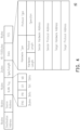
- FIG. 4 illustrates a schematic diagram of a packet format 40 (e.g., standard Ethernet frame) according to an embodiment of the disclosure.
- a packet format 40 e.g., standard Ethernet frame
- the controller 110 may pack the first data packet based on the packet format 40 to generate the second data packet.
- the packet format 40 may include a destination address field, a source address field, a VLAN tag field (e.g., 802.1Q tag field), an type/length value field (e.g., an Ether-type/length value field), a data field (or payload field), and a frame check sequence (FCS) field.
- the destination address field may store a destination address such as the MAC address of the target device.
- the destination address field of the second data packet may store the MAC address of the device 44.
- the source address field may store a source address such as the MAC address of the source device.
- the sources address field of the second data packet may store the MAC address of the gateway 41.
- the VLAN tag field may store a tag protocol identifier (TPID), a priority (PRI), a canonical format indicator (CFI), or a VLAN ID (i.e., VID).
- the controller 110 may generate the second data packet by modifying the VLAN tag field of the first data packet to record VLAN ID 11.
- the type/length value field may store type of data packet.
- the type/length value field may store "0x0806" if the packet format 40 is corresponding to an address resolution protocol (ARP) data packet.
- the data field may store a sender hardware address (e.g., MAC address of the source device), a sender protocol address (e.g., IP address of the source device), a target hardware address (e.g., MAC address of the target device), or a target protocol address (e.g., IP address of the target device).
- ARP address resolution protocol
- the data field of the second data packet may include the MAC address of the gateway 41 as the sender hardware address, the IP address of the gateway 41 as the sender protocol address, the MAC address of the device 44 as the target hardware address, and the IP address of the device 44 as the target protocol address.
- the target protocol address may be blanked.
- the target protocol address of an ARP query may be blanked and the Destination address of the ARP query may be a broadcast address (e.g., 0xFF).
- the FCS field may store an FCS value corresponding to the data field. The FCS value may be calculated according to the data field. If the data in the data field is changed, the FCS value may be changed accordingly.
- the controller 110 may modify the data field of the first data packet to include VLAN ID 11. That is, the FCS value of the second data packet should be different from the FCS value of the first data packet.
- the controller 110 may calculate the FCS value of the second data packet according to the modified data field.
- the PLD 200 may determine whether the second data packet is an address query packet (or a ARP packet) or not, wherein the address query packet may be, for example, an ARP query.
- the data field of the second data packet may further store an ARP indicator (e.g., Ether-type "0x0806") in the operation field.
- the ARP indicator may indicate that whether the second data packet is an address query packet or not.
- the PLD 200 may determine whether the second data packet is address query packet (or ARP packet) or not according to the operation field of the second data packet. If the second data packet is an address query packet, proceed to step S308. If the second data packet is not an address query packet (or ARP packet), proceed to step S304.
- the PLD 200 may filter the second data packet and determine whether the second data packet is matched with a mapping table. If the second data packet is matched with the mapping table, proceed to step S306. If the second data packet is not matched with the mapping table, proceed to step S305.
- the PLD 200 may filter the second data packet according to the first filtering rule.
- the first filtering rule may be associated with a TCP/UDP port number or a transmission protocol.
- the filtering rule may include the mapping table, wherein the mapping table may include a mapping relationship between a MAC address and a VLAN ID. In one embodiment, the mapping table may further include an IP address corresponding to the MAC address and the VLAN ID.
- the PLD 200 may determine that the second data packet is matched with the mapping table in response to a mapping relationship between the destination address of the second data packet and the VLAN ID of the second data packet being recorded in the mapping table.
- the PLD 200 may determine that the second data packet is not matched with the mapping table in response to the mapping relationship between the destination address of the second data packet and the VLAN ID of the second data packet not being recorded in the mapping table.
- Table 2 is an example of the mapping table stored in the PLD 200, the mapping table may record a mapping relationship between the MAC address of the gateway 41 and the VLAN ID 11. Assuming the data field of the second data packet stores the VLAN ID 11.
- the PLD 200 may determine that the second data packet is matched with the mapping table if the source address of the second data packet is the MAC address of the gateway 41, and the PLD 200 may determine that the second data packet is not matched with the mapping table if the source address of the second data packet is not the MAC address of the gateway 41.
- Table 2 MAC address IP address VLAN ID MAC address of gateway 41 IP address of gateway 41 VLAN ID 11 MAC address of gateway 42 IP address of gateway 42 VLAN ID 12 MAC address of device 43 IP address of device 43 VLAN ID 13 MAC address of device 44 IP address of device 44 VLAN ID 14 MAC address of device 45 IP address of device 45 VLAN ID 15
- the PLD 200 may drop the second data packet or may transmit the second data packet to the storage device 61 for further analysis.
- the PLD 200 may overwrite the first VLAN ID of the second data packet by a second VLAN ID corresponding to a second path so as to generate a third data packet, wherein the second VLAN ID may be corresponded to the path between the PLD 200 and the target device. That is, the PLD 200 may select the second VLAN ID from the mapping table according to the destination address of the second data packet. For example, the PLD 200 may overwrite the VLAN ID 11 in the second data packet by the VLAN ID 14 to generate the third data packet, wherein the VLAN ID 14 may be corresponded to the path 14 between the PLD 200 and the device 44 (i.e., target device).
- the PLD 200 may recalculate an FCS value for the third data packet according to the updated data field. In other words, the PLD 200 may update the FCS value of the second data packet to generate the third data packet.
- the PLD 200 may transmit the third data packet to the target device.
- the PLD 200 may transmit the third data packet to the device 44 via the port P7, the path 14, and the port P4.
- the PLD 200 may determine whether the second data packet is matched with a mapping table. If the second data packet is matched with the mapping table, proceed to step S312. If the second data packet is not matched with the mapping table, proceed to step S309. Specifically, the PLD 200 may store a mapping table, wherein the mapping table may include a mapping relationship among a MAC address, an IP address, and a VLAN ID. If the second data packet is an address query packet, the sender hardware address, the sender protocol address, and the target protocol address of the second data packet may be filled in by the source device, and the source device may leave the target hardware address of the second data packet blank. In other words, the MAC address of the target device is unknown to the second data packet.
- the PLD 200 may check whether a mapping relationship between the IP address of the target device and a MAC address is recorded in the mapping table.
- the PLD 200 may determine that the second data packet is matched with the mapping table in response to a mapping relationship between the IP address of the target device and a MAC address being recorded in the mapping table, and the PLD 200 may determine that the second data packet is not matched with the mapping table in response to the mapping relationship between the IP address of the target device and a MAC address not being recorded in the mapping table.
- Table 3 is an example of the mapping table stored in the PLD 200.
- the mapping table may be added in response to a data packet being received by the PLD 200.
- the IP address, VLAN ID and MAC address can be recorded into the mapping table.
- a network device may issue a broadcast packet (e.g., ARP response) to the intranet devices (e.g., devices coupled to the switch 100) so as to inform the intranet devices the hardware address and the software address of the network device.
- the PLD 200 may add a mapping relationship between the IP address of the network device and the MAC address of the network device to the mapping table.
- the second data packet transmitted from the gateway 41 to the PLD 200 may include a MAC address of the gateway 41, an IP address of the gateway 41, and an IP address of a target device.
- the PLD 200 may determine whether a mapping relationship between the IP address of the target device and a MAC address is recorded in Table 3. Since a mapping relationship between the IP address of the target device and the MAC address of the device 44 is recorded in Table 3, the PLD 200 may determine that the IP address of the target device is corresponded to the device 44. Accordingly, the PLD 200 may determine that the second data packet is matched with the mapping table.
- Table 3 MAC address IP address VLAN ID MAC address of gateway 41 IP address of gateway 41 VLAN ID 11 MAC address of device 44 IP address of target device VLAN ID 14
- Table 4 is an example of the mapping table stored in the PLD 200.
- the second data packet transmitted from the gateway 41 to the PLD 200 may include a MAC address of the gateway 41, an IP address of the gateway 41, and an IP address of a target device.
- the PLD 200 may determine whether a mapping relationship between the IP address of the target device and a MAC address is recorded in Table 4. Since no mapping relationship between the IP address of the target device and a MAC address is recorded in Table 4, the PLD 200 may determine that the second data packet is not matched with the mapping table.
- the PLD 200 may broadcast the IP address of the target device to one or more external device coupled to the switch 100.
- the PLD 200 may duplicate the second data packet to generate a plurality of broadcast data packets, wherein each of the broadcast data packets may include an IP address of the target device and a dedicated VLAN ID. That is, different broadcast data packet may have different VLAN ID.
- the PLD 200 may generate a broadcast data packet according to the second data packet and transmit the broadcast data packet to the device 44 via the port P4, wherein the broadcast data packet may include the IP address of the target device and the VLAN ID 14.
- the PLD 200 may generate a broadcast data packet according to the second data packet and transmit the broadcast data packet to the device 43 via the port P3, wherein the broadcast data packet may include the IP address of the target device and the VLAN ID 13.
- the PLD 200 may generate a broadcast data packet according to the second data packet and transmit the broadcast data packet to the gateway 42 via the port P2, wherein the broadcast data packet may include the IP address of the target device and the VLAN ID 12.
- the PLD 200 may generate a broadcast data packet according to the second data packet and transmit the broadcast data packet to the device 45 via the port P5, wherein the broadcast data packet may include the IP address of the target device and the VLAN ID 15.
- the PLD 200 may receive a MAC address from a target device (i.e., device 44) in response to broadcasting the IP address of the target device, and the PLD 200 may generate a response packet corresponding to the second data packet (i.e., address query packet), wherein the target device is one of the one or more external device receiving the broadcast data packet.
- the target device is one of the one or more external device receiving the broadcast data packet.
- the device 44 may transmit the MAC address of the device 44 to the PLD 200 via the port P4, the path 14, and the port P7 in response to receiving the broadcast data packet.
- the PLD 200 may set the source address of the response packet to the received MAC address. For example, the PLD 200 may set the source address of the response packet to the MAC address of the device 44. In addition, the PLD 200 may set the destination address of the response packet to the source address of the second data packet.
- the second data packet may include the MAC address of the gateway 41 as the source address.
- the PLD 200 may set the destination address of the response packet to the MAC address of the gateway 41.
- the PLD 200 may set the target hardware address of the response packet to the received MAC address, wherein the target hardware address is included in the data field of the response packet, and the target hardware address is the information which has not been filled in the second data packet. For example, the PLD 200 may set the target hardware address of the response packet to the MAC address of the device 44, wherein the MAC address of the device 44 has not been stored in the second data packet.
- the PLD 200 may add a mapping relationship between the IP address of the target device and the MAC address of the target device to the mapping table. For example, assuming that the mapping table stored in the PLD 200 presently is Table 4.
- the PLD 200 may determine that the IP address of the target device is corresponded to the MAC address of the device 44. Thus, the PLD 200 may add a relationship between the IP address of the target device and the MAC address of the device 44 to Table 4. Accordingly, Table 4 may be modified to Table 3 by the PLD 200.
- the PLD 200 may transmit the response packet to the source device (i.e., gateway 41), wherein the response packet may be an ARP response corresponding to the ARP query. Specifically, the PLD 200 may transmit the response packet to the gateway 41 via the port P7, the path 11, and the port P1.
- the source device i.e., gateway 41
- the response packet may be an ARP response corresponding to the ARP query.
- the PLD 200 may transmit the response packet to the gateway 41 via the port P7, the path 11, and the port P1.
- the PLD 200 may generate a response packet corresponding to the second data packet (i.e., address query packet) according to the mapping table. Specifically, the PLD 200 may set the source address of the response packet to the MAC address associated with the IP address of the target device. Taking Table 3 as an example, in response to the mapping relationship between the IP address of the target device and the MAC address of the device 44 being recorded in Table 3, the PLD 200 may determine that the IP address of the target device is associated with the MAC address of the device 44. Thus, the PLD 200 may set the source address of the response packet to the MAC address of the device 44 according to the mapping table.
- the IP address of the target device may not need to be broadcasted to the actual target device (i.e., device 44) so as to obtain the MAC address of the target device.
- the PLD 200 may generate an ARP response corresponding to the ARP query based on an established mapping table. The step of duplicating the ARP query or broadcasting the ARP query can be omitted. Therefore, the source device may obtain the IP address of the target device in a shorter time.
- the PLD 200 may set the destination address of the response packet to the source address of the second data packet.
- the second data packet may include the MAC address of the gateway 41 as the source address.
- the PLD 200 may set the destination address of the response packet to the MAC address of the gateway 41.
- the PLD 200 may set the target hardware address of the response packet to the MAC address associated with the IP address of the target device, wherein the target hardware address is included in the data field of the response packet, and the target hardware address is the information which has not been filled in the second data packet.
- the PLD 200 may determine that the MAC address of the device 44 is associated with the IP address of the target device.
- the PLD 200 may set the target hardware address of the response packet to the MAC address of the device 44.
- FIG. 5 illustrates a flowchart of a communication method for one-way transmission based on VLAN ID according to an embodiment of the disclosure, wherein the communication method may be implemented by the switch device 10 as shown in FIG. 1 .
- step S501 coupling a first port of a switch and a third port of the switch via a first path, coupling a second port of the switch and the third port via a second path, and coupling a first programmable logic device and the third port.
- step S502 receiving, by the first port, a first data packet from a first external device.
- step S503 packing the first data packet with a first virtual local area network identifier corresponding to the first path to generate a second data packet.
- step S504 receiving, by the first programmable logic device, the second data packet from the third port.
- step S505 filtering, by the first programmable logic device, the second data packet according to a first filtering rule.
- step S506 in response to the second data packet being matched with the first filtering rule, overwriting the first virtual local area network identifier by a second virtual local area network identifier corresponding to the second path to generate a third data packet.
- step S507 transmitting, by the first programmable logic device, the third data packet to the second port via the second path so as to output the third data packet via the second port.
- the present disclosure may decrease the delay of the one-way transmission between the secure site and the unsecure site by configuring a switch device instead of a high-end computer to connect the secure site and the unsecure site.
- the switch device may not need to retrieve all the content (e.g., each layer of the communication protocol stack of the data packet) of the data packet when forwarding the data packet with a predefined protocol.
- the switch device may include a PLD which may filter data packets for the transmission between the devices in the secure site. Before forwarding the filtered data packet to the destination, the PLD may update the VLAN ID of the data packet so as to prevent the data packet from violating the rules defined by the address table of the switch.
- the PLD may establish or update a mapping table (e.g., ARP table) including a mapping relation between an IP address and a MAC address of a target device. If a source device transmits an ARP query to the target device, the PLD may reply an ARP response to the source device for the target device. Thus, the ARP query may not need to forward to the target device and the source device may get the MAC address of the target device in a shorter time.
- a mapping table e.g., ARP table
Landscapes
- Engineering & Computer Science (AREA)
- Computer Networks & Wireless Communication (AREA)
- Signal Processing (AREA)
- Computer Security & Cryptography (AREA)
- Small-Scale Networks (AREA)
- Data Exchanges In Wide-Area Networks (AREA)
- Mobile Radio Communication Systems (AREA)
- Near-Field Transmission Systems (AREA)
- Transceivers (AREA)
Claims (8)
- Schaltvorrichtung (10) für eine einseitige Übertragung auf der Grundlage einer Kennung für ein virtuelles lokales Netzwerk; wobei die Schaltvorrichtung (10) umfasst:einen Switch (100), umfassend:einen ersten Port (P1);einen zweiten Port (P4);einen dritten Port (P7), der so konfiguriert ist, dass er über einen ersten Pfad (11) mit dem ersten Port und über einen zweiten Pfad (14) mit dem zweiten Port gekoppelt ist; undeine Steuerung (110), die mit dem ersten Port (P1), dem zweiten Port (P4) und dem dritten Port (P7) gekoppelt ist; und wobei die Schaltvorrichtung (10) weiterhin umfassteine erste programmierbare Logikvorrichtung (200), die mit dem dritten Port (P7) gekoppelt ist, wobeider erste Port (P1) so konfiguriert ist, dass er ein erstes Datenpaket von einem ersten externen Gerät (41) empfängt;die Steuerung (110) so konfiguriert ist, dass diese das erste Datenpaket mit einer ersten Kennung für ein virtuelles lokales Netzwerk packt, die dem ersten Pfad (11) entspricht, um ein zweites Datenpaket zu erzeugen;die erste programmierbare Logikvorrichtung (200) ist so konfiguriert, dass diese eine Zuordnungstabelle speichert, das zweite Datenpaket von dem dritten Port (P7) empfängt und das zweite Datenpaket gemäß einer ersten Filterregel filtert;die erste programmierbare Logikvorrichtung (200) so konfiguriert ist, dass diese in Reaktion darauf, dass das zweite Datenpaket der ersten Filterregel entspricht, die erste Kennung für das virtuelle lokale Netzwerk durch eine zweite Kennung für das virtuelle lokale Netzwerk, die dem zweiten Pfad (14) entspricht, überschreibt, um ein drittes Datenpaket zu erzeugen; unddie erste programmierbare Logikvorrichtung (200) so konfiguriert ist, dass diese das dritte Datenpaket über den zweiten Pfad (14) an den zweiten Port (P4) überträgt, um das dritte Datenpaket über den zweiten Port (P4) auszugeben; wobeider erste Port (P1) so konfiguriert ist, dass er ein Adressabfragepaket von der ersten externen Vorrichtung (41) empfängt und das Adressabfragepaket an den dritten Port (P7) überträgt, wobei das Adressabfragepaket eine Internetprotokoll-IP-Adresse umfasst;die erste programmierbare Logikvorrichtung (200) so konfiguriert ist, dass diese das Adressabfragepaket von dem dritten Port (P7) empfängt und die IP-Adresse über den zweiten Port (P4) an eine zweite externe Vorrichtung (44) sendet;die erste programmierbare Logikvorrichtung (200) so konfiguriert ist, dass diese als Reaktion auf das Rundsenden der IP-Adresse eine MAC-Adresse (Media Access Control) von der zweiten externen Vorrichtung (44) über den zweiten Port (P4) empfängt und als Reaktion auf den Empfang der MAC-Adresse von der zweiten externen Vorrichtung (44) eine Abbildungsbeziehung zwischen der IP-Adresse und der MAC-Adresse in die Zuordnungstabelle einfügt; unddie erste programmierbare Logikvorrichtung (200) so konfiguriert ist, dass diese ein Antwortpaket erzeugt, das dem Adressabfragepaket entspricht, indem sie eine Quelladresse des Antwortpakets auf die MAC-Adresse setzt.
- Schaltvorrichtung (10) nach Anspruch 1, wobei das zweite Datenpaket eine Zieladresse umfasst, wobei
die erste programmierbare Logikvorrichtung (200) so konfiguriert ist, dass diese die erste Kennung für das virtuelle lokale Netzwerk durch die zweite Kennung für das virtuelle lokale Netzwerk überschreibt, wenn eine zweite Abbildungsbeziehung zwischen der Zieladresse und der zweiten Kennung für das virtuelle lokale Netzwerk in der Zuordnungstabelle gespeichert ist. - Schaltvorrichtung (10) nach Anspruch 2, wobei die erste programmierbare Logikvorrichtung (200) so konfiguriert ist, dass diese das zweite Datenpaket als Reaktion darauf verwirft, dass die zweite Abbildungsbeziehung zwischen der Zieladresse und der Kennung für das zweite virtuelle lokale Netzwerk nicht in der Zuordnungstabelle gespeichert ist.
- Schaltvorrichtung (10) nach Anspruch 2, wobei das zweite Datenpaket ferner eine Rahmenprüfsequenz umfasst, wobei die erste programmierbare Logikvorrichtung (200) so konfiguriert ist, dass diese die Rahmenprüfsequenz aktualisiert, um das dritte Datenpaket als Reaktion auf das Überschreiben der ersten Kennung für das virtuelle lokale Netzwerk durch die zweite Kennung für das virtuelle lokale Netzwerk zu erzeugen.
- Schaltvorrichtung (10) nach Anspruch 1, wobei
die erste programmierbare Logikvorrichtung (200) so konfiguriert ist, dass diese das Antwortpaket über den dritten Port (P7) an den ersten Port (P1) sendet. - Schaltvorrichtung (10) nach Anspruch 5, wobei die erste programmierbare Logikvorrichtung (200) so konfiguriert ist, dass diese das Antwortpaket ferner erzeugt durch
Einstellen einer Zielhardwareadresse des Antwortpakets auf die MAC-Adresse. - Schaltvorrichtung (10) nach Anspruch 1, wobei die erste Filterregel mindestens einer Portnummer oder einem Übertragungsprotokoll entspricht, wobei das Übertragungsprotokoll eines der folgenden Protokolle umfasst: ein Modbus-Protokoll, ein IEC 60870-5-104-Protokoll, ein verteiltes Netzwerkprotokoll und ein speicherprogrammierbares Steuerungsprotokoll.
- Kommunikationsverfahren, das von einer Schaltvorrichtung (10) für eine einseitige Übertragung auf der Grundlage einer Kennung für ein virtuelles lokales Netzwerk durchgeführt wird, mit den Schritten:Koppeln eines ersten Ports eines Switches der Schaltvorrichtung (10) und eines dritten Ports des Switches über einen ersten Pfad, Koppeln eines zweiten Ports des Switches und des dritten Ports über einen zweiten Pfad, und Koppeln einer ersten programmierbaren Logikvorrichtung der Schaltvorrichtung und des dritten Ports (S501);Empfangen eines ersten Datenpakets von einer ersten externen Vorrichtung über den ersten Port (S502);Packen des ersten Datenpakets mit einer ersten Kennung für das virtuelle lokale Netzwerk, die dem ersten Pfad entspricht, um ein zweites Datenpaket zu erzeugen (S503);Speichern einer Zuordnungstabelle durch die erste programmierbare Logikvorrichtung;Empfangen des zweiten Datenpakets durch die erste programmierbare Logikvorrichtung von dem dritten Port (S504);Filtern des zweiten Datenpakets durch die erste programmierbare Logikvorrichtung gemäß einer ersten Filterregel (S505);als Reaktion darauf, dass das zweite Datenpaket der ersten Filterregel entspricht, Überschreiben der ersten Kennung für das virtuelle lokale Netzwerk durch eine zweite Kennung für das virtuelle lokale Netzwerk, die dem zweiten Pfad entspricht, um ein drittes Datenpaket zu erzeugen (S506); undÜbertragen des dritten Datenpakets durch die erste programmierbare Logikvorrichtung an den zweiten Port über den zweiten Pfad, um das dritte Datenpaket über den zweiten Port auszugeben (S507);Empfangen eines Adressabfragepakets von der ersten externen Vorrichtung durch den ersten Port und Übertragen des Adressabfragepakets an den dritten Port, wobei das Adressabfragepaket eine Internetprotokoll-IP-Adresse umfasst;Empfangen des Adressabfragepakets von dem dritten Port durch die erste programmierbare Logikvorrichtung und Rundsenden der IP-Adresse an eine zweite externe Vorrichtung über den zweiten Port durch die erste programmierbare Logikvorrichtung;Empfangen, durch die erste programmierbare Logikvorrichtung, einer MAC-Adresse (Media Access Control) von der zweiten externen Vorrichtung über den zweiten Port als Reaktion auf das Rundsenden der IP-Adresse;Hinzufügen einer ersten Abbildungsbeziehung zwischen der IP-Adresse und der MAC-Adresse durch die erste programmierbare Logikvorrichtung in Reaktion auf den Empfang der MAC-Adresse von der zweiten externen Vorrichtung; undErzeugen, durch die erste programmierbare Logikvorrichtung, eines Antwortpakets, das dem Adressabfragepaket entspricht, indem eine Quelladresse des Antwortpakets auf die MAC-Adresse gesetzt wird.
Priority Applications (1)
| Application Number | Priority Date | Filing Date | Title |
|---|---|---|---|
| DE21174924.7T DE21174924T1 (de) | 2021-01-15 | 2021-05-20 | Kommunikationsverfahren für Einweg-Übertragung basierend auf VLAN-ID und Switch-Gerät, das dieselben verwendet |
Applications Claiming Priority (2)
| Application Number | Priority Date | Filing Date | Title |
|---|---|---|---|
| US202163137761P | 2021-01-15 | 2021-01-15 | |
| US17/306,871 US11477048B2 (en) | 2021-01-15 | 2021-05-03 | Communication method for one-way transmission based on VLAN ID and switch device using the same |
Publications (2)
| Publication Number | Publication Date |
|---|---|
| EP4030701A1 EP4030701A1 (de) | 2022-07-20 |
| EP4030701B1 true EP4030701B1 (de) | 2024-10-30 |
Family
ID=76034496
Family Applications (1)
| Application Number | Title | Priority Date | Filing Date |
|---|---|---|---|
| EP21174924.7A Active EP4030701B1 (de) | 2021-01-15 | 2021-05-20 | Kommunikationsverfahren für unidirektionale übertragung auf basis von vlan-id und schaltvorrichtung mit verwendung davon |
Country Status (7)
| Country | Link |
|---|---|
| US (1) | US11477048B2 (de) |
| EP (1) | EP4030701B1 (de) |
| JP (1) | JP2022109857A (de) |
| KR (1) | KR20220103603A (de) |
| CA (1) | CA3122556A1 (de) |
| DE (1) | DE21174924T1 (de) |
| ES (1) | ES2921923T1 (de) |
Families Citing this family (5)
| Publication number | Priority date | Publication date | Assignee | Title |
|---|---|---|---|---|
| US11477048B2 (en) * | 2021-01-15 | 2022-10-18 | BlackBear (Taiwan) Industrial Networking Security Ltd. | Communication method for one-way transmission based on VLAN ID and switch device using the same |
| US11812520B2 (en) * | 2021-09-27 | 2023-11-07 | Versa Networks, Inc. | Methods and systems for providing network connectivity to a secure access service edge (SASE) domain |
| CN115866038B (zh) * | 2022-11-28 | 2024-12-06 | 成都知道创宇信息技术有限公司 | 透明代理方法、装置、电子设备及计算机可读存储介质 |
| CN116506372B (zh) * | 2023-04-28 | 2025-12-02 | 新华三技术有限公司 | 一种报文转发方法及设备 |
| US12615257B2 (en) | 2024-02-29 | 2026-04-28 | Versa Networks, Inc. | Methods and systems for providing network connectivity to a secure access service edge (SASE) domain via an ISP |
Family Cites Families (50)
| Publication number | Priority date | Publication date | Assignee | Title |
|---|---|---|---|---|
| US5703562A (en) | 1996-11-20 | 1997-12-30 | Sandia Corporation | Method for transferring data from an unsecured computer to a secured computer |
| EP1162798A3 (de) * | 2000-06-09 | 2007-12-26 | Broadcom Corporation | Paketweiterleitung zwischen mehrere Gigabit-Vermittlungseinheiten verschidener Arten |
| US7120150B2 (en) * | 2001-01-30 | 2006-10-10 | At & T Corp. | Technique for ethernet access to packet-based services |
| US7362797B2 (en) * | 2002-03-21 | 2008-04-22 | Broadcom Corporation | Physical layer device having an analog SERDES pass through mode |
| ATE480925T1 (de) | 2002-10-04 | 2010-09-15 | Ericsson Telefon Ab L M | Isolation von mit einem zugangsnetzwerk verbundenen hosts |
| WO2004105297A2 (en) | 2003-05-19 | 2004-12-02 | Network Security Technologies, Inc. | Method and system for providing secure one-way transfer of data |
| US7698412B2 (en) * | 2003-12-31 | 2010-04-13 | Alcatel Lucent | Parallel data link layer controllers in a network switching device |
| CN100461732C (zh) | 2006-06-16 | 2009-02-11 | 华为技术有限公司 | 一种以太技术交换和转发的方法、系统和设备 |
| HUE030535T2 (en) | 2006-06-27 | 2017-05-29 | Waterfall Security Solutions Ltd | One-way security connections from a security operating unit to a security operating unit |
| JP2008022075A (ja) * | 2006-07-10 | 2008-01-31 | Yamaha Corp | レイヤ2スイッチおよびネットワーク監視システム |
| US8116320B2 (en) * | 2006-08-07 | 2012-02-14 | Adc Telecommunications, Inc. | Mapping external port using virtual local area network |
| IL189514A (en) * | 2007-02-14 | 2011-12-29 | Marvell Israel Misl Ltd | Logical bridging system and method |
| US8352450B1 (en) | 2007-04-19 | 2013-01-08 | Owl Computing Technologies, Inc. | Database update through a one-way data link |
| US7649452B2 (en) | 2007-06-29 | 2010-01-19 | Waterfall Solutions Ltd. | Protection of control networks using a one-way link |
| US7992209B1 (en) | 2007-07-19 | 2011-08-02 | Owl Computing Technologies, Inc. | Bilateral communication using multiple one-way data links |
| US8250358B2 (en) | 2009-04-01 | 2012-08-21 | Raytheon Company | Data diode system |
| US9521120B2 (en) | 2009-04-23 | 2016-12-13 | General Electric Technology Gmbh | Method for securely transmitting control data from a secure network |
| DE102010011022A1 (de) | 2010-03-11 | 2012-02-16 | Siemens Aktiengesellschaft | Verfahren zur sicheren unidirektionalen Übertragung von Signalen |
| GB2495018B (en) | 2010-07-19 | 2017-02-22 | Owl Computing Tech Inc | Secure acknowledgment device for one-way data transfer system |
| US8660075B2 (en) | 2011-01-10 | 2014-02-25 | Brocade Communications Systems, Inc. | Congestion notification in private VLANs |
| TWI583151B (zh) * | 2011-08-04 | 2017-05-11 | 中界雲端公司 | 實施及管理虛擬網路的系統與方法 |
| CN102316030B (zh) * | 2011-09-01 | 2014-04-09 | 杭州华三通信技术有限公司 | 一种实现数据中心二层互联的方法和装置 |
| US9590820B1 (en) * | 2011-09-02 | 2017-03-07 | Juniper Networks, Inc. | Methods and apparatus for improving load balancing in overlay networks |
| US8893253B2 (en) | 2011-11-29 | 2014-11-18 | Bayshore Networks, Inc. | Firewall apparatus, systems, and methods employing detection of application anomalies |
| US9736121B2 (en) | 2012-07-16 | 2017-08-15 | Owl Cyber Defense Solutions, Llc | File manifest filter for unidirectional transfer of files |
| US8514828B1 (en) * | 2012-10-30 | 2013-08-20 | Aruba Networks, Inc. | Home virtual local area network identification for roaming mobile clients |
| US8875256B2 (en) * | 2012-11-13 | 2014-10-28 | Advanced Micro Devices, Inc. | Data flow processing in a network environment |
| US8776254B1 (en) | 2013-01-23 | 2014-07-08 | Owl Computing Technologies, Inc. | System and method for the secure unidirectional transfer of software and software updates |
| US9306953B2 (en) | 2013-02-19 | 2016-04-05 | Owl Computing Technologies, Inc. | System and method for secure unidirectional transfer of commands to control equipment |
| US9419975B2 (en) | 2013-04-22 | 2016-08-16 | Waterfall Security Solutions Ltd. | Bi-directional communication over a one-way link |
| US20150030027A1 (en) * | 2013-07-26 | 2015-01-29 | Lsi Corporation | Switch Device With Device-Specified Bridge Domains |
| US9088558B2 (en) | 2013-08-21 | 2015-07-21 | Owl Computing Technologies, Inc. | Secure one-way interface for OPC data transfer |
| US20150085868A1 (en) * | 2013-09-25 | 2015-03-26 | Cavium, Inc. | Semiconductor with Virtualized Computation and Switch Resources |
| US9531669B2 (en) | 2014-01-30 | 2016-12-27 | Sierra Nevada Corporation | Bi-directional data security for supervisor control and data acquisition networks |
| US20150236911A1 (en) * | 2014-02-18 | 2015-08-20 | Aruba Networks, Inc. | Detecting characteristics of a data path loop on a network |
| US20150236946A1 (en) * | 2014-02-18 | 2015-08-20 | Aruba Networks, Inc. | Operating on a network with characteristics of a data path loop |
| US8891546B1 (en) | 2014-04-27 | 2014-11-18 | Waterfall Security Solutions Ltd. | Protocol splitter |
| GB201410089D0 (en) | 2014-06-06 | 2014-07-23 | Bae Systems Plc | Secured network bridge |
| US10015023B2 (en) | 2014-09-08 | 2018-07-03 | Quanta Computer Inc. | High-bandwidth chassis and rack management by VLAN |
| KR101593168B1 (ko) | 2014-09-11 | 2016-02-18 | 한국전자통신연구원 | 물리적 단방향 통신 장치 및 방법 |
| US10931478B2 (en) * | 2014-10-14 | 2021-02-23 | Mido Holdings Ltd. | System and method for distributed flow state P2P setup in virtual networks |
| DE102014226398A1 (de) | 2014-12-18 | 2016-06-23 | Siemens Aktiengesellschaft | Verfahren und Vorrichtung zum rückwirkungsfreien Erfassen von Daten |
| US9853918B2 (en) | 2015-03-24 | 2017-12-26 | Owl Cyber Defense Solutions, Llc | One-way network interface |
| US9860160B2 (en) * | 2015-12-30 | 2018-01-02 | Stmicroelectronics, Inc. | Multipath switching using per-hop virtual local area network classification |
| ES2778848T3 (es) | 2017-07-05 | 2020-08-12 | Siemens Mobility GmbH | Procedimiento y dispositivo para la transmisión unidireccional sin repercusión de datos a un servidor de aplicación remoto |
| DE102017217432A1 (de) | 2017-09-29 | 2019-04-04 | Siemens Mobility GmbH | Konzept zum unidirektionalen Übertragen von Daten |
| US11336508B2 (en) * | 2018-07-01 | 2022-05-17 | Mellanox Technologies, Ltd. | Transparent failover in a network interface controller |
| IL268485B (en) | 2018-08-13 | 2022-04-01 | Waterfall Security Solutions Ltd | Automatic security response using one-way links |
| US10990737B2 (en) | 2019-04-23 | 2021-04-27 | Owl Cyber Defense Solutions, Llc | Secure one-way network gateway |
| US11477048B2 (en) * | 2021-01-15 | 2022-10-18 | BlackBear (Taiwan) Industrial Networking Security Ltd. | Communication method for one-way transmission based on VLAN ID and switch device using the same |
-
2021
- 2021-05-03 US US17/306,871 patent/US11477048B2/en active Active
- 2021-05-20 ES ES21174924T patent/ES2921923T1/es active Pending
- 2021-05-20 DE DE21174924.7T patent/DE21174924T1/de active Pending
- 2021-05-20 EP EP21174924.7A patent/EP4030701B1/de active Active
- 2021-06-17 CA CA3122556A patent/CA3122556A1/en active Pending
- 2021-06-23 KR KR1020210081646A patent/KR20220103603A/ko active Pending
- 2021-08-02 JP JP2021126754A patent/JP2022109857A/ja active Pending
Also Published As
| Publication number | Publication date |
|---|---|
| EP4030701A1 (de) | 2022-07-20 |
| KR20220103603A (ko) | 2022-07-22 |
| US20220231881A1 (en) | 2022-07-21 |
| DE21174924T1 (de) | 2022-09-08 |
| CA3122556A1 (en) | 2022-07-15 |
| US11477048B2 (en) | 2022-10-18 |
| ES2921923T1 (es) | 2022-09-02 |
| JP2022109857A (ja) | 2022-07-28 |
Similar Documents
| Publication | Publication Date | Title |
|---|---|---|
| US11477048B2 (en) | Communication method for one-way transmission based on VLAN ID and switch device using the same | |
| US10050970B2 (en) | System and method for data center security enhancements leveraging server SOCs or server fabrics | |
| US10148459B2 (en) | Network service insertion | |
| US9414136B2 (en) | Methods and apparatus to route fibre channel frames using reduced forwarding state on an FCoE-to-FC gateway | |
| US6856621B1 (en) | Method of transmission of data in cluster environment | |
| CN113132342A (zh) | 方法、网络装置、隧道入口点装置及存储介质 | |
| CN100414532C (zh) | 用于通信流量的选择性转移和注入的方法和装置 | |
| US11489752B2 (en) | Forwarding entry monitoring method and apparatus | |
| KR102621953B1 (ko) | 패킷 검출 방법 및 제1 네트워크 장치 | |
| JP7119170B2 (ja) | Bierv6パケット転送方法、デバイス、およびシステム | |
| CN116566752A (zh) | 安全引流系统、云主机及安全引流方法 | |
| US8675669B2 (en) | Policy homomorphic network extension | |
| US20200228496A1 (en) | Transfer apparatus | |
| US20060256717A1 (en) | Electronic packet control system | |
| US20060256770A1 (en) | Interface for configuring ad hoc network packet control | |
| Aweya | Switch/router architectures: systems with crossbar switch fabrics | |
| Gross et al. | RFC 8926: Geneve: Generic Network Virtualization Encapsulation | |
| TWI773394B (zh) | 用於基於vlan id的單向傳輸的通訊方法及使用其的交換器裝置 | |
| US11502872B1 (en) | Isolation of clients within a virtual local area network (VLAN) in a fabric network | |
| US12542734B2 (en) | Efficient multicast forwarding by shared gateway switch in multi-fabric network | |
| US8561166B2 (en) | Efficient implementation of security applications in a networked environment | |
| CN121907544A (zh) | 报文处理方式、报文处理装置、电子设备、介质及产品 | |
| WO2026020711A1 (zh) | 终端通信方法、装置、计算机设备和存储介质 | |
| Acton | Internet Protocols—Advances in Research and Application: 2013 Edition | |
| JP2008131466A (ja) | パケット中継装置 |
Legal Events
| Date | Code | Title | Description |
|---|---|---|---|
| PUAI | Public reference made under article 153(3) epc to a published international application that has entered the european phase |
Free format text: ORIGINAL CODE: 0009012 |
|
| STAA | Information on the status of an ep patent application or granted ep patent |
Free format text: STATUS: REQUEST FOR EXAMINATION WAS MADE |
|
| 17P | Request for examination filed |
Effective date: 20211216 |
|
| AK | Designated contracting states |
Kind code of ref document: A1 Designated state(s): AL AT BE BG CH CY CZ DE DK EE ES FI FR GB GR HR HU IE IS IT LI LT LU LV MC MK MT NL NO PL PT RO RS SE SI SK SM TR |
|
| REG | Reference to a national code |
Ref country code: ES Ref legal event code: BA2A Ref document number: 2921923 Country of ref document: ES Kind code of ref document: T1 Effective date: 20220902 |
|
| REG | Reference to a national code |
Ref country code: DE Ref legal event code: R210 Ref document number: 602021020870 Country of ref document: DE |
|
| STAA | Information on the status of an ep patent application or granted ep patent |
Free format text: STATUS: EXAMINATION IS IN PROGRESS |
|
| 17Q | First examination report despatched |
Effective date: 20230120 |
|
| GRAP | Despatch of communication of intention to grant a patent |
Free format text: ORIGINAL CODE: EPIDOSNIGR1 |
|
| STAA | Information on the status of an ep patent application or granted ep patent |
Free format text: STATUS: GRANT OF PATENT IS INTENDED |
|
| INTG | Intention to grant announced |
Effective date: 20240805 |
|
| RIC1 | Information provided on ipc code assigned before grant |
Ipc: H04L 49/00 20220101ALI20240729BHEP Ipc: H04L 12/46 20060101AFI20240729BHEP |
|
| RIN1 | Information on inventor provided before grant (corrected) |
Inventor name: HSU, PO-CHIH Inventor name: CHAN, YUAN CHEN |
|
| GRAS | Grant fee paid |
Free format text: ORIGINAL CODE: EPIDOSNIGR3 |
|
| GRAA | (expected) grant |
Free format text: ORIGINAL CODE: 0009210 |
|
| STAA | Information on the status of an ep patent application or granted ep patent |
Free format text: STATUS: THE PATENT HAS BEEN GRANTED |
|
| REG | Reference to a national code |
Ref country code: DE Ref legal event code: R081 Ref document number: 602021020870 Country of ref document: DE Owner name: BLACKBEAR (TAIWAN) INDUSTRIAL NETWORKING SECUR, TW Free format text: FORMER OWNER: BLACKBEAR (TAIWAN) INDUSTRIAL NETWORKING SECURITY LTD., JUBEI, HSINCHU, TW Ref country code: DE Ref legal event code: R082 Country of ref document: DE Ref document number: 602021020870 Representative=s name: BECKER KURIG & PARTNER PATENTANWAELTE MBB, DE |
|
| AK | Designated contracting states |
Kind code of ref document: B1 Designated state(s): AL AT BE BG CH CY CZ DE DK EE ES FI FR GB GR HR HU IE IS IT LI LT LU LV MC MK MT NL NO PL PT RO RS SE SI SK SM TR |
|
| REG | Reference to a national code |
Ref country code: GB Ref legal event code: FG4D |
|
| REG | Reference to a national code |
Ref country code: CH Ref legal event code: EP |
|
| REG | Reference to a national code |
Ref country code: DE Ref legal event code: R096 Ref document number: 602021020870 Country of ref document: DE |
|
| REG | Reference to a national code |
Ref country code: IE Ref legal event code: FG4D Ref country code: DE Ref legal event code: R082 Ref document number: 602021020870 Country of ref document: DE Representative=s name: BECKER KURIG & PARTNER PATENTANWAELTE MBB, DE |
|
| REG | Reference to a national code |
Ref country code: LT Ref legal event code: MG9D |
|
| REG | Reference to a national code |
Ref country code: NL Ref legal event code: MP Effective date: 20241030 |
|
| PG25 | Lapsed in a contracting state [announced via postgrant information from national office to epo] |
Ref country code: IS Free format text: LAPSE BECAUSE OF FAILURE TO SUBMIT A TRANSLATION OF THE DESCRIPTION OR TO PAY THE FEE WITHIN THE PRESCRIBED TIME-LIMIT Effective date: 20250228 Ref country code: PT Free format text: LAPSE BECAUSE OF FAILURE TO SUBMIT A TRANSLATION OF THE DESCRIPTION OR TO PAY THE FEE WITHIN THE PRESCRIBED TIME-LIMIT Effective date: 20250228 Ref country code: HR Free format text: LAPSE BECAUSE OF FAILURE TO SUBMIT A TRANSLATION OF THE DESCRIPTION OR TO PAY THE FEE WITHIN THE PRESCRIBED TIME-LIMIT Effective date: 20241030 |
|
| PG25 | Lapsed in a contracting state [announced via postgrant information from national office to epo] |
Ref country code: NL Free format text: LAPSE BECAUSE OF FAILURE TO SUBMIT A TRANSLATION OF THE DESCRIPTION OR TO PAY THE FEE WITHIN THE PRESCRIBED TIME-LIMIT Effective date: 20241030 Ref country code: FI Free format text: LAPSE BECAUSE OF FAILURE TO SUBMIT A TRANSLATION OF THE DESCRIPTION OR TO PAY THE FEE WITHIN THE PRESCRIBED TIME-LIMIT Effective date: 20241030 |
|
| REG | Reference to a national code |
Ref country code: AT Ref legal event code: MK05 Ref document number: 1738019 Country of ref document: AT Kind code of ref document: T Effective date: 20241030 |
|
| PG25 | Lapsed in a contracting state [announced via postgrant information from national office to epo] |
Ref country code: BG Free format text: LAPSE BECAUSE OF FAILURE TO SUBMIT A TRANSLATION OF THE DESCRIPTION OR TO PAY THE FEE WITHIN THE PRESCRIBED TIME-LIMIT Effective date: 20241030 |
|
| PG25 | Lapsed in a contracting state [announced via postgrant information from national office to epo] |
Ref country code: ES Free format text: LAPSE BECAUSE OF FAILURE TO SUBMIT A TRANSLATION OF THE DESCRIPTION OR TO PAY THE FEE WITHIN THE PRESCRIBED TIME-LIMIT Effective date: 20241030 |
|
| PG25 | Lapsed in a contracting state [announced via postgrant information from national office to epo] |
Ref country code: NO Free format text: LAPSE BECAUSE OF FAILURE TO SUBMIT A TRANSLATION OF THE DESCRIPTION OR TO PAY THE FEE WITHIN THE PRESCRIBED TIME-LIMIT Effective date: 20250130 |
|
| PG25 | Lapsed in a contracting state [announced via postgrant information from national office to epo] |
Ref country code: GR Free format text: LAPSE BECAUSE OF FAILURE TO SUBMIT A TRANSLATION OF THE DESCRIPTION OR TO PAY THE FEE WITHIN THE PRESCRIBED TIME-LIMIT Effective date: 20250131 Ref country code: LV Free format text: LAPSE BECAUSE OF FAILURE TO SUBMIT A TRANSLATION OF THE DESCRIPTION OR TO PAY THE FEE WITHIN THE PRESCRIBED TIME-LIMIT Effective date: 20241030 Ref country code: AT Free format text: LAPSE BECAUSE OF FAILURE TO SUBMIT A TRANSLATION OF THE DESCRIPTION OR TO PAY THE FEE WITHIN THE PRESCRIBED TIME-LIMIT Effective date: 20241030 |
|
| PG25 | Lapsed in a contracting state [announced via postgrant information from national office to epo] |
Ref country code: PL Free format text: LAPSE BECAUSE OF FAILURE TO SUBMIT A TRANSLATION OF THE DESCRIPTION OR TO PAY THE FEE WITHIN THE PRESCRIBED TIME-LIMIT Effective date: 20241030 |
|
| PG25 | Lapsed in a contracting state [announced via postgrant information from national office to epo] |
Ref country code: RS Free format text: LAPSE BECAUSE OF FAILURE TO SUBMIT A TRANSLATION OF THE DESCRIPTION OR TO PAY THE FEE WITHIN THE PRESCRIBED TIME-LIMIT Effective date: 20250130 |
|
| PG25 | Lapsed in a contracting state [announced via postgrant information from national office to epo] |
Ref country code: SM Free format text: LAPSE BECAUSE OF FAILURE TO SUBMIT A TRANSLATION OF THE DESCRIPTION OR TO PAY THE FEE WITHIN THE PRESCRIBED TIME-LIMIT Effective date: 20241030 |
|
| PG25 | Lapsed in a contracting state [announced via postgrant information from national office to epo] |
Ref country code: DK Free format text: LAPSE BECAUSE OF FAILURE TO SUBMIT A TRANSLATION OF THE DESCRIPTION OR TO PAY THE FEE WITHIN THE PRESCRIBED TIME-LIMIT Effective date: 20241030 |
|
| PG25 | Lapsed in a contracting state [announced via postgrant information from national office to epo] |
Ref country code: EE Free format text: LAPSE BECAUSE OF FAILURE TO SUBMIT A TRANSLATION OF THE DESCRIPTION OR TO PAY THE FEE WITHIN THE PRESCRIBED TIME-LIMIT Effective date: 20241030 |
|
| PG25 | Lapsed in a contracting state [announced via postgrant information from national office to epo] |
Ref country code: RO Free format text: LAPSE BECAUSE OF FAILURE TO SUBMIT A TRANSLATION OF THE DESCRIPTION OR TO PAY THE FEE WITHIN THE PRESCRIBED TIME-LIMIT Effective date: 20241030 |
|
| PG25 | Lapsed in a contracting state [announced via postgrant information from national office to epo] |
Ref country code: SK Free format text: LAPSE BECAUSE OF FAILURE TO SUBMIT A TRANSLATION OF THE DESCRIPTION OR TO PAY THE FEE WITHIN THE PRESCRIBED TIME-LIMIT Effective date: 20241030 |
|
| PG25 | Lapsed in a contracting state [announced via postgrant information from national office to epo] |
Ref country code: CZ Free format text: LAPSE BECAUSE OF FAILURE TO SUBMIT A TRANSLATION OF THE DESCRIPTION OR TO PAY THE FEE WITHIN THE PRESCRIBED TIME-LIMIT Effective date: 20241030 |
|
| REG | Reference to a national code |
Ref country code: DE Ref legal event code: R097 Ref document number: 602021020870 Country of ref document: DE |
|
| PLBE | No opposition filed within time limit |
Free format text: ORIGINAL CODE: 0009261 |
|
| STAA | Information on the status of an ep patent application or granted ep patent |
Free format text: STATUS: NO OPPOSITION FILED WITHIN TIME LIMIT |
|
| PG25 | Lapsed in a contracting state [announced via postgrant information from national office to epo] |
Ref country code: SE Free format text: LAPSE BECAUSE OF FAILURE TO SUBMIT A TRANSLATION OF THE DESCRIPTION OR TO PAY THE FEE WITHIN THE PRESCRIBED TIME-LIMIT Effective date: 20241030 |
|
| 26N | No opposition filed |
Effective date: 20250731 |
|
| PGFP | Annual fee paid to national office [announced via postgrant information from national office to epo] |
Ref country code: DE Payment date: 20250729 Year of fee payment: 5 |
|
| PGFP | Annual fee paid to national office [announced via postgrant information from national office to epo] |
Ref country code: GB Payment date: 20250730 Year of fee payment: 5 |
|
| REG | Reference to a national code |
Ref country code: CH Ref legal event code: H13 Free format text: ST27 STATUS EVENT CODE: U-0-0-H10-H13 (AS PROVIDED BY THE NATIONAL OFFICE) Effective date: 20251223 |
|
| PG25 | Lapsed in a contracting state [announced via postgrant information from national office to epo] |
Ref country code: LU Free format text: LAPSE BECAUSE OF NON-PAYMENT OF DUE FEES Effective date: 20250520 |
|
| PG25 | Lapsed in a contracting state [announced via postgrant information from national office to epo] |
Ref country code: CH Free format text: LAPSE BECAUSE OF NON-PAYMENT OF DUE FEES Effective date: 20250531 |
|
| REG | Reference to a national code |
Ref country code: BE Ref legal event code: MM Effective date: 20250531 |
|
| PG25 | Lapsed in a contracting state [announced via postgrant information from national office to epo] |
Ref country code: MC Free format text: LAPSE BECAUSE OF FAILURE TO SUBMIT A TRANSLATION OF THE DESCRIPTION OR TO PAY THE FEE WITHIN THE PRESCRIBED TIME-LIMIT Effective date: 20241030 |
|
| PG25 | Lapsed in a contracting state [announced via postgrant information from national office to epo] |
Ref country code: IE Free format text: LAPSE BECAUSE OF NON-PAYMENT OF DUE FEES Effective date: 20250520 |
|
| PG25 | Lapsed in a contracting state [announced via postgrant information from national office to epo] |
Ref country code: IT Free format text: LAPSE BECAUSE OF NON-PAYMENT OF DUE FEES Effective date: 20250520 Ref country code: BE Free format text: LAPSE BECAUSE OF NON-PAYMENT OF DUE FEES Effective date: 20250531 |
|
| PG25 | Lapsed in a contracting state [announced via postgrant information from national office to epo] |
Ref country code: FR Free format text: LAPSE BECAUSE OF NON-PAYMENT OF DUE FEES Effective date: 20250531 |