EP4030676B1 - Method and apparatus for transmitting and receiving reference signal - Google Patents
Method and apparatus for transmitting and receiving reference signal Download PDFInfo
- Publication number
- EP4030676B1 EP4030676B1 EP22160924.1A EP22160924A EP4030676B1 EP 4030676 B1 EP4030676 B1 EP 4030676B1 EP 22160924 A EP22160924 A EP 22160924A EP 4030676 B1 EP4030676 B1 EP 4030676B1
- Authority
- EP
- European Patent Office
- Prior art keywords
- csi
- resource
- information
- resource set
- base station
- Prior art date
- Legal status (The legal status is an assumption and is not a legal conclusion. Google has not performed a legal analysis and makes no representation as to the accuracy of the status listed.)
- Active
Links
- 238000000034 method Methods 0.000 title claims description 48
- 230000005540 biological transmission Effects 0.000 claims description 169
- 238000005259 measurement Methods 0.000 claims description 70
- 238000004891 communication Methods 0.000 claims description 11
- 238000013468 resource allocation Methods 0.000 description 8
- 238000010295 mobile communication Methods 0.000 description 7
- 230000006978 adaptation Effects 0.000 description 4
- 230000007774 longterm Effects 0.000 description 4
- 230000008054 signal transmission Effects 0.000 description 4
- 230000011664 signaling Effects 0.000 description 4
- 230000015556 catabolic process Effects 0.000 description 3
- 238000006731 degradation reaction Methods 0.000 description 3
- 238000005516 engineering process Methods 0.000 description 2
- 238000012986 modification Methods 0.000 description 2
- 230000004048 modification Effects 0.000 description 2
- 230000000737 periodic effect Effects 0.000 description 2
- 230000003044 adaptive effect Effects 0.000 description 1
- 239000000969 carrier Substances 0.000 description 1
- 238000010276 construction Methods 0.000 description 1
- 125000004122 cyclic group Chemical group 0.000 description 1
- 230000000694 effects Effects 0.000 description 1
- 238000012546 transfer Methods 0.000 description 1
Images


Classifications
-
- H—ELECTRICITY
- H04—ELECTRIC COMMUNICATION TECHNIQUE
- H04B—TRANSMISSION
- H04B7/00—Radio transmission systems, i.e. using radiation field
- H04B7/02—Diversity systems; Multi-antenna system, i.e. transmission or reception using multiple antennas
- H04B7/04—Diversity systems; Multi-antenna system, i.e. transmission or reception using multiple antennas using two or more spaced independent antennas
- H04B7/06—Diversity systems; Multi-antenna system, i.e. transmission or reception using multiple antennas using two or more spaced independent antennas at the transmitting station
- H04B7/0613—Diversity systems; Multi-antenna system, i.e. transmission or reception using multiple antennas using two or more spaced independent antennas at the transmitting station using simultaneous transmission
- H04B7/0615—Diversity systems; Multi-antenna system, i.e. transmission or reception using multiple antennas using two or more spaced independent antennas at the transmitting station using simultaneous transmission of weighted versions of same signal
- H04B7/0619—Diversity systems; Multi-antenna system, i.e. transmission or reception using multiple antennas using two or more spaced independent antennas at the transmitting station using simultaneous transmission of weighted versions of same signal using feedback from receiving side
- H04B7/0621—Feedback content
- H04B7/0626—Channel coefficients, e.g. channel state information [CSI]
-
- H—ELECTRICITY
- H04—ELECTRIC COMMUNICATION TECHNIQUE
- H04W—WIRELESS COMMUNICATION NETWORKS
- H04W72/00—Local resource management
- H04W72/20—Control channels or signalling for resource management
- H04W72/23—Control channels or signalling for resource management in the downlink direction of a wireless link, i.e. towards a terminal
-
- H—ELECTRICITY
- H04—ELECTRIC COMMUNICATION TECHNIQUE
- H04L—TRANSMISSION OF DIGITAL INFORMATION, e.g. TELEGRAPHIC COMMUNICATION
- H04L5/00—Arrangements affording multiple use of the transmission path
- H04L5/003—Arrangements for allocating sub-channels of the transmission path
- H04L5/0048—Allocation of pilot signals, i.e. of signals known to the receiver
- H04L5/005—Allocation of pilot signals, i.e. of signals known to the receiver of common pilots, i.e. pilots destined for multiple users or terminals
-
- H—ELECTRICITY
- H04—ELECTRIC COMMUNICATION TECHNIQUE
- H04B—TRANSMISSION
- H04B17/00—Monitoring; Testing
- H04B17/30—Monitoring; Testing of propagation channels
- H04B17/309—Measuring or estimating channel quality parameters
- H04B17/345—Interference values
-
- H—ELECTRICITY
- H04—ELECTRIC COMMUNICATION TECHNIQUE
- H04B—TRANSMISSION
- H04B7/00—Radio transmission systems, i.e. using radiation field
- H04B7/02—Diversity systems; Multi-antenna system, i.e. transmission or reception using multiple antennas
- H04B7/04—Diversity systems; Multi-antenna system, i.e. transmission or reception using multiple antennas using two or more spaced independent antennas
- H04B7/0413—MIMO systems
-
- H—ELECTRICITY
- H04—ELECTRIC COMMUNICATION TECHNIQUE
- H04B—TRANSMISSION
- H04B7/00—Radio transmission systems, i.e. using radiation field
- H04B7/02—Diversity systems; Multi-antenna system, i.e. transmission or reception using multiple antennas
- H04B7/04—Diversity systems; Multi-antenna system, i.e. transmission or reception using multiple antennas using two or more spaced independent antennas
- H04B7/06—Diversity systems; Multi-antenna system, i.e. transmission or reception using multiple antennas using two or more spaced independent antennas at the transmitting station
- H04B7/0613—Diversity systems; Multi-antenna system, i.e. transmission or reception using multiple antennas using two or more spaced independent antennas at the transmitting station using simultaneous transmission
- H04B7/0615—Diversity systems; Multi-antenna system, i.e. transmission or reception using multiple antennas using two or more spaced independent antennas at the transmitting station using simultaneous transmission of weighted versions of same signal
- H04B7/0619—Diversity systems; Multi-antenna system, i.e. transmission or reception using multiple antennas using two or more spaced independent antennas at the transmitting station using simultaneous transmission of weighted versions of same signal using feedback from receiving side
- H04B7/0621—Feedback content
- H04B7/0632—Channel quality parameters, e.g. channel quality indicator [CQI]
-
- H—ELECTRICITY
- H04—ELECTRIC COMMUNICATION TECHNIQUE
- H04B—TRANSMISSION
- H04B7/00—Radio transmission systems, i.e. using radiation field
- H04B7/02—Diversity systems; Multi-antenna system, i.e. transmission or reception using multiple antennas
- H04B7/04—Diversity systems; Multi-antenna system, i.e. transmission or reception using multiple antennas using two or more spaced independent antennas
- H04B7/06—Diversity systems; Multi-antenna system, i.e. transmission or reception using multiple antennas using two or more spaced independent antennas at the transmitting station
- H04B7/0686—Hybrid systems, i.e. switching and simultaneous transmission
- H04B7/0691—Hybrid systems, i.e. switching and simultaneous transmission using subgroups of transmit antennas
-
- H—ELECTRICITY
- H04—ELECTRIC COMMUNICATION TECHNIQUE
- H04L—TRANSMISSION OF DIGITAL INFORMATION, e.g. TELEGRAPHIC COMMUNICATION
- H04L27/00—Modulated-carrier systems
- H04L27/26—Systems using multi-frequency codes
- H04L27/2601—Multicarrier modulation systems
- H04L27/2602—Signal structure
- H04L27/261—Details of reference signals
-
- H—ELECTRICITY
- H04—ELECTRIC COMMUNICATION TECHNIQUE
- H04L—TRANSMISSION OF DIGITAL INFORMATION, e.g. TELEGRAPHIC COMMUNICATION
- H04L5/00—Arrangements affording multiple use of the transmission path
- H04L5/0001—Arrangements for dividing the transmission path
- H04L5/0014—Three-dimensional division
- H04L5/0023—Time-frequency-space
-
- H—ELECTRICITY
- H04—ELECTRIC COMMUNICATION TECHNIQUE
- H04L—TRANSMISSION OF DIGITAL INFORMATION, e.g. TELEGRAPHIC COMMUNICATION
- H04L5/00—Arrangements affording multiple use of the transmission path
- H04L5/003—Arrangements for allocating sub-channels of the transmission path
- H04L5/0048—Allocation of pilot signals, i.e. of signals known to the receiver
-
- H—ELECTRICITY
- H04—ELECTRIC COMMUNICATION TECHNIQUE
- H04L—TRANSMISSION OF DIGITAL INFORMATION, e.g. TELEGRAPHIC COMMUNICATION
- H04L5/00—Arrangements affording multiple use of the transmission path
- H04L5/003—Arrangements for allocating sub-channels of the transmission path
- H04L5/0053—Allocation of signaling, i.e. of overhead other than pilot signals
-
- H—ELECTRICITY
- H04—ELECTRIC COMMUNICATION TECHNIQUE
- H04W—WIRELESS COMMUNICATION NETWORKS
- H04W24/00—Supervisory, monitoring or testing arrangements
- H04W24/10—Scheduling measurement reports ; Arrangements for measurement reports
-
- H—ELECTRICITY
- H04—ELECTRIC COMMUNICATION TECHNIQUE
- H04W—WIRELESS COMMUNICATION NETWORKS
- H04W72/00—Local resource management
- H04W72/50—Allocation or scheduling criteria for wireless resources
- H04W72/54—Allocation or scheduling criteria for wireless resources based on quality criteria
- H04W72/542—Allocation or scheduling criteria for wireless resources based on quality criteria using measured or perceived quality
-
- H—ELECTRICITY
- H04—ELECTRIC COMMUNICATION TECHNIQUE
- H04L—TRANSMISSION OF DIGITAL INFORMATION, e.g. TELEGRAPHIC COMMUNICATION
- H04L5/00—Arrangements affording multiple use of the transmission path
- H04L5/003—Arrangements for allocating sub-channels of the transmission path
- H04L5/0037—Inter-user or inter-terminal allocation
-
- H—ELECTRICITY
- H04—ELECTRIC COMMUNICATION TECHNIQUE
- H04L—TRANSMISSION OF DIGITAL INFORMATION, e.g. TELEGRAPHIC COMMUNICATION
- H04L5/00—Arrangements affording multiple use of the transmission path
- H04L5/003—Arrangements for allocating sub-channels of the transmission path
- H04L5/0058—Allocation criteria
- H04L5/006—Quality of the received signal, e.g. BER, SNR, water filling
-
- Y—GENERAL TAGGING OF NEW TECHNOLOGICAL DEVELOPMENTS; GENERAL TAGGING OF CROSS-SECTIONAL TECHNOLOGIES SPANNING OVER SEVERAL SECTIONS OF THE IPC; TECHNICAL SUBJECTS COVERED BY FORMER USPC CROSS-REFERENCE ART COLLECTIONS [XRACs] AND DIGESTS
- Y02—TECHNOLOGIES OR APPLICATIONS FOR MITIGATION OR ADAPTATION AGAINST CLIMATE CHANGE
- Y02D—CLIMATE CHANGE MITIGATION TECHNOLOGIES IN INFORMATION AND COMMUNICATION TECHNOLOGIES [ICT], I.E. INFORMATION AND COMMUNICATION TECHNOLOGIES AIMING AT THE REDUCTION OF THEIR OWN ENERGY USE
- Y02D30/00—Reducing energy consumption in communication networks
- Y02D30/70—Reducing energy consumption in communication networks in wireless communication networks
Definitions
- the present invention relates to a wireless mobile communication system. More particularly, the present invention relates to a method for effectively transmitting and receiving a Channel State Information-Reference Signal (CSI-RS) and measuring interference.
- CSI-RS Channel State Information-Reference Signal
- the current 3rd generation evolution mobile communication systems are based on a multiple carrier multiple access scheme, employ multiple antennas based on a Multiple Input Multiple Output (MIMO) scheme, and use various technologies, such as beam-forming, Adaptive Modulation and Coding (AMC), channel sensitive scheduling, and the like.
- MIMO Multiple Input Multiple Output
- AMC Adaptive Modulation and Coding
- These technologies improve the system capacity performance by, for example, concentrating a transmission power of multiple antennas or controlling the quantity of data transmitted from the antennas according to the channel qualities and selectively transmitting data to a user having a good channel quality.
- These techniques are based on the channel state information between a base station or an evolved Node B (eNB) and a mobile station or a User Equipment (UE).
- eNB evolved Node B
- UE User Equipment
- the eNB refers to an apparatus for downlink transmission and uplink reception, which is located at a predefined position, and one eNB performs transmission and reception with respect to cells.
- a plurality of eNBs are geographically scattered and each eNB performs transmission and reception with respect to the cells.
- a reference signal is a signal used for demodulation and decoding of a received data symbol by measuring channel states, such as the intensity or distortion of a channel, the intensity of interference, Gaussian noise, or the like, between an eNB and a UE. Furthermore, a receiver can determine the channel state of a wireless channel between the receiver and a transmitter by measuring an intensity of a signal received through the wireless channel, which has been transmitted with a predefined transmission power by the transmitter. The measured channel state of the wireless channel is used by the receiver to determine a data rate which the receiver will request from the transmitter.
- channel states such as the intensity or distortion of a channel, the intensity of interference, Gaussian noise, or the like
- the resources of time, frequency, and transmission power are limited in a mobile communication system. Therefore, an increase in the quantity of resources allocated to a reference signal may decrease the quantity of resources that can be allocated to transmission of traffic channels and thus may reduce the absolute quantity of transmitted data. In this case, although the performances of channel measurement and estimation may be improved, the reduced absolute quantity of transmitted data may rather decrease the performance of the entire system throughput. Therefore, in order to obtain an optimum performance in view of the entire system throughput, a proper distribution between resources for the reference signal and resources for transmission of traffic channels is necessary.
- WO2011/105726A2 discloses a method and apparatus for providing information indicating radio resources for multi-cell interference measurement at a BS so that a UE can more accurately measure interference.
- WO2011/100672A1 discloses a system and a method of receiving a channel state information reference signal (CSI-RS).
- CSI-RS channel state information reference signal
- a first CSI-RS transmitted from a base station is received.
- the first CSI-RS is transmitted at a first periodicity using a first set of antenna ports.
- a second CSI-RS transmitted from the base station is received.
- the second CSI-RS is transmitted at a second periodicity using a second set of antenna ports. At least one of the first CSI-RS and the second CSI-RS issued to perform channel measurement.
- WO2011/115421 A2 discloses a method and apparatus for providing channel state information-reference signal (CSI-RS) configuration information in a wireless communication system supporting multiple antennas.
- CSI-RS channel state information-reference signal
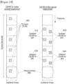
- FIG. 1 illustrates transmission of various signals in a Physical Resource Block (PRB) pair in a Long Term Evolution-Advanced (LTE-A) system according to the related art.
- PRB Physical Resource Block
- LTE-A Long Term Evolution-Advanced
- one PRB pair includes 14 Orthogonal Frequency Division Multiplexing (OFDM)symbols along the time axis and 12 subcarriers along the frequency axis.
- OFDM Orthogonal Frequency Division Multiplexing
- REs Resource Elements
- a Physical Downlink Shared Channel (PDSCH) used for transmission of traffic data, a Cell-Specific Reference Signal (CRS) transmitted for each cell, a Physical Downlink Control Channel (PDCCH) used for transmission of a control signal, a Demodulation Reference Signal (DMRS) used for reception of a PDSCH, and a CSI-RS used for measuring a downlink channel state and generating channel state information are allocated different REs for transmission.
- the CSI-RS supported in an LTE-A system can support signals for one antenna port, 2 antenna ports, 4 antenna ports, and 8 antenna ports, and the number of REs allocated in one PRB pair are different according to the number of antenna ports of the CSI-RS as illustrated in FIG. 1 .
- FIG. 2 illustrates a transmission of a CSI-RS having four antenna ports in one PRB pair in an LTE-A system according to the related art.
- sequences for four CSI-RS antenna ports are spread by orthogonal codes, Code-Division-Multiplexed (CDM), and transmitted to four REs.
- the sequences for CSI-RS port 0 and CSI-RS port 1 are transmitted using the sequences for CSI-RS port 2 and CSI-RS port 3 and another RE pair.
- sequences for a plurality of CSI-RS antenna ports may be transmitted using a plurality of REs.
- an eNB can transmit CSI-RSs for a maximum of 8 transmission antennas
- transmission and reception can be performed using CSI-RSs supporting a maximum of 8 CSI-RS transmission antennas to one transmission point as described above.
- CSI-RSs supporting a maximum of 8 CSI-RS transmission antennas to one transmission point as described above.
- a beam forming gain of a maximum of 9 dB is obtained, so as to improve the Signal to Interference and Noise Ratio (SINR).
- OFDM Orthogonal Frequency Division Multiplexing
- EUTRA Enhanced Universal Mobile Telecommunications System Terrestrial Radio Access
- MIMO Multiple Input Multiple Output
- FIGs. 3 through 15 discussed below, and the various exemplary embodiments used to describe the principles of the present disclosure in this patent document are by way of illustration only and should not be construed in any way that would limit the scope of the disclosure. Those skilled in the art will understand that the principles of the present disclosure may be implemented in any suitably arranged communications system.
- the terms used to describe various embodiments are exemplary. It should be understood that these are provided to merely aid the understanding of the description, and that their use and definitions in no way limit the scope of the invention. Terms first, second, and the like are used to differentiate between objects having the same terminology and are in no way intended to represent a chronological order, unless where explicitly stated otherwise.
- a set is defined as a non-empty set including at least one element.
- FIG. 3 illustrates a structure of a massive MIMO system according to an exemplary embodiment of the present invention.
- a base station transmitter i.e., an evolved Node B (eNB) 300 transmits a wireless signal through scores or more transmission antennas.
- the transmission antennas are arranged while maintaining a minimum distance (e.g., 0.5 ⁇ in FIG. 3 ) between each other as indicated by reference numeral 310.
- the minimum distance may be one-half of the wavelength of the transmitted wireless signal.
- the signal transmitted from each transmission antenna is influenced by a wireless channel having a low correlation.
- the minimum distance is 7.5 cm. As the band of the transmitted wireless channel becomes higher than 2 GHz, this distance becomes shorter.
- the scores or more transmission antennas arranged in the eNB 300 are used in transmitting a signal to one User Equipment (UE)or a plurality of UEs as indicated by reference numeral 320.
- UE User Equipment
- a proper precoding scheme is applied to a plurality of transmission antennas, so as to enable simultaneous transmission to the plurality of transmission antennas.
- one UE can receive one or more spatial channels.
- the number of spatial channels which one UE can receive is determined depending on the number of reception antennas owned by the UE and the channel condition.
- signals transmitted to different UEs may cause interference (i.e., a multi-user MIMO interference) between them, according to the combination of precoding schemes.
- the multi-user MIMO interference has an influence which increases in proportion to the number of UEs simultaneously receiving a signal from an eNB, and weakens the signal receiving performance. More specifically, in a massive MIMO system as illustrated in FIG. 3 , the multi-user MIMO interference is a main factor having an influence on the performance.
- a UE should precisely measure the channel state and the size of interference and transmit effective channel state information to an eNB by using the measured information.
- the eNB determines UEs to which it will make a downlink transmission, a data transmission speed for the transmission, and a precoding scheme to be applied. Since the massive MIMO system includes a large number of transmission antennas, an application of the reference signal transmission method of the related art and its measuring method used in the Long Term Evolution (LTE)/LTE-Advanced (LTE-A) system may cause performance degradation.
- the method of the related art can neither measure the multi-user MIMO interference precisely, which is caused by the simultaneous transmission to a plurality of UEs, nor reflect the interference in the channel state information.
- an exemplary embodiment of the present invention provides an effective Channel State Information-Reference Signal (CSI-RS)transmission and reception method in a massive MIMO system.
- CSI-RS Channel State Information-Reference Signal
- the backward compatibility refers to a function capable of transmitting or receiving a wireless signal to or from UEs of the related art having no capability of receiving a massive MIMO signal, according to a scheme of the related art other than the MIMO scheme, simultaneously while operating a massive MIMO function in an LTE/LTE-A system.
- the backward compatibility needs a capability of simultaneously transmitting a wireless signal to both a UE supporting massive MIMO and a UE not supporting massive MIMO by using the same frequency and time resources while preventing performance degradation of the UE supporting massive MIMO during the transmission or reception of the signal transmitted to the UE not supporting massive MIMO.
- an exemplary embodiment of the present invention proposes a method of transmitting a CSI-RS for a massive MIMO system by using CSI-RS resources of the related art introduced in the LTE-A.
- the CSI-RS resources of the related art introduced in the LTE-A support a maximum of 8 transmission antennas. Therefore, in order to use the CSI-RS resources of the related art, a method capable of transmitting a signal through scores or more transmission antennas is needed.
- an eNB divides the transmission antennas into a plurality of groups.
- FIG. 4 illustrates an antenna grouping according to an exemplary embodiment of the present invention.
- 40 transmission antennas (as indicated by reference numeral 400), which have been grouped into five antenna groups, are illustrated as an example of a massive MIMO system.
- One antenna group includes 8 transmission antennas.
- the grouping is made based on actual transmission antennas in FIG. 4
- the grouping may be made based on virtual transmission antennas other than the actual transmission antennas.
- the antenna grouping may be commonly applied to both the actual transmission antennas and the virtual transmission antennas.
- a virtual transmission antenna refers to an individual antenna signal which can be identified by a UE, and is implemented by a signal transmitted from an actual transmission antenna.
- CSI-RSs for massive MIMO are transmitted to each UE for each group of multiple antennas as illustrated in FIG. 4 , so that CSI-RSs for more transmission antennas than the 8 transmission antennas supported by the LTE-A are transmitted.
- FIG. 5 illustrates transmission of CSI-RSs for massive MIMO according to an exemplary embodiment of the present invention.
- the CSI-RSs for massive MIMO are transmitted at different time intervals according to the respective antenna groups in FIG. 4 .
- one time interval corresponds to one subframe in an LTE/LTE-A system.
- the subframe is a time unit used for resource allocation in an LTE/LTE-A system and corresponds to 1 msec.
- antenna groups 1 through 5 in FIG. 4 are allocated transmission time intervals and transmit CSI-RSs in the allocated transmission time intervals.
- each antenna group since each antenna group includes 8 transmission antennas, each antenna group transmits a CSI-RS in each transmission interval by using one CSI-RS resource (as indicated by reference numeral 500 of FIG. 5 ) for 8 ports.
- each transmission antenna has an individual transmission resource in transmitting a CSI-RS, and the UE can measure the channel state in each transmission antenna.
- the channel state in each transmission antenna needs to be measured for determination of an optimum precoding scheme in massive MIMO.
- UEs which do not support massive MIMO cannot receive signals transmitted from a large number of antennas as illustrated in FIG. 4 in a discriminated manner according to the antennas.
- CSI-RS 510 for massive MIMO separately from the CSI-RS 510 for massive MIMO, CSI-RSs 520 for non-massive MIMO with respect to all antenna groups are transmitted.
- the CSI-RSs 520 may be transmitted through a virtual antenna.
- the CSI-RSs for non-massive MIMO may also be effectively used for simultaneous signal transmission to a plurality of UEs.
- UEs which do not support massive MIMO can receive non-massive MIMO CSI-RSs for a maximum of 8 transmission antennas supported in the LTE-A.
- Such UEs cannot receive the CSI-RSs 510 for massive MIMO of FIG. 5 and measure the channel state of each transmission antenna. Therefore, for such UEs, the eNB implements a smaller number of virtual transmission antennas than the number of actual transmission antennas and transmits a signal for these antennas through one CSI-RS resource.
- the UEs When CSI-RSs for non-massive MIMO are transmitted for the UEs which do not support massive MIMO as described above, the UEs cannot discriminately measure the channel state of the individual transmission antennas. However, a plurality of transmission antennas are allocated to each virtual transmission antenna and a relatively higher transmission power is thus used for signal transmission. Furthermore, the higher the transmission power allocated to each virtual transmission antenna, the more precise the channel state measured by a UE.
- an individual time resource allocated to each antenna group is used for transmission of CSI-RSs for massive MIMO in FIG. 5 , not only the individual time resource but also an individual frequency resource may be allocated for transmission of the CSI-RSs for massive MIMO.
- FIG. 6 illustrates a transmission of CSI-RSs for massive MIMO by allocation of individual frequency resources according to an exemplary embodiment of the present invention.
- CSI-RSs 600 for massive MIMO are transmitted in a time interval corresponding to one subframe. It is noted from FIG. 6 that CSI-RSs 610 for a plurality of antenna groups are transmitted by different OFDM symbols or subcarriers within the same subframe.
- an eNB In order to transmit the CSI-RSs for massive MIMO as illustrated in FIGs. 5 and 6 , an eNB should notify a UE of related control information before transmitting a CSI-RS.
- the control information is imperative for proper reception of the CSI-RSs for massive MIMO and proper determination of the channel state based on the received CSI-RSs by the UE.
- Such control information may include at least one of the following:
- control information may include at least one of the following:
- the information on the transmission power of the CSI-RSs for massive MIMO and the information on the transmission power of the CSI-RSs for non-massive MIMO are control information used for a UE to receive each CSI-RS and determine a precise channel state.
- the control information relating to the CSI-RSs for massive MIMO and the control information relating to the CSI-RSs for non-massive MIMO are transferred to the UE, separately from the CSI-RSs. According to whether the information relates to massive MIMO or non-massive MIMO, different methods are used in determining the channel state. Therefore, for effective communication, the UE needs to know whether the above two types of information are for massive MIMO or non-massive MIMO.
- the UE may receive both the control information relating to the CSI-RSs for massive MIMO and the control information relating to the CSI-RSs for non-massive MIMO, and the eNB may send additional control information, by which it is possible to determine whether the control information is for massive MIMO or for non-massive MIMO, to the UE.
- the above description discusses a method of transmitting CSI-RSs for massive MIMO after dividing the CSI-RSs according to the antenna groups.
- a UE determines the channel state information by measuring the channel state of each antenna. Therefore, allocation of individual transmission resources is imperative for channel measurement of each antenna.
- This method can be effectively used when sufficient transmission power can be allocated to each transmission antenna.
- it is more efficient to generate a plurality of beams by an eNB and select one or more beams among the generated beams by the UE, than to measure the channel state of each antenna.
- each beam is transmitted using an individual transmission resource and beams are generated using the same multiple transmission antennas, but different precoding schemes are applied to the antennas according to the beams. For example, although beam1 and beam2 are transmitted using the same 40 transmission antennas, the precoding scheme applied to beam1 and the precoding scheme applied to beam2 are different from each other.
- the plurality of beams may be grouped into a plurality of beam groups for transmission, as in the above case of grouping the multiple transmission antennas into multiple antenna groups for transmission.
- FIG. 7 illustrates a grouping of a plurality of beams into five beam groups, wherein each beam group is transmitted in an individual time interval, according to an exemplary embodiment of the present invention.
- each antenna group includes 8 transmission antennas, and each antenna group transmits CSI-RSs by using one CSI-RS resource 700 for 8 ports in each transmission interval.
- CSI-RSs for massive MIMO are transmitted using a particular CSI-RS resource within a subframe as indicated by reference numeral 720, CSI-RSs for a large number of beams may be transmitted by performing transmission for different beam groups according to subframes.
- FIG. 8 illustrates a transmission of CSI-RSs for a plurality of beams by allocating not only individual time resources but also individual frequency resources according to an exemplary embodiment of the present invention.
- CSI-RSs 800 for massive MIMO transmitted in a time interval corresponding to one subframe and individual frequency resources 810 are illustrated.
- a system using massive MIMO may have scores or more transmission antennas.
- simultaneous transmission of wireless signals to a large number of UEs is needed.
- a signal for other UEs may generate a multi-user MIMO interference and the size of the interference increases according to an increase in the number of UEs participating in the multi-user MIMO.
- one UE among the 10 UEs may be subjected to multi-user MIMO interference by the signals transmitted from the other 9 UEs, which causes performance degradation of the one UE.
- a UE since signal transmission to a large number of UEs is simultaneously performed, it may be necessary to use, in spite of an optimum precoding in view of a particular UE, another precoding in consideration of the quantity of interference incurred to another UE.
- a UE In a case of an LTE/LTE-A system, a UE notifies an eNB of a precoding optimum for the UE together with information on supportable data rates when the optimum precoding is applied. Since the information on the supportable data rates is available only when the precoding is applied, it is impossible to know the data rates which the UE can support when the eNB applies a precoding which is not requested by the UE. In general, this problem is known as an inaccuracy of the link adaption.
- An exemplary embodiment of the present invention proposes a link adaptation method for addressing the problems occurring due to the inaccuracy of the link adaption as described above.
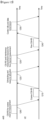
- FIG. 9 illustrates a link adaptation method according to an exemplary embodiment of the present invention.
- an eNB transmits a CSI-RS (i.e., a coarse CSI) 900 for first channel measurement to a LTE.
- the LTE Upon receiving the CSI-RS, the LTE notifies the eNB of first channel state information 910 by using the CSI-RS.
- the CSI-RS 900 for the first channel measurement is a periodic signal
- the first channel state information 910 may also be periodically notified information.
- the first channel state information 910 may be notified of by each of multiple UEs.
- the eNB first determines UEs to which wireless resources for data transmission are to be allocated, in the step indicated by reference numeral 920.
- the selected UEs are known as wireless resource allocation candidate UEs.
- the wireless resource allocation candidate UEs determined by the eNB in the step indicated by reference numeral 920 are notified that they should receive second CSI-RSs from the eNB.
- the wireless resource allocation 920 and the second CSI-RS notification 930 may be simultaneously performed in the same time interval.
- the UE having received the second CSI-RS i.e., fine CSI-RS notifies the eNB of second channel state information by using the second CSI-RS.
- the eNB Upon receiving the second channel state information, the eNB selects UEs to which actual downlink wireless resources are to be allocated, and transmits control information needed for reception of a traffic channel to the selected UEs, in the step indicated by reference numeral 950.
- the UEs allocated the actual downlink wireless resources may be different from the wireless resource allocation candidate UEs.
- the second CSI-RS is different from the first CSI-RS in view of at least one of the following:
- the second channel state information transmitted by the UE having received the second CSI-RS may be reported by means of a value relative to the first channel state information. For example, if a Signal to Interference and Noise Ratio (SINR) or a data rate among the first channel state information is A and an SINR or a data rate measured by a UE having received a second CSI-RS is (A+), the UE does not notify (A+) but notifies only as the second channel state information.
- SINR Signal to Interference and Noise Ratio
- A+ Signal to Interference and Noise Ratio
- Such transmission of a relative value as the channel state information as described above reduces the information quantity of the second channel state information, so as to reduce the overhead in the uplink transmission by the UE.
- FIG. 10 illustrates a transmission of a first CSI-RS and a second CSI-RS in a frequency band according to an exemplary embodiment of the present invention.
- the first CSI-RS 1000 is a signal which is transmitted in all Resource Blocks (RBs) of the system bandwidth and is received by a plurality of UEs.
- the second CSI-RSs 1010, 1020, 1030, and 1040 are signals, which may be individually allocated to UEs and may be transmitted in only some of the RBs of the system bandwidth.
- a plurality of second CSI-RSs may be transmitted in the same subframe and RB.
- the second CSI-RSs 1010 and 1020 are signals for different UEs, they are transmitted using the same RB in the same subframe.
- the eNB In order to receive the second CSI-RSs, the eNB should transfer control information for receiving the second CSI-RSs to the UE.
- the control information for receiving the second CSI-RSs may be notified to the UE by the eNB through transmission as indicated by reference numeral 920 in FIG. 9 .
- the control information includes at least one of the following:
- the control information is imperative for reception of a second CSI-RS allocated to a UE by the UE.
- the eNB may notify a corresponding UE of information needed for reception of a second CSI-RS allocated to UEs other than the corresponding UE.
- the reason why the eNB notifies a UE of information needed for reception of a second CSI-RS allocated to the other UEs is in order to enable the UE to measure the multi-user MIMO interference generated at the time of multi-user MIMO transmission by receiving the second CSI-RS allocated to the other UEs.
- the information imperative for reception of the second CSI-RS may be transmitted through a Physical Downlink Control Channel (PDCCH) or an Enhanced-PDCCH(E-PDCCH), which are control channels supported in the LTE/LTE-A.
- PDCCH Physical Downlink Control Channel
- E-PDCCH Enhanced-PDCCH
- Notification of all information relating to the second CSI-RS to a UE by using a PDCCH or an E-PDCCH as described above may generate an excessive downlink overhead.
- some of the information may be set using a higher layer signaling while only indispensible information is transmitted using a PDCCH or an E-PDCCH.
- the second CSI-RS of FIG. 10 is not transmitted in all frequency bands but is transmitted in fewer than all of the frequency bands.
- the reason why the second CSI-RS is transmitted in fewer than all of the frequency bands is to transmit the second CSI-RS in the same band as the frequency band in which a data signal is transmitted. Accordingly, it is possible to precisely determine the channel state of the frequency band in which the data is transmitted.
- One method capable of reducing the quantity of control information for the second CSI-RS, which should be transmitted through a PDCCH or an E-PDCCH, is to semi-statically set the transmission resources for the second CSI-RS.
- FIG. 11 illustrates a transmission of first CSI-RSs and second CSI-RSs for respective subframes according to an exemplary embodiment of the present invention.
- first CSI-RSs and second CSI-RSs are simultaneously transmitted in subframe 0.
- both the first CSI-RSs and second CSI-RSs are transmitted using CSI-RS transmission resources 1100, 1110, 1120, and 1130.
- only the second CSI-RSs are transmitted using CSI-RS transmission resources 1140, 1150, 1160, and 1170.
- the CSI-RS transmission resources 1100, 1110, 1120, and 1130 have been allocated to UEs appointed by the eNB.
- the CSI-RS transmission resource 1100 has been allocated to enable UEs belonging to Group A to receive the second CSI-RS.
- a UE belonging to Group A when a UE belonging to Group A receives a notification from the eNB that a second CSI-RS for the UE itself is allocated to a particular RB or RBs, the UE can identify a CSI-RS transmission resource in which the second CSI-RS for the UE itself exists, among a plurality of CSI-RS transmission resources existing in the particular RB or RBs.
- This method can reduce the downlink overhead because it makes it unnecessary for the UE to transmit, through a PDCCH or an E-PDCCH, separate control information about which one is allocated among a plurality of CSI-RS transmission resources.
- the UE can identify that the second CSI-RS for the UE itself exists in the CSI-RS transmission resource 1100 and that CSI-RSs for other UEs exist in the other CSI-RS transmission resources 1110, 1120, and 1130. By using this information, the UE can determine a multi-user MIMO interference generated in the same RB(s) as that of the UE itself by measuring the reception power carried by the CSI-RS transmission resources 1110, 1120, and 1130.
- predefined CSI-RS resources are set for the second CSI-RSs as illustrated in FIG. 11 , at least one of the following should be notified to a UE by using a higher layer signaling:
- the UE When the UE having received the information described above receives a notification that a second CSI-RS has been allocated to itself through a PDCCH or an E-PDCCH, the UE receives a signal for measurement of a wireless channel in the CSI-RS transmission resource through which the second CSI-RS of the UE itself is transmitted and receives a signal for measurement of a multi-user MIMO interference in the other CSI-RS transmission resource.
- a UE For effective data transmission and reception using massive MIMO, a UE needs to effectively determine a multi-user MIMO interference generated in massive MIMO transmission and reception.
- exemplary embodiments of the present invention can be applied to a method of measuring a multi-user MIMO interference by directly measuring second CSI-RSs allocated to other UEs and a method of measuring a multi-user MIMO interference by allocating an interference measurement resource to each UE to which a second CSI-RS is allocated.
- the interference measurement resource refers to a wireless resource used when a particular UE measures the size of interference applied to the particular UE itself, and is used when a UE has received a second CSI-RS and needs to determine a precise channel state information.
- the interference measurement resource includes one or more REs, through which a wireless signal transmitted to a UE allocated the interference measurement resource is not carried and only wireless signals transmitted to the other UEs are carried. For example, when UE1 has been allocated a particular interference measurement resource, the eNB transmits only transmission signals for the other UEs without transmitting a transmission signal for UE1 through the particular interference measurement resource, so that UE1 can measure only the multi-user MIMO interference. The UE having received only the transmission signals for the other UEs through the particular interference measurement resource can measure a precise multi-user MIMO interference.
- Each UE may be notified of whether the interference measurement resource has been allocated or not, through a PDCCH or an E-PDCCH.
- the eNB may notify allocation of the interference measurement resource to the UE simultaneously while notifying whether the second CSI-RS has been allocated.
- FIG. 12 illustrates a notification of an allocation-or-not of a second CSI-RS and an allocation of an interference measurement resource to a UE by an eNB according to an exemplary embodiment of the present invention.
- an eNB transmits a CSI-RS (i.e., a coarse CSI) 1200 for first channel measurement to a UE.
- a CSI-RS i.e., a coarse CSI
- the UE Upon receiving the CSI-RS, the UE notifies the eNB of first channel state information 1210 by using the CSI-RS.
- the CSI-RS 1200 for the first channel measurement is a periodic signal
- the first channel state information 1210 may also be periodically notified information.
- the first channel state information 1210 may be notified of by each of multiple UEs.
- the eNB selects wireless resource allocation candidate UEs, in the step indicated by reference numeral 1220.
- the wireless resource allocation candidate UEs determined by the eNB in the step indicated by reference numeral 1220 are notified that they should receive second CSI-RSs from the eNB.
- the eNB notifies allocation of the second CSI-RS and the interference measurement resource to the UE.
- the wireless resource allocation 1220 and the second CSI-RS notification 1230 may be simultaneously performed in the same time interval.
- the UE having received the second CSI-RS notifies the eNB of second channel state information by using the second CSI-RS.
- the eNB selects UEs to which actual downlink wireless resources are to be allocated, and transmits control information needed for reception of a traffic channel to the selected UEs, in the step indicated by reference numeral 1250.
- the control information for notification of the interference measurement resource transmitted in the step indicated by reference numeral 1230 includes at least one of the following:
- an interference measurement resource is allocated using a control channel, such as a PDCCH or an E-PDCCH
- a control channel such as a PDCCH or an E-PDCCH
- an interference measurement resource of a fixed position is allocated using a higher layer signaling.
- the UE uses an interference measurement resource set through a higher layer signaling among RBs in which the second CSI-RSs exist.
- This exemplary method is advantageous in that it is not necessary to transmit separate control information through a PDCCH or an E-PDCCH in order to allocate an interference measurement resource.
- Another exemplary method is to link an interference measurement resource and a CSI-RS transmission resource of a second CSI-RS.
- an interference measurement resource allocated to a UE becomes different according to the CSI-RS transmission resource used by the second CSI-RS allocated to the UE.
- FIG. 13 illustrates an allocation of interference measurement resources in a frequency band according to an exemplary embodiment of the present invention.
- the first CSI-RS 1300 is a signal which is transmitted in all RBs of the system bandwidth and is received by a plurality of UEs.
- a specific second CSI-RS and a specific interference measurement resource have been allocated to each of the two UEs in the two same RBs.
- UE1 measures the channel state of the wireless channel by using the second CSI-RSs 1310 and measures the quantity of interference by using the interference measurement resources 1320.
- UE2 measures the channel state of the wireless channel by using the second CSI-RSs 1330 and measures the quantity of interference by using the interference measurement resources 1340. It is noted that the interference measurement resources and the second CSI-RSs occupy the same frequency band.
- Such occupying of the same frequency band is intended to enable channel estimation and interference measurement to be performed in the frequency band in which actual data is to be transmitted, so as to obtain a more precise determination of the channel state information.
- the interference measurement resources and the second CSI-RSs are not transmitted in all frequency bands but are transmitted in fewer than all of the frequency bands. Such transmission in fewer than all of the frequency bands is also performed in only the same band as a particular frequency band in which a data signal is to be transmitted, so as to obtain a more precise determination of the channel state information of the particular frequency band in which the data signal is to be transmitted.
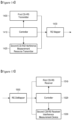
- FIG. 14 illustrates a transmission apparatus according to an exemplary embodiment of the present invention.
- a controller 1410 determines whether to transmit a signal generated in a first CSI-RS transmitter 1400 and a signal generated in a second CSI-RS/interference measurement resource transmitter 1420.
- the first CSI-RS signal is a periodically transmitted signal and is transmitted in order to measure channels for a plurality of transmission antennas or a plurality of beams generated by a plurality of transmission antennas.
- the eNB determines, in each subframe, a time interval in which the second CSI-RS is to be transmitted, a UE to which the second CSI-RS is to be transmitted, and a frequency band in which the second CSI-RS is to be transmitted.
- the signal is transmitted while being carried by a Resource Element (RE) to be transmitted by an RE mapper 1430.
- the controller 1410 notifies control information on transmission of the second CSI-RS and the interference measurement resource to each UE by using a PDCCH or an E-PDCCH.
- the information needed for reception of the second CSI-RS or the interference measurement resource by each UE may include a part which the UE can determine according to a predefined rule between the UE and an eNB.
- FIG. 15 illustrates a reception apparatus according to an exemplary embodiment of the present invention.
- received wireless signals are classified into first CSI-RSs, second CSI-RSs, and interference measurement resources by an RE demapper 1500, which are then input to a first CSI-RS receiver 1510 and a second CSI-RS/interference measurement resource receiver 1530, respectively.
- the first CSI-RS receiver 1510 is a receiver for receiving signals transmitted in all frequency bands
- the second CSI-RS/interference measurement resource receiver 1530 is a receiver for receiving only signals transmitted in the time intervals and frequency bands allocated by the eNB.
- a controller 1520 determines the time interval and the frequency band in which the second CSI-RS/interference measurement resource receiver 1530 is to receive a signal.
- the controller 1520 is notified of the determination by receiving a PDCCH or an E-PDCCH from the eNB or identifies the corresponding information based on a predefined rule between the eNB and the UE as described above.
- a reference signal in a MIMO system having scores or more transmission antennas. Furthermore, according to exemplary embodiments of the present invention, it is possible to allocate resources to a reference signal and measure an interference signal in a MIMO system having scores or more transmission antennas.
Description
- The present invention relates to a wireless mobile communication system. More particularly, the present invention relates to a method for effectively transmitting and receiving a Channel State Information-Reference Signal (CSI-RS) and measuring interference.
- Current mobile communication systems are developing, beyond the initial level of providing voice-oriented services, into a high quality wireless packet data communication system in order to provide a data service and a multimedia service. To this end, various standardization organizations, such as the 3rd Generation Partnership Project (3GPP), the 3GPP2, and the Institute of Electrical and Electronics Engineers (IEEE), are preparing 3rd generation evolution mobile communication system standards employing multiple access schemes using multi-carriers. Recently, various mobile communication standards, including Long Term Evolution (LTE) of the 3GPP, Ultra Mobile Broadband (UMB) of the 3GPP2, and 802.16m of the IEEE, have been developed in order to support a high speed-high quality wireless packet data transmission service based on a multiple access scheme using a multi-carrier.
- The current 3rd generation evolution mobile communication systems, such as LTE, UMB, and 802.16m, are based on a multiple carrier multiple access scheme, employ multiple antennas based on a Multiple Input Multiple Output (MIMO) scheme, and use various technologies, such as beam-forming, Adaptive Modulation and Coding (AMC), channel sensitive scheduling, and the like. These technologies improve the system capacity performance by, for example, concentrating a transmission power of multiple antennas or controlling the quantity of data transmitted from the antennas according to the channel qualities and selectively transmitting data to a user having a good channel quality. These techniques are based on the channel state information between a base station or an evolved Node B (eNB) and a mobile station or a User Equipment (UE). Therefore, an eNB or a UE needs to measure the channel state between them, and a CSI-RS is used in the measurement. The eNB refers to an apparatus for downlink transmission and uplink reception, which is located at a predefined position, and one eNB performs transmission and reception with respect to cells. In one mobile communication system, a plurality of eNBs are geographically scattered and each eNB performs transmission and reception with respect to the cells.
- A reference signal is a signal used for demodulation and decoding of a received data symbol by measuring channel states, such as the intensity or distortion of a channel, the intensity of interference, Gaussian noise, or the like, between an eNB and a UE. Furthermore, a receiver can determine the channel state of a wireless channel between the receiver and a transmitter by measuring an intensity of a signal received through the wireless channel, which has been transmitted with a predefined transmission power by the transmitter. The measured channel state of the wireless channel is used by the receiver to determine a data rate which the receiver will request from the transmitter.
- The resources of time, frequency, and transmission power are limited in a mobile communication system. Therefore, an increase in the quantity of resources allocated to a reference signal may decrease the quantity of resources that can be allocated to transmission of traffic channels and thus may reduce the absolute quantity of transmitted data. In this case, although the performances of channel measurement and estimation may be improved, the reduced absolute quantity of transmitted data may rather decrease the performance of the entire system throughput. Therefore, in order to obtain an optimum performance in view of the entire system throughput, a proper distribution between resources for the reference signal and resources for transmission of traffic channels is necessary.
-
WO2011/105726A2 discloses a method and apparatus for providing information indicating radio resources for multi-cell interference measurement at a BS so that a UE can more accurately measure interference. -
WO2011/100672A1 discloses a system and a method of receiving a channel state information reference signal (CSI-RS). At a user equipment, a first CSI-RS transmitted from a base station is received. In some implementations, the first CSI-RS is transmitted at a first periodicity using a first set of antenna ports. At the user equipment, a second CSI-RS transmitted from the base station is received. In some implementations, the second CSI-RS is transmitted at a second periodicity using a second set of antenna ports. At least one of the first CSI-RS and the second CSI-RS issued to perform channel measurement. -
WO2011/115421 A2 discloses a method and apparatus for providing channel state information-reference signal (CSI-RS) configuration information in a wireless communication system supporting multiple antennas. -
FIG. 1 illustrates transmission of various signals in a Physical Resource Block (PRB) pair in a Long Term Evolution-Advanced (LTE-A) system according to the related art. - Referring to
FIG. 1 , one PRB pair includes 14 Orthogonal Frequency Division Multiplexing (OFDM)symbols along the time axis and 12 subcarriers along the frequency axis. The 14 OFDM symbols and the 12 subcarriers form 168 (= 14 X 12) Resource Elements (REs), wherein each RE corresponds to a resource having an orthogonality with respect to a neighboring RE. In the PRB pair, a Physical Downlink Shared Channel (PDSCH) used for transmission of traffic data, a Cell-Specific Reference Signal (CRS) transmitted for each cell, a Physical Downlink Control Channel (PDCCH) used for transmission of a control signal, a Demodulation Reference Signal (DMRS) used for reception of a PDSCH, and a CSI-RS used for measuring a downlink channel state and generating channel state information are allocated different REs for transmission. The CSI-RS supported in an LTE-A system can support signals for one antenna port, 2 antenna ports, 4 antenna ports, and 8 antenna ports, and the number of REs allocated in one PRB pair are different according to the number of antenna ports of the CSI-RS as illustrated inFIG. 1 . -
FIG. 2 illustrates a transmission of a CSI-RS having four antenna ports in one PRB pair in an LTE-A system according to the related art. - Referring to
FIG. 2 , as indicated byreference numerals RS port 0 and CSI-RS port 1 are transmitted using the sequences for CSI-RS port 2 and CSI-RS port 3 and another RE pair. In this way, sequences for a plurality of CSI-RS antenna ports may be transmitted using a plurality of REs. In a case of an LTE-A system, since transmission to a maximum of 8 CSI-RS antenna ports is possible, an eNB can transmit CSI-RSs for a maximum of 8 transmission antennas - In the case of an LTE-A system, transmission and reception can be performed using CSI-RSs supporting a maximum of 8 CSI-RS transmission antennas to one transmission point as described above. In a case of performing a beam forming transmission using a maximum of 8 transmission antennas, a beam forming gain of a maximum of 9 dB is obtained, so as to improve the Signal to Interference and Noise Ratio (SINR).
- Therefore, a need exists for a method and an apparatus for transmitting a reference signal for effective data transmission and reception, measuring interference, and generating channel state information in a MIMO transmission and reception.
- The above information is presented as background information only to assist with an understanding of the present disclosure. No determination has been made, and no assertion is made, as to whether any of the above might be applicable as prior art with regard to the present invention.
- Aspects of the present invention are to address at least the above-mentioned problems and/or disadvantages and to provide at least the advantages described below. Accordingly, the present invention is defined in the appended claims.
-
-
FIG. 1 illustrates a transmission of various signals in a Physical Resource Block (PRB) pair in a Long Term Evolution-Advanced (LTE-A) system according to the related art -
FIG. 2 illustrates a transmission of a Channel State Information-Reference Signal (CSI-RS)having four antenna ports in one PRB pair in an LTE-A system according to the related art -
FIG. 3 illustrates a structure of a massive Multiple Input Multiple Output (MIMO) system according to an exemplary embodiment of the present invention -
FIG. 4 illustrates an antenna grouping according to an exemplary embodiment of the present invention; -
FIG. 5 illustrates a transmission of CSI-RSs for massive MIMO according to an exemplary embodiment of the present invention; -
FIG. 6 illustrates a transmission of CSI-RSs for massive MIMO by allocation of individual frequency resources according to an exemplary embodiment of the present invention; -
FIG. 7 illustrates a grouping of a plurality of beams into five beam groups, wherein each beam group is transmitted in an individual time interval, according to an exemplary embodiment of the present invention -
FIG. 8 illustrates a transmission of CSI-RSs for a plurality of beams by allocating not only individual time resources but also individual frequency resources according to an exemplary embodiment of the present invention; -
FIG. 9 illustrates a link adaptation method according to an exemplary embodiment of the present invention; -
FIG 10 illustrates a transmission of a first CSI-RS and a second CSI-RS in a frequency band according to an exemplary embodiment of the present invention; -
FIG. 11 illustrates a transmission of first CSI-RSs and second CSI-RSs for respective subframes according to an exemplary embodiment of the present invention; -
FIG 12 illustrates a notification of an allocation-or-not of a second CSI-RS and an allocation of an interference measurement resource to a User Equipment (UE) by an evolved Node B (eNB) according to an exemplary embodiment of the present invention; -
FIG 13 illustrates an allocation of interference measurement resources in a frequency band according to an exemplary embodiment of the present invention; -
FIG. 14 illustrates a transmission apparatus according to an exemplary embodiment of the present invention; and -
FIG. 15 illustrates a reception apparatus according to an exemplary embodiment of the present invention. - The following description with reference to the accompanying drawings is provided to assist in a comprehensive understanding of exemplary embodiments of the invention as defined by the claims and their equivalents. It includes various specific details to assist in that understanding but these are to be regarded as merely exemplary. Accordingly, those of ordinary skill in the art will recognize that various changes and modifications of the embodiments described herein can be made without departing from the scope of the invention as defined by the claims. In addition, descriptions of well-known functions and constructions may be omitted for clarity and conciseness.
- The terms and words used in the following description and claims are not limited to the bibliographical meanings, but, are merely used by the inventor to enable a clear and consistent understanding of the invention. Accordingly, it should be apparent to those skilled in the art that the following description of exemplary embodiments of the present invention is provided for illustration purpose only and not for the purpose of limiting the invention as defined by the appended claims and their equivalents.
- It is to be understood that the singular forms "a," "an," and "the" include plural referents unless the context clearly dictates otherwise. Thus, for example, reference to "a component surface" includes reference to one or more of such surfaces.
- By the term "substantially" it is meant that the recited characteristic, parameter, or value need not be achieved exactly, but that deviations or variations, including for example, tolerances, measurement error, measurement accuracy limitations and other factors known to those of skill in the art, may occur in amounts that do not preclude the effect the characteristic was intended to provide.
- Furthermore, although the following detailed description of exemplary embodiments of the present invention mainly discusses an Orthogonal Frequency Division Multiplexing (OFDM) based wireless communication system, especially an Enhanced Universal Mobile Telecommunications System Terrestrial Radio Access (EUTRA) standard of the 3rd Generation Partnership Project (3GPP), the principal idea of the present invention can be applied to other communication systems having similar technical backgrounds and channel types with slight modifications without departing from the scope of the present invention.
- First, an exemplary method of effective transmission and reception of a reference signal in a massive Multiple Input Multiple Output (MIMO) wireless communication system which transmits data by using scores or more transmission antennas will be described
-
FIGs. 3 through 15 , discussed below, and the various exemplary embodiments used to describe the principles of the present disclosure in this patent document are by way of illustration only and should not be construed in any way that would limit the scope of the disclosure. Those skilled in the art will understand that the principles of the present disclosure may be implemented in any suitably arranged communications system. The terms used to describe various embodiments are exemplary. It should be understood that these are provided to merely aid the understanding of the description, and that their use and definitions in no way limit the scope of the invention. Terms first, second, and the like are used to differentiate between objects having the same terminology and are in no way intended to represent a chronological order, unless where explicitly stated otherwise. A set is defined as a non-empty set including at least one element. -
FIG. 3 illustrates a structure of a massive MIMO system according to an exemplary embodiment of the present invention. - Referring to
FIG. 3 , a base station transmitter (i.e., an evolved Node B (eNB)) 300 transmits a wireless signal through scores or more transmission antennas. The transmission antennas are arranged while maintaining a minimum distance (e.g., 0.5λinFIG. 3 ) between each other as indicated byreference numeral 310. For example, the minimum distance may be one-half of the wavelength of the transmitted wireless signal. In general, when a distance corresponding to one-half of a wavelength of a transmitted wireless signal is maintained between transmission antennas, the signal transmitted from each transmission antenna is influenced by a wireless channel having a low correlation. When a band of a transmitted wireless channel is 2 GHz, the minimum distance is 7.5 cm. As the band of the transmitted wireless channel becomes higher than 2 GHz, this distance becomes shorter. - Referring to
FIG. 3 , the scores or more transmission antennas arranged in theeNB 300 are used in transmitting a signal to one User Equipment (UE)or a plurality of UEs as indicated byreference numeral 320. A proper precoding scheme is applied to a plurality of transmission antennas, so as to enable simultaneous transmission to the plurality of transmission antennas. At this time, one UE can receive one or more spatial channels. In general, the number of spatial channels which one UE can receive is determined depending on the number of reception antennas owned by the UE and the channel condition. However, in the case of simultaneous transmission to a plurality of UEs as illustrated inFIG. 3 , signals transmitted to different UEs may cause interference (i.e., a multi-user MIMO interference) between them, according to the combination of precoding schemes. The multi-user MIMO interference has an influence which increases in proportion to the number of UEs simultaneously receiving a signal from an eNB, and weakens the signal receiving performance. More specifically, in a massive MIMO system as illustrated inFIG. 3 , the multi-user MIMO interference is a main factor having an influence on the performance. - Therefore, in order to effectively implement a massive MIMO system, a UE should precisely measure the channel state and the size of interference and transmit effective channel state information to an eNB by using the measured information. Upon receiving the channel state information from the UE, the eNB determines UEs to which it will make a downlink transmission, a data transmission speed for the transmission, and a precoding scheme to be applied. Since the massive MIMO system includes a large number of transmission antennas, an application of the reference signal transmission method of the related art and its measuring method used in the Long Term Evolution (LTE)/LTE-Advanced (LTE-A) system may cause performance degradation. Furthermore, the method of the related art can neither measure the multi-user MIMO interference precisely, which is caused by the simultaneous transmission to a plurality of UEs, nor reflect the interference in the channel state information.
- Therefore, an exemplary embodiment of the present invention provides an effective Channel State Information-Reference Signal (CSI-RS)transmission and reception method in a massive MIMO system.
- In a massive MIMO transmission and reception based on an LTE/LTE-A system, an important subject is to maintain the backward compatibility. Here, the backward compatibility refers to a function capable of transmitting or receiving a wireless signal to or from UEs of the related art having no capability of receiving a massive MIMO signal, according to a scheme of the related art other than the MIMO scheme, simultaneously while operating a massive MIMO function in an LTE/LTE-A system. For example, the backward compatibility needs a capability of simultaneously transmitting a wireless signal to both a UE supporting massive MIMO and a UE not supporting massive MIMO by using the same frequency and time resources while preventing performance degradation of the UE supporting massive MIMO during the transmission or reception of the signal transmitted to the UE not supporting massive MIMO.
- In order to satisfy the conditions as described above, an exemplary embodiment of the present invention proposes a method of transmitting a CSI-RS for a massive MIMO system by using CSI-RS resources of the related art introduced in the LTE-A. The CSI-RS resources of the related art introduced in the LTE-A support a maximum of 8 transmission antennas. Therefore, in order to use the CSI-RS resources of the related art, a method capable of transmitting a signal through scores or more transmission antennas is needed. In order to transmit a CSI-RS through scores or more transmission antennas by using limited resources as described above, an eNB divides the transmission antennas into a plurality of groups.
-
FIG. 4 illustrates an antenna grouping according to an exemplary embodiment of the present invention. - Referring to
FIG. 4 , 40 transmission antennas (as indicated by reference numeral 400), which have been grouped into five antenna groups, are illustrated as an example of a massive MIMO system. One antenna group includes 8 transmission antennas. Although the grouping is made based on actual transmission antennas inFIG. 4 , the grouping may be made based on virtual transmission antennas other than the actual transmission antennas. Furthermore, the antenna grouping may be commonly applied to both the actual transmission antennas and the virtual transmission antennas. In general, a virtual transmission antenna refers to an individual antenna signal which can be identified by a UE, and is implemented by a signal transmitted from an actual transmission antenna. - CSI-RSs for massive MIMO are transmitted to each UE for each group of multiple antennas as illustrated in
FIG. 4 , so that CSI-RSs for more transmission antennas than the 8 transmission antennas supported by the LTE-A are transmitted. -
FIG. 5 illustrates transmission of CSI-RSs for massive MIMO according to an exemplary embodiment of the present invention. - Referring to
FIG. 5 , the CSI-RSs for massive MIMO are transmitted at different time intervals according to the respective antenna groups inFIG. 4 . InFIG. 5 , one time interval corresponds to one subframe in an LTE/LTE-A system. The subframe is a time unit used for resource allocation in an LTE/LTE-A system and corresponds to 1 msec. For example,antenna groups 1 through 5 inFIG. 4 are allocated transmission time intervals and transmit CSI-RSs in the allocated transmission time intervals. InFIG. 4 , since each antenna group includes 8 transmission antennas, each antenna group transmits a CSI-RS in each transmission interval by using one CSI-RS resource (as indicated byreference numeral 500 ofFIG. 5 ) for 8 ports. In the transmission described above, each transmission antenna has an individual transmission resource in transmitting a CSI-RS, and the UE can measure the channel state in each transmission antenna. The channel state in each transmission antenna needs to be measured for determination of an optimum precoding scheme in massive MIMO. In contrast, UEs which do not support massive MIMO cannot receive signals transmitted from a large number of antennas as illustrated inFIG. 4 in a discriminated manner according to the antennas. For such UEs, separately from the CSI-RS 510 for massive MIMO, CSI-RSs 520 for non-massive MIMO with respect to all antenna groups are transmitted. The CSI-RSs 520 may be transmitted through a virtual antenna. Furthermore, the CSI-RSs for non-massive MIMO may also be effectively used for simultaneous signal transmission to a plurality of UEs. UEs which do not support massive MIMO can receive non-massive MIMO CSI-RSs for a maximum of 8 transmission antennas supported in the LTE-A. Such UEs cannot receive the CSI-RSs 510 for massive MIMO ofFIG. 5 and measure the channel state of each transmission antenna. Therefore, for such UEs, the eNB implements a smaller number of virtual transmission antennas than the number of actual transmission antennas and transmits a signal for these antennas through one CSI-RS resource. When CSI-RSs for non-massive MIMO are transmitted for the UEs which do not support massive MIMO as described above, the UEs cannot discriminately measure the channel state of the individual transmission antennas. However, a plurality of transmission antennas are allocated to each virtual transmission antenna and a relatively higher transmission power is thus used for signal transmission. Furthermore, the higher the transmission power allocated to each virtual transmission antenna, the more precise the channel state measured by a UE. - Although an individual time resource allocated to each antenna group is used for transmission of CSI-RSs for massive MIMO in
FIG. 5 , not only the individual time resource but also an individual frequency resource may be allocated for transmission of the CSI-RSs for massive MIMO. -
FIG. 6 illustrates a transmission of CSI-RSs for massive MIMO by allocation of individual frequency resources according to an exemplary embodiment of the present invention. - Referring to
FIG. 6 , CSI-RSs 600 for massive MIMO are transmitted in a time interval corresponding to one subframe. It is noted fromFIG. 6 that CSI-RSs 610 for a plurality of antenna groups are transmitted by different OFDM symbols or subcarriers within the same subframe. - In order to transmit the CSI-RSs for massive MIMO, it is possible to use not only the above two methods of allocating an individual time resource or an individual frequency resource to each antenna group as illustrated in
FIGs. 5 and 6 but also a method of allocating time and frequency resources by complexly using the two methods. - In order to transmit the CSI-RSs for massive MIMO as illustrated in
FIGs. 5 and 6 , an eNB should notify a UE of related control information before transmitting a CSI-RS. The control information is imperative for proper reception of the CSI-RSs for massive MIMO and proper determination of the channel state based on the received CSI-RSs by the UE. Such control information may include at least one of the following: - 1) Information on the number of transmission antennas which configure the CSI-RSs for massive MIMO;
- 2) Information on the number of antenna groups which configure the CSI-RSs for massive MIMO;
- 3) Information on the number of transmission antennas which configure each of the antenna groups configuring the CSI-RSs for massive MIMO;
- 4) Information on the time and frequency resource positions at which the CSI-RSs for massive MIMO are transmitted, wherein this information includes positions of time and frequency resources at which a CSI-RS for each antenna group is transmitted;
- 5) Time period by which the CSI-RSs for massive MIMO are transmitted;
- 6) Information on the transmission power of the CSI-RSs for massive MIMO, which includes a ratio between the transmission power of the CSI-RSs and the transmission power of a Physical Downlink Shared Channel (PDSCH), and the like and
- 7) An initial state value used for generation of a scrambling sequence of the CSI-RSs for massive MIMO.
- Furthermore, in relation to the non-massive MIMO, the control information may include at least one of the following:
- 1) Information on the number of transmission antennas which configure the CSI-RSs for non-massive MIMO;
- 2) Information on the time and frequency resource positions at which the CSI-RSs for non-massive MIMO are transmitted;
- 3) Time period by which the CSI-RSs for non-massive MIMO are transmitted;
- 4) Information on the transmission power of the CSI-RSs for non-massive MIMO, which includes a ratio between the transmission power of the CSI-RSs and the transmission power of PDSCH, and the like and
- 5) An initial state value used for generation of a scrambling sequence of the CSI-RSs for non-massive MIMO.
- The information on the transmission power of the CSI-RSs for massive MIMO and the information on the transmission power of the CSI-RSs for non-massive MIMO are control information used for a UE to receive each CSI-RS and determine a precise channel state. Among the above information, the control information relating to the CSI-RSs for massive MIMO and the control information relating to the CSI-RSs for non-massive MIMO are transferred to the UE, separately from the CSI-RSs. According to whether the information relates to massive MIMO or non-massive MIMO, different methods are used in determining the channel state. Therefore, for effective communication, the UE needs to know whether the above two types of information are for massive MIMO or non-massive MIMO. For example, the UE may receive both the control information relating to the CSI-RSs for massive MIMO and the control information relating to the CSI-RSs for non-massive MIMO, and the eNB may send additional control information, by which it is possible to determine whether the control information is for massive MIMO or for non-massive MIMO, to the UE.
- The above description discusses a method of transmitting CSI-RSs for massive MIMO after dividing the CSI-RSs according to the antenna groups. In this method, a UE determines the channel state information by measuring the channel state of each antenna. Therefore, allocation of individual transmission resources is imperative for channel measurement of each antenna. This method can be effectively used when sufficient transmission power can be allocated to each transmission antenna. In contrast, when it is impossible to allocate a sufficient transmission power to each transmission antenna, it is more efficient to generate a plurality of beams by an eNB and select one or more beams among the generated beams by the UE, than to measure the channel state of each antenna. In the method of using a plurality of beams as described above, each beam is transmitted using an individual transmission resource and beams are generated using the same multiple transmission antennas, but different precoding schemes are applied to the antennas according to the beams. For example, although beam1 and beam2 are transmitted using the same 40 transmission antennas, the precoding scheme applied to beam1 and the precoding scheme applied to beam2 are different from each other.
- When CSI-RSs for massive MIMO are transmitted using a plurality of beams transmitted after being differently precoded, the plurality of beams may be grouped into a plurality of beam groups for transmission, as in the above case of grouping the multiple transmission antennas into multiple antenna groups for transmission.
-
FIG. 7 illustrates a grouping of a plurality of beams into five beam groups, wherein each beam group is transmitted in an individual time interval, according to an exemplary embodiment of the present invention. - Referring to
FIG. 7 , fivebeam groups 710 are illustrated, each antenna group includes 8 transmission antennas, and each antenna group transmits CSI-RSs by using one CSI-RS resource 700 for 8 ports in each transmission interval. Although CSI-RSs for massive MIMO are transmitted using a particular CSI-RS resource within a subframe as indicated byreference numeral 720, CSI-RSs for a large number of beams may be transmitted by performing transmission for different beam groups according to subframes. -
FIG. 8 illustrates a transmission of CSI-RSs for a plurality of beams by allocating not only individual time resources but also individual frequency resources according to an exemplary embodiment of the present invention. - Referring to
FIG. 8 , CSI-RSs 800 for massive MIMO transmitted in a time interval corresponding to one subframe andindividual frequency resources 810 are illustrated. - Hereinafter, a link adaptation method in a massive MIMO system is described.
- For effective data transmission and reception using massive MIMO, it is imperative to efficiently use multi-user MIMO which simultaneously transmits a wireless signal to a plurality of UEs. A system using massive MIMO may have scores or more transmission antennas. In order to use such a large number of antennas, simultaneous transmission of wireless signals to a large number of UEs is needed. In the case of simultaneously transmitting wireless signals to a large number of UEs, a signal for other UEs may generate a multi-user MIMO interference and the size of the interference increases according to an increase in the number of UEs participating in the multi-user MIMO. For example, in the case of performing multi-user MIMO for simultaneous transmission to 10 UEs, one UE among the 10 UEs may be subjected to multi-user MIMO interference by the signals transmitted from the other 9 UEs, which causes performance degradation of the one UE.
- Furthermore, since signal transmission to a large number of UEs is simultaneously performed, it may be necessary to use, in spite of an optimum precoding in view of a particular UE, another precoding in consideration of the quantity of interference incurred to another UE. In a case of an LTE/LTE-A system, a UE notifies an eNB of a precoding optimum for the UE together with information on supportable data rates when the optimum precoding is applied. Since the information on the supportable data rates is available only when the precoding is applied, it is impossible to know the data rates which the UE can support when the eNB applies a precoding which is not requested by the UE. In general, this problem is known as an inaccuracy of the link adaption.
- An exemplary embodiment of the present invention proposes a link adaptation method for addressing the problems occurring due to the inaccuracy of the link adaption as described above.
-
FIG. 9 illustrates a link adaptation method according to an exemplary embodiment of the present invention. - Referring to
FIG. 9 , an eNB transmits a CSI-RS (i.e., a coarse CSI) 900 for first channel measurement to a LTE. Upon receiving the CSI-RS, the LTE notifies the eNB of firstchannel state information 910 by using the CSI-RS. When the CSI-RS 900 for the first channel measurement is a periodic signal, the firstchannel state information 910 may also be periodically notified information. The firstchannel state information 910 may be notified of by each of multiple UEs. By using the notified first channel state information as described above, the eNB first determines UEs to which wireless resources for data transmission are to be allocated, in the step indicated byreference numeral 920. The selected UEs are known as wireless resource allocation candidate UEs. In the step indicated byreference numeral 930, the wireless resource allocation candidate UEs determined by the eNB in the step indicated byreference numeral 920 are notified that they should receive second CSI-RSs from the eNB. Thewireless resource allocation 920 and the second CSI-RS notification 930 may be simultaneously performed in the same time interval. In the step indicated byreference numeral 940, the UE having received the second CSI-RS (i.e., fine CSI-RS) notifies the eNB of second channel state information by using the second CSI-RS. Upon receiving the second channel state information, the eNB selects UEs to which actual downlink wireless resources are to be allocated, and transmits control information needed for reception of a traffic channel to the selected UEs, in the step indicated byreference numeral 950. The UEs allocated the actual downlink wireless resources may be different from the wireless resource allocation candidate UEs. - The second CSI-RS is different from the first CSI-RS in view of at least one of the following:
- 1) The first CSI-RS is a signal simultaneously received by a plurality of UEs, while different signals according to UEs are allocated and transmitted as the second CSI-RSs;
- 2) The first CSI-RS is a signal which is periodically transmitted and received by a plurality of UEs, while the second CSI-RS is received by only some of the UEs having received the first CSI-RS and the eNB determines whether to transmit the second CSI-RS;
- 3) The first CSI-RS is transmitted through all frequency bands, in order to enable a UE to measure all frequency bands and find the best frequency band. In contrast, the second CSI-RS is transmitted in fewer than all of the frequency bands according to a determination of the eNB, because the eNB has already found a frequency band most proper for the UE; and
- 4) A UE having measured the first CSI-RS determines an optimum precoding based on the first CSI-RS. In contrast, the second CSI-RS does not require a process of determining an optimum precoding since it is a signal to which a precoding determined to be optimum for a corresponding UE by the eNB has been already applied.
- The second channel state information transmitted by the UE having received the second CSI-RS may be reported by means of a value relative to the first channel state information. For example, if a Signal to Interference and Noise Ratio (SINR) or a data rate among the first channel state information is A and an SINR or a data rate measured by a UE having received a second CSI-RS is (A+), the UE does not notify (A+) but notifies only as the second channel state information. Such transmission of a relative value as the channel state information as described above reduces the information quantity of the second channel state information, so as to reduce the overhead in the uplink transmission by the UE.
-
FIG. 10 illustrates a transmission of a first CSI-RS and a second CSI-RS in a frequency band according to an exemplary embodiment of the present invention. - Referring to
FIG. 10 , the first CSI-RS 1000 is a signal which is transmitted in all Resource Blocks (RBs) of the system bandwidth and is received by a plurality of UEs. In contrast, the second CSI-RSs FIG. 10 , a plurality of second CSI-RSs may be transmitted in the same subframe and RB. For example, although the second CSI-RSs - In order to receive the second CSI-RSs, the eNB should transfer control information for receiving the second CSI-RSs to the UE. The control information for receiving the second CSI-RSs may be notified to the UE by the eNB through transmission as indicated by
reference numeral 920 inFIG. 9 . The control information includes at least one of the following: - 1) Information on a UE to which the second CSI-RS corresponds. This information may be transmitted either by defining separate control information or by initializing a Cyclic Redundancy Check (CRC) code of a control channel into UE-specific indicator information (UE ID);
- 2) Information on a frequency band (i.e., an RB) to which the second CSI-RS is transmitted;
- 3) Information on a time interval (i.e., a subframe) to which the second CSI-RS is transmitted;
- 4) Information on a CSI-RS transmission resource used for transmission of the second CSI-RS when a plurality of CSI-RS transmission resources exists within the RB and the subframe through which the second CSI-RS is transmitted;
- 5) Information on the number of transmission antenna ports through which the second CSI-RS is transmitted; and
- 6) Ratio of transmission power between the second CSI-RS and a PDSCH transmitted for a data signal.
- The control information is imperative for reception of a second CSI-RS allocated to a UE by the UE. Moreover, the eNB may notify a corresponding UE of information needed for reception of a second CSI-RS allocated to UEs other than the corresponding UE. The reason why the eNB notifies a UE of information needed for reception of a second CSI-RS allocated to the other UEs is in order to enable the UE to measure the multi-user MIMO interference generated at the time of multi-user MIMO transmission by receiving the second CSI-RS allocated to the other UEs. In order to receive the second CSI-RS allocated to the other UEs for measurement of the multi-user MIMO interference, information imperative for reception of the second CSI-RS allocated to the other UEs is needed as is the information imperative for reception of the second CSI-RS allocated to the UE itself. The information imperative for reception of the second CSI-RS may be transmitted through a Physical Downlink Control Channel (PDCCH) or an Enhanced-PDCCH(E-PDCCH), which are control channels supported in the LTE/LTE-A. Notification of all information relating to the second CSI-RS to a UE by using a PDCCH or an E-PDCCH as described above may generate an excessive downlink overhead. In order to avoid such an excessive downlink overhead, some of the information may be set using a higher layer signaling while only indispensible information is transmitted using a PDCCH or an E-PDCCH.
- Furthermore, the second CSI-RS of
FIG. 10 is not transmitted in all frequency bands but is transmitted in fewer than all of the frequency bands. The reason why the second CSI-RS is transmitted in fewer than all of the frequency bands is to transmit the second CSI-RS in the same band as the frequency band in which a data signal is transmitted. Accordingly, it is possible to precisely determine the channel state of the frequency band in which the data is transmitted. One method capable of reducing the quantity of control information for the second CSI-RS, which should be transmitted through a PDCCH or an E-PDCCH, is to semi-statically set the transmission resources for the second CSI-RS. -
FIG. 11 illustrates a transmission of first CSI-RSs and second CSI-RSs for respective subframes according to an exemplary embodiment of the present invention. - Referring to
FIG. 11 , first CSI-RSs and second CSI-RSs are simultaneously transmitted insubframe 0. Insubframe 0, both the first CSI-RSs and second CSI-RSs are transmitted using CSI-RS transmission resources subframe 7, only the second CSI-RSs are transmitted using CSI-RS transmission resources RS transmission resources RS transmission resource 1100 has been allocated to enable UEs belonging to Group A to receive the second CSI-RS. For example, when a UE belonging to Group A receives a notification from the eNB that a second CSI-RS for the UE itself is allocated to a particular RB or RBs, the UE can identify a CSI-RS transmission resource in which the second CSI-RS for the UE itself exists, among a plurality of CSI-RS transmission resources existing in the particular RB or RBs. This method can reduce the downlink overhead because it makes it unnecessary for the UE to transmit, through a PDCCH or an E-PDCCH, separate control information about which one is allocated among a plurality of CSI-RS transmission resources. Furthermore, when a UE belonging to Group A inFIG. 11 receives a notification from the eNB that a second CSI-RS for the UE itself is allocated to a particular RB(s), the UE can identify that the second CSI-RS for the UE itself exists in the CSI-RS transmission resource 1100 and that CSI-RSs for other UEs exist in the other CSI-RS transmission resources RS transmission resources - When predefined CSI-RS resources are set for the second CSI-RSs as illustrated in
FIG. 11 , at least one of the following should be notified to a UE by using a higher layer signaling: - 1) Information on CSI-RS transmission resources for the second CSI-RSs to be allocated to the UE; and
- 2) Information on CSI-RS transmission resources for the second CSI-RSs to be allocated to other UEs.
- When the UE having received the information described above receives a notification that a second CSI-RS has been allocated to itself through a PDCCH or an E-PDCCH, the UE receives a signal for measurement of a wireless channel in the CSI-RS transmission resource through which the second CSI-RS of the UE itself is transmitted and receives a signal for measurement of a multi-user MIMO interference in the other CSI-RS transmission resource.
- Hereinafter, an exemplary method of measuring an interference signal in a massive MIMO system will be described.
- For effective data transmission and reception using massive MIMO, a UE needs to effectively determine a multi-user MIMO interference generated in massive MIMO transmission and reception. Although the above description proposes an exemplary method of measuring a multi-user MIMO interference by using second CSI-RSs allocated to other UEs, exemplary embodiments of the present invention can be applied to a method of measuring a multi-user MIMO interference by directly measuring second CSI-RSs allocated to other UEs and a method of measuring a multi-user MIMO interference by allocating an interference measurement resource to each UE to which a second CSI-RS is allocated.
- The interference measurement resource refers to a wireless resource used when a particular UE measures the size of interference applied to the particular UE itself, and is used when a UE has received a second CSI-RS and needs to determine a precise channel state information. The interference measurement resource includes one or more REs, through which a wireless signal transmitted to a UE allocated the interference measurement resource is not carried and only wireless signals transmitted to the other UEs are carried. For example, when UE1 has been allocated a particular interference measurement resource, the eNB transmits only transmission signals for the other UEs without transmitting a transmission signal for UE1 through the particular interference measurement resource, so that UE1 can measure only the multi-user MIMO interference. The UE having received only the transmission signals for the other UEs through the particular interference measurement resource can measure a precise multi-user MIMO interference.
- Each UE may be notified of whether the interference measurement resource has been allocated or not, through a PDCCH or an E-PDCCH. In this case, the eNB may notify allocation of the interference measurement resource to the UE simultaneously while notifying whether the second CSI-RS has been allocated.
-
FIG. 12 illustrates a notification of an allocation-or-not of a second CSI-RS and an allocation of an interference measurement resource to a UE by an eNB according to an exemplary embodiment of the present invention. - Referring to
FIG. 12 , it is the same asFIG. 9 except for the part indicated byreference numeral 1230. For example, inFIG. 12 , an eNB transmits a CSI-RS (i.e., a coarse CSI) 1200 for first channel measurement to a UE. Upon receiving the CSI-RS, the UE notifies the eNB of firstchannel state information 1210 by using the CSI-RS. When the CSI-RS 1200 for the first channel measurement is a periodic signal, the firstchannel state information 1210 may also be periodically notified information. The firstchannel state information 1210 may be notified of by each of multiple UEs. By using the notified first channel state information as described above, the eNB selects wireless resource allocation candidate UEs, in the step indicated byreference numeral 1220. In the step indicated byreference numeral 1230, the wireless resource allocation candidate UEs determined by the eNB in the step indicated byreference numeral 1220 are notified that they should receive second CSI-RSs from the eNB. Furthermore, in the step indicated byreference numeral 1220, the eNB notifies allocation of the second CSI-RS and the interference measurement resource to the UE. Thewireless resource allocation 1220 and the second CSI-RS notification 1230 may be simultaneously performed in the same time interval. In the step indicated byreference numeral 1240, the UE having received the second CSI-RS (i.e., fine CSI-RS) notifies the eNB of second channel state information by using the second CSI-RS. Upon receiving the second channel state information, the eNB selects UEs to which actual downlink wireless resources are to be allocated, and transmits control information needed for reception of a traffic channel to the selected UEs, in the step indicated byreference numeral 1250. - The control information for notification of the interference measurement resource transmitted in the step indicated by
reference numeral 1230 includes at least one of the following: - 1) Information on a UE to which the interference measurement resource corresponds. This information may be transmitted either by defining separate control information or by initializing a CRC code of a control channel into UE-specific indicator information (UE ID);
- 2) Information on a frequency band (i.e., an RB) in which the interference measurement resource exists;
- 3) Information on a time interval (i.e., a subframe) in which the interference measurement resource exists; and
- 4) Information on a CSI-RS transmission resource to be used for transmission of the interference measurement resource when a plurality of interference measurement resources exists within the RB and the subframe through which the interference measurement resource is transmitted.
- In addition to the exemplary method illustrated in
FIG. 12 in which an interference measurement resource is allocated using a control channel, such as a PDCCH or an E-PDCCH, there is an exemplary method in which an interference measurement resource of a fixed position is allocated using a higher layer signaling. In this exemplary method, when a UE is allocated a second CSI-RS, the UE uses an interference measurement resource set through a higher layer signaling among RBs in which the second CSI-RSs exist. This exemplary method is advantageous in that it is not necessary to transmit separate control information through a PDCCH or an E-PDCCH in order to allocate an interference measurement resource. Another exemplary method is to link an interference measurement resource and a CSI-RS transmission resource of a second CSI-RS. In this exemplary method, an interference measurement resource allocated to a UE becomes different according to the CSI-RS transmission resource used by the second CSI-RS allocated to the UE. -
FIG. 13 illustrates an allocation of interference measurement resources in a frequency band according to an exemplary embodiment of the present invention. - Referring to
FIG. 13 , the first CSI-RS 1300 is a signal which is transmitted in all RBs of the system bandwidth and is received by a plurality of UEs. A specific second CSI-RS and a specific interference measurement resource have been allocated to each of the two UEs in the two same RBs. UE1 measures the channel state of the wireless channel by using the second CSI-RSs 1310 and measures the quantity of interference by using theinterference measurement resources 1320. UE2 measures the channel state of the wireless channel by using the second CSI-RSs 1330 and measures the quantity of interference by using theinterference measurement resources 1340. It is noted that the interference measurement resources and the second CSI-RSs occupy the same frequency band. Such occupying of the same frequency band is intended to enable channel estimation and interference measurement to be performed in the frequency band in which actual data is to be transmitted, so as to obtain a more precise determination of the channel state information. Furthermore, the interference measurement resources and the second CSI-RSs are not transmitted in all frequency bands but are transmitted in fewer than all of the frequency bands. Such transmission in fewer than all of the frequency bands is also performed in only the same band as a particular frequency band in which a data signal is to be transmitted, so as to obtain a more precise determination of the channel state information of the particular frequency band in which the data signal is to be transmitted. -
FIG. 14 illustrates a transmission apparatus according to an exemplary embodiment of the present invention. - Referring to
FIG. 14 , acontroller 1410 determines whether to transmit a signal generated in a first CSI-RS transmitter 1400 and a signal generated in a second CSI-RS/interferencemeasurement resource transmitter 1420. As described above, the first CSI-RS signal is a periodically transmitted signal and is transmitted in order to measure channels for a plurality of transmission antennas or a plurality of beams generated by a plurality of transmission antennas. In contrast, in the case of the second CSI-RS, the eNB determines, in each subframe, a time interval in which the second CSI-RS is to be transmitted, a UE to which the second CSI-RS is to be transmitted, and a frequency band in which the second CSI-RS is to be transmitted. Thereafter, the signal is transmitted while being carried by a Resource Element (RE) to be transmitted by anRE mapper 1430. Furthermore, thecontroller 1410 notifies control information on transmission of the second CSI-RS and the interference measurement resource to each UE by using a PDCCH or an E-PDCCH. Here, the information needed for reception of the second CSI-RS or the interference measurement resource by each UE may include a part which the UE can determine according to a predefined rule between the UE and an eNB. -
FIG. 15 illustrates a reception apparatus according to an exemplary embodiment of the present invention. - Referring to
FIG. 15 , received wireless signals are classified into first CSI-RSs, second CSI-RSs, and interference measurement resources by anRE demapper 1500, which are then input to a first CSI-RS receiver 1510 and a second CSI-RS/interferencemeasurement resource receiver 1530, respectively. The first CSI-RS receiver 1510 is a receiver for receiving signals transmitted in all frequency bands, and the second CSI-RS/interferencemeasurement resource receiver 1530 is a receiver for receiving only signals transmitted in the time intervals and frequency bands allocated by the eNB. Acontroller 1520 determines the time interval and the frequency band in which the second CSI-RS/interferencemeasurement resource receiver 1530 is to receive a signal. Thecontroller 1520 is notified of the determination by receiving a PDCCH or an E-PDCCH from the eNB or identifies the corresponding information based on a predefined rule between the eNB and the UE as described above. - According to exemplary embodiments of the present invention, it is possible to effectively transmit a reference signal in a MIMO system having scores or more transmission antennas. Furthermore, according to exemplary embodiments of the present invention, it is possible to allocate resources to a reference signal and measure an interference signal in a MIMO system having scores or more transmission antennas.
- While the invention has been shown and described with reference to certain exemplary embodiments thereof, it will be understood by those skilled in the art that various changes in form and details may be made therein without departing from the scope of the present invention as defined by the appended claims
Claims (15)
- A method performed by a terminal in a multiple input multiple output, MIMO, wireless communication system, the method comprising:receiving, from a base station, control information configuring a plurality of channel state information, CSI, resource sets for a CSI reporting, wherein each of the plurality of CSI resource sets is configured as semi-static and comprises a first resource set including a CSI reference signal, CSI-RS, resource for channel measurement and at least one of a second resource set including a CSI-RS resource for interference measurement or a third resource set including an interference measurement resource without any transmission signal for the terminal from the base station;receiving, from the base station, downlink control information, DCI, including a CSI request for a CSI resource set among the plurality of CSI resource sets;receiving, from the base station, a reference signal periodically on the CSI resource set corresponding to the CSI request;generating CSI for the CSI reporting based on the received reference signal; andtransmitting, to the base station, the CSI.
- The method of claim 1, wherein the control information further includes:first frequency information, first period information, and first antenna port information for identifying at least one CSI-RS resource of the first resource set,second frequency information, second period information, and second antenna port information for identifying at least one CSI-RS resource of the second resource set, andthird frequency information and third period information for identifying at least one interference measurement resource without any transmission signal for the terminal from the base station for the third resource set.
- The method of claim 2, wherein the first frequency information indicates resource blocks, RBs, for the at least one CSI-RS resource of the first resource set, and
wherein the second frequency information indicates RBs for the at least one CSI-RS resource of the second resource set. - The method of claim 1, wherein the CSI is transmitted to the base station periodically based on the CSI request.
- A method performed by a base station in a multiple input multiple output, MIMO, wireless communication system, the method comprising:transmitting, to a terminal, control information configuring a plurality of channel state information, CSI, resource sets for a CSI reporting, wherein each of the plurality of CSI resource sets is configured as semi-static and comprises a first resource set including a CSI reference signal, CSI-RS, resource for channel measurement and at least one of a second resource set including a CSI-RS resource for interference measurement or a third resource set including an interference measurement resource without any transmission signal for the terminal from the base station;transmitting, to the terminal, downlink control information, DCI, including a CSI request for a CSI resource set among the plurality of CSI resource sets;transmitting, to the terminal, a reference signal periodically on the CSI resource set corresponding to the CSI request; andreceiving, from the terminal, CSI for the CSI reporting generated based on the transmitted reference signal.
- The method of claim 5, wherein the control information further includes:first frequency information, first period information, and first antenna port information for identifying at least one CSI-RS resource of the first resource set,second frequency information, second period information, and second antenna port information for identifying at least one CSI-RS resource of the second resource set, andthird frequency information and third period information for identifying at least one interference measurement resource without any transmission signal for the terminal from the base station for the third resource set.
- The method of claim 6, wherein the first frequency information indicates resource blocks, RBs, for the at least one CSI-RS resource of the first resource set,wherein the second frequency information indicates RBs for the at least one CSI-RS resource of the second resource set, andwherein the CSI is received from the terminal periodically based on the CSI request.
- A terminal in a multiple input multiple output, MIMO, wireless communication system, the terminal comprising:a transceiver configured to transmit or receive a signal; anda controller configured to:receive, from a base station, control information configuring a plurality of channel state information, CSI, resource sets for a CSI reporting, wherein each of the plurality of CSI resource sets is configured as semi-static and comprises a first resource set including a CSI reference signal, CSI-RS, resource for channel measurement and at least one of a second resource set including a CSI-RS resource for interference measurement or a third resource set including an interference measurement resource without any transmission signal for the terminal from the base station,receive, from the base station, downlink control information, DCI, including a CSI request for a CSI resource set among the plurality of CSI resource sets,receive, from the base station, a reference signal periodically on the CSI resource set corresponding to the CSI request,generate CSI for the CSI reporting based on the received reference signal, andtransmit, to the base station, the CSI.
- The terminal of claim 8, wherein the control information further includes:first frequency information, first period information, and first antenna port information for identifying at least one CSI-RS resource of the first resource set,second frequency information, second period information, and second antenna port information for identifying at least one CSI-RS resource of the second resource set, andthird frequency information and third period information for identifying at least one interference measurement resource without any transmission signal for the terminal from the base station for the third resource set.
- The terminal of claim 9, wherein the first frequency information indicates resource blocks, RBs, for the at least one CSI-RS resource of the first resource set, and
wherein the second frequency information indicates RBs for the at least one CSI-RS resource of the second resource set. - The terminal of claim 8, wherein the CSI is transmitted to the base station periodically based on the CSI request.
- A base station in a multiple input multiple output, MIMO, wireless communication system, the base station comprising:a transceiver configured to transmit or receive a signal; anda controller configured to:transmit, to a terminal, control information configuring a plurality of channel state information, CSI, resource sets for a CSI reporting, wherein each of the plurality of CSI resource sets is configured as semi-static and comprises a first resource set including a CSI reference signal, CSI-RS, resource for channel measurement and at least one of a second resource set including a CSI-RS resource for interference measurement or a third resource set including an interference measurement resource without any transmission signal for the terminal from the base station,transmit, to the terminal, downlink control information, DCI, including a CSI request for a CSI resource set among the plurality of CSI resource sets,transmit, to the terminal, a reference signal periodically on the CSI resource set corresponding to the CSI request, andreceive, from the terminal, CSI for the CSI reporting generated based on the transmitted reference signal.
- The base station of claim 12, wherein the control information further includes:first frequency information, first period information, and first antenna port information for identifying at least one CSI-RS resource of the first resource set,second frequency information, second period information, and second antenna port information for identifying at least one CSI-RS resource of the second resource set, andthird frequency information and third period information for identifying at least one interference measurement resource without any transmission signal for the terminal from the base station for the third resource set.
- The base station of claim 13, wherein the first frequency information indicates resource blocks, RBs, for the at least one CSI-RS resource of the first resource set, and
wherein the second frequency information indicates RBs for the at least one CSI-RS resource of the second resource set. - The base station of claim 12, wherein the CSI is received from the terminal periodically based on the CSI request.
Applications Claiming Priority (4)
| Application Number | Priority Date | Filing Date | Title |
|---|---|---|---|
| KR1020120004666A KR101890419B1 (en) | 2012-01-16 | 2012-01-16 | Method and apparatus for transmitting and receiving reference signal |
| PCT/KR2013/000321 WO2013109041A1 (en) | 2012-01-16 | 2013-01-16 | Method and apparatus for transmitting and receiving reference signal |
| EP13738889.8A EP2817893B1 (en) | 2012-01-16 | 2013-01-16 | Method and apparatus for transmitting and receiving reference signal |
| EP19186626.8A EP3573281B1 (en) | 2012-01-16 | 2013-01-16 | Method and apparatus for transmitting and receiving reference signal |
Related Parent Applications (2)
| Application Number | Title | Priority Date | Filing Date |
|---|---|---|---|
| EP13738889.8A Division EP2817893B1 (en) | 2012-01-16 | 2013-01-16 | Method and apparatus for transmitting and receiving reference signal |
| EP19186626.8A Division EP3573281B1 (en) | 2012-01-16 | 2013-01-16 | Method and apparatus for transmitting and receiving reference signal |
Publications (2)
| Publication Number | Publication Date |
|---|---|
| EP4030676A1 EP4030676A1 (en) | 2022-07-20 |
| EP4030676B1 true EP4030676B1 (en) | 2023-08-09 |
Family
ID=48779892
Family Applications (3)
| Application Number | Title | Priority Date | Filing Date |
|---|---|---|---|
| EP19186626.8A Active EP3573281B1 (en) | 2012-01-16 | 2013-01-16 | Method and apparatus for transmitting and receiving reference signal |
| EP13738889.8A Active EP2817893B1 (en) | 2012-01-16 | 2013-01-16 | Method and apparatus for transmitting and receiving reference signal |
| EP22160924.1A Active EP4030676B1 (en) | 2012-01-16 | 2013-01-16 | Method and apparatus for transmitting and receiving reference signal |
Family Applications Before (2)
| Application Number | Title | Priority Date | Filing Date |
|---|---|---|---|
| EP19186626.8A Active EP3573281B1 (en) | 2012-01-16 | 2013-01-16 | Method and apparatus for transmitting and receiving reference signal |
| EP13738889.8A Active EP2817893B1 (en) | 2012-01-16 | 2013-01-16 | Method and apparatus for transmitting and receiving reference signal |
Country Status (7)
| Country | Link |
|---|---|
| US (3) | US9877312B2 (en) |
| EP (3) | EP3573281B1 (en) |
| JP (3) | JP6683378B2 (en) |
| KR (1) | KR101890419B1 (en) |
| CN (2) | CN109327301B (en) |
| ES (1) | ES2910041T3 (en) |
| WO (1) | WO2013109041A1 (en) |
Families Citing this family (74)
| Publication number | Priority date | Publication date | Assignee | Title |
|---|---|---|---|---|
| WO2013048220A1 (en) * | 2011-09-30 | 2013-04-04 | Samsung Electronics Co., Ltd. | Method and apparatus for transmitting and receiving signal in distributed antenna system |
| US9439090B2 (en) * | 2012-02-28 | 2016-09-06 | Lg Electronics Inc. | Method for measuring intensity of interference signal based on CSI-RS in wireless communication system and apparatus for same |
| US9351288B2 (en) * | 2012-06-05 | 2016-05-24 | Samsung Electronics Co., Ltd. | Uplink channel sounding and channel state information estimation in mobile communication systems with multiple antennas |
| US10136337B2 (en) | 2013-03-28 | 2018-11-20 | Lg Electronics Inc. | Method and apparatus for acquiring channel state information in antenna array |
| US9496933B2 (en) * | 2013-04-18 | 2016-11-15 | Broadcom Corporation | Base station simultaneously servicing legacy cellular and massive multiple-input, multiple-output |
| KR102100748B1 (en) * | 2013-08-05 | 2020-04-14 | 삼성전자주식회사 | Method and apparatus for transmitting and receiving a reference signal through beam grouping in a wireless communication system |
| US9886812B2 (en) | 2013-08-09 | 2018-02-06 | Lg Electronics Inc. | Antenna combining for massive MIMO scheme |
| CN110602721B (en) * | 2013-08-20 | 2021-08-13 | 华为技术有限公司 | Communication method and device |
| US10034283B2 (en) * | 2013-08-23 | 2018-07-24 | Qualcomm Incorporated | CSI and ACK reporting enhancements in LTE/LTE-A with unlicensed spectrum |
| WO2015032038A1 (en) * | 2013-09-04 | 2015-03-12 | 华为技术有限公司 | Channel measurement method, terminal device and base station |
| JP6266929B2 (en) | 2013-09-06 | 2018-01-24 | 株式会社Nttドコモ | Synchronization method, mobile station apparatus and base station apparatus |
| BR112016008554B1 (en) * | 2013-10-18 | 2022-08-16 | Qualcomm Incorporated | METHOD AND APPARATUS FOR 3-D MIMO CSI CONFIGURATION AND COMPUTER READable MEMORY |
| KR102039535B1 (en) | 2013-10-22 | 2019-11-01 | 삼성전자 주식회사 | Method and apparatus for allocating radio resource |
| CN104639218B (en) * | 2013-11-11 | 2018-06-22 | 南京中兴软件有限责任公司 | A kind of method, apparatus of channel information acquisition |
| KR102323130B1 (en) | 2013-11-27 | 2021-11-10 | 삼성전자 주식회사 | Method and apparatus for open-loop mimo transmission in beamforming system |
| WO2015126028A1 (en) * | 2014-02-18 | 2015-08-27 | 엘지전자 주식회사 | Method for transreceiving signals using user-specific flexible tdd technology in wireless communication system and device for same |
| WO2015130059A1 (en) * | 2014-02-25 | 2015-09-03 | Samsung Electronics Co., Ltd. | Apparatus and method of transmitting and receiving reference signal in wireless communication system using multiple-input and multiple-output |
| PT3116258T (en) * | 2014-03-06 | 2018-10-19 | Huawei Tech Co Ltd | Method for reporting channel state information, user equipment, and base station |
| BR112016021988A8 (en) * | 2014-03-25 | 2021-07-13 | Huawei Tech Co Ltd | base station, user equipment and method of obtaining channel status information |
| CN104955111B (en) * | 2014-03-31 | 2019-03-22 | 上海朗帛通信技术有限公司 | Transmission method and device in a kind of unlicensed band |
| WO2015154283A1 (en) * | 2014-04-10 | 2015-10-15 | 华为技术有限公司 | Channel status information reporting method, user equipment and base station |
| RU2653466C1 (en) * | 2014-04-30 | 2018-05-08 | Хуавей Текнолоджиз Ко., Лтд. | Method of measuring channel, the measuring channel, the subscriber station and the system |
| CN106464461A (en) | 2014-05-15 | 2017-02-22 | 诺基亚通信公司 | Method and apparatus for transmitting and/or receiving reference signals |
| CN105323034B (en) * | 2014-07-11 | 2019-09-06 | 上海朗帛通信技术有限公司 | A kind of base station, multi-antenna communication method and equipment in UE |
| JP6560229B2 (en) * | 2014-08-22 | 2019-08-14 | 株式会社Nttドコモ | Communication control method, radio communication system, small base station, and user apparatus |
| KR20230172613A (en) * | 2014-08-29 | 2023-12-22 | 주식회사 윌러스표준기술연구소 | Wireless communication method and wireless communication terminal |
| DK3205040T3 (en) | 2014-10-10 | 2018-03-26 | Ericsson Telefon Ab L M | Process for dynamic CSI feedback |
| US9867175B2 (en) * | 2014-12-03 | 2018-01-09 | Qualcomm Incorporated | Transmit antenna diversity scheme |
| US20180041995A1 (en) * | 2015-02-09 | 2018-02-08 | Mitsubishi Electric Corporation | Communication device |
| US10396864B2 (en) * | 2015-05-08 | 2019-08-27 | Intel IP Corporation | Reference signals, measurements, and demodulation architectures and methods |
| CN107624225B (en) * | 2015-05-14 | 2021-11-09 | 英特尔公司 | Apparatus, method and computer readable medium for radio resource management reporting |
| CN106301490B (en) * | 2015-05-15 | 2021-08-13 | 索尼公司 | Wireless communication system, and apparatus and method in wireless communication system |
| EP3096580B1 (en) * | 2015-05-22 | 2018-08-01 | ASUSTek Computer Inc. | Method and apparatus for implementing reference signal transmissions in a wireless communication system |
| CN105007111B (en) * | 2015-06-09 | 2018-02-23 | 香港应用科技研究院有限公司 | The method and apparatus of channel estimation in extensive mimo system with dynamic training design |
| US9503164B1 (en) * | 2015-06-09 | 2016-11-22 | Hong Kong Applied Science and Technology Research Institute Company Limited | Method and apparatus for channel estimation in massive MIMO systems with dynamic training design |
| US10630368B2 (en) * | 2015-06-11 | 2020-04-21 | Lg Electronics Inc. | Method and device for supporting multi-user multi-stream in wireless communication system |
| CN108028682A (en) * | 2015-07-22 | 2018-05-11 | 瑞典爱立信有限公司 | Reference signaling for Wave-packet shaping network |
| TWI633765B (en) * | 2015-08-14 | 2018-08-21 | 財團法人工業技術研究院 | Method of transmitting and receiving csi-rs, base station and equipment using the same |
| WO2017051659A1 (en) * | 2015-09-25 | 2017-03-30 | シャープ株式会社 | Base station device, terminal device, and communication method |
| CN107925535B (en) * | 2015-10-07 | 2021-04-02 | 苹果公司 | Dynamically beamformed control channel for beamformed cells |
| KR20170045016A (en) * | 2015-10-16 | 2017-04-26 | 삼성전자주식회사 | Apparatus and method for controlling user equipment operation by considering interference characteristic in communication system |
| WO2017078413A1 (en) * | 2015-11-02 | 2017-05-11 | 삼성전자 주식회사 | Method and apparatus for transmitting or receiving reference signal in beamforming communication system |
| KR20170053338A (en) * | 2015-11-06 | 2017-05-16 | 삼성전자주식회사 | Method and apparatus for transmitting reference signal in a communication system |
| CN106921424B (en) * | 2015-12-31 | 2019-04-16 | 中兴通讯股份有限公司 | A kind of transmission method and device of channel measurement pilot frequency |
| EP3411973B1 (en) * | 2016-02-03 | 2020-10-14 | NTT DoCoMo, Inc. | User equipment and method for selection of csi reference signal and csi reporting in a beam forming system with multiple beams |
| AU2016395855B2 (en) | 2016-03-02 | 2020-05-28 | Telefonaktiebolaget Lm Ericsson (Publ) | Methods and devices operating with fine timing reference signals transmitted occasionally |
| WO2017171522A1 (en) * | 2016-04-01 | 2017-10-05 | 엘지전자 주식회사 | Signal transmission method in wireless communication system and device for same |
| US11159995B2 (en) * | 2016-04-14 | 2021-10-26 | Intel Corporation | Device and method for performing handover in massive multiple-input-multiple-output (MIMO) systems |
| CN109075844A (en) * | 2016-04-15 | 2018-12-21 | 瑞典爱立信有限公司 | Radio network node, wireless device and the method wherein executed |
| CN107370588B (en) * | 2016-05-13 | 2021-04-20 | 华为技术有限公司 | Method and device for sending reference signal |
| KR20180013811A (en) | 2016-07-29 | 2018-02-07 | 아서스테크 컴퓨터 인코포레이션 | Method and apparatus for channel state information report for beam operation in a wireless communication system |
| EP3297376B1 (en) * | 2016-09-14 | 2020-08-05 | Nokia Technologies Oy | Allocation of resources for a renewed wireless channel estimation depending on validity of current estimation |
| US10425139B2 (en) * | 2016-09-21 | 2019-09-24 | Samsung Electronics Co., Ltd. | Method and apparatus for beam management reference signals in wireless communication systems |
| US10541850B2 (en) * | 2016-10-31 | 2020-01-21 | Southeast University | Systems and methods for wireless communication with per-beam signal synchronization |
| CN110024343B (en) * | 2016-11-30 | 2022-01-21 | 瑞典爱立信有限公司 | Method for transmitting and receiving reference signal in multi-carrier system and apparatus therefor |
| CN108260133B (en) | 2016-12-28 | 2020-05-12 | 维沃移动通信有限公司 | Method for reporting beam measurement, network side equipment and mobile terminal |
| US10404433B2 (en) * | 2017-01-31 | 2019-09-03 | Qualcomm Incorporated | Matrix-based techniques for mapping resource elements to ports for reference signals |
| CN108923896B (en) | 2017-04-19 | 2021-03-26 | 上海朗帛通信技术有限公司 | Method and device used in paging user equipment and base station |
| US10686469B2 (en) * | 2017-05-15 | 2020-06-16 | Qualcomm Incorporated | Payload size ambiguity and false alarm rate reduction for polar codes |
| WO2018232157A1 (en) | 2017-06-14 | 2018-12-20 | Ntt Docomo, Inc | Method of frequency resource allocation |
| CN110741592B (en) * | 2017-06-16 | 2022-11-01 | 瑞典爱立信有限公司 | Multi-resource uplink sounding and antenna subset transmission |
| CN110710286A (en) * | 2017-07-28 | 2020-01-17 | 中兴通讯股份有限公司 | Transmission and reception of demodulation reference signals |
| CN108111278B (en) * | 2017-08-11 | 2020-09-18 | 中兴通讯股份有限公司 | Information reporting method and device, and information transmission method and device |
| JP2018029375A (en) * | 2017-10-06 | 2018-02-22 | 株式会社Nttドコモ | Base station device, user terminal, and communication control method |
| CN110401471B (en) | 2017-11-17 | 2020-07-07 | 华为技术有限公司 | Communication method and device, computer readable storage medium |
| WO2019108248A1 (en) * | 2017-11-28 | 2019-06-06 | Intel Corporation | Method and apparatus for transmitting and receiving multiple carriers with multiple antennas |
| RU2669584C1 (en) * | 2017-12-25 | 2018-10-12 | Хуавей Текнолоджиз Ко., Лтд. | Method and device for obtaining channel state information |
| CN110035518B (en) * | 2018-01-12 | 2022-05-24 | 华为技术有限公司 | Communication method and device |
| KR20200110672A (en) | 2018-01-22 | 2020-09-24 | 광동 오포 모바일 텔레커뮤니케이션즈 코포레이션 리미티드 | Data transmission method and apparatus, computer storage medium |
| JP6636555B2 (en) * | 2018-03-01 | 2020-01-29 | 華為技術有限公司Huawei Technologies Co.,Ltd. | Channel measurement method, terminal device, and base station |
| WO2020237612A1 (en) * | 2019-05-31 | 2020-12-03 | Qualcomm Incorporated | Csi report configuration for full-duplex communications |
| US11509350B2 (en) * | 2019-08-14 | 2022-11-22 | Qualcomm Incorporated | Methods and apparatus to facilitate hopping of measurement occasions for transmissions |
| CN114007262A (en) * | 2020-07-27 | 2022-02-01 | 华为技术有限公司 | Communication method and device |
| KR102435597B1 (en) * | 2020-08-25 | 2022-08-23 | 세종대학교산학협력단 | Method and Device for Transmitting Downlink Signal in Massive MIMO Communication System |
Family Cites Families (31)
| Publication number | Priority date | Publication date | Assignee | Title |
|---|---|---|---|---|
| WO1999014870A2 (en) * | 1997-09-15 | 1999-03-25 | Adaptive Telecom, Inc. | Practical space-time radio method for cdma communication capacity enhancement |
| JP4567628B2 (en) * | 2005-06-14 | 2010-10-20 | 株式会社エヌ・ティ・ティ・ドコモ | Mobile station, transmission method and communication system |
| KR101027233B1 (en) * | 2008-07-23 | 2011-04-06 | 엘지전자 주식회사 | Method for transmitting reference signal in multiple antenna system |
| WO2010018643A1 (en) * | 2008-08-12 | 2010-02-18 | 株式会社日立コミュニケーションテクノロジー | Radio communication system, radio communication device, and radio resource management method |
| KR101430981B1 (en) | 2008-10-13 | 2014-08-18 | 삼성전자주식회사 | Apparatus and method for dynamic feeding back channel information in mimo system |
| CN101729115A (en) * | 2008-10-29 | 2010-06-09 | 华为技术有限公司 | Multi-antenna transmitting method, multi-antenna transmitting device and multi-antenna transmitting system |
| WO2010050874A1 (en) * | 2008-11-03 | 2010-05-06 | Telefonaktiebolaget L M Ericsson (Publ) | Method for transmission of reference signals and determination of precoding matrices for multi-antenna transmission |
| US8396006B2 (en) | 2009-01-13 | 2013-03-12 | Futurewei Technologies, Inc. | System and method for enabling wireless communications with cell coordination |
| CN101547036B (en) | 2009-01-23 | 2012-08-08 | 华为技术有限公司 | Reference signal transmission method, equipment and system after transmitting antenna extending |
| US8693429B2 (en) * | 2009-03-31 | 2014-04-08 | Qualcomm Incorporated | Methods and apparatus for generation and use of reference signals in a communications system |
| US8472539B2 (en) * | 2009-04-07 | 2013-06-25 | Lg Electronics Inc. | Method of transmitting power information in wireless communication system |
| WO2010127026A1 (en) | 2009-04-28 | 2010-11-04 | Futurewei Technologies, Inc. | System and method for coordinating electronic devices in a wireless communications system |
| US8538482B2 (en) | 2009-05-14 | 2013-09-17 | Lg Electronics Inc. | Apparatus and method for transmitting CoMP feedback information |
| WO2011013986A2 (en) * | 2009-07-30 | 2011-02-03 | Lg Electronics Inc. | Apparatus and method for transmitting channel state information in a mobile communication system |
| CN101702700A (en) * | 2009-11-24 | 2010-05-05 | 上海第二工业大学 | Method for allocating minimum power of MIMO-OFDM multi-user system based on allelism |
| WO2011082687A1 (en) * | 2010-01-08 | 2011-07-14 | Mediatek Inc. | Resource allocation and signaling method for multi-antenna long term evolution (lte) sounding |
| US8599708B2 (en) | 2010-01-14 | 2013-12-03 | Qualcomm Incorporated | Channel feedback based on reference signal |
| CN101841916B (en) | 2010-01-28 | 2012-07-04 | 北京邮电大学 | Downlink multiuser scheduling method, device and base station |
| WO2011096646A2 (en) * | 2010-02-07 | 2011-08-11 | Lg Electronics Inc. | Method and apparatus for transmitting downlink reference signal in wireless communication system supporting multiple antennas |
| US8305987B2 (en) * | 2010-02-12 | 2012-11-06 | Research In Motion Limited | Reference signal for a coordinated multi-point network implementation |
| US9270347B2 (en) | 2010-02-12 | 2016-02-23 | Blackberry Limited | Reference signal for a coordinated multi-point network implementation |
| KR101819502B1 (en) * | 2010-02-23 | 2018-01-17 | 엘지전자 주식회사 | A method and a user equipment for measuring interference, and a method and a base station for receiving interference information |
| CN102696183B (en) * | 2010-03-17 | 2016-01-13 | Lg电子株式会社 | For providing the method and apparatus of channel condition information-reference signal (CSI-RS) configuration information in the wireless communication system supporting multiple antenna |
| CN102013954B (en) | 2010-07-08 | 2011-12-07 | 华为技术有限公司 | Method for reporting and acquiring channel state information, base station and user equipment |
| US8559294B2 (en) * | 2010-07-29 | 2013-10-15 | Motorola Mobility Llc | Method and apparatus for major group scheduling in a fixed beam communication system |
| US20120026986A1 (en) * | 2010-07-29 | 2012-02-02 | Continuous Computing India Private Ltd. | Downlink frequency selective scheduling based on channel quality feedback |
| US9264915B2 (en) * | 2011-01-14 | 2016-02-16 | Lg Electronics Inc. | Method and device for setting channel status information measuring resource in a wireless communication system |
| US9426703B2 (en) * | 2011-02-11 | 2016-08-23 | Qualcomm Incorporated | Cooperation and operation of macro node and remote radio head deployments in heterogeneous networks |
| US8537911B2 (en) * | 2011-02-21 | 2013-09-17 | Motorola Mobility Llc | Method and apparatus for reference signal processing in an orthogonal frequency division multiplexing communication system |
| CN103733676B (en) * | 2011-08-12 | 2018-01-05 | 交互数字专利控股公司 | Interferometry in wireless network |
| WO2013024852A1 (en) * | 2011-08-15 | 2013-02-21 | 株式会社エヌ・ティ・ティ・ドコモ | Wireless base station, user terminal, wireless communication system, and wireless communication method |
-
2012
- 2012-01-16 KR KR1020120004666A patent/KR101890419B1/en active IP Right Grant
-
2013
- 2013-01-16 CN CN201811344726.1A patent/CN109327301B/en active Active
- 2013-01-16 EP EP19186626.8A patent/EP3573281B1/en active Active
- 2013-01-16 CN CN201380010070.9A patent/CN104137437A/en active Pending
- 2013-01-16 WO PCT/KR2013/000321 patent/WO2013109041A1/en active Application Filing
- 2013-01-16 JP JP2014553246A patent/JP6683378B2/en active Active
- 2013-01-16 ES ES19186626T patent/ES2910041T3/en active Active
- 2013-01-16 EP EP13738889.8A patent/EP2817893B1/en active Active
- 2013-01-16 US US13/742,757 patent/US9877312B2/en active Active
- 2013-01-16 EP EP22160924.1A patent/EP4030676B1/en active Active
-
2017
- 2017-12-04 US US15/830,824 patent/US10694512B2/en active Active
-
2018
- 2018-10-04 JP JP2018189051A patent/JP7187238B2/en active Active
-
2020
- 2020-06-22 US US16/907,853 patent/US11665695B2/en active Active
- 2020-10-01 JP JP2020167116A patent/JP7222959B2/en active Active
Also Published As
| Publication number | Publication date |
|---|---|
| US20180092075A1 (en) | 2018-03-29 |
| JP2019009821A (en) | 2019-01-17 |
| EP3573281A1 (en) | 2019-11-27 |
| US10694512B2 (en) | 2020-06-23 |
| EP4030676A1 (en) | 2022-07-20 |
| JP2020205647A (en) | 2020-12-24 |
| EP2817893A1 (en) | 2014-12-31 |
| US11665695B2 (en) | 2023-05-30 |
| US20200322935A1 (en) | 2020-10-08 |
| EP2817893A4 (en) | 2015-11-11 |
| KR101890419B1 (en) | 2018-08-21 |
| CN104137437A (en) | 2014-11-05 |
| EP2817893B1 (en) | 2021-04-21 |
| KR20130084007A (en) | 2013-07-24 |
| JP6683378B2 (en) | 2020-04-22 |
| ES2910041T3 (en) | 2022-05-11 |
| US9877312B2 (en) | 2018-01-23 |
| EP3573281B1 (en) | 2022-03-09 |
| CN109327301B (en) | 2022-05-17 |
| JP7187238B2 (en) | 2022-12-12 |
| JP7222959B2 (en) | 2023-02-15 |
| WO2013109041A1 (en) | 2013-07-25 |
| CN109327301A (en) | 2019-02-12 |
| US20130182594A1 (en) | 2013-07-18 |
| JP2015510322A (en) | 2015-04-02 |
Similar Documents
| Publication | Publication Date | Title |
|---|---|---|
| US11665695B2 (en) | Method and apparatus for transmitting and receiving reference signal | |
| US10623144B2 (en) | Device and method for communicating channel state information reference signal (CSI-RS) in wireless communication system | |
| KR102061700B1 (en) | Method and apparatus for interference aware detection in wireless communication system | |
| EP2775642B1 (en) | Method and apparatus for controlling interference in wireless communication system | |
| US9191845B2 (en) | Channel measurement method and apparatus | |
| EP2696626B1 (en) | Method and apparatus for transmitting and receiving reference signal in wireless communication system | |
| EP3185445B1 (en) | Method and apparatus for receiving downlink data through interference signal cancellation and suppression in wireless communication system | |
| EP2962409B1 (en) | Method and apparatus for transmitting control information for interference measurement in a wireless communication system | |
| KR101690851B1 (en) | Base station device, terminal device, communications method, integrated circuit, and communications system | |
| JP2015513238A (en) | Method and apparatus for channel estimation | |
| US9204400B2 (en) | Method and device for resource configuration | |
| KR101617348B1 (en) | DEVICE AND METHOD FOR COMMUNICATING CSI-RS(Channel State Information reference signal) IN WIRELESS COMMUNICATION SYSTEM | |
| RU2597219C2 (en) | Method and apparatus for transmitting and receiving signal in distributed antenna system | |
| CN107005332B (en) | The method and apparatus for eliminating the interference in the downlink transmission of cellular communication system | |
| KR101979728B1 (en) | Method and apparatus for transmitting and receiving reference signal | |
| KR101610769B1 (en) | Method of aggregate resource management for reference signal |
Legal Events
| Date | Code | Title | Description |
|---|---|---|---|
| PUAI | Public reference made under article 153(3) epc to a published international application that has entered the european phase |
Free format text: ORIGINAL CODE: 0009012 |
|
| STAA | Information on the status of an ep patent application or granted ep patent |
Free format text: STATUS: THE APPLICATION HAS BEEN PUBLISHED |
|
| AC | Divisional application: reference to earlier application |
Ref document number: 2817893 Country of ref document: EP Kind code of ref document: P Ref document number: 3573281 Country of ref document: EP Kind code of ref document: P |
|
| AK | Designated contracting states |
Kind code of ref document: A1 Designated state(s): AL AT BE BG CH CY CZ DE DK EE ES FI FR GB GR HR HU IE IS IT LI LT LU LV MC MK MT NL NO PL PT RO RS SE SI SK SM TR |
|
| STAA | Information on the status of an ep patent application or granted ep patent |
Free format text: STATUS: REQUEST FOR EXAMINATION WAS MADE |
|
| 17P | Request for examination filed |
Effective date: 20221027 |
|
| RBV | Designated contracting states (corrected) |
Designated state(s): AL AT BE BG CH CY CZ DE DK EE ES FI FR GB GR HR HU IE IS IT LI LT LU LV MC MK MT NL NO PL PT RO RS SE SI SK SM TR |
|
| GRAP | Despatch of communication of intention to grant a patent |
Free format text: ORIGINAL CODE: EPIDOSNIGR1 |
|
| STAA | Information on the status of an ep patent application or granted ep patent |
Free format text: STATUS: GRANT OF PATENT IS INTENDED |
|
| INTG | Intention to grant announced |
Effective date: 20230322 |
|
| GRAS | Grant fee paid |
Free format text: ORIGINAL CODE: EPIDOSNIGR3 |
|
| GRAA | (expected) grant |
Free format text: ORIGINAL CODE: 0009210 |
|
| STAA | Information on the status of an ep patent application or granted ep patent |
Free format text: STATUS: THE PATENT HAS BEEN GRANTED |
|
| AC | Divisional application: reference to earlier application |
Ref document number: 2817893 Country of ref document: EP Kind code of ref document: P Ref document number: 3573281 Country of ref document: EP Kind code of ref document: P |
|
| AK | Designated contracting states |
Kind code of ref document: B1 Designated state(s): AL AT BE BG CH CY CZ DE DK EE ES FI FR GB GR HR HU IE IS IT LI LT LU LV MC MK MT NL NO PL PT RO RS SE SI SK SM TR |
|
| REG | Reference to a national code |
Ref country code: GB Ref legal event code: FG4D |
|
| REG | Reference to a national code |
Ref country code: CH Ref legal event code: EP |
|
| REG | Reference to a national code |
Ref country code: DE Ref legal event code: R096 Ref document number: 602013084444 Country of ref document: DE |
|
| REG | Reference to a national code |
Ref country code: IE Ref legal event code: FG4D |
|
| REG | Reference to a national code |
Ref country code: NL Ref legal event code: FP |
|
| REG | Reference to a national code |
Ref country code: LT Ref legal event code: MG9D |
|
| REG | Reference to a national code |
Ref country code: AT Ref legal event code: MK05 Ref document number: 1598734 Country of ref document: AT Kind code of ref document: T Effective date: 20230809 |
|
| PG25 | Lapsed in a contracting state [announced via postgrant information from national office to epo] |
Ref country code: GR Free format text: LAPSE BECAUSE OF FAILURE TO SUBMIT A TRANSLATION OF THE DESCRIPTION OR TO PAY THE FEE WITHIN THE PRESCRIBED TIME-LIMIT Effective date: 20231110 |
|
| PGFP | Annual fee paid to national office [announced via postgrant information from national office to epo] |
Ref country code: GB Payment date: 20231220 Year of fee payment: 12 |
|
| PG25 | Lapsed in a contracting state [announced via postgrant information from national office to epo] |
Ref country code: IS Free format text: LAPSE BECAUSE OF FAILURE TO SUBMIT A TRANSLATION OF THE DESCRIPTION OR TO PAY THE FEE WITHIN THE PRESCRIBED TIME-LIMIT Effective date: 20231209 |
|
| PG25 | Lapsed in a contracting state [announced via postgrant information from national office to epo] |
Ref country code: SE Free format text: LAPSE BECAUSE OF FAILURE TO SUBMIT A TRANSLATION OF THE DESCRIPTION OR TO PAY THE FEE WITHIN THE PRESCRIBED TIME-LIMIT Effective date: 20230809 Ref country code: RS Free format text: LAPSE BECAUSE OF FAILURE TO SUBMIT A TRANSLATION OF THE DESCRIPTION OR TO PAY THE FEE WITHIN THE PRESCRIBED TIME-LIMIT Effective date: 20230809 Ref country code: PT Free format text: LAPSE BECAUSE OF FAILURE TO SUBMIT A TRANSLATION OF THE DESCRIPTION OR TO PAY THE FEE WITHIN THE PRESCRIBED TIME-LIMIT Effective date: 20231211 Ref country code: NO Free format text: LAPSE BECAUSE OF FAILURE TO SUBMIT A TRANSLATION OF THE DESCRIPTION OR TO PAY THE FEE WITHIN THE PRESCRIBED TIME-LIMIT Effective date: 20231109 Ref country code: LV Free format text: LAPSE BECAUSE OF FAILURE TO SUBMIT A TRANSLATION OF THE DESCRIPTION OR TO PAY THE FEE WITHIN THE PRESCRIBED TIME-LIMIT Effective date: 20230809 Ref country code: LT Free format text: LAPSE BECAUSE OF FAILURE TO SUBMIT A TRANSLATION OF THE DESCRIPTION OR TO PAY THE FEE WITHIN THE PRESCRIBED TIME-LIMIT Effective date: 20230809 Ref country code: IS Free format text: LAPSE BECAUSE OF FAILURE TO SUBMIT A TRANSLATION OF THE DESCRIPTION OR TO PAY THE FEE WITHIN THE PRESCRIBED TIME-LIMIT Effective date: 20231209 Ref country code: HR Free format text: LAPSE BECAUSE OF FAILURE TO SUBMIT A TRANSLATION OF THE DESCRIPTION OR TO PAY THE FEE WITHIN THE PRESCRIBED TIME-LIMIT Effective date: 20230809 Ref country code: GR Free format text: LAPSE BECAUSE OF FAILURE TO SUBMIT A TRANSLATION OF THE DESCRIPTION OR TO PAY THE FEE WITHIN THE PRESCRIBED TIME-LIMIT Effective date: 20231110 Ref country code: FI Free format text: LAPSE BECAUSE OF FAILURE TO SUBMIT A TRANSLATION OF THE DESCRIPTION OR TO PAY THE FEE WITHIN THE PRESCRIBED TIME-LIMIT Effective date: 20230809 Ref country code: AT Free format text: LAPSE BECAUSE OF FAILURE TO SUBMIT A TRANSLATION OF THE DESCRIPTION OR TO PAY THE FEE WITHIN THE PRESCRIBED TIME-LIMIT Effective date: 20230809 |
|
| PGFP | Annual fee paid to national office [announced via postgrant information from national office to epo] |
Ref country code: NL Payment date: 20231221 Year of fee payment: 12 Ref country code: FR Payment date: 20231222 Year of fee payment: 12 |
|
| PG25 | Lapsed in a contracting state [announced via postgrant information from national office to epo] |
Ref country code: PL Free format text: LAPSE BECAUSE OF FAILURE TO SUBMIT A TRANSLATION OF THE DESCRIPTION OR TO PAY THE FEE WITHIN THE PRESCRIBED TIME-LIMIT Effective date: 20230809 |