EP4030614A1 - Control device, magnetic flux estimation device, and magnetic flux estimation method - Google Patents
Control device, magnetic flux estimation device, and magnetic flux estimation method Download PDFInfo
- Publication number
- EP4030614A1 EP4030614A1 EP22151663.6A EP22151663A EP4030614A1 EP 4030614 A1 EP4030614 A1 EP 4030614A1 EP 22151663 A EP22151663 A EP 22151663A EP 4030614 A1 EP4030614 A1 EP 4030614A1
- Authority
- EP
- European Patent Office
- Prior art keywords
- magnetic flux
- estimation
- electric motor
- axis
- basis
- Prior art date
- Legal status (The legal status is an assumption and is not a legal conclusion. Google has not performed a legal analysis and makes no representation as to the accuracy of the status listed.)
- Granted
Links
Images




Classifications
-
- H—ELECTRICITY
- H02—GENERATION; CONVERSION OR DISTRIBUTION OF ELECTRIC POWER
- H02P—CONTROL OR REGULATION OF ELECTRIC MOTORS, ELECTRIC GENERATORS OR DYNAMO-ELECTRIC CONVERTERS; CONTROLLING TRANSFORMERS, REACTORS OR CHOKE COILS
- H02P21/00—Arrangements or methods for the control of electric machines by vector control, e.g. by control of field orientation
- H02P21/14—Estimation or adaptation of machine parameters, e.g. flux, current or voltage
- H02P21/141—Flux estimation
-
- H—ELECTRICITY
- H02—GENERATION; CONVERSION OR DISTRIBUTION OF ELECTRIC POWER
- H02P—CONTROL OR REGULATION OF ELECTRIC MOTORS, ELECTRIC GENERATORS OR DYNAMO-ELECTRIC CONVERTERS; CONTROLLING TRANSFORMERS, REACTORS OR CHOKE COILS
- H02P23/00—Arrangements or methods for the control of AC motors characterised by a control method other than vector control
- H02P23/0004—Control strategies in general, e.g. linear type, e.g. P, PI, PID, using robust control
-
- H—ELECTRICITY
- H02—GENERATION; CONVERSION OR DISTRIBUTION OF ELECTRIC POWER
- H02P—CONTROL OR REGULATION OF ELECTRIC MOTORS, ELECTRIC GENERATORS OR DYNAMO-ELECTRIC CONVERTERS; CONTROLLING TRANSFORMERS, REACTORS OR CHOKE COILS
- H02P23/00—Arrangements or methods for the control of AC motors characterised by a control method other than vector control
- H02P23/14—Estimation or adaptation of motor parameters, e.g. rotor time constant, flux, speed, current or voltage
Definitions
- the present disclosure relates to a control device, a magnetic flux estimation device, and a magnetic flux estimation method.
- Patent Document 1 discloses a control device configured to smoothly change a stator magnetic flux calculation model from a current model to a voltage model on the basis of a rotor speed.
- Patent Document 1 JP 2007-525137 T
- the present disclosure provides a power conversion device effective in improving a reliability of electric motor control based on an estimation result of a primary magnetic flux.
- a control device includes a power conversion circuit configured to supply driving power to an electric motor, a magnetic flux estimation unit configured to estimate a primary magnetic flux appearing in the electric motor by the supply of the driving power, and a control unit configured to control the power conversion circuit on the basis of an estimation result of the primary magnetic flux by the magnetic flux estimation unit.
- the magnetic flux estimation unit performs, when an operating speed of the electric motor is less than a predetermined level, a first estimation of estimating the primary magnetic flux on the basis of an output current from the power conversion circuit to the electric motor and an inductance of the electric motor, and performs, when the operating speed exceeds a predetermined level, a second estimation of estimating the primary magnetic flux by estimating a magnetic flux differential value on the basis of an output voltage from the power conversion circuit to the electric motor and integrating the magnetic flux differential value using, as an initial value, an estimation result of the primary magnetic flux by the first estimation.
- a magnetic flux estimation device is configured to perform, when an operating speed of an electric motor is less than a predetermined level, a first estimation of estimating a primary magnetic flux appearing in the electric motor on the basis of an output current from a power conversion circuit to the electric motor and an inductance of the electric motor, and perform, when the operating speed exceeds a predetermined level, a second estimation of estimating the primary magnetic flux by estimating a magnetic flux differential value on the basis of an output voltage from the power conversion circuit to the electric motor and integrating the magnetic flux differential value using, as an initial value, an estimation result of the primary magnetic flux by the first estimation.
- a magnetic flux estimation method includes performing, when an operating speed of an electric motor is less than a predetermined level, a first estimation of estimating a primary magnetic flux appearing in the electric motor on the basis of an output current from a power conversion circuit to the electric motor and an inductance of the electric motor, and performing, when the operating speed exceeds a predetermined level, a second estimation of estimating the primary magnetic flux by estimating a magnetic flux differential value on the basis of an output voltage from the power conversion circuit to the electric motor and integrating the magnetic flux differential value using, as an initial value, an estimation result of the primary magnetic flux by the first estimation.
- a control device 1 illustrated in FIG. 1 is a device configured to control an electric motor 3.
- the control device 1 converts power supplied from a power source 2 into driving power and supplies the driving power to the electric motor 3.
- the power source 2 may be a direct current power source or an alternating current power source.
- FIG. 1 illustrates a case in which the power source 2 is a three-phase alternating current power source.
- Specific examples of the three-phase alternating current power source include a power system of an electric power company, a three-phase alternating current generator, and an uninterruptible power source.
- the electric motor 3 is an alternating current electric motor that operates by the supply of alternating current driving power (for example, three-phase alternating current power).
- the electric motor 3 may be a synchronous electric motor.
- the electric motor 3 is a permanent magnet assistance (PMA) motor.
- the electric motor 3 may be an interior permanent magnet (IPM) motor, or may be a surface permanent magnet (SPM) motor.
- the electric motor 3 may be a synchronous reluctance motor with no permanent magnets.
- the electric motor 3 may be an induction electric motor.
- the electric motor 3 may be a fixed coil type provided with a coil in the stator, or may be a movable coil type provided with a coil in a movable element. Further, the electric motor 3 may be a rotating type or may be a linear type.
- the control device 1 includes a power conversion circuit 10 and a control circuit 100.
- the power conversion circuit 10 converts power supplied from the power source 2 (hereinafter referred to as "source power") to driving power and supplies the driving power to the electric motor 3.
- the power conversion circuit 10 includes a rectifier circuit 11, a smoothing capacitor 12, an inverter circuit 13, and a current sensor 14.
- the rectifier circuit 11 is, for example, a diode bridge circuit or a pulse width modulation (PWM) converter circuit, and converts the source power described above to direct current power.
- the smoothing capacitor 12 smooths the direct current power described above.
- the inverter circuit 13 performs power conversion between the direct current power described above and the driving power described above. For example, the inverter circuit 13 converts the direct current power to the driving power and supplies the driving power to the electric motor 3 in a powering state, and converts the power generated by the electric motor 3 into direct current power in a regeneration state.
- the powering state is a state in which the electric motor 3 operates by the driving power supplied from the inverter circuit 13
- the regeneration state is a state in which the electric motor 3 supplies power generated in accordance with operation to the inverter circuit 13.
- the inverter circuit 13 includes a plurality of switching elements 15, and performs the power conversion described above by switching the plurality of switching elements 15 on and off.
- Each of the switching elements 15 is, for example, a power metal-oxide-semiconductor field-effect transistor (MOSFET) or an insulated gate bipolar transistor (IGBT), and is switched on and off in accordance with a gate drive signal.
- MOSFET power metal-oxide-semiconductor field-effect transistor
- IGBT insulated gate bipolar transistor
- the current sensor 14 detects a current flowing between the inverter circuit 13 and the electric motor 3 (hereinafter referred to as "output current").
- the current sensor 14 may be configured to detect the currents of all phases of the three-phase alternating current (U phase, V phase, and W phase), or may be configured to detect the currents of any two phases of the three-phase alternating current.
- a sum of the currents of the U phase, V phase, and W phase is zero except in a case in which a zero phase current occurs, and thus the information of the currents of all phases can be acquired even in a case in which the currents of two phases are detected.
- the configuration of the power conversion circuit 10 illustrated above is merely an example.
- the configuration of the power conversion circuit 10 can be modified as long as the driving power of the electric motor 3 can be generated.
- the rectifier circuit 11 may be a PWM converter that converts alternating current power to direct current power or a matrix converter circuit.
- the power conversion circuit 10 may be a matrix converter circuit that performs bidirectional power conversion between the source power and the driving power without direct current conversion. In a case in which the source power is direct current power, the power conversion circuit 10 need not include the rectifier circuit 11.
- the control circuit 100 controls the power conversion circuit 10 such that the driving power according to a control command is supplied to the electric motor 3.
- the control circuit 100 controls the power conversion circuit 10 on the basis of an estimation result of a primary magnetic flux. More specifically, the control circuit 100 is configured to estimate a primary magnetic flux appearing in the electric motor 3 by the supply of the driving power, estimate an electromagnetic force of the electric motor 3 on the basis of the estimation result of the primary magnetic flux and the output current (current detected by the current sensor 14), and control the power conversion circuit 10 on the basis of a deviation between a target magnetic flux and the estimation result of the primary magnetic flux and a deviation between a target electromagnetic force and an estimation result of the electromagnetic force. Therefore, the control circuit 100 includes a magnetic flux estimation device that estimates the primary magnetic flux described above.
- control circuit 100 includes, as functional elements, an electromagnetic force command generation unit 110, a magnetic flux command generation unit 120, a current information acquisition unit 101, a magnetic flux estimation unit 130, an electromagnetic force estimation unit 150, a voltage command generation unit 160, a phase angle calculation unit 170, and a PWM control unit 180.
- the electromagnetic force command generation unit 110 generates the target electromagnetic force described above so as to cause the electric motor 3 to perform a desired operation.
- the "electromagnetic force" need only be a value correlating to force applied by the electric motor 3 to the driven object.
- the electromagnetic force may be a torque appearing in the electric motor 3 around an axis of rotation.
- the electromagnetic force may be thrust force produced in a movement direction of the movable element by the electric motor 3.
- the electromagnetic force command generation unit 110 calculates a speed deviation, which is a difference between a target speed cot and a speed estimated value co, as represented by summing point 111.
- the target speed cot is, for example, a target value of an angular speed of an electrical angle
- the speed estimated value co is an estimated value of the angular speed of the electrical angle.
- the electromagnetic force command generation unit 110 may acquire the target speed cot stored in advance by the control circuit 100, or may acquire the target speed cot from an upper controller such as a programmable logic controller.
- the electromagnetic force command generation unit 110 calculates a target torque Tt (target electromagnetic force) by applying a proportional operation, proportional/integration operation, a proportional/integration/differentiation operation, or the like to the speed deviation, as represented by block 112.
- the magnetic flux ⁇ m of the magnets in equation (1) is zero.
- the electric motor 3 is an induction electric motor
- the d-axis inductance Ld is replaced by the primary inductance L1.
- the q-axis inductance Lq is replaced by a leakage inductance corresponding to a sum of a primary leakage inductance 11 and a secondary leakage inductance 12.
- the d axis and the q axis are coordinate axes of a dq coordinate system, which is a rotating coordinate system, and are respectively perpendicular to the axis of rotation of the electric motor 3.
- the electric motor 3 is a PMA
- the d axis for example, is in a direction of the magnetic flux of the magnets
- the q axis is perpendicular to the direction of the magnetic flux of the magnets.
- An origin at which the d axis and the q axis meet is positioned at a center of rotation of the electric motor 3.
- the d axis is, for example, oriented toward a direction of a gap magnetic flux, and the q axis is perpendicular to the direction of the gap magnetic flux.
- the electric motor 3 is a synchronous reluctance electric motor
- the d axis is in a salient pole direction of the rotor
- the q axis is perpendicular to the salient pole direction.
- the d axis and the q axis are coordinate axes of the dq coordinate system that rotates with the salient poles of the rotor, and the d axis is in the salient pole direction.
- the d-axis magnetic flux is a d-axis component of the primary magnetic flux
- the q-axis magnetic flux is a q-axis component of the primary magnetic flux
- the d-axis current is a current that generates magnetic flux along the d axis
- the q-axis current is a current that generates magnetic flux along the q axis.
- the d-axis inductance is a coefficient for determining the d-axis magnetic flux from the d-axis current
- the q-axis inductance is a coefficient for determining the q-axis magnetic flux from the q-axis current.
- the current information acquisition unit 101 acquires a detection result of the output current by the current sensor 14, and performs three-phase to two-phase conversion on the acquired detection result to calculate an a-axis current Ia and a b-axis current Ib.
- the a-axis current Ia is an a-axis component of the output current
- the b-axis current Ib is a b-axis component of the output current.
- the a axis and the b axis are coordinate axes of an ab coordinate system, which is a fixed coordinate system, and are each perpendicular to the axis of rotation of the electric motor 3.
- the a axis and the b axis are perpendicular to each other, and an origin at which the a axis and the b axis meet coincides with a center of rotation of the electric motor 3.
- the magnetic flux estimation unit 130 estimates the primary magnetic flux appearing in the electric motor 3 by the supply of driving power. For example, the magnetic flux estimation unit 130 calculates a primary magnetic flux estimated value ⁇ , an a-axis primary magnetic flux estimated value ⁇ a, and a b-axis primary magnetic flux estimated value ⁇ b.
- the a-axis magnetic flux is an a-axis component of the primary magnetic flux
- the b-axis magnetic flux is a b-axis component of the primary magnetic flux.
- the voltage command generation unit 160 controls the power conversion circuit 10 on the basis of the estimation result of the primary magnetic flux by the magnetic flux estimation unit 130.
- the voltage command generation unit 160 controls the power conversion circuit 10 on the basis of the deviation between the target magnetic flux and the estimation result of the primary magnetic flux and the deviation between the target electromagnetic force and the estimation result of the electromagnetic force.
- the voltage command generation unit 160 generates a voltage command so as to reduce the deviation between the target magnetic flux ⁇ t and the primary magnetic flux estimated value ⁇ and reduce the deviation between the target torque Tt and the torque estimated value T.
- the voltage command generation unit 160 generates a voltage command in a ⁇ coordinate system that rotates with the primary magnetic flux.
- the ⁇ axis and the ⁇ axis which are coordinate axes of the ⁇ coordinate system, are each perpendicular to the axis of rotation of the electric motor 3.
- An origin at which the ⁇ axis and the ⁇ axis meet is positioned at the center of rotation of the electric motor 3.
- the ⁇ axis is oriented toward the direction of the primary magnetic flux, and the ⁇ axis is perpendicular to the direction of the primary magnetic flux.
- the voltage command generation unit 160 calculates a ⁇ -axis voltage command V ⁇ by calculating a magnetic flux deviation, which is the difference between the target magnetic flux ⁇ t and the primary magnetic flux estimated value ⁇ , as represented by summing point 161, and applying a proportional operation, a proportional/integration operation, a proportional/integration/differentiation operation, or the like on the magnetic flux deviation, as represented by block 162.
- the ⁇ -axis voltage command Vy is a ⁇ -axis component of the voltage command.
- the voltage command generation unit 160 calculates a torque control voltage by calculating a torque deviation, which is a difference between the target torque Tt and the torque estimated value T, as represented by summing point 163, dividing the torque deviation by the primary magnetic flux estimated value ⁇ , as represented by block 164, and applying a proportional operation, a proportional/integration operation, or a proportional/integration/differentiation operation on the division result, as represented by block 165.
- the voltage command generation unit 160 calculates an induced voltage by multiplying the primary magnetic flux estimated value ⁇ by the speed estimated value ⁇ , as represented by block 166. Then, the voltage command generation unit 160 calculates a ⁇ -axis voltage command Y ⁇ by adding the induced voltage to the torque control voltage, as represented by summing point 167.
- the ⁇ -axis voltage command V8 is a ⁇ -axis component of the voltage command.
- the phase angle calculation unit 170 calculates the speed estimated value ⁇ and the phase angle estimated value ⁇ by inputting the a-axis magnetic flux estimated value ⁇ a and the b-axis magnetic flux estimated value ⁇ b into a phase locked loop.
- the speed estimated value ⁇ is an estimated value of a rotation speed of the primary magnetic flux
- the phase angle estimated value ⁇ is an estimated value of a rotational angle of the primary magnetic flux.
- the speed estimated value ⁇ calculated by the phase angle calculation unit 170 is fed back to the electromagnetic force command generation unit 110, and used to calculate the target torque Tt described above. Further, the speed estimated value ⁇ calculated by the phase angle calculation unit 170 is also used to calculate the induced voltage described above in the voltage command generation unit 160.
- the PWM control unit 180 controls the power conversion circuit 10 such that a voltage according to the voltage command generated by the voltage command generation unit 160 is generated. For example, the PWM control unit 180 calculates a phase voltage command for the driving power by performing rotation transformation according to the phase angle estimated value ⁇ on the ⁇ -axis voltage command Vy and the ⁇ -axis voltage command V ⁇ to calculate an a-axis voltage command Va and a b-axis voltage command Vb, and performing a two-phase to three-phase conversion on the a-axis voltage command Va and the b-axis voltage command Vb.
- the PWM control unit 180 switches the plurality of switching elements 15 of the inverter circuit 13 on and off such that the three-phase alternating current voltage according to the phase voltage command is applied to the electric motor 3.
- the power conversion circuit 10 is controlled so as to generate a voltage according to the voltage command generated by the voltage command generation unit 160, and thus the power conversion circuit 10 is controlled on the basis of the deviation between the target magnetic flux and the estimation result of the primary magnetic flux and the deviation between the target electromagnetic force and the estimation result of the electromagnetic force.
- the magnetic flux estimation unit 130 is configured to perform, when an operating speed of the electric motor 3 is less than a predetermined level, a first estimation of estimating the primary magnetic flux on the basis of an output current from the power conversion circuit 10 to the electric motor 3 and an inductance of the electric motor 3, and perform, when the operating speed of the electric motor 3 exceeds a predetermined level, a second estimation of estimating the primary magnetic flux by estimating a magnetic flux differential value on the basis of an output voltage from the power conversion circuit 10 to the electric motor 3 and integrating the magnetic flux differential value using, as an initial value, an estimation result of the primary magnetic flux by the first estimation.
- the operating speed may be a frequency command (speed command in the case of a synchronous electric motor) or may be a speed estimated value.
- the magnetic flux estimation unit 130 need only estimate the primary magnetic flux on the basis of at least the output current and the inductance, and may further estimate the primary magnetic flux on the basis of the output voltage as well.
- the magnetic flux estimation unit 130 in the first estimation, may calculate the primary magnetic flux by calculating the magnetic flux differential value on the basis of the output voltage, correcting the magnetic flux differential value on the basis of the output current and the inductance, and integrating the magnetic flux differential value after correction.
- the magnetic flux estimation unit 130 may, when the operating speed of the electric motor 3 is less than the predetermined level, repeatedly execute the first estimation and, in each of the first estimations, calculate the magnetic flux differential value on the basis of the output voltage, perform a reference estimation of estimating the primary magnetic flux on the basis of the output current and the inductance, calculate a correction value on the basis of a deviation between an estimation result of the primary magnetic flux by a previous first estimation and an estimation result of the primary magnetic flux by the reference estimation, and correct the magnetic flux differential value on the basis of the correction value.
- the magnetic flux estimation unit 130 may reduce correction of the magnetic flux differential value based on the output current and the inductance in response to the operating speed approaching a predetermined level.
- Reduce correction means reducing the degree to which the correction value calculated on the basis of the output current and the inductance is reflected in the magnetic flux differential value.
- the magnetic flux estimation unit 130 calculates the correction value on the basis of a value obtained by multiplying the correction value calculated on the basis of the output current and the inductance by a correction gain, and reduces the correction gain in response to the operating speed approaching the predetermined level.
- the magnetic flux estimation unit 130 may use the a-axis voltage command Va and the b-axis voltage command Vb as the output voltage described above.
- the magnetic flux estimation unit 130 may use the voltage detected value from the sensor as the output voltage described above. Further, the magnetic flux estimation unit 130 may use the a-axis current Ia and the b-axis current Ib as the output current described above.
- FIG. 2 is a block diagram illustrating an example of a functional configuration of the magnetic flux estimation unit 130 in a case in which the electric motor 3 is a synchronous electric motor.
- the magnetic flux estimation unit 130 calculates the magnetic flux differential value by multiplying the a-axis current Ia and the b-axis current Ib by a winding resistance r to calculate a voltage drop in the winding as represented by block 131, and subtracting the voltage drop from the a-axis voltage command Va and the b-axis voltage command Vb as represented by summing point 143.
- the magnetic flux estimation unit 130 calculates a d-axis current Id and a q-axis current Iq by performing rotation transformation on the a-axis current Ia and the b-axis current Ib, as represented by block 132.
- the d-axis current Id is a d-axis component of the output current
- the q-axis current Iq is a q-axis component of the output current.
- the magnetic flux estimation unit 130 calculates a phase angle estimated value ⁇ d of the dq coordinate system with respect to the ab coordinate system on the basis of the a-axis current Ia, the b-axis current Ib, the a-axis voltage command Va, and the b-axis voltage command Vb, as represented by block 148.
- the magnetic flux estimation unit 130 calculates the phase angle estimated value ⁇ d by an extended induced voltage observer.
- the magnetic flux estimation unit 130 calculates, by a phase locked loop, the phase angle estimated value ⁇ d so that the d-axis component of the induced voltage in the dq coordinate system is zero.
- the induced voltage in the dq coordinate system is calculated on the basis of the d-axis current Id and the q-axis current Iq obtained by performing rotation transformation according to the phase angle estimated value ⁇ d on the a-axis current Ia and the b-axis current Ib, and a d-axis voltage command Vd and a q-axis voltage command Vq obtained by performing rotation transformation according to the phase angle estimated value ⁇ d on the a-axis voltage command Va and the b-axis voltage command Vb.
- the magnetic flux estimation unit 130 performs a reference estimation of the primary magnetic flux on the basis of the d-axis current Id and the q-axis current Iq, the d-axis inductance Ld and the q-axis inductance Lq, and the magnetic flux ⁇ m of the magnets (zero in a case in which the electric motor 3 is a synchronous reluctance electric motor), as represented by block 133 and summing point 144.
- the magnetic flux estimation unit 130 calculates the d-axis magnetic flux estimated value ⁇ d and the q-axis magnetic flux estimated value ⁇ q by performing rotation transformation according to the phase angle estimated value ⁇ d on the estimation results of the previous a-axis magnetic flux estimated value ⁇ a and b-axis magnetic flux estimated value ⁇ b, as represented by block 134.
- the d-axis magnetic flux estimated value ⁇ d is a d-axis component of the primary magnetic flux
- the q-axis magnetic flux estimated value ⁇ q is a q-axis component of the primary magnetic flux.
- the magnetic flux estimation unit 130 calculates a magnetic flux error that is a difference between the d-axis magnetic flux reference estimated value ⁇ dr and the d-axis magnetic flux estimated value ⁇ d and a difference between the q-axis magnetic flux reference estimated value ⁇ qr and the q-axis magnetic flux estimated value ⁇ q, as represented by summing point 145.
- the magnetic flux estimation unit 130 calculates correction values ⁇ d', ⁇ q' by applying a proportional operation, a proportional/integration operation, a proportional/integral/differentiation operation, or the like on the magnetic flux error as represented by block 135. Furthermore, the magnetic flux estimation unit 130 calculates correction values ⁇ a', ⁇ b' by performing rotation transformation according to the phase angle estimated value ⁇ on the correction values ⁇ d', ⁇ q' as represented by block 136. Note that the magnetic flux estimation unit 130 may use the phase angle estimated value ⁇ in place of the phase angle estimated value ⁇ d in the rotation transformation of blocks 134, 136. In this case, two rotation transformations based on the phase angle estimated value ⁇ and the phase angle estimated value ⁇ d are required between summing points 144, 145 (not illustrated).
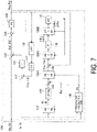
- rotation transformation according to the phase angle estimated value ⁇ d may be performed on the d-axis magnetic flux reference estimated value ⁇ dr and the q-axis magnetic flux reference estimated value ⁇ qr to calculate an a-axis magnetic flux reference estimated value ⁇ ar and a b-axis magnetic flux reference estimated value ⁇ br, and the magnetic flux error that is a difference between the a-axis magnetic flux reference estimated value ⁇ ar and the a-axis magnetic flux estimated value ⁇ a and a difference between the b-axis magnetic flux reference estimated value ⁇ br and the b-axis magnetic flux estimated value ⁇ b may be calculated (refer to block 134A in FIG. 7 ).
- the calculation of the correction values in block 135 may be performed in the ⁇ coordinate system or in the dq-axis coordinate system.
- the correction values ⁇ a', ⁇ b' may be calculated by performing rotation transformation according to the phase angle estimated value ⁇ on the magnetic flux error to calculate the magnetic flux error in the ⁇ coordinate system (refer to block 136A in FIG. 7 ), calculating correction values ⁇ ', ⁇ ' in the ⁇ coordinate system in block 135, and performing rotation transformation according to the phase angle estimated value ⁇ on the correction values ⁇ ', ⁇ ' (refer to block 136B in FIG. 7 ).
- the coordinate transformations of block 136A and block 136B in FIG. 7 need only be performed using the phase angle estimated value ⁇ d (not illustrated).
- the magnetic flux estimation unit 130 multiplies the correction values ⁇ a', ⁇ b' by a correction gain AK and respectively adds the multiplication results to the a-axis magnetic flux differential value ⁇ a' and the b-axis magnetic flux differential value ⁇ b', as represented by block 137 and summing point 146. This corrects the a-axis magnetic flux differential value ⁇ a' and the b-axis magnetic flux differential value ⁇ b' so as to reduce the magnetic flux error described above.
- the magnetic flux estimation unit 130 calculates the a-axis magnetic flux estimated value ⁇ a and the b-axis magnetic flux estimated value ⁇ b by respectively integrating the corrected a-axis magnetic flux differential value ⁇ a' and b-axis magnetic flux differential value ⁇ b', as represented by block 138.
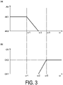
- the magnetic flux estimation unit 130 may gradually decrease the correction gain AK as the speed estimated value co increases. For example, as shown in FIG. 3(a) , when the speed estimated value co is less than or equal to a threshold value ⁇ 1, the magnetic flux estimation unit 130 sets the correction gain AK to a predetermined value AK1, and when the speed estimated value co is greater than or equal to a threshold value ⁇ 2, which is greater than the threshold value ⁇ 1, sets the correction gain AK to a predetermined value AK2 that is less than the predetermined value AK1. Further, as the speed estimated value approaches the threshold value ⁇ 2 from the threshold value ⁇ 1, the magnetic flux estimation unit 130 gradually changes the correction gain AK from the predetermined value AK1 to the predetermined value AK2.
- the estimation of the a-axis magnetic flux estimated value ⁇ a and the b-axis magnetic flux estimated value ⁇ b performed by the magnetic flux estimation unit 130 when the speed estimated value co is less than the threshold value ⁇ 2 corresponds to the first estimation described above.
- the estimation of the a-axis magnetic flux estimated value ⁇ a and the b-axis magnetic flux estimated value ⁇ b performed by the magnetic flux estimation unit 130 when the speed estimated value co exceeds the threshold value ⁇ 2 corresponds to the second estimation described above.
- the magnetic flux estimation unit 130 may stop correction of the magnetic flux differential value based on the output current and the inductance in the second estimation.
- the predetermined value AK2 may be zero. In this case, when the speed estimated value co exceeds the threshold value ⁇ 2, correction of the a-axis magnetic flux differential value ⁇ a' and the b-axis magnetic flux differential value ⁇ b' by the correction values ⁇ a', ⁇ b' is stopped.
- the magnetic flux estimation unit 130 calculates the a-axis magnetic flux differential value ⁇ a' and the b-axis magnetic flux differential value ⁇ b' without the values being based on the d-axis inductance Ld and the q-axis inductance Lq.
- the predetermined value AK2 may be greater than zero. In a case in which the predetermined value AK2 is greater than zero, in the second estimation, the correction of the magnetic flux differential value based on the output current and the inductance is performed at the correction gain AK that is less than the correction gain AK in the first estimation.
- the magnetic flux estimation unit 130 may remove, from the estimation result of the primary magnetic flux, a constant component that does not fluctuate in response to the operation of the electric motor 3.
- the magnetic flux estimation unit 130 in the removal of the constant component, may perform low-pass filtering on the estimation result of the primary magnetic flux, and remove the estimation result of the primary magnetic flux after the filtering (constant component extracted by the filtering) from the estimation result of the primary magnetic flux before the filtering.
- the magnetic flux estimation unit 130 performs low-pass filtering on the estimation results of the a-axis magnetic flux estimated value ⁇ a and the b-axis magnetic flux estimated value ⁇ b, multiplies the filtering results by a cancellation gain CK, and converts the constant components included in the primary magnetic flux estimation result into current correction values ⁇ Ia, ⁇ Ib.
- the magnetic flux estimation unit 130 adds the current correction values ⁇ Ia, ⁇ Ib to the a-axis current Ia and the b-axis current Ib immediately prior to input to block 131 (multiplication by the winding resistance r).
- the values obtained by multiplying the current correction values ⁇ Ia, ⁇ Ib by the winding resistance r are subtracted. Therefore, the cancellation values are removed from the a-axis magnetic flux estimated value ⁇ a and the b-axis magnetic flux estimated value ⁇ b calculated next.
- the cancellation values correspond to the a-axis magnetic flux estimated value ⁇ a and the b-axis magnetic flux estimated value ⁇ b after filtering, and thus removal of the cancellation values from the a-axis magnetic flux estimated value ⁇ a and b-axis magnetic flux estimated value ⁇ b calculated next corresponds to an example of removal of the a-axis magnetic flux estimated value ⁇ a and the b-axis magnetic flux estimated value ⁇ b after the filtering from the a-axis magnetic flux estimated value ⁇ a and the b-axis magnetic flux estimated value ⁇ b before the filtering.
- the filtering results may be subtracted from the a-axis magnetic flux differential value ⁇ a' and the b-axis magnetic flux differential value ⁇ b' or may be subtracted from the a-axis voltage command Va and the b-axis voltage command Vb.
- the magnetic flux estimation unit 130 may gradually increase the cancellation gain CK as the speed estimated value co increases.
- the magnetic flux estimation unit 130 may make the cancellation gain CK in the second estimation greater than the cancellation gain CK in the first estimation.
- the magnetic flux estimation unit 130 sets the cancellation gain CK to a predetermined value CK1, and when the speed estimated value co is greater than or equal to a threshold value ⁇ 3, which is greater than the threshold value ⁇ 2, sets the cancellation gain CK to a predetermined value CK2 that is greater than the predetermined value CK1. Further, as the speed estimated value approaches the threshold value ⁇ 3 from the threshold value ⁇ 2, the magnetic flux estimation unit 130 gradually changes the cancellation gain CK from the predetermined value CK1 to the predetermined value CK2.
- the magnetic flux estimation unit 130 may stop removal of the constant component in at least a portion of a period in which the first estimation is performed.
- the predetermined value CK1 may be zero. In this case, when the speed estimated value ⁇ is less than the threshold value ⁇ 2, removal of the constant components from the a-axis magnetic flux estimated value ⁇ a and the b-axis magnetic flux estimated value ⁇ b is stopped.
- the predetermined value CK1 may be greater than zero. In a case in which the predetermined value CK1 is greater than zero, in the first estimation, the constant component is removed at the cancellation gain CK that is less than the cancellation gain CK in the second estimation.
- the estimation processing of the primary magnetic flux exemplified above is merely an example. As long as the contribution of the output current and the inductance in the second estimation is small compared to the contribution of the output current and the inductance in the first estimation, and the integration in the second estimation is performed using the estimation result of the primary magnetic flux by the first estimation as the initial value, the estimation processing of the primary magnetic flux can be changed appropriately.
- the primary magnetic flux may be estimated on the basis of the output current and inductance without integration of the magnetic flux differential value.
- the magnetic flux estimation unit 130 may calculate the a-axis magnetic flux estimated value ⁇ a and the b-axis magnetic flux estimated value ⁇ b by performing rotation transformation according to the phase angle estimated value ⁇ d on the d-axis magnetic flux reference estimated value ⁇ dr and the q-axis magnetic flux reference estimated value ⁇ qr.
- the magnetic flux estimation unit 130 may calculate the a-axis magnetic flux estimated value ⁇ a and the b-axis magnetic flux estimated value ⁇ b by performing rotation transformation according to the phase angle estimated value ⁇ d on the d-axis magnetic flux reference estimated value ⁇ dr and the q-axis magnetic flux reference estimated value ⁇ qr.
- the electric motor 3 may be an induction electric motor.
- the d-axis magnetic flux reference estimated value ⁇ dr and the q-axis magnetic flux reference estimated value ⁇ qr are calculated by performing rotation transformation according to the phase angle estimated value ⁇ d on the a-axis magnetic flux reference estimated value ⁇ ar and the b-axis magnetic flux reference estimated value ⁇ br.
- FIG. 4 is a block diagram illustrating an example of a hardware configuration of the control circuit 100.
- the control circuit 100 includes a processor 191, a memory 192, a storage 193, an I/O port 194, and a switching control circuit 195.
- the processor 191 may include a plurality of processing devices
- the memory 192 may include a plurality of memory devices
- the storage 193 may include a plurality of storage devices.
- the storage 193 includes a computer-readable storage medium such as a non-volatile semiconductor memory, for example.
- the storage 193 stores a program for causing the control circuit 100 to execute estimating a primary magnetic flux appearing in the electric motor 3 by the supply of driving power, estimating an electromagnetic force of the electric motor 3 on the basis of the estimation result of the primary magnetic flux and the output current, and controlling the power conversion circuit 10 on the basis of a deviation between the target magnetic flux and the estimation result of the primary magnetic flux and a deviation between the target electromagnetic force and an estimation result of the electromagnetic force.
- the program described above is configured to cause the control circuit 100 (magnetic flux estimation device) to execute, when a rotation speed (operating speed) of the electric motor 3 is less than a predetermined level, a first estimation of estimating the primary magnetic flux on the basis of an output current from the power conversion circuit 10 to the electric motor 3 and an inductance of the electric motor 3 and, when the rotation speed of the electric motor 3 exceeds a predetermined level, a second estimation of estimating the primary magnetic flux by estimating a magnetic flux differential value on the basis of an output voltage from the power conversion circuit 10 to the electric motor 3 and integrating the magnetic flux differential value using, as an initial value, an estimation result of the primary magnetic flux by the first estimation.
- the storage 193 stores a program for implementing each of the functional elements described above in the control circuit 100.
- the memory 192 temporarily stores programs loaded from the storage medium of the storage 193 and calculation results from the processor 191.
- the processor 191 implements each functional element of the control circuit 100 by executing the program described above in cooperation with the memory 192.
- the I/O port 194 inputs and outputs electric signals to and from the current sensor 14 in accordance with commands from the processor 191.
- the switching control circuit 195 outputs, to the inverter circuit 13, a drive signal for switching the plurality of switching elements 15 on and off in accordance with commands from the processor 191.
- control circuit 100 the functions are not limited to being implemented by a program.
- control circuit 100 may implement at least one function by a dedicated logic circuit or an application specific integrated circuit (ASIC) integrated therewith.
- ASIC application specific integrated circuit
- This procedure includes estimating a primary magnetic flux appearing in the electric motor 3 by the supply of driving power, estimating an electromagnetic force of the electric motor 3 on the basis of the estimation result of the primary magnetic flux and the output current, and controlling the power conversion circuit 10 on the basis of a deviation between the target magnetic flux and the estimation result of the primary magnetic flux and a deviation between the target electromagnetic force and an estimation result of the electromagnetic force.
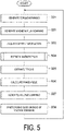
- the control circuit 100 sequentially executes steps S01, S02, S03, S04, S05, S06, S07, S08.
- step S01 the electromagnetic force command generation unit 110 generates the target electromagnetic force described above so as to cause the electric motor 3 to perform a desired operation.
- the electromagnetic force command generation unit 110 calculates the target torque Tt by calculating a speed deviation, which is a difference between the target speed cot and the speed estimated value co, and applying a proportional operation, a proportional/integration operation, a proportional/integration/differentiation operation, or the like to the speed deviation.
- step S02 the magnetic flux command generation unit 120 calculates the target magnetic flux ⁇ t described above on the basis of the target torque Tt and the inductance of the electric motor 3.
- step S03 the current information acquisition unit 101 acquires a detection result of the output current by the current sensor 14 and calculates the a-axis current Ia and the b-axis current Ib by performing three-phase to two-phase conversion on the acquired detection result.
- step S04 the magnetic flux estimation unit 130 estimates the primary magnetic flux appearing in the electric motor 3 by the supply of driving power. The specific content of step S04 will be described later.
- step S05 the electromagnetic force estimation unit 150 estimates the torque (electromagnetic force) of the electric motor 3 on the basis of the estimation result of the primary magnetic flux and the output current.
- step S06 the phase angle calculation unit 170 calculates the speed estimated value co and the phase angle estimated value ⁇ by inputting the a-axis magnetic flux estimated value ⁇ a and the b-axis magnetic flux estimated value ⁇ b into a phase locked loop.
- step S07 the voltage command generation unit 160 generates a voltage command so as to reduce the deviation between the target magnetic flux ⁇ t and the primary magnetic flux estimated value ⁇ and reduce the deviation between the target torque Tt and the torque estimated value T.
- step S08 the PWM control unit 180 starts turning the plurality of switching elements 15 of the inverter circuit 13 on and off so as to generate a voltage according to the voltage command generated by the voltage command generation unit 160.
- the PWM control unit 180 calculates the a-axis voltage command Va and the b-axis voltage command Vb by performing rotation transformation according to the phase angle estimated value ⁇ on the d-axis voltage command Vd and the q-axis voltage command Vq, calculates the phase voltage command of the driving power by performing two-phase to three-phase conversion on the a-axis voltage command Va and the b-axis voltage command Vb, and starts turning the plurality of switching elements 15 on and off on the basis of the phase voltage command.
- the control circuit 100 repeatedly executes the processing described above.
- the speed estimated value co calculated in step S06 is used to calculate the speed deviation in step S01 of the next cycle, and used to generate the voltage command in step S07 of the next cycle. Further, the a-axis voltage command Va and the b-axis voltage command Vb calculated in step S08 are used to estimate the primary magnetic flux in step S04 of the next cycle. Furthermore, the speed estimated value ⁇ and the phase angle estimated value ⁇ calculated in step S06 are also used to estimate the primary magnetic flux in step S04 of the next cycle.
- This procedure includes performing, when the operating speed of the electric motor 3 is less than a predetermined level, the first estimation of estimating the primary magnetic flux appearing in the electric motor 3 on the basis of an output current from the power conversion circuit 10 to the electric motor 3 and an inductance of the electric motor 3, and performing, when the operating speed exceeds a predetermined level, the second estimation of estimating the primary magnetic flux by estimating a magnetic flux differential value on the basis of an output voltage from the power conversion circuit 10 to the electric motor 3 and integrating the magnetic flux differential value using, as an initial value, an estimation result of the primary magnetic flux by the first estimation.
- the calculation of the correction values ⁇ a', ⁇ b' is continued even in a period in which the correction gain AK is zero, but the calculation itself of the correction values ⁇ a', ⁇ b' may be stopped in the period in which the correction gain AK is zero. Further, according to the block diagram of FIG. 2 , the calculation of the current correction values ⁇ Ia, ⁇ Ib is continued even in a period in which the cancellation gain CK is zero, but the calculation itself of the current correction values ⁇ Ia, ⁇ Ib may be stopped in the period in which the cancellation gain CK is zero.
- step S11 the magnetic flux estimation unit 130 checks whether the operating speed (for example, the speed estimated value ⁇ calculated in the previous step S06) is greater than or equal to the threshold value ⁇ 2 described above.
- step S12 the magnetic flux estimation unit 130 calculates the a-axis magnetic flux differential value ⁇ a' and the b-axis magnetic flux differential value ⁇ b' by multiplying the a-axis current Ia and the b-axis current Ib calculated in step S03 by the winding resistance r to calculate a voltage drop in the winding, and subtracting the voltage drop from the a-axis voltage command Va and the b-axis voltage command Vb (a-axis voltage command Va and b-axis voltage command Vb calculated in step S08 of the previous cycle).
- step S13 the magnetic flux estimation unit 130 performs a reference estimation of the primary magnetic flux on the basis of the a-axis current Ia and the b-axis current Ib, the d-axis inductance Ld and the q-axis inductance Lq, and the magnetic flux ⁇ m of the magnets, and calculates the d-axis magnetic flux reference estimated value ⁇ dr and the q-axis magnetic flux reference estimated value ⁇ qr described above.
- the magnetic flux estimation unit 130 calculates the d-axis magnetic flux estimated value ⁇ d and the q-axis magnetic flux estimated value ⁇ q by performing rotation transformation according to the phase angle estimated value ⁇ d on the a-axis magnetic flux estimated value ⁇ a and the b-axis magnetic flux estimated value ⁇ b, and calculates the magnetic flux error that is the difference between the d-axis magnetic flux reference estimated value ⁇ dr and the d-axis magnetic flux estimated value ⁇ d, and the difference between the q-axis magnetic flux reference estimated value ⁇ qr and the q-axis magnetic flux estimated value ⁇ q.
- the correction values ⁇ d', ⁇ q' are calculated by applying a proportional operation, proportional/integration operation, a proportional/integration/differentiation operation, or the like to the magnetic flux error.
- the magnetic flux estimation unit 130 calculates the correction gain AK on the basis of the speed estimated value ⁇ .
- the magnetic flux estimation unit 130 corrects the a-axis magnetic flux differential value ⁇ a' and the b-axis magnetic flux differential value ⁇ b' calculated in step S12 by adding the values obtained by multiplying the correction values ⁇ a', ⁇ b' by the correction gain AK
- step S11 the control circuit 100 executes steps S21, S22, S23, S24, S25.
- step S21 the magnetic flux estimation unit 130 calculates the constant components of the a-axis magnetic flux estimated value ⁇ a and the b-axis magnetic flux estimated value ⁇ b by performing low-pass filtering on the a-axis magnetic flux estimated value ⁇ a and the b-axis magnetic flux estimated value ⁇ b calculated in the previous cycle.
- step S22 the magnetic flux estimation unit 130 calculates the cancellation gain CK on the basis of the operating speed.
- step S23 the magnetic flux estimation unit 130 corrects the a-axis current Ia and the b-axis current Ib calculated in step S03 by multiplying the constant components by the cancellation gain CK to calculate the current correction values ⁇ Ia, ⁇ Ib and adding the current correction values ⁇ Ia, ⁇ Ib to the a-axis current Ia and the b-axis current Ib.
- step S24 the magnetic flux estimation unit 130 calculates the a-axis magnetic flux differential value ⁇ a' and the b-axis magnetic flux differential value ⁇ b' by multiplying the a-axis current Ia and the b-axis current Ib calculated in step S23 by the winding resistance r to calculate a voltage drop in the winding, and subtracting the voltage drop from the a-axis voltage command Va and the b-axis voltage command Vb (a-axis voltage command Va and b-axis voltage command Vb calculated in step S08 of the previous cycle).
- step S25 the magnetic flux estimation unit 130, as represented by block 138, calculates the a-axis magnetic flux estimated value ⁇ a and the b-axis magnetic flux estimated value ⁇ b by respectively integrating the a-axis magnetic flux differential value ⁇ a' and the b-axis magnetic flux differential value ⁇ b'.
- the magnetic flux estimation procedure in step S04 is completed.
- control device 1 includes the power conversion circuit 10 configured to supply driving power to the electric motor 3, the magnetic flux estimation unit 130 configured to estimate a primary magnetic flux appearing in the electric motor 3 by the supply of the driving power, and the voltage command generation unit 160 (control unit) configured to control the power conversion circuit 10 on the basis of an estimation result of the primary magnetic flux by the magnetic flux estimation unit 130.
- the magnetic flux estimation unit 130 performs, when the operating speed of the electric motor 3 is less than a predetermined level, a first estimation of estimating the primary magnetic flux on the basis of an output current from the power conversion circuit 10 to the electric motor 3 and an inductance of the electric motor 3, and performs, when the operating speed exceeds a predetermined level, a second estimation of estimating the primary magnetic flux by estimating a magnetic flux differential value on the basis of an output voltage from the power conversion circuit 10 to the electric motor 3 and integrating the magnetic flux differential value using, as an initial value, an estimation result of the primary magnetic flux by the first estimation.
- the primary magnetic flux can be estimated with high accuracy. Nevertheless, the estimation result of the first estimation has low robustness against inductance fluctuation due to magnetic flux saturation of the electric motor 3. Further, the estimation result of the first estimation becomes more susceptible to inductance fluctuation as the operating speed of the electric motor 3 increases.
- the second estimation of estimating the primary magnetic flux by estimating the magnetic flux differential value on the basis of the output voltage and integrating the magnetic flux differential value the dependency on inductance in the estimation of the primary magnetic flux is extremely small, and thus the robustness against inductance fluctuation is high.
- the estimation accuracy of the magnetic flux differential value decreases as the operating speed of the electric motor 3 decreases and the output voltage accuracy of the power conversion circuit 10 decreases. Therefore, for example, the estimation error of the magnetic flux differential value accumulates by integration in a low-speed range after activation of the electric motor 3, and the accumulated estimation error remains even after a high-speed range in which the estimation accuracy of the magnetic flux differential value is sufficiently high is reached. Therefore, even with the second estimation only, it is difficult to estimate the primary magnetic flux with high accuracy.
- the first estimation suitable for the low-speed range is performed and, when the operating speed of the electric motor 3 exceeds the predetermined level, the second estimation suitable for the high-speed range is performed.
- the magnetic flux differential value is integrated using the estimation result of the primary magnetic flux by the first estimation as an initial value, and thus the effect of the estimation error of the magnetic flux differential value in the low-speed range is unlikely to remain in the estimation result of the high-speed range. Accordingly, this is effective in improving the reliability of the control of the power conversion circuit 10 based on the primary magnetic flux.
- the magnetic flux estimation unit 130 may calculate the primary magnetic flux by calculating the magnetic flux differential value on the basis of the output voltage, correcting the magnetic flux differential value on the basis of the output current and the inductance, and integrating the magnetic flux differential value after correction.
- a voltage model method of integrating the magnetic flux differential value based on the output voltage to calculate the primary magnetic flux is used as a base, and the magnetic flux differential value is corrected on the basis of the output current and the inductance, making it possible to smoothly change from the first estimation to the second estimation and change from the second estimation to the first estimation.
- the magnetic flux estimation unit 130 in the first estimation, may reduce correction of the magnetic flux differential value based on the output current and the inductance in response to the operating speed approaching a predetermined level. In this case, the change from the first estimation to the second estimation can be performed more smoothly.
- the magnetic flux estimation unit 130 may repeatedly execute the first estimation and, in each of the first estimations, calculate the magnetic flux differential value on the basis of the output voltage, perform a reference estimation of estimating the primary magnetic flux on the basis of the output current and the inductance, calculate a correction value on the basis of a deviation between an estimation result of the primary magnetic flux by a previous first estimation and an estimation result of the primary magnetic flux by the reference estimation, and correct the magnetic flux differential value on the basis of the correction value.
- correction of the magnetic flux differential value based on the output current and the inductance can be easily and accurately performed.
- the magnetic flux estimation unit 130 may stop correction of the magnetic flux differential value based on the output current and the inductance in the second estimation. In this case, the robustness of the estimation result of the primary magnetic flux can be further improved.
- the magnetic flux estimation unit 130 may remove, from the estimation result of the primary magnetic flux, a constant component that does not fluctuate in response to the operation of the electric motor 3. In this case, both the accuracy and the robustness of the estimation result of the primary magnetic flux can be further improved in a compatible manner.
- the magnetic flux estimation unit 130 may stop removal of the constant component in at least a portion of a period in which the first estimation is performed. In this case, an operation load can be suppressed.
- the magnetic flux estimation unit 130 in the removal of the constant component, may perform low-pass filtering on the estimation result of the primary magnetic flux, and remove the estimation result of the primary magnetic flux after the filtering from the estimation result of the primary magnetic flux before the filtering. In this case, removal of the constant component can be easily performed.
- the control device 1 may further include the electromagnetic force estimation unit 150 configured to estimate an electromagnetic force of the electric motor 3 on the basis of the estimation result of the primary magnetic flux and the output current, and the voltage command generation unit 160 may be configured to control the power conversion circuit 10 on the basis of a deviation between a target magnetic flux and the estimation result of the primary magnetic flux and a deviation between a target electromagnetic force and an estimation result of the electromagnetic force.
- the estimation result of the primary magnetic flux can be effectively utilized in electromagnetic force control.
- the control device 1 may further include the magnetic flux command generation unit 120 configured to calculate the target magnetic flux on the basis of the target electromagnetic force and the inductance.
- the electromagnetic force can be easily and appropriately controlled.
Landscapes
- Engineering & Computer Science (AREA)
- Power Engineering (AREA)
- Control Of Ac Motors In General (AREA)
Abstract
Description
- The present disclosure relates to a control device, a magnetic flux estimation device, and a magnetic flux estimation method.
-
Patent Document 1 discloses a control device configured to smoothly change a stator magnetic flux calculation model from a current model to a voltage model on the basis of a rotor speed. - Patent Document 1:
JP 2007-525137 T - The present disclosure provides a power conversion device effective in improving a reliability of electric motor control based on an estimation result of a primary magnetic flux.
- A control device according to an aspect of the present disclosure includes a power conversion circuit configured to supply driving power to an electric motor, a magnetic flux estimation unit configured to estimate a primary magnetic flux appearing in the electric motor by the supply of the driving power, and a control unit configured to control the power conversion circuit on the basis of an estimation result of the primary magnetic flux by the magnetic flux estimation unit. The magnetic flux estimation unit performs, when an operating speed of the electric motor is less than a predetermined level, a first estimation of estimating the primary magnetic flux on the basis of an output current from the power conversion circuit to the electric motor and an inductance of the electric motor, and performs, when the operating speed exceeds a predetermined level, a second estimation of estimating the primary magnetic flux by estimating a magnetic flux differential value on the basis of an output voltage from the power conversion circuit to the electric motor and integrating the magnetic flux differential value using, as an initial value, an estimation result of the primary magnetic flux by the first estimation.
- A magnetic flux estimation device according to another aspect of the present disclosure is configured to perform, when an operating speed of an electric motor is less than a predetermined level, a first estimation of estimating a primary magnetic flux appearing in the electric motor on the basis of an output current from a power conversion circuit to the electric motor and an inductance of the electric motor, and perform, when the operating speed exceeds a predetermined level, a second estimation of estimating the primary magnetic flux by estimating a magnetic flux differential value on the basis of an output voltage from the power conversion circuit to the electric motor and integrating the magnetic flux differential value using, as an initial value, an estimation result of the primary magnetic flux by the first estimation.
- A magnetic flux estimation method according to yet another aspect of the present disclosure includes performing, when an operating speed of an electric motor is less than a predetermined level, a first estimation of estimating a primary magnetic flux appearing in the electric motor on the basis of an output current from a power conversion circuit to the electric motor and an inductance of the electric motor, and performing, when the operating speed exceeds a predetermined level, a second estimation of estimating the primary magnetic flux by estimating a magnetic flux differential value on the basis of an output voltage from the power conversion circuit to the electric motor and integrating the magnetic flux differential value using, as an initial value, an estimation result of the primary magnetic flux by the first estimation.
- According to the present disclosure, it is possible to provide a power conversion device effective in improving a reliability of electric motor control based on an estimation result of a primary magnetic flux.
-
-
FIG. 1 is a schematic view illustrating an example of a configuration of a control device. -
FIG. 2 is a block diagram illustrating an example of a functional configuration of a magnetic flux estimation unit. -
FIG. 3 are graphs showing setting examples of a correction gain and a cancellation gain. -
FIG. 4 is a block diagram illustrating an example of a hardware configuration of a control circuit. -
FIG. 5 is a flowchart illustrating an example of a control procedure. -
FIG. 6 is a flowchart illustrating an example of a magnetic flux estimation procedure. -
FIG. 7 is a block diagram illustrating a modified example of the magnetic flux estimation unit. - An embodiment will be described in detail below with reference to the drawings. In the description, elements which are the same or have the same function are given the same reference numbers, and redundant descriptions thereof are omitted.
- A
control device 1 illustrated inFIG. 1 is a device configured to control anelectric motor 3. Thecontrol device 1 converts power supplied from a power source 2 into driving power and supplies the driving power to theelectric motor 3. The power source 2 may be a direct current power source or an alternating current power source. As an example,FIG. 1 illustrates a case in which the power source 2 is a three-phase alternating current power source. Specific examples of the three-phase alternating current power source include a power system of an electric power company, a three-phase alternating current generator, and an uninterruptible power source. - The
electric motor 3 is an alternating current electric motor that operates by the supply of alternating current driving power (for example, three-phase alternating current power). Theelectric motor 3 may be a synchronous electric motor. For example, theelectric motor 3 is a permanent magnet assistance (PMA) motor. Theelectric motor 3 may be an interior permanent magnet (IPM) motor, or may be a surface permanent magnet (SPM) motor. Theelectric motor 3 may be a synchronous reluctance motor with no permanent magnets. Theelectric motor 3 may be an induction electric motor. - The
electric motor 3 may be a fixed coil type provided with a coil in the stator, or may be a movable coil type provided with a coil in a movable element. Further, theelectric motor 3 may be a rotating type or may be a linear type. - The
control device 1 includes apower conversion circuit 10 and acontrol circuit 100. Thepower conversion circuit 10 converts power supplied from the power source 2 (hereinafter referred to as "source power") to driving power and supplies the driving power to theelectric motor 3. As an example, thepower conversion circuit 10 includes arectifier circuit 11, asmoothing capacitor 12, aninverter circuit 13, and acurrent sensor 14. Therectifier circuit 11 is, for example, a diode bridge circuit or a pulse width modulation (PWM) converter circuit, and converts the source power described above to direct current power. Thesmoothing capacitor 12 smooths the direct current power described above. - The
inverter circuit 13 performs power conversion between the direct current power described above and the driving power described above. For example, theinverter circuit 13 converts the direct current power to the driving power and supplies the driving power to theelectric motor 3 in a powering state, and converts the power generated by theelectric motor 3 into direct current power in a regeneration state. Note that the powering state is a state in which theelectric motor 3 operates by the driving power supplied from theinverter circuit 13, and the regeneration state is a state in which theelectric motor 3 supplies power generated in accordance with operation to theinverter circuit 13. - For example, the
inverter circuit 13 includes a plurality ofswitching elements 15, and performs the power conversion described above by switching the plurality of switchingelements 15 on and off. Each of theswitching elements 15 is, for example, a power metal-oxide-semiconductor field-effect transistor (MOSFET) or an insulated gate bipolar transistor (IGBT), and is switched on and off in accordance with a gate drive signal. - The
current sensor 14 detects a current flowing between theinverter circuit 13 and the electric motor 3 (hereinafter referred to as "output current"). For example, thecurrent sensor 14 may be configured to detect the currents of all phases of the three-phase alternating current (U phase, V phase, and W phase), or may be configured to detect the currents of any two phases of the three-phase alternating current. A sum of the currents of the U phase, V phase, and W phase is zero except in a case in which a zero phase current occurs, and thus the information of the currents of all phases can be acquired even in a case in which the currents of two phases are detected. - The configuration of the
power conversion circuit 10 illustrated above is merely an example. The configuration of thepower conversion circuit 10 can be modified as long as the driving power of theelectric motor 3 can be generated. For example, therectifier circuit 11 may be a PWM converter that converts alternating current power to direct current power or a matrix converter circuit. Thepower conversion circuit 10 may be a matrix converter circuit that performs bidirectional power conversion between the source power and the driving power without direct current conversion. In a case in which the source power is direct current power, thepower conversion circuit 10 need not include therectifier circuit 11. - The
control circuit 100 controls thepower conversion circuit 10 such that the driving power according to a control command is supplied to theelectric motor 3. Thecontrol circuit 100 controls thepower conversion circuit 10 on the basis of an estimation result of a primary magnetic flux. More specifically, thecontrol circuit 100 is configured to estimate a primary magnetic flux appearing in theelectric motor 3 by the supply of the driving power, estimate an electromagnetic force of theelectric motor 3 on the basis of the estimation result of the primary magnetic flux and the output current (current detected by the current sensor 14), and control thepower conversion circuit 10 on the basis of a deviation between a target magnetic flux and the estimation result of the primary magnetic flux and a deviation between a target electromagnetic force and an estimation result of the electromagnetic force. Therefore, thecontrol circuit 100 includes a magnetic flux estimation device that estimates the primary magnetic flux described above. - For example, the
control circuit 100 includes, as functional elements, an electromagnetic forcecommand generation unit 110, a magnetic fluxcommand generation unit 120, a currentinformation acquisition unit 101, a magneticflux estimation unit 130, an electromagneticforce estimation unit 150, a voltagecommand generation unit 160, a phaseangle calculation unit 170, and aPWM control unit 180. - The electromagnetic force
command generation unit 110 generates the target electromagnetic force described above so as to cause theelectric motor 3 to perform a desired operation. The "electromagnetic force" need only be a value correlating to force applied by theelectric motor 3 to the driven object. In a case in which theelectric motor 3 is a rotating type, the electromagnetic force may be a torque appearing in theelectric motor 3 around an axis of rotation. In a case in which theelectric motor 3 is a linear type, the electromagnetic force may be thrust force produced in a movement direction of the movable element by theelectric motor 3. - As an example, the electromagnetic force
command generation unit 110 calculates a speed deviation, which is a difference between a target speed cot and a speed estimated value co, as represented by summingpoint 111. The target speed cot is, for example, a target value of an angular speed of an electrical angle, and the speed estimated value co is an estimated value of the angular speed of the electrical angle. The electromagnetic forcecommand generation unit 110 may acquire the target speed cot stored in advance by thecontrol circuit 100, or may acquire the target speed cot from an upper controller such as a programmable logic controller. The electromagnetic forcecommand generation unit 110 calculates a target torque Tt (target electromagnetic force) by applying a proportional operation, proportional/integration operation, a proportional/integration/differentiation operation, or the like to the speed deviation, as represented byblock 112. - The magnetic flux
command generation unit 120 calculates a target primary magnetic flux Φt described above on the basis of the target torque Tt, the magnetic flux of the magnets of theelectric motor 3, and the inductance of theelectric motor 3. For example, when theelectric motor 3 is a synchronous electric motor other than a synchronous reluctance electric motor, the magnetic fluxcommand generation unit 120 calculates a target current on the basis of the target torque Tt, and calculates the target primary magnetic flux Φt according to the following equation:


- Φdt: d-axis primary magnetic flux target value
- Φqt: q-axis primary magnetic flux target value
- Ld: d-axis inductance
- Lq: q-axis inductance
- Idt: d-axis current target value
- Iqt: q-axis current target value
- Φm: Magnetic flux of magnets
- In a case in which the
electric motor 3 is a synchronous reluctance electric motor, the magnetic flux Φm of the magnets in equation (1) is zero. In a case in which theelectric motor 3 is an induction electric motor, the d-axis inductance Ld is replaced by the primary inductance L1. The q-axis inductance Lq is replaced by a leakage inductance corresponding to a sum of aprimary leakage inductance 11 and asecondary leakage inductance 12. - The d axis and the q axis are coordinate axes of a dq coordinate system, which is a rotating coordinate system, and are respectively perpendicular to the axis of rotation of the
electric motor 3. In a case in which theelectric motor 3 is a PMA, the d axis, for example, is in a direction of the magnetic flux of the magnets, and the q axis is perpendicular to the direction of the magnetic flux of the magnets. An origin at which the d axis and the q axis meet is positioned at a center of rotation of theelectric motor 3. In a case in which theelectric motor 3 is an induction electric motor, the d axis is, for example, oriented toward a direction of a gap magnetic flux, and the q axis is perpendicular to the direction of the gap magnetic flux. In a case in which theelectric motor 3 is a synchronous reluctance electric motor, the d axis is in a salient pole direction of the rotor, and the q axis is perpendicular to the salient pole direction. Further, in a case in which theelectric motor 3 is a synchronous reluctance electric motor, the d axis and the q axis are coordinate axes of the dq coordinate system that rotates with the salient poles of the rotor, and the d axis is in the salient pole direction. - The d-axis magnetic flux is a d-axis component of the primary magnetic flux, and the q-axis magnetic flux is a q-axis component of the primary magnetic flux. The d-axis current is a current that generates magnetic flux along the d axis and the q-axis current is a current that generates magnetic flux along the q axis. The d-axis inductance is a coefficient for determining the d-axis magnetic flux from the d-axis current, and the q-axis inductance is a coefficient for determining the q-axis magnetic flux from the q-axis current.
- The current
information acquisition unit 101 acquires a detection result of the output current by thecurrent sensor 14, and performs three-phase to two-phase conversion on the acquired detection result to calculate an a-axis current Ia and a b-axis current Ib. The a-axis current Ia is an a-axis component of the output current, and the b-axis current Ib is a b-axis component of the output current. - The a axis and the b axis are coordinate axes of an ab coordinate system, which is a fixed coordinate system, and are each perpendicular to the axis of rotation of the
electric motor 3. The a axis and the b axis are perpendicular to each other, and an origin at which the a axis and the b axis meet coincides with a center of rotation of theelectric motor 3. - The magnetic
flux estimation unit 130 estimates the primary magnetic flux appearing in theelectric motor 3 by the supply of driving power. For example, the magneticflux estimation unit 130 calculates a primary magnetic flux estimated value Φ, an a-axis primary magnetic flux estimated value Φa, and a b-axis primary magnetic flux estimated value Φb. The a-axis magnetic flux is an a-axis component of the primary magnetic flux, and the b-axis magnetic flux is a b-axis component of the primary magnetic flux. The estimation processing of the primary magnetic flux by the magneticflux estimation unit 130 will be described later. - The electromagnetic
force estimation unit 150 estimates the torque (electromagnetic force) of theelectric motor 3 on the basis of the estimation result of the primary magnetic flux and the output current. For example, the electromagneticforce estimation unit 150 calculates a torque estimated value T according to the following equation:
- The voltage command generation unit 160 (control unit) controls the
power conversion circuit 10 on the basis of the estimation result of the primary magnetic flux by the magneticflux estimation unit 130. For example, the voltagecommand generation unit 160 controls thepower conversion circuit 10 on the basis of the deviation between the target magnetic flux and the estimation result of the primary magnetic flux and the deviation between the target electromagnetic force and the estimation result of the electromagnetic force. - As an example, the voltage
command generation unit 160 generates a voltage command so as to reduce the deviation between the target magnetic flux Φt and the primary magnetic flux estimated value Φ and reduce the deviation between the target torque Tt and the torque estimated value T. For example, the voltagecommand generation unit 160 generates a voltage command in a γδ coordinate system that rotates with the primary magnetic flux. The γ axis and the δ axis, which are coordinate axes of the γδ coordinate system, are each perpendicular to the axis of rotation of theelectric motor 3. An origin at which the γ axis and the δ axis meet is positioned at the center of rotation of theelectric motor 3. The γ axis is oriented toward the direction of the primary magnetic flux, and the δ axis is perpendicular to the direction of the primary magnetic flux. For example, the voltagecommand generation unit 160 calculates a γ-axis voltage command Vγ by calculating a magnetic flux deviation, which is the difference between the target magnetic flux Φt and the primary magnetic flux estimated value Φ, as represented by summingpoint 161, and applying a proportional operation, a proportional/integration operation, a proportional/integration/differentiation operation, or the like on the magnetic flux deviation, as represented byblock 162. The γ-axis voltage command Vy is a γ-axis component of the voltage command. - Further, the voltage
command generation unit 160 calculates a torque control voltage by calculating a torque deviation, which is a difference between the target torque Tt and the torque estimated value T, as represented by summingpoint 163, dividing the torque deviation by the primary magnetic flux estimated value Φ, as represented byblock 164, and applying a proportional operation, a proportional/integration operation, or a proportional/integration/differentiation operation on the division result, as represented byblock 165. - Furthermore, the voltage
command generation unit 160 calculates an induced voltage by multiplying the primary magnetic flux estimated value Φ by the speed estimated value ω, as represented byblock 166. Then, the voltagecommand generation unit 160 calculates a δ-axis voltage command Yδ by adding the induced voltage to the torque control voltage, as represented by summingpoint 167. The δ-axis voltage command V8 is a δ-axis component of the voltage command. - The phase
angle calculation unit 170 calculates the speed estimated value ω and the phase angle estimated value θ by inputting the a-axis magnetic flux estimated value Φa and the b-axis magnetic flux estimated value Φb into a phase locked loop. The speed estimated value ω is an estimated value of a rotation speed of the primary magnetic flux, and the phase angle estimated value θ is an estimated value of a rotational angle of the primary magnetic flux. The speed estimated value ω calculated by the phaseangle calculation unit 170 is fed back to the electromagnetic forcecommand generation unit 110, and used to calculate the target torque Tt described above. Further, the speed estimated value ω calculated by the phaseangle calculation unit 170 is also used to calculate the induced voltage described above in the voltagecommand generation unit 160. - The
PWM control unit 180 controls thepower conversion circuit 10 such that a voltage according to the voltage command generated by the voltagecommand generation unit 160 is generated. For example, thePWM control unit 180 calculates a phase voltage command for the driving power by performing rotation transformation according to the phase angle estimated value θ on the γ-axis voltage command Vy and the δ-axis voltage command Vδ to calculate an a-axis voltage command Va and a b-axis voltage command Vb, and performing a two-phase to three-phase conversion on the a-axis voltage command Va and the b-axis voltage command Vb. ThePWM control unit 180 switches the plurality of switchingelements 15 of theinverter circuit 13 on and off such that the three-phase alternating current voltage according to the phase voltage command is applied to theelectric motor 3. - In this way, the
power conversion circuit 10 is controlled so as to generate a voltage according to the voltage command generated by the voltagecommand generation unit 160, and thus thepower conversion circuit 10 is controlled on the basis of the deviation between the target magnetic flux and the estimation result of the primary magnetic flux and the deviation between the target electromagnetic force and the estimation result of the electromagnetic force. - In the following, the estimation processing of the primary magnetic flux by the magnetic
flux estimation unit 130 will be specifically exemplified. The magneticflux estimation unit 130 is configured to perform, when an operating speed of theelectric motor 3 is less than a predetermined level, a first estimation of estimating the primary magnetic flux on the basis of an output current from thepower conversion circuit 10 to theelectric motor 3 and an inductance of theelectric motor 3, and perform, when the operating speed of theelectric motor 3 exceeds a predetermined level, a second estimation of estimating the primary magnetic flux by estimating a magnetic flux differential value on the basis of an output voltage from thepower conversion circuit 10 to theelectric motor 3 and integrating the magnetic flux differential value using, as an initial value, an estimation result of the primary magnetic flux by the first estimation. Note that the operating speed may be a frequency command (speed command in the case of a synchronous electric motor) or may be a speed estimated value. - In the first estimation, the magnetic
flux estimation unit 130 need only estimate the primary magnetic flux on the basis of at least the output current and the inductance, and may further estimate the primary magnetic flux on the basis of the output voltage as well. For example, the magneticflux estimation unit 130, in the first estimation, may calculate the primary magnetic flux by calculating the magnetic flux differential value on the basis of the output voltage, correcting the magnetic flux differential value on the basis of the output current and the inductance, and integrating the magnetic flux differential value after correction. - The magnetic
flux estimation unit 130 may, when the operating speed of theelectric motor 3 is less than the predetermined level, repeatedly execute the first estimation and, in each of the first estimations, calculate the magnetic flux differential value on the basis of the output voltage, perform a reference estimation of estimating the primary magnetic flux on the basis of the output current and the inductance, calculate a correction value on the basis of a deviation between an estimation result of the primary magnetic flux by a previous first estimation and an estimation result of the primary magnetic flux by the reference estimation, and correct the magnetic flux differential value on the basis of the correction value. - The magnetic
flux estimation unit 130, in the first estimation, may reduce correction of the magnetic flux differential value based on the output current and the inductance in response to the operating speed approaching a predetermined level. "Reduce correction" means reducing the degree to which the correction value calculated on the basis of the output current and the inductance is reflected in the magnetic flux differential value. As an example, the magneticflux estimation unit 130 calculates the correction value on the basis of a value obtained by multiplying the correction value calculated on the basis of the output current and the inductance by a correction gain, and reduces the correction gain in response to the operating speed approaching the predetermined level. - The magnetic
flux estimation unit 130 may use the a-axis voltage command Va and the b-axis voltage command Vb as the output voltage described above. The magneticflux estimation unit 130 may use the voltage detected value from the sensor as the output voltage described above. Further, the magneticflux estimation unit 130 may use the a-axis current Ia and the b-axis current Ib as the output current described above. -
FIG. 2 is a block diagram illustrating an example of a functional configuration of the magneticflux estimation unit 130 in a case in which theelectric motor 3 is a synchronous electric motor. The magneticflux estimation unit 130 calculates the magnetic flux differential value by multiplying the a-axis current Ia and the b-axis current Ib by a winding resistance r to calculate a voltage drop in the winding as represented byblock 131, and subtracting the voltage drop from the a-axis voltage command Va and the b-axis voltage command Vb as represented by summingpoint 143. For example, the magneticflux estimation unit 130 calculates the magnetic flux differential value according to the following equation:

- Φa': a-axis magnetic flux differential value
- Φb': b-axis magnetic flux differential value
- r: winding resistance
- The magnetic
flux estimation unit 130 calculates a d-axis current Id and a q-axis current Iq by performing rotation transformation on the a-axis current Ia and the b-axis current Ib, as represented byblock 132. The d-axis current Id is a d-axis component of the output current, and the q-axis current Iq is a q-axis component of the output current. - To convert the a-axis current Ia and the b-axis current Ib to the d-axis current Id and the q-axis current Iq, the magnetic
flux estimation unit 130 calculates a phase angle estimated value θd of the dq coordinate system with respect to the ab coordinate system on the basis of the a-axis current Ia, the b-axis current Ib, the a-axis voltage command Va, and the b-axis voltage command Vb, as represented byblock 148. For example, the magneticflux estimation unit 130 calculates the phase angle estimated value θd by an extended induced voltage observer. More specifically, the magneticflux estimation unit 130 calculates, by a phase locked loop, the phase angle estimated value θd so that the d-axis component of the induced voltage in the dq coordinate system is zero. Note that the induced voltage in the dq coordinate system is calculated on the basis of the d-axis current Id and the q-axis current Iq obtained by performing rotation transformation according to the phase angle estimated value θd on the a-axis current Ia and the b-axis current Ib, and a d-axis voltage command Vd and a q-axis voltage command Vq obtained by performing rotation transformation according to the phase angle estimated value θd on the a-axis voltage command Va and the b-axis voltage command Vb. - Furthermore, the magnetic
flux estimation unit 130 performs a reference estimation of the primary magnetic flux on the basis of the d-axis current Id and the q-axis current Iq, the d-axis inductance Ld and the q-axis inductance Lq, and the magnetic flux Φm of the magnets (zero in a case in which theelectric motor 3 is a synchronous reluctance electric motor), as represented byblock 133 and summingpoint 144. For example, the magneticflux estimation unit 130 calculates a reference estimated value of the primary magnetic flux according to the following equation:

- Φdr: d-axis magnetic flux reference estimated value
- Φqr: q-axis magnetic flux reference estimated value
- The magnetic
flux estimation unit 130 calculates the d-axis magnetic flux estimated value Φd and the q-axis magnetic flux estimated value Φq by performing rotation transformation according to the phase angle estimated value θd on the estimation results of the previous a-axis magnetic flux estimated value Φa and b-axis magnetic flux estimated value Φb, as represented byblock 134. The d-axis magnetic flux estimated value Φd is a d-axis component of the primary magnetic flux, and the q-axis magnetic flux estimated value Φq is a q-axis component of the primary magnetic flux. The magneticflux estimation unit 130 calculates a magnetic flux error that is a difference between the d-axis magnetic flux reference estimated value Φdr and the d-axis magnetic flux estimated value Φd and a difference between the q-axis magnetic flux reference estimated value Φqr and the q-axis magnetic flux estimated value Φq, as represented by summingpoint 145. - Furthermore, the magnetic
flux estimation unit 130 calculates correction values ΔΦd', ΔΦq' by applying a proportional operation, a proportional/integration operation, a proportional/integral/differentiation operation, or the like on the magnetic flux error as represented byblock 135. Furthermore, the magneticflux estimation unit 130 calculates correction values ΔΦa', ΔΦb' by performing rotation transformation according to the phase angle estimated value θ on the correction values ΔΦd', ΔΦq' as represented byblock 136. Note that the magneticflux estimation unit 130 may use the phase angle estimated value θ in place of the phase angle estimated value θd in the rotation transformation ofblocks points 144, 145 (not illustrated). - Further, in
block 134, instead of transforming the a-axis magnetic flux estimated value Φa and the b-axis magnetic flux estimated value Φb to the d-axis magnetic flux estimated value Φd and the q-axis magnetic flux estimated value Φq, rotation transformation according to the phase angle estimated value θd may be performed on the d-axis magnetic flux reference estimated value Φdr and the q-axis magnetic flux reference estimated value Φqr to calculate an a-axis magnetic flux reference estimated value Φar and a b-axis magnetic flux reference estimated value Φbr, and the magnetic flux error that is a difference between the a-axis magnetic flux reference estimated value Φar and the a-axis magnetic flux estimated value Φa and a difference between the b-axis magnetic flux reference estimated value Φbr and the b-axis magnetic flux estimated value Φb may be calculated (refer to block 134A inFIG. 7 ). - In this case, the calculation of the correction values in
block 135 may be performed in the γδ coordinate system or in the dq-axis coordinate system. In a case in which calculation is performed in the γδ coordinate system, specifically, the correction values ΔΦa', ΔΦb' may be calculated by performing rotation transformation according to the phase angle estimated value θ on the magnetic flux error to calculate the magnetic flux error in the γδ coordinate system (refer to block 136A inFIG. 7 ), calculating correction values ΔΦγ', ΔΦδ' in the γδ coordinate system inblock 135, and performing rotation transformation according to the phase angle estimated value θ on the correction values ΔΦγ', ΔΦδ' (refer to block 136B inFIG. 7 ). In a case in which calculation is performed in the dq-axis coordinate system, the coordinate transformations ofblock 136A and block 136B inFIG. 7 need only be performed using the phase angle estimated value θd (not illustrated). - Furthermore, the magnetic
flux estimation unit 130 multiplies the correction values ΔΦa', ΔΦb' by a correction gain AK and respectively adds the multiplication results to the a-axis magnetic flux differential value Φa' and the b-axis magnetic flux differential value Φb', as represented byblock 137 and summingpoint 146. This corrects the a-axis magnetic flux differential value Φa' and the b-axis magnetic flux differential value Φb' so as to reduce the magnetic flux error described above. - The magnetic
flux estimation unit 130 calculates the a-axis magnetic flux estimated value Φa and the b-axis magnetic flux estimated value Φb by respectively integrating the corrected a-axis magnetic flux differential value Φa' and b-axis magnetic flux differential value Φb', as represented byblock 138. - The magnetic
flux estimation unit 130 may gradually decrease the correction gain AK as the speed estimated value co increases. For example, as shown inFIG. 3(a) , when the speed estimated value co is less than or equal to a threshold value ω1, the magneticflux estimation unit 130 sets the correction gain AK to a predetermined value AK1, and when the speed estimated value co is greater than or equal to a threshold value ω2, which is greater than the threshold value ω1, sets the correction gain AK to a predetermined value AK2 that is less than the predetermined value AK1. Further, as the speed estimated value approaches the threshold value ω2 from the threshold value ω1, the magneticflux estimation unit 130 gradually changes the correction gain AK from the predetermined value AK1 to the predetermined value AK2. - The estimation of the a-axis magnetic flux estimated value Φa and the b-axis magnetic flux estimated value Φb performed by the magnetic
flux estimation unit 130 when the speed estimated value co is less than the threshold value ω2 corresponds to the first estimation described above. The estimation of the a-axis magnetic flux estimated value Φa and the b-axis magnetic flux estimated value Φb performed by the magneticflux estimation unit 130 when the speed estimated value co exceeds the threshold value ω2 corresponds to the second estimation described above. - The magnetic
flux estimation unit 130 may stop correction of the magnetic flux differential value based on the output current and the inductance in the second estimation. As an example, the predetermined value AK2 may be zero. In this case, when the speed estimated value co exceeds the threshold value ω2, correction of the a-axis magnetic flux differential value Φa' and the b-axis magnetic flux differential value Φb' by the correction values ΔΦa', ΔΦb' is stopped. In a state in which correction of the a-axis magnetic flux differential value Φa' and the b-axis magnetic flux differential value Φb' by the correction values ΔΦa', ΔΦb' is stopped, the magneticflux estimation unit 130 calculates the a-axis magnetic flux differential value Φa' and the b-axis magnetic flux differential value Φb' without the values being based on the d-axis inductance Ld and the q-axis inductance Lq. - Note that the predetermined value AK2 may be greater than zero. In a case in which the predetermined value AK2 is greater than zero, in the second estimation, the correction of the magnetic flux differential value based on the output current and the inductance is performed at the correction gain AK that is less than the correction gain AK in the first estimation.
- Returning to
FIG. 2 , the magneticflux estimation unit 130 may remove, from the estimation result of the primary magnetic flux, a constant component that does not fluctuate in response to the operation of theelectric motor 3. The magneticflux estimation unit 130, in the removal of the constant component, may perform low-pass filtering on the estimation result of the primary magnetic flux, and remove the estimation result of the primary magnetic flux after the filtering (constant component extracted by the filtering) from the estimation result of the primary magnetic flux before the filtering. For example, as represented byblocks flux estimation unit 130 performs low-pass filtering on the estimation results of the a-axis magnetic flux estimated value Φa and the b-axis magnetic flux estimated value Φb, multiplies the filtering results by a cancellation gain CK, and converts the constant components included in the primary magnetic flux estimation result into current correction values ΔIa, ΔIb. - As represented by summing
point 147, the magneticflux estimation unit 130 adds the current correction values ΔIa, ΔIb to the a-axis current Ia and the b-axis current Ib immediately prior to input to block 131 (multiplication by the winding resistance r). Thus, at summingpoint 143, in addition to the voltage drop described above, the values obtained by multiplying the current correction values ΔIa, ΔIb by the winding resistance r (hereinafter referred to as "cancellation values") are subtracted. Therefore, the cancellation values are removed from the a-axis magnetic flux estimated value Φa and the b-axis magnetic flux estimated value Φb calculated next. - The cancellation values correspond to the a-axis magnetic flux estimated value Φa and the b-axis magnetic flux estimated value Φb after filtering, and thus removal of the cancellation values from the a-axis magnetic flux estimated value Φa and b-axis magnetic flux estimated value Φb calculated next corresponds to an example of removal of the a-axis magnetic flux estimated value Φa and the b-axis magnetic flux estimated value Φb after the filtering from the a-axis magnetic flux estimated value Φa and the b-axis magnetic flux estimated value Φb before the filtering. Note that instead of adding the filtering results described above to the a-axis current Ia and the b-axis current Ib, the filtering results may be subtracted from the a-axis magnetic flux differential value Φa' and the b-axis magnetic flux differential value Φb' or may be subtracted from the a-axis voltage command Va and the b-axis voltage command Vb.
- The magnetic
flux estimation unit 130 may gradually increase the cancellation gain CK as the speed estimated value co increases. The magneticflux estimation unit 130 may make the cancellation gain CK in the second estimation greater than the cancellation gain CK in the first estimation. - For example, as shown in
FIG. 3(b) , when the speed estimated value co is less than or equal to the threshold value ω2, the magneticflux estimation unit 130 sets the cancellation gain CK to a predetermined value CK1, and when the speed estimated value co is greater than or equal to a threshold value ω3, which is greater than the threshold value ω2, sets the cancellation gain CK to a predetermined value CK2 that is greater than the predetermined value CK1. Further, as the speed estimated value approaches the threshold value ω3 from the threshold value ω2, the magneticflux estimation unit 130 gradually changes the cancellation gain CK from the predetermined value CK1 to the predetermined value CK2. - The magnetic
flux estimation unit 130 may stop removal of the constant component in at least a portion of a period in which the first estimation is performed. As an example, the predetermined value CK1 may be zero. In this case, when the speed estimated value ω is less than the threshold value ω2, removal of the constant components from the a-axis magnetic flux estimated value Φa and the b-axis magnetic flux estimated value Φb is stopped. - Note that the predetermined value CK1 may be greater than zero. In a case in which the predetermined value CK1 is greater than zero, in the first estimation, the constant component is removed at the cancellation gain CK that is less than the cancellation gain CK in the second estimation.
- The estimation processing of the primary magnetic flux exemplified above is merely an example. As long as the contribution of the output current and the inductance in the second estimation is small compared to the contribution of the output current and the inductance in the first estimation, and the integration in the second estimation is performed using the estimation result of the primary magnetic flux by the first estimation as the initial value, the estimation processing of the primary magnetic flux can be changed appropriately.
- For example, in the first estimation, the primary magnetic flux may be estimated on the basis of the output current and inductance without integration of the magnetic flux differential value. For example, in the first estimation, the magnetic
flux estimation unit 130 may calculate the a-axis magnetic flux estimated value Φa and the b-axis magnetic flux estimated value Φb by performing rotation transformation according to the phase angle estimated value θd on the d-axis magnetic flux reference estimated value Φdr and the q-axis magnetic flux reference estimated value Φqr. In this case as well, by starting integration of the magnetic flux differential value in the second estimation using the estimation result of the primary magnetic flux by the first estimation as the initial value, it is possible to increase the estimation accuracy of the primary magnetic flux by the second estimation. - As described above, the
electric motor 3 may be an induction electric motor. In a case in which theelectric motor 3 is an induction electric motor, the magneticflux estimation unit 130, for example, calculates the a-axis magnetic flux reference estimated value Φar and the b-axis magnetic flux reference estimated value Φbr in the ab coordinate system, which is a fixed coordinate system, according to the following equation:
- L1: Primary inductance
- L2: Secondary inductance
- M: Mutual inductance between primary side and secondary side
- I1a: a-axis component of primary current
- I1b: b-axis component of primary current
- Φ2a: a-axis component of secondary magnetic flux
- Φ2b: b-axis component of secondary magnetic flux
- The d-axis magnetic flux reference estimated value Φdr and the q-axis magnetic flux reference estimated value Φqr are calculated by performing rotation transformation according to the phase angle estimated value θd on the a-axis magnetic flux reference estimated value Φar and the b-axis magnetic flux reference estimated value Φbr.
-
FIG. 4 is a block diagram illustrating an example of a hardware configuration of thecontrol circuit 100. As illustrated inFIG. 4 , thecontrol circuit 100 includes aprocessor 191, amemory 192, astorage 193, an I/O port 194, and aswitching control circuit 195. Theprocessor 191 may include a plurality of processing devices, thememory 192 may include a plurality of memory devices, and thestorage 193 may include a plurality of storage devices. - The
storage 193 includes a computer-readable storage medium such as a non-volatile semiconductor memory, for example. Thestorage 193 stores a program for causing thecontrol circuit 100 to execute estimating a primary magnetic flux appearing in theelectric motor 3 by the supply of driving power, estimating an electromagnetic force of theelectric motor 3 on the basis of the estimation result of the primary magnetic flux and the output current, and controlling thepower conversion circuit 10 on the basis of a deviation between the target magnetic flux and the estimation result of the primary magnetic flux and a deviation between the target electromagnetic force and an estimation result of the electromagnetic force. The program described above is configured to cause the control circuit 100 (magnetic flux estimation device) to execute, when a rotation speed (operating speed) of theelectric motor 3 is less than a predetermined level, a first estimation of estimating the primary magnetic flux on the basis of an output current from thepower conversion circuit 10 to theelectric motor 3 and an inductance of theelectric motor 3 and, when the rotation speed of theelectric motor 3 exceeds a predetermined level, a second estimation of estimating the primary magnetic flux by estimating a magnetic flux differential value on the basis of an output voltage from thepower conversion circuit 10 to theelectric motor 3 and integrating the magnetic flux differential value using, as an initial value, an estimation result of the primary magnetic flux by the first estimation. For example, thestorage 193 stores a program for implementing each of the functional elements described above in thecontrol circuit 100. - The
memory 192 temporarily stores programs loaded from the storage medium of thestorage 193 and calculation results from theprocessor 191. Theprocessor 191 implements each functional element of thecontrol circuit 100 by executing the program described above in cooperation with thememory 192. The I/O port 194 inputs and outputs electric signals to and from thecurrent sensor 14 in accordance with commands from theprocessor 191. The switchingcontrol circuit 195 outputs, to theinverter circuit 13, a drive signal for switching the plurality of switchingelements 15 on and off in accordance with commands from theprocessor 191. - Note that in the
control circuit 100, the functions are not limited to being implemented by a program. For example, thecontrol circuit 100 may implement at least one function by a dedicated logic circuit or an application specific integrated circuit (ASIC) integrated therewith. - Next, as an example of the control method, a control procedure executed by the
control circuit 100 will be exemplified. This procedure includes estimating a primary magnetic flux appearing in theelectric motor 3 by the supply of driving power, estimating an electromagnetic force of theelectric motor 3 on the basis of the estimation result of the primary magnetic flux and the output current, and controlling thepower conversion circuit 10 on the basis of a deviation between the target magnetic flux and the estimation result of the primary magnetic flux and a deviation between the target electromagnetic force and an estimation result of the electromagnetic force. - As illustrated in
FIG. 5 , thecontrol circuit 100 sequentially executes steps S01, S02, S03, S04, S05, S06, S07, S08. In step S01, the electromagnetic forcecommand generation unit 110 generates the target electromagnetic force described above so as to cause theelectric motor 3 to perform a desired operation. For example, the electromagnetic forcecommand generation unit 110 calculates the target torque Tt by calculating a speed deviation, which is a difference between the target speed cot and the speed estimated value co, and applying a proportional operation, a proportional/integration operation, a proportional/integration/differentiation operation, or the like to the speed deviation. In step S02, the magnetic fluxcommand generation unit 120 calculates the target magnetic flux Φt described above on the basis of the target torque Tt and the inductance of theelectric motor 3. - In step S03, the current
information acquisition unit 101 acquires a detection result of the output current by thecurrent sensor 14 and calculates the a-axis current Ia and the b-axis current Ib by performing three-phase to two-phase conversion on the acquired detection result. In step S04, the magneticflux estimation unit 130 estimates the primary magnetic flux appearing in theelectric motor 3 by the supply of driving power. The specific content of step S04 will be described later. In step S05, the electromagneticforce estimation unit 150 estimates the torque (electromagnetic force) of theelectric motor 3 on the basis of the estimation result of the primary magnetic flux and the output current. In step S06, the phaseangle calculation unit 170 calculates the speed estimated value co and the phase angle estimated value θ by inputting the a-axis magnetic flux estimated value Φa and the b-axis magnetic flux estimated value Φb into a phase locked loop. - In step S07, the voltage
command generation unit 160 generates a voltage command so as to reduce the deviation between the target magnetic flux Φt and the primary magnetic flux estimated value Φ and reduce the deviation between the target torque Tt and the torque estimated value T. In step S08, thePWM control unit 180 starts turning the plurality of switchingelements 15 of theinverter circuit 13 on and off so as to generate a voltage according to the voltage command generated by the voltagecommand generation unit 160. For example, thePWM control unit 180 calculates the a-axis voltage command Va and the b-axis voltage command Vb by performing rotation transformation according to the phase angle estimated value θ on the d-axis voltage command Vd and the q-axis voltage command Vq, calculates the phase voltage command of the driving power by performing two-phase to three-phase conversion on the a-axis voltage command Va and the b-axis voltage command Vb, and starts turning the plurality of switchingelements 15 on and off on the basis of the phase voltage command. Thecontrol circuit 100 repeatedly executes the processing described above. - The speed estimated value co calculated in step S06 is used to calculate the speed deviation in step S01 of the next cycle, and used to generate the voltage command in step S07 of the next cycle. Further, the a-axis voltage command Va and the b-axis voltage command Vb calculated in step S08 are used to estimate the primary magnetic flux in step S04 of the next cycle. Furthermore, the speed estimated value ω and the phase angle estimated value θ calculated in step S06 are also used to estimate the primary magnetic flux in step S04 of the next cycle.
- Next, as an example of the magnetic flux estimation method, a procedure for estimating the primary magnetic flux in step S04 will be exemplified. This procedure includes performing, when the operating speed of the
electric motor 3 is less than a predetermined level, the first estimation of estimating the primary magnetic flux appearing in theelectric motor 3 on the basis of an output current from thepower conversion circuit 10 to theelectric motor 3 and an inductance of theelectric motor 3, and performing, when the operating speed exceeds a predetermined level, the second estimation of estimating the primary magnetic flux by estimating a magnetic flux differential value on the basis of an output voltage from thepower conversion circuit 10 to theelectric motor 3 and integrating the magnetic flux differential value using, as an initial value, an estimation result of the primary magnetic flux by the first estimation. - Note that, according to the block diagram of
FIG. 2 , the calculation of the correction values ΔΦa', ΔΦb' is continued even in a period in which the correction gain AK is zero, but the calculation itself of the correction values ΔΦa', ΔΦb' may be stopped in the period in which the correction gain AK is zero. Further, according to the block diagram ofFIG. 2 , the calculation of the current correction values ΔIa, ΔIb is continued even in a period in which the cancellation gain CK is zero, but the calculation itself of the current correction values ΔIa, ΔIb may be stopped in the period in which the cancellation gain CK is zero. In the following, a procedure of stopping calculation of the correction values ΔΦa', ΔΦb' in a period in which the correction gain AK is zero, and stopping calculation of the current correction values ΔIa, ΔIb in a period in which the cancellation gain CK is zero will be exemplified. - As illustrated in
FIG. 6 , thecontrol circuit 100 first executes step S11. In step S11, the magneticflux estimation unit 130 checks whether the operating speed (for example, the speed estimated value ω calculated in the previous step S06) is greater than or equal to the threshold value ω2 described above. - In a case in which it is determined in step S11 that the operating speed is not greater than or equal to the threshold value ω2, the
control circuit 100 executes steps S12, S13, S14, S15, S16. In step S12, the magneticflux estimation unit 130 calculates the a-axis magnetic flux differential value Φa' and the b-axis magnetic flux differential value Φb' by multiplying the a-axis current Ia and the b-axis current Ib calculated in step S03 by the winding resistance r to calculate a voltage drop in the winding, and subtracting the voltage drop from the a-axis voltage command Va and the b-axis voltage command Vb (a-axis voltage command Va and b-axis voltage command Vb calculated in step S08 of the previous cycle). - In step S13, the magnetic
flux estimation unit 130 performs a reference estimation of the primary magnetic flux on the basis of the a-axis current Ia and the b-axis current Ib, the d-axis inductance Ld and the q-axis inductance Lq, and the magnetic flux Φm of the magnets, and calculates the d-axis magnetic flux reference estimated value Φdr and the q-axis magnetic flux reference estimated value Φqr described above. - In step S14, the magnetic
flux estimation unit 130 calculates the d-axis magnetic flux estimated value Φd and the q-axis magnetic flux estimated value Φq by performing rotation transformation according to the phase angle estimated value θd on the a-axis magnetic flux estimated value Φa and the b-axis magnetic flux estimated value Φb, and calculates the magnetic flux error that is the difference between the d-axis magnetic flux reference estimated value Φdr and the d-axis magnetic flux estimated value Φd, and the difference between the q-axis magnetic flux reference estimated value Φqr and the q-axis magnetic flux estimated value Φq. Furthermore, the correction values ΔΦd', ΔΦq' are calculated by applying a proportional operation, proportional/integration operation, a proportional/integration/differentiation operation, or the like to the magnetic flux error. In step S15, the magneticflux estimation unit 130 calculates the correction gain AK on the basis of the speed estimated value ω. In step S16, the magneticflux estimation unit 130 corrects the a-axis magnetic flux differential value Φa' and the b-axis magnetic flux differential value Φb' calculated in step S12 by adding the values obtained by multiplying the correction values ΔΦa', ΔΦb' by the correction gain AK - In a case in which it is determined in step S11 that the operating speed is greater than or equal to the threshold value ω2, the
control circuit 100 executes steps S21, S22, S23, S24, S25. In step S21, the magneticflux estimation unit 130 calculates the constant components of the a-axis magnetic flux estimated value Φa and the b-axis magnetic flux estimated value Φb by performing low-pass filtering on the a-axis magnetic flux estimated value Φa and the b-axis magnetic flux estimated value Φb calculated in the previous cycle. In step S22, the magneticflux estimation unit 130 calculates the cancellation gain CK on the basis of the operating speed. In step S23, the magneticflux estimation unit 130 corrects the a-axis current Ia and the b-axis current Ib calculated in step S03 by multiplying the constant components by the cancellation gain CK to calculate the current correction values ΔIa, ΔIb and adding the current correction values ΔIa, ΔIb to the a-axis current Ia and the b-axis current Ib. - In step S24, the magnetic
flux estimation unit 130 calculates the a-axis magnetic flux differential value Φa' and the b-axis magnetic flux differential value Φb' by multiplying the a-axis current Ia and the b-axis current Ib calculated in step S23 by the winding resistance r to calculate a voltage drop in the winding, and subtracting the voltage drop from the a-axis voltage command Va and the b-axis voltage command Vb (a-axis voltage command Va and b-axis voltage command Vb calculated in step S08 of the previous cycle). - After steps S16, S24, the
control circuit 100 executes step S25. In step S25, the magneticflux estimation unit 130, as represented byblock 138, calculates the a-axis magnetic flux estimated value Φa and the b-axis magnetic flux estimated value Φb by respectively integrating the a-axis magnetic flux differential value Φa' and the b-axis magnetic flux differential value Φb'. Thus, the magnetic flux estimation procedure in step S04 is completed. - As described above, the
control device 1 includes thepower conversion circuit 10 configured to supply driving power to theelectric motor 3, the magneticflux estimation unit 130 configured to estimate a primary magnetic flux appearing in theelectric motor 3 by the supply of the driving power, and the voltage command generation unit 160 (control unit) configured to control thepower conversion circuit 10 on the basis of an estimation result of the primary magnetic flux by the magneticflux estimation unit 130. The magneticflux estimation unit 130 performs, when the operating speed of theelectric motor 3 is less than a predetermined level, a first estimation of estimating the primary magnetic flux on the basis of an output current from thepower conversion circuit 10 to theelectric motor 3 and an inductance of theelectric motor 3, and performs, when the operating speed exceeds a predetermined level, a second estimation of estimating the primary magnetic flux by estimating a magnetic flux differential value on the basis of an output voltage from thepower conversion circuit 10 to theelectric motor 3 and integrating the magnetic flux differential value using, as an initial value, an estimation result of the primary magnetic flux by the first estimation. - According to the first estimation based on the output current and the inductance, the primary magnetic flux can be estimated with high accuracy. Nevertheless, the estimation result of the first estimation has low robustness against inductance fluctuation due to magnetic flux saturation of the
electric motor 3. Further, the estimation result of the first estimation becomes more susceptible to inductance fluctuation as the operating speed of theelectric motor 3 increases. On the other hand, according to the second estimation of estimating the primary magnetic flux by estimating the magnetic flux differential value on the basis of the output voltage and integrating the magnetic flux differential value, the dependency on inductance in the estimation of the primary magnetic flux is extremely small, and thus the robustness against inductance fluctuation is high. - Nevertheless, the estimation accuracy of the magnetic flux differential value decreases as the operating speed of the
electric motor 3 decreases and the output voltage accuracy of thepower conversion circuit 10 decreases. Therefore, for example, the estimation error of the magnetic flux differential value accumulates by integration in a low-speed range after activation of theelectric motor 3, and the accumulated estimation error remains even after a high-speed range in which the estimation accuracy of the magnetic flux differential value is sufficiently high is reached. Therefore, even with the second estimation only, it is difficult to estimate the primary magnetic flux with high accuracy. - In this
control device 1, when the operating speed of theelectric motor 3 is less than the predetermined level, the first estimation suitable for the low-speed range is performed and, when the operating speed of theelectric motor 3 exceeds the predetermined level, the second estimation suitable for the high-speed range is performed. Further, in the second estimation, the magnetic flux differential value is integrated using the estimation result of the primary magnetic flux by the first estimation as an initial value, and thus the effect of the estimation error of the magnetic flux differential value in the low-speed range is unlikely to remain in the estimation result of the high-speed range. Accordingly, this is effective in improving the reliability of the control of thepower conversion circuit 10 based on the primary magnetic flux. - The magnetic
flux estimation unit 130, in the first estimation, may calculate the primary magnetic flux by calculating the magnetic flux differential value on the basis of the output voltage, correcting the magnetic flux differential value on the basis of the output current and the inductance, and integrating the magnetic flux differential value after correction. In this case, in the first estimation as well, a voltage model method of integrating the magnetic flux differential value based on the output voltage to calculate the primary magnetic flux is used as a base, and the magnetic flux differential value is corrected on the basis of the output current and the inductance, making it possible to smoothly change from the first estimation to the second estimation and change from the second estimation to the first estimation. - The magnetic
flux estimation unit 130, in the first estimation, may reduce correction of the magnetic flux differential value based on the output current and the inductance in response to the operating speed approaching a predetermined level. In this case, the change from the first estimation to the second estimation can be performed more smoothly. - The magnetic
flux estimation unit 130 may repeatedly execute the first estimation and, in each of the first estimations, calculate the magnetic flux differential value on the basis of the output voltage, perform a reference estimation of estimating the primary magnetic flux on the basis of the output current and the inductance, calculate a correction value on the basis of a deviation between an estimation result of the primary magnetic flux by a previous first estimation and an estimation result of the primary magnetic flux by the reference estimation, and correct the magnetic flux differential value on the basis of the correction value. In this case, correction of the magnetic flux differential value based on the output current and the inductance can be easily and accurately performed. - The magnetic
flux estimation unit 130 may stop correction of the magnetic flux differential value based on the output current and the inductance in the second estimation. In this case, the robustness of the estimation result of the primary magnetic flux can be further improved. - The magnetic
flux estimation unit 130 may remove, from the estimation result of the primary magnetic flux, a constant component that does not fluctuate in response to the operation of theelectric motor 3. In this case, both the accuracy and the robustness of the estimation result of the primary magnetic flux can be further improved in a compatible manner. - The magnetic
flux estimation unit 130 may stop removal of the constant component in at least a portion of a period in which the first estimation is performed. In this case, an operation load can be suppressed. - The magnetic
flux estimation unit 130, in the removal of the constant component, may perform low-pass filtering on the estimation result of the primary magnetic flux, and remove the estimation result of the primary magnetic flux after the filtering from the estimation result of the primary magnetic flux before the filtering. In this case, removal of the constant component can be easily performed. - The
control device 1 may further include the electromagneticforce estimation unit 150 configured to estimate an electromagnetic force of theelectric motor 3 on the basis of the estimation result of the primary magnetic flux and the output current, and the voltagecommand generation unit 160 may be configured to control thepower conversion circuit 10 on the basis of a deviation between a target magnetic flux and the estimation result of the primary magnetic flux and a deviation between a target electromagnetic force and an estimation result of the electromagnetic force. In this case, the estimation result of the primary magnetic flux can be effectively utilized in electromagnetic force control. - The
control device 1 may further include the magnetic fluxcommand generation unit 120 configured to calculate the target magnetic flux on the basis of the target electromagnetic force and the inductance. In this case, the electromagnetic force can be easily and appropriately controlled. - Embodiments have been described above. However, the present disclosure is not limited to the embodiments described above, and various modifications are possible without departing from the scope of the present disclosure.
-
- 1 Control device
- 3 Electric motor
- 10 Power conversion circuit
- 100 Control circuit (magnetic flux estimation device)
- 120 Magnetic flux command generation unit
- 130 Magnetic flux estimation unit
- 150 Electromagnetic force estimation unit
- 160 Voltage command generation unit (control unit)
Claims (12)
- A control device (1) comprising:a power conversion circuit (10) configured to supply driving power to an electric motor (3);a magnetic flux estimation unit (130) configured to estimate a primary magnetic flux appearing in the electric motor (3) by the supply of the driving power; anda control unit (160) configured to control the power conversion circuit (10) on the basis of an estimation result of the primary magnetic flux by the magnetic flux estimation unit (130),wherein the magnetic flux estimation unit (130)performs, when an operating speed of the electric motor (3) is less than a predetermined level, a first estimation of estimating the primary magnetic flux on the basis of an output current from the power conversion circuit (10) to the electric motor (3) and an inductance of the electric motor (3), andperforms, when the operating speed exceeds a predetermined level, a second estimation of estimating the primary magnetic flux by estimating a magnetic flux differential value on the basis of an output voltage from the power conversion circuit (10) to the electric motor (3) and integrating the magnetic flux differential value using, as an initial value, an estimation result of the primary magnetic flux by the first estimation.
- The control device (1) according to claim 1,
wherein the magnetic flux estimation unit (130), in the first estimation, calculates the primary magnetic flux by calculating the magnetic flux differential value on the basis of the output voltage, correcting the magnetic flux differential value on the basis of the output current and the inductance, and integrating the magnetic flux differential value after correction. - The control device (1) according to claim 2,
wherein the magnetic flux estimation unit (130), in the first estimation, reduces correction of the magnetic flux differential value based on the output current and the inductance in response to the operating speed approaching a predetermined level. - The control device (1) according to claim 2 or 3,wherein the magnetic flux estimation unit (130) repeatedly executes the first estimation and, in each of the first estimations,calculates the magnetic flux differential value on the basis of the output voltage,performs a reference estimation of estimating the primary magnetic flux on the basis of the output current and the inductance,calculates a correction value on the basis of a deviation between an estimation result of the primary magnetic flux by a previous first estimation and an estimation result of the primary magnetic flux by the reference estimation, andcorrects the magnetic flux differential value on the basis of the correction value.
- The control device (1) according to any one of claims 1 to 4,
wherein the magnetic flux estimation unit (130), in the second estimation, stops correction of the magnetic flux differential value based on the output current and the inductance. - The control device (1) according to any one of claims 1 to 5,
wherein the magnetic flux estimation unit (130) removes, from the estimation result of the primary magnetic flux, a constant component that does not fluctuate in response to operation of the electric motor (3). - The control device (1) according to claim 6,
wherein the magnetic flux estimation unit (130) stops removal of the constant component in at least a portion of a period in which the first estimation is performed. - The control device (1) according to claim 7,
wherein the magnetic flux estimation unit (130), in the removal of the constant component, performs low-pass filtering on the estimation result of the primary magnetic flux, and removes the estimation result of the primary magnetic flux after the filtering from the estimation result of the primary magnetic flux before the filtering. - The control device (1) according to claim 8, further comprising:an electromagnetic force estimation unit (150) configured to estimate an electromagnetic force of the electric motor (3) on the basis of the estimation result of the primary magnetic flux and the output current,wherein the control unit (160) controls the power conversion circuit (10) on the basis of a deviation between a target magnetic flux and the estimation result of the primary magnetic flux and a deviation between a target electromagnetic force and an estimation result of the electromagnetic force.
- The control device (1) according to claim 9, further comprising:
a magnetic flux command generation unit (120) configured to calculate the target magnetic flux on the basis of the target electromagnetic force and the inductance. - A magnetic flux estimation device (100) configured to:perform, when an operating speed of an electric motor (3) is less than a predetermined level, a first estimation of estimating a primary magnetic flux appearing in the electric motor (3) on the basis of an output current from a power conversion circuit (10) to the electric motor (3) and an inductance of the electric motor (3); andperform, when the operating speed exceeds a predetermined level, a second estimation of estimating the primary magnetic flux by estimating a magnetic flux differential value on the basis of an output voltage from the power conversion circuit (10) to the electric motor (3) and integrating the magnetic flux differential value using, as an initial value, an estimation result of the primary magnetic flux by the first estimation.
- A magnetic flux estimation method comprising:performing, when an operating speed of an electric motor (3) is less than a predetermined level, a first estimation of estimating a primary magnetic flux appearing in the electric motor (3) on the basis of an output current from a power conversion circuit (10) to the electric motor (3) and an inductance of the electric motor (3); andperforming, when the operating speed exceeds a predetermined level, a second estimation of estimating the primary magnetic flux by estimating a magnetic flux differential value on the basis of an output voltage from the power conversion circuit (10) to the electric motor (3) and integrating the magnetic flux differential value using, as an initial value, an estimation result of the primary magnetic flux by the first estimation.
Applications Claiming Priority (1)
| Application Number | Priority Date | Filing Date | Title |
|---|---|---|---|
| JP2021004405A JP7095760B1 (en) | 2021-01-14 | 2021-01-14 | Control device, magnetic flux estimation device and magnetic flux estimation method |
Publications (2)
| Publication Number | Publication Date |
|---|---|
| EP4030614A1 true EP4030614A1 (en) | 2022-07-20 |
| EP4030614B1 EP4030614B1 (en) | 2024-08-28 |
Family
ID=80112173
Family Applications (1)
| Application Number | Title | Priority Date | Filing Date |
|---|---|---|---|
| EP22151663.6A Active EP4030614B1 (en) | 2021-01-14 | 2022-01-14 | Control device and magnetic flux estimation method |
Country Status (4)
| Country | Link |
|---|---|
| US (1) | US11929695B2 (en) |
| EP (1) | EP4030614B1 (en) |
| JP (1) | JP7095760B1 (en) |
| CN (1) | CN114844428B (en) |
Families Citing this family (2)
| Publication number | Priority date | Publication date | Assignee | Title |
|---|---|---|---|---|
| JP2023005629A (en) * | 2021-06-29 | 2023-01-18 | 株式会社日立産機システム | Power conversion device |
| JP2024029566A (en) * | 2022-08-22 | 2024-03-06 | 株式会社クボタ | Work vehicle and speed control method for work vehicle |
Citations (3)
| Publication number | Priority date | Publication date | Assignee | Title |
|---|---|---|---|---|
| US20070001635A1 (en) * | 2005-07-01 | 2007-01-04 | International Rectifier Corporation | Method and system for starting a sensorless motor |
| JP2007525137A (en) | 2003-06-23 | 2007-08-30 | ゼネラル・モーターズ・コーポレーション | Position sensorless control algorithm for AC machines |
| CN102420561A (en) * | 2011-12-01 | 2012-04-18 | 国电南京自动化股份有限公司 | Speed sensorless vector control method on basis of cascaded high voltage inverter |
Family Cites Families (13)
| Publication number | Priority date | Publication date | Assignee | Title |
|---|---|---|---|---|
| JPS62173995A (en) * | 1986-01-27 | 1987-07-30 | Toshiba Corp | Flux operation circuit of induction motor |
| JPH044785A (en) * | 1990-04-23 | 1992-01-09 | Toshiba Corp | Inverter device |
| KR101073688B1 (en) * | 2010-01-25 | 2011-10-14 | 강원대학교산학협력단 | Apparatus for estimating rotor speed of an induction motor |
| CN103338000A (en) * | 2013-05-08 | 2013-10-02 | 河南科技大学 | NPC (neutral point clamped) three-level inverter vector control system based on novel flux observer |
| KR102286371B1 (en) * | 2014-06-19 | 2021-08-05 | 현대모비스 주식회사 | Apparatus and Method for controlling temperature changes in a motor |
| JP6375757B2 (en) * | 2014-07-29 | 2018-08-22 | 株式会社安川電機 | Electric motor control device, electric motor magnetic flux estimation device, and electric motor magnetic flux estimation method |
| CN104201962B (en) * | 2014-08-26 | 2017-02-15 | 中国科学院电工研究所 | Method for identifying traction induction motor parameter of high-speed train |
| US9985564B2 (en) * | 2016-02-26 | 2018-05-29 | Steering Solutions Ip Holding Corporation | Flux estimation for fault tolerant control of PMSM machines for EPS |
| JP2018207642A (en) * | 2017-06-01 | 2018-12-27 | パナソニックIpマネジメント株式会社 | Rotary machine control device |
| JP6908888B2 (en) * | 2017-09-27 | 2021-07-28 | 富士電機株式会社 | Synchronous motor control device |
| US10840841B2 (en) * | 2018-09-27 | 2020-11-17 | Tmeic Corporation | Control device for power conversion device, control method, and motor drive system |
| CN111224603B (en) * | 2020-02-21 | 2021-09-14 | 珠海格力电器股份有限公司 | Compressor direct torque control method and device, compressor device and air conditioning equipment |
| US11088643B1 (en) * | 2020-03-03 | 2021-08-10 | Infineon Technologies Austria Ag | Demagnetization sensing for permanent magnet synchronous motor drive |
-
2021
- 2021-01-14 JP JP2021004405A patent/JP7095760B1/en active Active
-
2022
- 2022-01-14 EP EP22151663.6A patent/EP4030614B1/en active Active
- 2022-01-14 US US17/648,062 patent/US11929695B2/en active Active
- 2022-01-14 CN CN202210046301.2A patent/CN114844428B/en active Active
Patent Citations (3)
| Publication number | Priority date | Publication date | Assignee | Title |
|---|---|---|---|---|
| JP2007525137A (en) | 2003-06-23 | 2007-08-30 | ゼネラル・モーターズ・コーポレーション | Position sensorless control algorithm for AC machines |
| US20070001635A1 (en) * | 2005-07-01 | 2007-01-04 | International Rectifier Corporation | Method and system for starting a sensorless motor |
| CN102420561A (en) * | 2011-12-01 | 2012-04-18 | 国电南京自动化股份有限公司 | Speed sensorless vector control method on basis of cascaded high voltage inverter |
Also Published As
| Publication number | Publication date |
|---|---|
| US20220224268A1 (en) | 2022-07-14 |
| EP4030614B1 (en) | 2024-08-28 |
| US11929695B2 (en) | 2024-03-12 |
| JP7095760B1 (en) | 2022-07-05 |
| CN114844428B (en) | 2025-10-21 |
| JP2022109070A (en) | 2022-07-27 |
| CN114844428A (en) | 2022-08-02 |
Similar Documents
| Publication | Publication Date | Title |
|---|---|---|
| JP5761243B2 (en) | Motor control device and magnetic pole position estimation method | |
| US6344725B2 (en) | Method and apparatus for controlling a synchronous motor | |
| US20170264227A1 (en) | Inverter control device and motor drive system | |
| KR102286371B1 (en) | Apparatus and Method for controlling temperature changes in a motor | |
| CN101542891B (en) | Sensorless Control of Synchronous Motors | |
| EP3883123B1 (en) | Motor control device | |
| JP2010130751A (en) | Phase current estimation device of motor and magnetic pole position estimation device of motor | |
| EP4030614B1 (en) | Control device and magnetic flux estimation method | |
| KR102409792B1 (en) | Control device of permanent magnet synchronization electric motor, microcomputer, electric motor system, and driving method of permanent magnet synchronization electric motor | |
| US12063000B2 (en) | Electric power conversion with phase correction | |
| US11309817B2 (en) | Control device of rotating machine, and control device of electric vehicle | |
| JP6135713B2 (en) | Motor control device, magnetic flux command generation device, and magnetic flux command generation method | |
| US20230336098A1 (en) | Motor control device and motor control method | |
| JP2010142047A (en) | Device for estimating position of magnetic pole in motor | |
| US12341446B2 (en) | Power conversion device, estimation device, and estimation method | |
| JP2021048740A (en) | Inverter device and method for controlling inverter device | |
| JP6089608B2 (en) | Control method of synchronous motor | |
| JP2010136586A (en) | Magnetic pole position estimator for electric motor | |
| JP2019017125A (en) | Device and method for driving induction motor | |
| CN115395860A (en) | Power conversion device and power conversion method |
Legal Events
| Date | Code | Title | Description |
|---|---|---|---|
| PUAI | Public reference made under article 153(3) epc to a published international application that has entered the european phase |
Free format text: ORIGINAL CODE: 0009012 |
|
| STAA | Information on the status of an ep patent application or granted ep patent |
Free format text: STATUS: THE APPLICATION HAS BEEN PUBLISHED |
|
| AK | Designated contracting states |
Kind code of ref document: A1 Designated state(s): AL AT BE BG CH CY CZ DE DK EE ES FI FR GB GR HR HU IE IS IT LI LT LU LV MC MK MT NL NO PL PT RO RS SE SI SK SM TR |
|
| STAA | Information on the status of an ep patent application or granted ep patent |
Free format text: STATUS: REQUEST FOR EXAMINATION WAS MADE |
|
| 17P | Request for examination filed |
Effective date: 20230116 |
|
| RBV | Designated contracting states (corrected) |
Designated state(s): AL AT BE BG CH CY CZ DE DK EE ES FI FR GB GR HR HU IE IS IT LI LT LU LV MC MK MT NL NO PL PT RO RS SE SI SK SM TR |
|
| GRAP | Despatch of communication of intention to grant a patent |
Free format text: ORIGINAL CODE: EPIDOSNIGR1 |
|
| STAA | Information on the status of an ep patent application or granted ep patent |
Free format text: STATUS: GRANT OF PATENT IS INTENDED |
|
| INTG | Intention to grant announced |
Effective date: 20240322 |
|
| GRAS | Grant fee paid |
Free format text: ORIGINAL CODE: EPIDOSNIGR3 |
|
| GRAA | (expected) grant |
Free format text: ORIGINAL CODE: 0009210 |
|
| STAA | Information on the status of an ep patent application or granted ep patent |
Free format text: STATUS: THE PATENT HAS BEEN GRANTED |
|
| AK | Designated contracting states |
Kind code of ref document: B1 Designated state(s): AL AT BE BG CH CY CZ DE DK EE ES FI FR GB GR HR HU IE IS IT LI LT LU LV MC MK MT NL NO PL PT RO RS SE SI SK SM TR |
|
| REG | Reference to a national code |
Ref country code: CH Ref legal event code: EP |
|
| REG | Reference to a national code |
Ref country code: DE Ref legal event code: R096 Ref document number: 602022005551 Country of ref document: DE |
|
| REG | Reference to a national code |
Ref country code: IE Ref legal event code: FG4D |
|
| REG | Reference to a national code |
Ref country code: LT Ref legal event code: MG9D |
|
| PG25 | Lapsed in a contracting state [announced via postgrant information from national office to epo] |
Ref country code: NO Free format text: LAPSE BECAUSE OF FAILURE TO SUBMIT A TRANSLATION OF THE DESCRIPTION OR TO PAY THE FEE WITHIN THE PRESCRIBED TIME-LIMIT Effective date: 20241128 |
|
| REG | Reference to a national code |
Ref country code: AT Ref legal event code: MK05 Ref document number: 1719076 Country of ref document: AT Kind code of ref document: T Effective date: 20240828 |
|
| PG25 | Lapsed in a contracting state [announced via postgrant information from national office to epo] |
Ref country code: NL Free format text: LAPSE BECAUSE OF FAILURE TO SUBMIT A TRANSLATION OF THE DESCRIPTION OR TO PAY THE FEE WITHIN THE PRESCRIBED TIME-LIMIT Effective date: 20240828 Ref country code: PT Free format text: LAPSE BECAUSE OF FAILURE TO SUBMIT A TRANSLATION OF THE DESCRIPTION OR TO PAY THE FEE WITHIN THE PRESCRIBED TIME-LIMIT Effective date: 20241230 Ref country code: FI Free format text: LAPSE BECAUSE OF FAILURE TO SUBMIT A TRANSLATION OF THE DESCRIPTION OR TO PAY THE FEE WITHIN THE PRESCRIBED TIME-LIMIT Effective date: 20240828 Ref country code: PL Free format text: LAPSE BECAUSE OF FAILURE TO SUBMIT A TRANSLATION OF THE DESCRIPTION OR TO PAY THE FEE WITHIN THE PRESCRIBED TIME-LIMIT Effective date: 20240828 Ref country code: GR Free format text: LAPSE BECAUSE OF FAILURE TO SUBMIT A TRANSLATION OF THE DESCRIPTION OR TO PAY THE FEE WITHIN THE PRESCRIBED TIME-LIMIT Effective date: 20241129 |
|
| PG25 | Lapsed in a contracting state [announced via postgrant information from national office to epo] |
Ref country code: BG Free format text: LAPSE BECAUSE OF FAILURE TO SUBMIT A TRANSLATION OF THE DESCRIPTION OR TO PAY THE FEE WITHIN THE PRESCRIBED TIME-LIMIT Effective date: 20240828 |
|
| PG25 | Lapsed in a contracting state [announced via postgrant information from national office to epo] |
Ref country code: LV Free format text: LAPSE BECAUSE OF FAILURE TO SUBMIT A TRANSLATION OF THE DESCRIPTION OR TO PAY THE FEE WITHIN THE PRESCRIBED TIME-LIMIT Effective date: 20240828 |
|
| REG | Reference to a national code |
Ref country code: NL Ref legal event code: MP Effective date: 20240828 |
|
| PG25 | Lapsed in a contracting state [announced via postgrant information from national office to epo] |
Ref country code: IS Free format text: LAPSE BECAUSE OF FAILURE TO SUBMIT A TRANSLATION OF THE DESCRIPTION OR TO PAY THE FEE WITHIN THE PRESCRIBED TIME-LIMIT Effective date: 20241228 Ref country code: AT Free format text: LAPSE BECAUSE OF FAILURE TO SUBMIT A TRANSLATION OF THE DESCRIPTION OR TO PAY THE FEE WITHIN THE PRESCRIBED TIME-LIMIT Effective date: 20240828 |
|
| PG25 | Lapsed in a contracting state [announced via postgrant information from national office to epo] |
Ref country code: HR Free format text: LAPSE BECAUSE OF FAILURE TO SUBMIT A TRANSLATION OF THE DESCRIPTION OR TO PAY THE FEE WITHIN THE PRESCRIBED TIME-LIMIT Effective date: 20240828 |
|
| PG25 | Lapsed in a contracting state [announced via postgrant information from national office to epo] |
Ref country code: RS Free format text: LAPSE BECAUSE OF FAILURE TO SUBMIT A TRANSLATION OF THE DESCRIPTION OR TO PAY THE FEE WITHIN THE PRESCRIBED TIME-LIMIT Effective date: 20241128 Ref country code: ES Free format text: LAPSE BECAUSE OF FAILURE TO SUBMIT A TRANSLATION OF THE DESCRIPTION OR TO PAY THE FEE WITHIN THE PRESCRIBED TIME-LIMIT Effective date: 20240828 |
|
| PG25 | Lapsed in a contracting state [announced via postgrant information from national office to epo] |
Ref country code: RS Free format text: LAPSE BECAUSE OF FAILURE TO SUBMIT A TRANSLATION OF THE DESCRIPTION OR TO PAY THE FEE WITHIN THE PRESCRIBED TIME-LIMIT Effective date: 20241128 Ref country code: PT Free format text: LAPSE BECAUSE OF FAILURE TO SUBMIT A TRANSLATION OF THE DESCRIPTION OR TO PAY THE FEE WITHIN THE PRESCRIBED TIME-LIMIT Effective date: 20241230 Ref country code: PL Free format text: LAPSE BECAUSE OF FAILURE TO SUBMIT A TRANSLATION OF THE DESCRIPTION OR TO PAY THE FEE WITHIN THE PRESCRIBED TIME-LIMIT Effective date: 20240828 Ref country code: NO Free format text: LAPSE BECAUSE OF FAILURE TO SUBMIT A TRANSLATION OF THE DESCRIPTION OR TO PAY THE FEE WITHIN THE PRESCRIBED TIME-LIMIT Effective date: 20241128 Ref country code: NL Free format text: LAPSE BECAUSE OF FAILURE TO SUBMIT A TRANSLATION OF THE DESCRIPTION OR TO PAY THE FEE WITHIN THE PRESCRIBED TIME-LIMIT Effective date: 20240828 Ref country code: LV Free format text: LAPSE BECAUSE OF FAILURE TO SUBMIT A TRANSLATION OF THE DESCRIPTION OR TO PAY THE FEE WITHIN THE PRESCRIBED TIME-LIMIT Effective date: 20240828 Ref country code: IS Free format text: LAPSE BECAUSE OF FAILURE TO SUBMIT A TRANSLATION OF THE DESCRIPTION OR TO PAY THE FEE WITHIN THE PRESCRIBED TIME-LIMIT Effective date: 20241228 Ref country code: HR Free format text: LAPSE BECAUSE OF FAILURE TO SUBMIT A TRANSLATION OF THE DESCRIPTION OR TO PAY THE FEE WITHIN THE PRESCRIBED TIME-LIMIT Effective date: 20240828 Ref country code: GR Free format text: LAPSE BECAUSE OF FAILURE TO SUBMIT A TRANSLATION OF THE DESCRIPTION OR TO PAY THE FEE WITHIN THE PRESCRIBED TIME-LIMIT Effective date: 20241129 Ref country code: FI Free format text: LAPSE BECAUSE OF FAILURE TO SUBMIT A TRANSLATION OF THE DESCRIPTION OR TO PAY THE FEE WITHIN THE PRESCRIBED TIME-LIMIT Effective date: 20240828 Ref country code: ES Free format text: LAPSE BECAUSE OF FAILURE TO SUBMIT A TRANSLATION OF THE DESCRIPTION OR TO PAY THE FEE WITHIN THE PRESCRIBED TIME-LIMIT Effective date: 20240828 Ref country code: BG Free format text: LAPSE BECAUSE OF FAILURE TO SUBMIT A TRANSLATION OF THE DESCRIPTION OR TO PAY THE FEE WITHIN THE PRESCRIBED TIME-LIMIT Effective date: 20240828 Ref country code: AT Free format text: LAPSE BECAUSE OF FAILURE TO SUBMIT A TRANSLATION OF THE DESCRIPTION OR TO PAY THE FEE WITHIN THE PRESCRIBED TIME-LIMIT Effective date: 20240828 |
|
| PG25 | Lapsed in a contracting state [announced via postgrant information from national office to epo] |
Ref country code: SM Free format text: LAPSE BECAUSE OF FAILURE TO SUBMIT A TRANSLATION OF THE DESCRIPTION OR TO PAY THE FEE WITHIN THE PRESCRIBED TIME-LIMIT Effective date: 20240828 Ref country code: RO Free format text: LAPSE BECAUSE OF FAILURE TO SUBMIT A TRANSLATION OF THE DESCRIPTION OR TO PAY THE FEE WITHIN THE PRESCRIBED TIME-LIMIT Effective date: 20240828 Ref country code: DK Free format text: LAPSE BECAUSE OF FAILURE TO SUBMIT A TRANSLATION OF THE DESCRIPTION OR TO PAY THE FEE WITHIN THE PRESCRIBED TIME-LIMIT Effective date: 20240828 |
|
| PG25 | Lapsed in a contracting state [announced via postgrant information from national office to epo] |
Ref country code: EE Free format text: LAPSE BECAUSE OF FAILURE TO SUBMIT A TRANSLATION OF THE DESCRIPTION OR TO PAY THE FEE WITHIN THE PRESCRIBED TIME-LIMIT Effective date: 20240828 |
|
| PG25 | Lapsed in a contracting state [announced via postgrant information from national office to epo] |
Ref country code: CZ Free format text: LAPSE BECAUSE OF FAILURE TO SUBMIT A TRANSLATION OF THE DESCRIPTION OR TO PAY THE FEE WITHIN THE PRESCRIBED TIME-LIMIT Effective date: 20240828 |
|
| PG25 | Lapsed in a contracting state [announced via postgrant information from national office to epo] |
Ref country code: SK Free format text: LAPSE BECAUSE OF FAILURE TO SUBMIT A TRANSLATION OF THE DESCRIPTION OR TO PAY THE FEE WITHIN THE PRESCRIBED TIME-LIMIT Effective date: 20240828 Ref country code: IT Free format text: LAPSE BECAUSE OF FAILURE TO SUBMIT A TRANSLATION OF THE DESCRIPTION OR TO PAY THE FEE WITHIN THE PRESCRIBED TIME-LIMIT Effective date: 20240828 |
|
| REG | Reference to a national code |
Ref country code: DE Ref legal event code: R097 Ref document number: 602022005551 Country of ref document: DE |
|
| PLBE | No opposition filed within time limit |
Free format text: ORIGINAL CODE: 0009261 |
|
| STAA | Information on the status of an ep patent application or granted ep patent |
Free format text: STATUS: NO OPPOSITION FILED WITHIN TIME LIMIT |
|
| 26N | No opposition filed |
Effective date: 20250530 |
|
| REG | Reference to a national code |
Ref country code: CH Ref legal event code: PL |
|
| PG25 | Lapsed in a contracting state [announced via postgrant information from national office to epo] |
Ref country code: SE Free format text: LAPSE BECAUSE OF FAILURE TO SUBMIT A TRANSLATION OF THE DESCRIPTION OR TO PAY THE FEE WITHIN THE PRESCRIBED TIME-LIMIT Effective date: 20240828 |
|
| PG25 | Lapsed in a contracting state [announced via postgrant information from national office to epo] |
Ref country code: LU Free format text: LAPSE BECAUSE OF NON-PAYMENT OF DUE FEES Effective date: 20250114 Ref country code: MC Free format text: LAPSE BECAUSE OF FAILURE TO SUBMIT A TRANSLATION OF THE DESCRIPTION OR TO PAY THE FEE WITHIN THE PRESCRIBED TIME-LIMIT Effective date: 20240828 |
|
| PG25 | Lapsed in a contracting state [announced via postgrant information from national office to epo] |
Ref country code: BE Free format text: LAPSE BECAUSE OF NON-PAYMENT OF DUE FEES Effective date: 20250131 |
|
| PG25 | Lapsed in a contracting state [announced via postgrant information from national office to epo] |
Ref country code: FR Free format text: LAPSE BECAUSE OF NON-PAYMENT OF DUE FEES Effective date: 20250131 |
|
| PG25 | Lapsed in a contracting state [announced via postgrant information from national office to epo] |
Ref country code: CH Free format text: LAPSE BECAUSE OF NON-PAYMENT OF DUE FEES Effective date: 20250131 |
|
| REG | Reference to a national code |
Ref country code: BE Ref legal event code: MM Effective date: 20250131 |
|
| PG25 | Lapsed in a contracting state [announced via postgrant information from national office to epo] |
Ref country code: IE Free format text: LAPSE BECAUSE OF NON-PAYMENT OF DUE FEES Effective date: 20250114 |
|
| PGFP | Annual fee paid to national office [announced via postgrant information from national office to epo] |
Ref country code: DE Payment date: 20251203 Year of fee payment: 5 |