EP4030592A1 - Fan motor - Google Patents
Fan motor Download PDFInfo
- Publication number
- EP4030592A1 EP4030592A1 EP20862347.0A EP20862347A EP4030592A1 EP 4030592 A1 EP4030592 A1 EP 4030592A1 EP 20862347 A EP20862347 A EP 20862347A EP 4030592 A1 EP4030592 A1 EP 4030592A1
- Authority
- EP
- European Patent Office
- Prior art keywords
- mold resin
- lead wire
- mold
- stator
- lead
- Prior art date
- Legal status (The legal status is an assumption and is not a legal conclusion. Google has not performed a legal analysis and makes no representation as to the accuracy of the status listed.)
- Granted
Links
Images





Classifications
-
- H—ELECTRICITY
- H02—GENERATION; CONVERSION OR DISTRIBUTION OF ELECTRIC POWER
- H02K—DYNAMO-ELECTRIC MACHINES
- H02K5/00—Casings; Enclosures; Supports
- H02K5/04—Casings or enclosures characterised by the shape, form or construction thereof
- H02K5/22—Auxiliary parts of casings not covered by groups H02K5/06-H02K5/20, e.g. shaped to form connection boxes or terminal boxes
- H02K5/225—Terminal boxes or connection arrangements
-
- H—ELECTRICITY
- H02—GENERATION; CONVERSION OR DISTRIBUTION OF ELECTRIC POWER
- H02K—DYNAMO-ELECTRIC MACHINES
- H02K3/00—Details of windings
- H02K3/46—Fastening of windings on the stator or rotor structure
- H02K3/52—Fastening salient pole windings or connections thereto
- H02K3/521—Fastening salient pole windings or connections thereto applicable to stators only
- H02K3/522—Fastening salient pole windings or connections thereto applicable to stators only for generally annular cores with salient poles
-
- H—ELECTRICITY
- H02—GENERATION; CONVERSION OR DISTRIBUTION OF ELECTRIC POWER
- H02K—DYNAMO-ELECTRIC MACHINES
- H02K5/00—Casings; Enclosures; Supports
- H02K5/02—Casings or enclosures characterised by the material thereof
-
- H—ELECTRICITY
- H02—GENERATION; CONVERSION OR DISTRIBUTION OF ELECTRIC POWER
- H02K—DYNAMO-ELECTRIC MACHINES
- H02K5/00—Casings; Enclosures; Supports
- H02K5/04—Casings or enclosures characterised by the shape, form or construction thereof
- H02K5/08—Insulating casings
-
- H—ELECTRICITY
- H02—GENERATION; CONVERSION OR DISTRIBUTION OF ELECTRIC POWER
- H02K—DYNAMO-ELECTRIC MACHINES
- H02K5/00—Casings; Enclosures; Supports
- H02K5/04—Casings or enclosures characterised by the shape, form or construction thereof
- H02K5/10—Casings or enclosures characterised by the shape, form or construction thereof with arrangements for protection from ingress, e.g. water or fingers
-
- H—ELECTRICITY
- H02—GENERATION; CONVERSION OR DISTRIBUTION OF ELECTRIC POWER
- H02K—DYNAMO-ELECTRIC MACHINES
- H02K2203/00—Specific aspects not provided for in the other groups of this subclass relating to the windings
- H02K2203/03—Machines characterised by the wiring boards, i.e. printed circuit boards or similar structures for connecting the winding terminations
-
- H—ELECTRICITY
- H02—GENERATION; CONVERSION OR DISTRIBUTION OF ELECTRIC POWER
- H02K—DYNAMO-ELECTRIC MACHINES
- H02K7/00—Arrangements for handling mechanical energy structurally associated with dynamo-electric machines, e.g. structural association with mechanical driving motors or auxiliary dynamo-electric machines
- H02K7/14—Structural association with mechanical loads, e.g. with hand-held machine tools or fans
Definitions
- the present invention relates to a fan motor such as an axial fan or a centrifugal fan, and more particularly to a fan motor including components molded with a resin.
- a fan motor having water resistance and oil resistance is manufactured by molding a stator, a circuit board, a part of a lead wire, and the like with a resin. Since stress is concentrated in the vicinity of a lead-out portion of the lead wire led out from the mold resin, the lead wire may be damaged during work performed before the molded components are installed at a casing.
- Patent Literature 1 discloses a technology for protecting the vicinity of the lead-out portion of the lead wire by molding the components in a state where the lead wire is inserted into a grommet member made of an elastic body or the like.
- the present invention has been made in view of the above-described circumstance, and an object of the present invention is to provide a fan motor capable of protecting the lead-out portion of the lead wire led out from the mold resin and suppressing the damage without using separate components such as the grommet members.
- the present invention is a fan motor including a stator, a circuit board for supplying a current to the stator, a rotor rotating by the current supplied to the stator, a lead wire connecting an external power supply to the circuit board, and a mold resin covering at least a portion of the stator, at least a portion of the circuit board, and a portion of the lead wire, and the mold resin including a first mold resin covering at least a portion of the stator, at least a portion of the circuit board, and a portion of the lead wire, and a second mold resin covering a predetermined range from the first mold resin of the lead wire led out from the first mold resin, and the second mold resin has hardness lower than hardness of the first mold resin.
- the second mold resin having hardness lower than hardness of the first mold resin functions as the grommet member, and of course, the lead-out portion of the lead wire led out from the mold resin can be protected to suppress the damage.
- components such as the grommet members are not required. Therefore, the workability is good, because the lead wire need not be inserted into the grommet members.
- the portion of the stator, at least the portion of the circuit board, and the portion of the lead wire are covered with the first mold resin to form a mold body, a concave portion or a cutout portion is provided at a portion of an outer circumferential part of the mold body where the lead wire is led out, and the second mold resin can be provided at the concave portion or the cutout portion.
- the second mold resin can be formed so as not to protrude from a contour of the mold body, and the appearance can remain the same as the appearance of the related art.
- the second mold resin can also be protruded from the mold body.
- at least the portion of the stator, at least the portion of the circuit board, and the portion of the lead wire are covered with the first mold resin to form the mold body, and a protruding portion made of the second mold resin can be provided in a predetermined range of the lead wire protruding from the mold body.
- the length of the protruding portion can be set as desired, and the protection of the lead wire can be reliably performed.
- a configuration of combining the concave portion or the cutout portion and the protruding portion as described above is also possible.
- the portion of the stator, at least the portion of the circuit board, and the portion of the lead wire are covered with the first mold resin to form a mold body
- the concave portion or the cutout portion is provided at the portion of an outer circumferential part of the mold body where the lead wire is led out
- the second mold resin is provided at the concave portion or the cutout portion
- the protruding portion made of the second mold resin protruding from the outer circumferential part of the mold body can be provided integrally with the second mold resin provided at the concave portion or the cutout portion.
- the second mold resin covering the outer circumference of the lead wire can be provided at the lead wire protruding from the first mold resin or the second mold resin in a predetermined range from the first mold resin or the second mold resin.
- the first and second mold resins are thermosetting resins, for example, and the second mold resin may have a curing start temperature lower than a curing start temperature of the first mold resin.
- the first and second mold resins can be formed separately by filling a mold with the second mold resin and then raising the temperature to perform curing, and then filling the mold with the first mold resin and further raising the temperature to perform curing.
- the hardness of the first mold resin at 23°C is, for example, D70 or more, and the hardness of the second mold resin at 23°C is, for example, A90 or less.
- a motor capable of protecting the lead-out portion of the lead wire led out from the mold resin and suppressing the damage is provided without using separate components such as the grommet members.
- FIG. 1(A) is an axial cross-sectional view illustrating a fan motor 10 of an embodiment of the present invention applied to an axial fan
- FIG. 1(B) is an enlarged view of a portion indicated by an arrow B in FIG. 1(A)
- the fan motor 10 of the embodiment includes a casing 11 made of a synthetic resin, a stator 20, and a rotor 30.
- the casing 11 includes a base portion 14 at the center of a base end portion and a cylindrical bearing housing 15 fixed to the center of the base portion 14.
- the bearing housing 15 is made of a metal such as brass, for example, and is insert molded into the casing 11.
- a pair of ball bearings 16 and 17 is fixed to the inner circumference of the bearing housing 15 so as to be separated from each other by means of press-fitting or the like.
- a reference symbol 16a denotes a coil spring for applying preload to the ball bearings 16 and 17.
- the stator 20 is disposed at the outer circumferential side of the bearing housing 15 and includes a stator core 21 including a plurality of protruding poles extending outward in the radial direction, a bobbin 22 mounted at the stator core 21, and a coil 23 wound around the bobbin 22.
- a circuit board 24 is fixed at the lower portion of the bobbin 22 around the base portion of the bearing housing 15.
- a drive circuit for driving the fan motor 10 is formed and electronic components 26 and 27 are mounted, at the circuit board 24.
- a lead wire 25 for energizing the drive circuit is connected to the circuit board 24.
- An end portion 25a of the lead wire 25 is soldered to the circuit board 24 after a cover made of a resin such as polyvinyl chloride or polyethylene is peeled off.
- the reference symbol 24a is a connector pin connecting the circuit board 24 and the coil 23 with each other, in a state of being inserted into the circuit board 24 and the bobbin 22.
- the rotor 30 includes a shaft 31 made of a metal fixed to the ball bearings 16 and 17 by means of press-fitting or the like, and a hub 32 having a cup shape with the shaft 31 being insert molded.
- a plurality of blades 33 are integrally formed at an outer circumference of a cylindrical portion of the hub 32, and a yoke 34 is fixed to an inner circumference of the cylindrical portion of the hub 32.
- a magnet 35 is fixed to an inner circumference of the yoke 34, and the magnet 35 is arranged to be opposed to an outer circumference of the stator 20.
- an opening portion at an upper end side of the blades 33 forms an air suction port 33a, and an opening portion at a lower end side forms a discharge port 33b.
- a portion of the lead wire 25 up to the vicinity of the circuit board 24 of the stator assembly C including the stator 20, the circuit board 24, and the lead wire 25 is integrally molded with a first mold resin 28 and a second mold resin 29 before being assembled to the casing 11.
- a portion of the stator assembly C molded with the first mold resin 28 is referred to as a mold body 19.
- the mold body 19 formed in this manner is a cylindrical body including a cylindrical portion 19a covering the stator 20 and a flange portion 19b covering the circuit board 24.
- FIG. 1(B) is a diagram illustrating details of the lead-out portion of the lead wire 25 led out from the first mold resin 28.
- the concave portion 28a is formed at a part of the flange portion 19b of the mold body 19 where the lead wire 25 is led out, and the concave portion 28a is filled with the second mold resin 29.
- the shape of the concave portion 28a is not particularlylimited, and may be, for example, a cutout portion with an arc-shaped portion missing in a plan view.
- the first mold resin 28 is, for example, an epoxy resin of a thermosetting resin
- the second mold resin 29 is, for example, a urethane resin of a thermosetting resin.
- the second mold resin 29 has the hardness lower than the hardness of the first mold resin 28.
- the hardness of the first mold resin 28 at 23°C is D70 or more
- the hardness of the second mold resin 29 at 23°C is A90 or less.
- the hardness of the second mold resin 29 at 23°C is from A30 to A80. In a case where the hardness of the second mold resin is within this range, the lead wire 25 can be more appropriately protected during work until the stator assembly C with the mold body being formed is attached to the casing 11.
- the hardness of the first mold resin 28 is from D80 to D95, the glass transition point is 125°C or higher, and the linear expansion coefficient at or below the glass transition point is desirably 4 ⁇ 10 -5 /°C or less.
- the characteristics of the first mold resin 28 such as the hardness, the glass transition point, and the linear expansion coefficient at or below the glass transition point are within these ranges, the difference between above characteristics of the first mold resing 28 and above characteristics of each component constituting the stator assembly C is decreased.
- the lead-out portion of the lead wire 25 as described above is configured as follows. First, in a state where an upper mold of a mold is open, a part to be the lead-out portion of the lead wire 25 of a lower mold is filled with a portion of the second mold resin 29 having fluidity, and in this state, the stator assembly C is placed at the lower mold. Next, the part to be the lead-out portion of the lead wire 25 is filled with a remaining portion of the second mold resin 29, and the upper mold and the lower mold are closed. Next, the upper mold and the lower mold are heated, and the second mold resin 29 is cured.
- a remaining space of the mold is filled (injected) with the first mold resin 28 having fluidity, the mold is heated again, and the first mold resin 28 is cured.
- the upper mold is opened, and the stator assembly C with the mold body 19 being formed is taken out.
- the stator assembly C is attached to the casing 11, and the shaft 31 of the rotor 30 is fixed to the ball bearings 16 and 17, so that the fan motor 10 is configured.
- the second mold resin 29 functions as the grommet member, and of course, the lead-out portion of the lead wire 25 led out from the first mold resin 28 can be protected to suppress the damage.
- components such as the grommet members are not required. Therefore, the workability is good, because the lead wire 25 need not be inserted into the grommet members.
- the second mold resin 29 does not protrude from a circular contour of the mold body 19, an advantage is the same appearance as the appearance of the related art. Further, since the second mold resin 29 having a curing start temperature lower than a curing start temperature of the first mold resin 28 is used, the first and the second mold resins 28 and 29 can be separately formed, by filling the mold with the second mold resin 29 and curing the second mold resin 29 and then continuously filling the mold with the first mold resin 28 and curing the first mold resin 28 without cooling the mold.
- the first and the second mold resins 28 and 29 can be separately formed, by filling the mold with the second mold resin 29 and raising the temperature up to the curing start temperature or higher of the first mold resin 18 to perform curing and then filling the mold with the first mold resin 28 to perform curing.
- the difference between the curing start temperature of the first mold resin 28 and the curing start temperature of the second mold resin 29 is not particularly limited, but is preferably 10°C or higher. Since the difference between the curing start temperatures is 10°C or higher, a series of steps of curing the first mold resin 28 after curing the second mold resin 29 can smoothly proceed, and the workability is improved.
- curing start temperature here refers to a temperature of beginning of occurrence of a raising peak indicating curing in a graph showing the relationship between the temperature and the calorific value obtained by differential scanning calorimetry (DSC).
- FIG. 2(A) is a diagram illustrating a modified example of the first embodiment, and illustrates an example of the lead wire 25 being biased in a direction away from the circuit board 24.
- FIGS. 2(B) and 2(C) are diagrams illustrating a second embodiment of the present invention, and the second mold resin 29 in FIG. 2(A) has a configuration equivalent to the configuration of the above-described embodiment. However, in FIGS. 2(B) and 2(C) , a cutout portion 29a is provided at an upper portion of the second mold resin 29. In such a second embodiment, the amount of the second mold resin 29 used can be reduced.
- first and second embodiments are examples of the concave portion 28a being provided at the outer circumferential part of the flange portion 19b of the mold body 19, and the concave portion 28a being filled with the second mold resin 29.
- the concave portion 28a is not provided at the outer circumferential part of the flange portion 19b, and a protruding portion 29b made of the second mold resin 29 protruding from the outer circumferential part of the flange portion 19b is formed at a part provided with the lead wire 25 led out from the first mold resin 28.
- the lead wire 25 can be appropriately protected by appropriately setting the protruding length of the protruding portion 29b.
- a direction the lead wire 25 being led out is not particularly limited, but in the third embodiment, the lead wire 25 is led out in a direction not passing through the center of the mold body 19.
- the protruding portion 29b has a substantially trapezoidal shape in a plan view, and the amount of protrusion of the mold body 19 outward in the radial direction is suppressed.
- FIG. 4 is a diagram illustrating a fourth embodiment of the present invention.
- the fourth embodiment in the mold body 19 illustrated in FIG. 2(A) , an outer circumferential surface of the lead wire 25 protruding from the second mold resin 29 filling the concave portion 28a is covered with a cover portion 29c made of the second mold resin 29 in a predetermined range from the second mold resin 29 filling the concave portion 28a.
- the lead wire 25 is more appropriately protected by the second mold resin 29 entering into the mold body 19, and the cover portion 29c, the damage to the lead wire 25 can be further suppressed.
- the cover portion 29c covers an outer circumferential surface of each of the plurality of lead wires 25, but adjacent cover portions 29c may be partially joined or separated from each other.
- the cover portions 29c covering the plurality of lead wires 25 are formed separated from each other.
- FIG. 5 is a diagram illustrating a fifth embodiment of the present invention.
- the lead wire 25 protruding from the flange portion 19b is covered with the cover portion 29c made of the second mold resin 29.
- the cover portion 29c made of the second mold resin 29.
- FIG. 6 is a diagram illustrating a sixth embodiment of the present invention.
- the concave portion 28a is formed at a part of the flange portion 19b where the lead wire 25 is led out, and the concave portion 28a is filled with the second mold resin 29.
- the second mold resin 29 is provided so as to protrude from the outer circumferential part of the flange portion 19b, and a protruding portion 29b is formed.
- a cover portion 29c is provided at the lead wire 25 led out from the protruding portion 29b.
- FIG. 7 is a diagram illustrating a seventh embodiment of the present invention.
- a protruding portion 28b made of the first mold resin 28 protruding from the outer circumferential part of the flange portion 19b is formed at a part of the flange portion 19b where the lead wire 25 is led out.
- the cover portion 29c made of the second mold resin 29 is provided at the lead wire 25 led out from the protruding portion 28b.
- FIG. 8 is a diagram illustrating an eighth embodiment of the present invention.
- the lead wire 25 is led out in a direction passing through the center of the mold body 19.
- the concave portion 28a is not provided at the outer circumferential part of the flange portion 19b, and a protruding portion 29b made of the second mold resin 29 protruding from the outer circumferential part of the flange portion 19b is formed at a part of the first mold resin 28 where the lead wire 25 is led out.
- the eighth embodiment can also be regarded as a modified example of the fifth embodiment illustrated in FIG. 5 .
- the lead wire 25 can be appropriately protected by appropriately setting the protruding length of the protruding portion 29b.
- the amount of the second mold resin 29 used can be reduced by appropriately setting the height of the protruding portion 29b.
- FIG. 9 is a diagram illustrating a ninth embodiment of the present invention.
- a protruding portion 28b made of the first mold resin 28 protruding from the outer circumferential part of the flange portion 19b is formed at a part of the flange portion 19b where the lead wire 25 is led out.
- the protruding portion 29b made of the second mold resin 29 is formed at a tip end portion of the protruding portion 28b.
- the cover portion 29c is provided at the lead wire 25 led out from the protruding portion 29b.
- circuit board 24 can be more reliably covered with the first mold resin 28 by providing the protruding portion 28b, water resistance and oil resistance can be more appropriately ensured and the lead wire 25 is protected by the protruding portion 29b and the cover portion 29c, so that the damage to the lead wire 25 can be effectively suppressed.
- the first and second mold resins 28 and 29 are made of the thermosetting resins, but may also be made of thermoplastic resins.
- the part to be the lead-out portion of the lead wire 25 of the lower mold is filled with the portion of molten second mold resin 29, and in this state, the stator assembly C is placed at the lower mold.
- the part to be the lead-out portion of the lead wire 25 is filled with a remaining portion of the second mold resin 29, and the upper mold and the lower mold are closed. Since the upper mold and the lower mold are at room temperature, the second mold resin 29 is cooled to start curing.
- a remaining space of the mold is filled (injected) with the first mold resin 28, and is cooled to perform curing.
- the present invention is not limited to the fan motor 10 for the axial fan such as the above-described embodiments, but can be applied to various fan motors.
- the present invention can be applied to a fan motor 40 for a blower fan (sirocco fan) as illustrated in FIG. 10 .
- the fan motor 40 includes a stator 20 and a rotor 30 similar to the stator and the rotor of the above-described first embodiments.
- a casing 41 includes a blade 43, and an opening portion at the upper end side of the blade 43 forms an air suction port 43a, and a discharge port 43b is provided at a side portion of the casing 41.
- stator 20, the circuit board 24, and the lead wire 25 form an integrally joined stator assembly C, and the stator assembly C is molded to form a mold body 49.
- the lead-out portion 49a from the mold body 49 of the lead wire 25 has a configuration equivalent to the configuration of the above-described embodiments. In such a fan motor 40 as well, an effect equivalent to the effect of the above-described embodiments can be obtained.
- FIG. 11 illustrates a fan motor 50 applied to such an AC axial fan.
- the fan motor 50 includes a casing 51, a rotor 60, and a stator 70.
- a shaft 52 is fixed to the center of the casing 51, and the rotor 60 is rotatably supported at the shaft 52 by a bearing housing 55 and a pair of ball bearings 56 and 57.
- the rotor 60 includes a hub 62 and a magnet 65 fixed at an outer circumferential part of the bearing housing 55, and a blade 63 is formed at an outer circumferential part of the hub 62.
- the stator 70 attached to the casing 51 is disposed at an outer circumferential side of the magnet 65.
- the stator 70 includes a stator core 71 including a plurality of protruding poles extending radially toward the inner circumferential side, a bobbin 72 mounted at the stator core 71, and a coil 73 wound around the bobbin 72.
- a lead wire 75 is connected to the coil 73.
- an opening portion at the upper end side of the blades 63 forms an air suction port 63a, and an opening portion at the lower end side forms a discharge port 63b.
- the stator 70 and the lead wire 75 form an integrally joined stator assembly C, and the stator assembly C is molded to form a mold body 59.
- the lead-out portion 59a of the lead wire 75 led out from the mold body 59 has a configuration equivalent to the configuration of the above-described embodiments, and the same effect as the above-described embodiments can be obtained even in such a fan motor 50.
- the present invention can be used in the technical field of a fan motor such as an axial fan and a blower fan.
Landscapes
- Engineering & Computer Science (AREA)
- Power Engineering (AREA)
- Motor Or Generator Frames (AREA)
- Connection Of Motors, Electrical Generators, Mechanical Devices, And The Like (AREA)
Abstract
Description
- The present invention relates to a fan motor such as an axial fan or a centrifugal fan, and more particularly to a fan motor including components molded with a resin.
- A fan motor having water resistance and oil resistance is manufactured by molding a stator, a circuit board, a part of a lead wire, and the like with a resin. Since stress is concentrated in the vicinity of a lead-out portion of the lead wire led out from the mold resin, the lead wire may be damaged during work performed before the molded components are installed at a casing.
- As a means for protecting the lead-out portion of the lead wire led out from the mold resin, for example, Patent Literature 1 discloses a technology for protecting the vicinity of the lead-out portion of the lead wire by molding the components in a state where the lead wire is inserted into a grommet member made of an elastic body or the like.
- PTL1:
JP 2009-112067 A - However, with the technology described in Patent Literature 1, problems are an increase in the number of components called grommet members and also poor workability due to the complicated work of inserting the lead wire into the grommet members.
- The present invention has been made in view of the above-described circumstance, and an object of the present invention is to provide a fan motor capable of protecting the lead-out portion of the lead wire led out from the mold resin and suppressing the damage without using separate components such as the grommet members.
- The present invention is a fan motor including a stator, a circuit board for supplying a current to the stator, a rotor rotating by the current supplied to the stator, a lead wire connecting an external power supply to the circuit board, and a mold resin covering at least a portion of the stator, at least a portion of the circuit board, and a portion of the lead wire, and the mold resin including a first mold resin covering at least a portion of the stator, at least a portion of the circuit board, and a portion of the lead wire, and
a second mold resin covering a predetermined range from the first mold resin of the lead wire led out from the first mold resin, and the second mold resin has hardness lower than hardness of the first mold resin. - In the molded motor of the present invention, the second mold resin having hardness lower than hardness of the first mold resin functions as the grommet member, and of course, the lead-out portion of the lead wire led out from the mold resin can be protected to suppress the damage. In addition, components such as the grommet members are not required. Therefore, the workability is good, because the lead wire need not be inserted into the grommet members.
- Here, at least the portion of the stator, at least the portion of the circuit board, and the portion of the lead wire are covered with the first mold resin to form a mold body, a concave portion or a cutout portion is provided at a portion of an outer circumferential part of the mold body where the lead wire is led out, and the second mold resin can be provided at the concave portion or the cutout portion. In such an aspect, the second mold resin can be formed so as not to protrude from a contour of the mold body, and the appearance can remain the same as the appearance of the related art.
- Contrary to the aspect described above, the second mold resin can also be protruded from the mold body. In other words, at least the portion of the stator, at least the portion of the circuit board, and the portion of the lead wire are covered with the first mold resin to form the mold body, and a protruding portion made of the second mold resin can be provided in a predetermined range of the lead wire protruding from the mold body. In such an aspect, the length of the protruding portion can be set as desired, and the protection of the lead wire can be reliably performed.
- In the present invention, a configuration of combining the concave portion or the cutout portion and the protruding portion as described above is also possible. In other words, at least the portion of the stator, at least the portion of the circuit board, and the portion of the lead wire are covered with the first mold resin to form a mold body, the concave portion or the cutout portion is provided at the portion of an outer circumferential part of the mold body where the lead wire is led out, the second mold resin is provided at the concave portion or the cutout portion, and the protruding portion made of the second mold resin protruding from the outer circumferential part of the mold body can be provided integrally with the second mold resin provided at the concave portion or the cutout portion.
- Further, the second mold resin covering the outer circumference of the lead wire can be provided at the lead wire protruding from the first mold resin or the second mold resin in a predetermined range from the first mold resin or the second mold resin.
- In the present invention, the first and second mold resins are thermosetting resins, for example, and the second mold resin may have a curing start temperature lower than a curing start temperature of the first mold resin. In such an aspect, the first and second mold resins can be formed separately by filling a mold with the second mold resin and then raising the temperature to perform curing, and then filling the mold with the first mold resin and further raising the temperature to perform curing.
- Further, it is preferable that the hardness of the first mold resin at 23°C is, for example, D70 or more, and the hardness of the second mold resin at 23°C is, for example, A90 or less.
- According to the present invention, a motor capable of protecting the lead-out portion of the lead wire led out from the mold resin and suppressing the damage is provided without using separate components such as the grommet members.
-
-
FIG. 1(A) is a cross-sectional view illustrating an axial fan of a first embodiment of the present invention, andFIG. 1(B) is an enlarged view of a portion indicated by an arrow B inFIG. 1(A) . -
FIG. 2(A) is a side view illustrating a mold body of a modified example of the first embodiment,FIG. 2(B) is a plan view of a second embodiment of the present invention, andFIG. 2(C) is an enlarged view of a main portion ofFIG. 2(B) . -
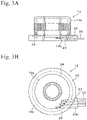
FIG. 3 illustrates a third embodiment of the present invention,FIG. 3(A) is a side view illustrating a mold body, andFIG. 3(B) is a plan view of the mold body. -
FIG. 4 illustrates a fourth embodiment of the present invention,FIG. 4(A) is a side view illustrating a mold body, andFIG. 4(B) is a plan view of the mold body. -
FIG. 5 illustrates a fifth embodiment of the present invention,FIG. 5(A) is a side view illustrating a mold body, andFIG. 5(B) is a plan view of the mold body. -
FIG. 6 illustrates a sixth embodiment of the present invention,FIG. 6(A) is a side view illustrating a mold body, andFIG. 6(B) is a plan view of the mold body. -
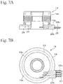
FIG. 7 illustrates a seventh embodiment of the present invention,FIG. 7(A) is a side view illustrating a mold body, andFIG. 7(B) is a plan view of the mold body. -
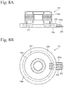
FIG. 8 illustrates an eighth embodiment of the present invention,FIG. 8(A) is a side view illustrating a mold body, andFIG. 8(B) is a plan view of the mold body. -
FIG. 9 illustrates a ninth embodiment of the present invention,FIG. 9(A) is a side view illustrating a mold body, andFIG. 9(B) is a plan view of the mold body. -
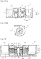
FIG. 10(A) is a cross-sectional view illustrating a fan motor (blower fan) of a modified example of the embodiments of the present invention, andFIG. 10(B) is a plan view of the fan mortar. - FIG. 11(A) is a cross-sectional view illustrating a fan motor (AC axial fan) of another modified example of the embodiments of the present invention.
-
FIG. 1(A) is an axial cross-sectional view illustrating afan motor 10 of an embodiment of the present invention applied to an axial fan, andFIG. 1(B) is an enlarged view of a portion indicated by an arrow B inFIG. 1(A) . As illustrated inFIG. 1(A) , thefan motor 10 of the embodiment includes acasing 11 made of a synthetic resin, astator 20, and arotor 30. - The
casing 11 includes abase portion 14 at the center of a base end portion and a cylindrical bearinghousing 15 fixed to the center of thebase portion 14. The bearinghousing 15 is made of a metal such as brass, for example, and is insert molded into thecasing 11. A pair ofball bearings bearing housing 15 so as to be separated from each other by means of press-fitting or the like. InFIG. 1(A) , areference symbol 16a denotes a coil spring for applying preload to theball bearings - The
stator 20 is disposed at the outer circumferential side of the bearinghousing 15 and includes astator core 21 including a plurality of protruding poles extending outward in the radial direction, abobbin 22 mounted at thestator core 21, and acoil 23 wound around thebobbin 22. Acircuit board 24 is fixed at the lower portion of thebobbin 22 around the base portion of thebearing housing 15. A drive circuit for driving thefan motor 10 is formed andelectronic components circuit board 24. - A
lead wire 25 for energizing the drive circuit is connected to thecircuit board 24. Anend portion 25a of thelead wire 25 is soldered to thecircuit board 24 after a cover made of a resin such as polyvinyl chloride or polyethylene is peeled off. In the drawing, thereference symbol 24a is a connector pin connecting thecircuit board 24 and thecoil 23 with each other, in a state of being inserted into thecircuit board 24 and thebobbin 22. As a result, thestator 20, thecircuit board 24, and thelead wire 25 are integrally joined to form a stator assembly C. - The
rotor 30 includes ashaft 31 made of a metal fixed to theball bearings hub 32 having a cup shape with theshaft 31 being insert molded. A plurality ofblades 33 are integrally formed at an outer circumference of a cylindrical portion of thehub 32, and ayoke 34 is fixed to an inner circumference of the cylindrical portion of thehub 32. Amagnet 35 is fixed to an inner circumference of theyoke 34, and themagnet 35 is arranged to be opposed to an outer circumference of thestator 20. - In the
fan motor 10 having the configuration described above, an opening portion at an upper end side of theblades 33 forms anair suction port 33a, and an opening portion at a lower end side forms adischarge port 33b. Further, in thefan motor 10, a portion of thelead wire 25 up to the vicinity of thecircuit board 24 of the stator assembly C including thestator 20, thecircuit board 24, and thelead wire 25 is integrally molded with afirst mold resin 28 and asecond mold resin 29 before being assembled to thecasing 11. Note that, in the following description, a portion of the stator assembly C molded with thefirst mold resin 28 is referred to as amold body 19. Themold body 19 formed in this manner is a cylindrical body including acylindrical portion 19a covering thestator 20 and aflange portion 19b covering thecircuit board 24. -
FIG. 1(B) is a diagram illustrating details of the lead-out portion of thelead wire 25 led out from thefirst mold resin 28. As illustrated inFIG. 1(B) , theconcave portion 28a is formed at a part of theflange portion 19b of themold body 19 where thelead wire 25 is led out, and theconcave portion 28a is filled with thesecond mold resin 29. Note that the shape of theconcave portion 28a is not particularlylimited, and may be, for example, a cutout portion with an arc-shaped portion missing in a plan view. - The
first mold resin 28 is, for example, an epoxy resin of a thermosetting resin, and thesecond mold resin 29 is, for example, a urethane resin of a thermosetting resin. Thesecond mold resin 29 has the hardness lower than the hardness of thefirst mold resin 28. For example, the hardness of thefirst mold resin 28 at 23°C is D70 or more, and the hardness of thesecond mold resin 29 at 23°C is A90 or less. Preferably, the hardness of thesecond mold resin 29 at 23°C is from A30 to A80. In a case where the hardness of the second mold resin is within this range, thelead wire 25 can be more appropriately protected during work until the stator assembly C with the mold body being formed is attached to thecasing 11. Further, more preferably, the hardness of thefirst mold resin 28 is from D80 to D95, the glass transition point is 125°C or higher, and the linear expansion coefficient at or below the glass transition point is desirably 4 × 10⁻⁵/°C or less. In a case where the characteristics of thefirst mold resin 28 such as the hardness, the glass transition point, and the linear expansion coefficient at or below the glass transition point are within these ranges, the difference between above characteristics of thefirst mold resing 28 and above characteristics of each component constituting the stator assembly C is decreased. As a result, an occurrence of internal stress caused by a change in temperature can be suppressed, the damage to each component constituting the stator assembly C caused by thermal shock can be prevented, and water resistance and oil resistance can be ensured for a longer period of time. Note that the hardness here is measured in accordance with JIS K 7215 (durometer: type A and D), and the glass transition point and the thermal expansion coefficient are measured in accordance with JIS K 7121. - The lead-out portion of the
lead wire 25 as described above is configured as follows. First, in a state where an upper mold of a mold is open, a part to be the lead-out portion of thelead wire 25 of a lower mold is filled with a portion of thesecond mold resin 29 having fluidity, and in this state, the stator assembly C is placed at the lower mold. Next, the part to be the lead-out portion of thelead wire 25 is filled with a remaining portion of thesecond mold resin 29, and the upper mold and the lower mold are closed. Next, the upper mold and the lower mold are heated, and thesecond mold resin 29 is cured. - Next, a remaining space of the mold is filled (injected) with the
first mold resin 28 having fluidity, the mold is heated again, and thefirst mold resin 28 is cured. When thefirst mold resin 28 is cured, the upper mold is opened, and the stator assembly C with themold body 19 being formed is taken out. Then, the stator assembly C is attached to thecasing 11, and theshaft 31 of therotor 30 is fixed to theball bearings fan motor 10 is configured. - In the
fan motor 10 having the configuration described above, thesecond mold resin 29 functions as the grommet member, and of course, the lead-out portion of thelead wire 25 led out from thefirst mold resin 28 can be protected to suppress the damage. In addition, components such as the grommet members are not required. Therefore, the workability is good, because thelead wire 25 need not be inserted into the grommet members. - In particular, in the first embodiment described above, since the
second mold resin 29 does not protrude from a circular contour of themold body 19, an advantage is the same appearance as the appearance of the related art. Further, since thesecond mold resin 29 having a curing start temperature lower than a curing start temperature of thefirst mold resin 28 is used, the first and the second mold resins 28 and 29 can be separately formed, by filling the mold with thesecond mold resin 29 and curing thesecond mold resin 29 and then continuously filling the mold with thefirst mold resin 28 and curing thefirst mold resin 28 without cooling the mold. Alternatively, the first and the second mold resins 28 and 29 can be separately formed, by filling the mold with thesecond mold resin 29 and raising the temperature up to the curing start temperature or higher of the first mold resin 18 to perform curing and then filling the mold with thefirst mold resin 28 to perform curing. The difference between the curing start temperature of thefirst mold resin 28 and the curing start temperature of thesecond mold resin 29 is not particularly limited, but is preferably 10°C or higher. Since the difference between the curing start temperatures is 10°C or higher, a series of steps of curing thefirst mold resin 28 after curing thesecond mold resin 29 can smoothly proceed, and the workability is improved. Note that "curing start temperature" here refers to a temperature of beginning of occurrence of a raising peak indicating curing in a graph showing the relationship between the temperature and the calorific value obtained by differential scanning calorimetry (DSC). -
FIG. 2(A) is a diagram illustrating a modified example of the first embodiment, and illustrates an example of thelead wire 25 being biased in a direction away from thecircuit board 24.FIGS. 2(B) and 2(C) are diagrams illustrating a second embodiment of the present invention, and thesecond mold resin 29 inFIG. 2(A) has a configuration equivalent to the configuration of the above-described embodiment. However, inFIGS. 2(B) and 2(C) , acutout portion 29a is provided at an upper portion of thesecond mold resin 29. In such a second embodiment, the amount of thesecond mold resin 29 used can be reduced. - The above-described first and second embodiments are examples of the
concave portion 28a being provided at the outer circumferential part of theflange portion 19b of themold body 19, and theconcave portion 28a being filled with thesecond mold resin 29. In contrast, in the third embodiment illustrated inFIG. 3 , theconcave portion 28a is not provided at the outer circumferential part of theflange portion 19b, and a protrudingportion 29b made of thesecond mold resin 29 protruding from the outer circumferential part of theflange portion 19b is formed at a part provided with thelead wire 25 led out from thefirst mold resin 28. In the third embodiment, thelead wire 25 can be appropriately protected by appropriately setting the protruding length of the protrudingportion 29b. Further, a direction thelead wire 25 being led out is not particularly limited, but in the third embodiment, thelead wire 25 is led out in a direction not passing through the center of themold body 19. As a result, the protrudingportion 29b has a substantially trapezoidal shape in a plan view, and the amount of protrusion of themold body 19 outward in the radial direction is suppressed. -
FIG. 4 is a diagram illustrating a fourth embodiment of the present invention. In the fourth embodiment, in themold body 19 illustrated inFIG. 2(A) , an outer circumferential surface of thelead wire 25 protruding from thesecond mold resin 29 filling theconcave portion 28a is covered with acover portion 29c made of thesecond mold resin 29 in a predetermined range from thesecond mold resin 29 filling theconcave portion 28a. In such a fourth embodiment, since thelead wire 25 is more appropriately protected by thesecond mold resin 29 entering into themold body 19, and thecover portion 29c, the damage to thelead wire 25 can be further suppressed. Note that in a case where there are a plurality oflead wires 25, thecover portion 29c covers an outer circumferential surface of each of the plurality oflead wires 25, butadjacent cover portions 29c may be partially joined or separated from each other. In the fourth embodiment, thecover portions 29c covering the plurality oflead wires 25 are formed separated from each other. -
FIG. 5 is a diagram illustrating a fifth embodiment of the present invention. In the fifth embodiment, thelead wire 25 protruding from theflange portion 19b is covered with thecover portion 29c made of thesecond mold resin 29. In such a fifth embodiment as well, since thelead wire 25 is protected by thecover portion 29c, the damage to thelead wire 25 can be suppressed. -
FIG. 6 is a diagram illustrating a sixth embodiment of the present invention. In the sixth embodiment, theconcave portion 28a is formed at a part of theflange portion 19b where thelead wire 25 is led out, and theconcave portion 28a is filled with thesecond mold resin 29. Thesecond mold resin 29 is provided so as to protrude from the outer circumferential part of theflange portion 19b, and a protrudingportion 29b is formed. Further, acover portion 29c is provided at thelead wire 25 led out from the protrudingportion 29b. In such a sixth embodiment, since thelead wire 25 is protected by thesecond mold resin 29 inside theconcave portion 28a or the cutout portion, and thesecond mold resin 29 of the protrudingportion 29b and thecover portion 29c, the damage to thelead wire 25 can be further effectively suppressed. -
FIG. 7 is a diagram illustrating a seventh embodiment of the present invention. In the seventh embodiment, a protrudingportion 28b made of thefirst mold resin 28 protruding from the outer circumferential part of theflange portion 19b is formed at a part of theflange portion 19b where thelead wire 25 is led out. Further, thecover portion 29c made of thesecond mold resin 29 is provided at thelead wire 25 led out from the protrudingportion 28b. In such a seventh embodiment as well, since thelead wire 25 is protected by thecover portion 29c, the damage to thelead wire 25 can be suppressed. -
FIG. 8 is a diagram illustrating an eighth embodiment of the present invention. In the eighth embodiment, thelead wire 25 is led out in a direction passing through the center of themold body 19. Theconcave portion 28a is not provided at the outer circumferential part of theflange portion 19b, and a protrudingportion 29b made of thesecond mold resin 29 protruding from the outer circumferential part of theflange portion 19b is formed at a part of thefirst mold resin 28 where thelead wire 25 is led out. The eighth embodiment can also be regarded as a modified example of the fifth embodiment illustrated inFIG. 5 . In the eight embodiment as well, thelead wire 25 can be appropriately protected by appropriately setting the protruding length of the protrudingportion 29b. Further, the amount of thesecond mold resin 29 used can be reduced by appropriately setting the height of the protrudingportion 29b. -
FIG. 9 is a diagram illustrating a ninth embodiment of the present invention. In the ninth embodiment, a protrudingportion 28b made of thefirst mold resin 28 protruding from the outer circumferential part of theflange portion 19b is formed at a part of theflange portion 19b where thelead wire 25 is led out. Further, the protrudingportion 29b made of thesecond mold resin 29 is formed at a tip end portion of the protrudingportion 28b. Then, thecover portion 29c is provided at thelead wire 25 led out from the protrudingportion 29b. In such a ninth embodiment, since thecircuit board 24 can be more reliably covered with thefirst mold resin 28 by providing the protrudingportion 28b, water resistance and oil resistance can be more appropriately ensured and thelead wire 25 is protected by the protrudingportion 29b and thecover portion 29c, so that the damage to thelead wire 25 can be effectively suppressed. - In the embodiment described above, the first and second mold resins 28 and 29 are made of the thermosetting resins, but may also be made of thermoplastic resins. In this case, in a state where the upper mold of the mold is open, the part to be the lead-out portion of the
lead wire 25 of the lower mold is filled with the portion of moltensecond mold resin 29, and in this state, the stator assembly C is placed at the lower mold. Next, the part to be the lead-out portion of thelead wire 25 is filled with a remaining portion of thesecond mold resin 29, and the upper mold and the lower mold are closed. Since the upper mold and the lower mold are at room temperature, thesecond mold resin 29 is cooled to start curing. Next, a remaining space of the mold is filled (injected) with thefirst mold resin 28, and is cooled to perform curing. - The present invention is not limited to the
fan motor 10 for the axial fan such as the above-described embodiments, but can be applied to various fan motors. For example, the present invention can be applied to afan motor 40 for a blower fan (sirocco fan) as illustrated inFIG. 10 . Thefan motor 40 includes astator 20 and arotor 30 similar to the stator and the rotor of the above-described first embodiments. Further, acasing 41 includes ablade 43, and an opening portion at the upper end side of theblade 43 forms anair suction port 43a, and adischarge port 43b is provided at a side portion of thecasing 41. - In such a
fan motor 40 as well, thestator 20, thecircuit board 24, and thelead wire 25 form an integrally joined stator assembly C, and the stator assembly C is molded to form amold body 49. The lead-outportion 49a from themold body 49 of thelead wire 25 has a configuration equivalent to the configuration of the above-described embodiments. In such afan motor 40 as well, an effect equivalent to the effect of the above-described embodiments can be obtained. - The present invention is not limited to an outer rotor type fan motor as described in the above embodiment, but can also be applied to an inner rotor type fan motor.
FIG. 11 illustrates afan motor 50 applied to such an AC axial fan. Thefan motor 50 includes acasing 51, arotor 60, and astator 70. - A
shaft 52 is fixed to the center of thecasing 51, and therotor 60 is rotatably supported at theshaft 52 by a bearinghousing 55 and a pair ofball bearings rotor 60 includes ahub 62 and amagnet 65 fixed at an outer circumferential part of the bearinghousing 55, and ablade 63 is formed at an outer circumferential part of thehub 62. - The
stator 70 attached to thecasing 51 is disposed at an outer circumferential side of themagnet 65. Thestator 70 includes astator core 71 including a plurality of protruding poles extending radially toward the inner circumferential side, abobbin 72 mounted at thestator core 71, and acoil 73 wound around thebobbin 72. Alead wire 75 is connected to thecoil 73. - In the
fan motor 50 having the configuration described above, an opening portion at the upper end side of theblades 63 forms anair suction port 63a, and an opening portion at the lower end side forms adischarge port 63b. In such afan motor 50 as well, thestator 70 and thelead wire 75 form an integrally joined stator assembly C, and the stator assembly C is molded to form amold body 59. The lead-outportion 59a of thelead wire 75 led out from themold body 59 has a configuration equivalent to the configuration of the above-described embodiments, and the same effect as the above-described embodiments can be obtained even in such afan motor 50. - The present invention can be used in the technical field of a fan motor such as an axial fan and a blower fan.
-
- 10 Fan motor
- 11 Casing
- 14 Base portion
- 15 Bearing housing
- 16 Ball bearing
- 17 Ball bearing
- 16a Coil spring
- 19 Mold body
- 19a Cylindrical portion
- 19b Flange portion
- 20 Stator
- 21 Stator core
- 22 Bobbin
- 23 Coil
- 24 Circuit board
- 24a Connector pin
- 25 Lead wire
- 26 Electronic component
- 27 Electronic component
- 28 First mold resin
- 28a Concave portion
- 28b Protruding portion
- 29 Second mold resin
- 29a Cutout portion
- 29b Protruding portion
- 29c Cover portion
- 30 Rotor
- 31 Shaft
- 32 Hub
- 33 Blade
- 33a Suction port
- 33b Discharge port
- 34 Yoke
- 35 Magnet
- 40 Fan motor
- 41 Casing
- 43 Blade
- 43a Suction port
- 43b Discharge port
- 49 Mold body
- 50 Fan motor
- 51 Casing
- 52 Shaft
- 55 Bearing housing
- 56 Ball bearing
- 57 Ball bearing
- 59 Mold body
- 59a Lead-out portion
- 60 Rotor
- 62 Hub
- 63 Blade
- 63a Suction port
- 63b Discharge port
- 65 Magnet
- 70 Stator
- 71 Stator core
- 72 Bobbin
- 73 Coil
- 75 Lead wire
- C Stator assembly
Claims (8)
- A motor comprising:a stator;a circuit board configured to supply a current to the stator;a rotor rotating by the current supplied to the stator;a lead wire connecting an external power supply to the circuit board;a first mold resin covering at least a portion of the stator, at least a portion of the circuit board, and a portion of the lead wire; anda second mold resin covering a predetermined range from the first mold resin of the lead wire led out from the first mold resin,wherein the second mold resin has hardness lower than hardness of the first mold resin.
- The motor according to claim 1,wherein a concave portion or a cutout portion is provided at a portion of an outer circumferential part of the first mold resin where the lead wire is led out, anda second mold resin is provided at the concave portion or the cutout portion.
- The motor according to claim 1,
wherein the second mold resin forms a protruding portion protruding from an outer circumferential portion of the first mold resin. - The motor according to claim 1,wherein a concave portion or a cutout portion is provided at a portion of an outer circumferential part of the first mold resin where the lead wire is led out, andthe second mold resin is provided at the concave portion or the cutout portion, andthe second mold resin forms a protruding portion protruding from the outer circumferential part of the first mold resin.
- The motor according to claim 1,wherein a protruding portion is provided at a portion of an outer circumferential part of the first mold resin where the lead wire is led out, andthe second mold resin covers the lead wire led out from the protruding portion.
- The motor according to any one of claims 1 to 5,wherein a plurality of the lead wires are formed being led out from the first mold resin or the second mold resin, anda cover portion covering an outer circumference of each lead wire with the second mold resin in a predetermined range from the first mold resin or the second mold resin is provided.
- The motor according to any one of claims 1 to 6,wherein the first mold resin and the second mold resin are thermosetting resins, anda curing start temperature of the second mold resin is lower than a curing start temperature of the first mold resin.
- The motor according to any one of claims 1 to 7,wherein the hardness at 23°C of the first mold resin is D70 or more, andthe hardness at 23°C of the second mold resin is A90 or less.
Applications Claiming Priority (2)
| Application Number | Priority Date | Filing Date | Title |
|---|---|---|---|
| JP2019164706A JP7348781B2 (en) | 2019-09-10 | 2019-09-10 | fan motor |
| PCT/JP2020/030948 WO2021049252A1 (en) | 2019-09-10 | 2020-08-17 | Fan motor |
Publications (3)
| Publication Number | Publication Date |
|---|---|
| EP4030592A1 true EP4030592A1 (en) | 2022-07-20 |
| EP4030592A4 EP4030592A4 (en) | 2023-09-27 |
| EP4030592B1 EP4030592B1 (en) | 2025-10-01 |
Family
ID=74864392
Family Applications (1)
| Application Number | Title | Priority Date | Filing Date |
|---|---|---|---|
| EP20862347.0A Active EP4030592B1 (en) | 2019-09-10 | 2020-08-17 | Fan motor |
Country Status (5)
| Country | Link |
|---|---|
| US (2) | US12294276B2 (en) |
| EP (1) | EP4030592B1 (en) |
| JP (1) | JP7348781B2 (en) |
| CN (1) | CN114365397A (en) |
| WO (1) | WO2021049252A1 (en) |
Families Citing this family (1)
| Publication number | Priority date | Publication date | Assignee | Title |
|---|---|---|---|---|
| US20250240913A1 (en) * | 2024-01-18 | 2025-07-24 | Apple Inc. | Fan base for providing power and signals between components |
Family Cites Families (23)
| Publication number | Priority date | Publication date | Assignee | Title |
|---|---|---|---|---|
| US3313983A (en) * | 1965-08-27 | 1967-04-11 | Central Transformer Corp | Transformers |
| TW263629B (en) | 1992-05-27 | 1995-11-21 | Nihon Densan Kk | |
| JPH0851741A (en) * | 1994-08-05 | 1996-02-20 | Sanwa Chem Kk | Mold motor |
| JPH09121497A (en) | 1995-10-25 | 1997-05-06 | Matsushita Electric Ind Co Ltd | Electric motor stator |
| JP3550028B2 (en) | 1998-10-09 | 2004-08-04 | 山洋電気株式会社 | Brushless fan motor and method of manufacturing the same |
| JP3730461B2 (en) * | 1999-10-28 | 2006-01-05 | 山洋電気株式会社 | Waterproof brushless fan motor |
| JP3401640B2 (en) * | 2000-02-29 | 2003-04-28 | ミネベア株式会社 | Blower and manufacturing method thereof |
| KR100682120B1 (en) | 2001-04-18 | 2007-02-15 | 삼성광주전자 주식회사 | Stator of mold motor and its manufacturing method |
| JP4555912B2 (en) | 2001-07-10 | 2010-10-06 | 多摩川精機株式会社 | Resolver stator structure |
| JP2005341640A (en) | 2004-05-24 | 2005-12-08 | Koyo Seiko Co Ltd | Stator of motor |
| US7090284B2 (en) * | 2004-07-27 | 2006-08-15 | Lear Corporation | Trim assembly having an integrated grommet and method of making the same |
| JP4747754B2 (en) * | 2005-09-16 | 2011-08-17 | 日本電産株式会社 | motor |
| US8004125B2 (en) * | 2007-04-19 | 2011-08-23 | Mitsubishi Electric Corporation | Motor, pump, and method of manufacturing the motor |
| JP2009112067A (en) * | 2007-10-26 | 2009-05-21 | Nidec Shibaura Corp | Mold motor |
| JP5486890B2 (en) | 2009-09-30 | 2014-05-07 | ミネベア株式会社 | Fan motor |
| JP5646270B2 (en) * | 2010-10-06 | 2014-12-24 | 株式会社東芝 | Protective sleeve, rotating electric machine with protective sleeve, manufacturing method of protective sleeve, and manufacturing method of rotating electric machine with protective sleeve |
| JP5942585B2 (en) | 2012-05-16 | 2016-06-29 | コベルコ建機株式会社 | Electric motor and manufacturing method thereof |
| US9657879B1 (en) * | 2013-03-15 | 2017-05-23 | Mercury Plastics, Inc. | Tube connection assembly |
| JP6096894B2 (en) * | 2013-05-31 | 2017-03-15 | 株式会社Top | Rotating machine |
| US9613831B2 (en) * | 2015-03-25 | 2017-04-04 | Qorvo Us, Inc. | Encapsulated dies with enhanced thermal performance |
| JP2018148607A (en) | 2017-03-01 | 2018-09-20 | 日本電産株式会社 | Base unit, motor, and blower |
| JP2018148606A (en) * | 2017-03-01 | 2018-09-20 | 日本電産株式会社 | Base unit, motor, and blower |
| JP2018178898A (en) | 2017-04-17 | 2018-11-15 | 日本電産株式会社 | Blowing device, blowing unit, and method of manufacturing blowing device |
-
2019
- 2019-09-10 JP JP2019164706A patent/JP7348781B2/en active Active
-
2020
- 2020-08-17 WO PCT/JP2020/030948 patent/WO2021049252A1/en not_active Ceased
- 2020-08-17 US US17/753,494 patent/US12294276B2/en active Active
- 2020-08-17 CN CN202080062672.9A patent/CN114365397A/en active Pending
- 2020-08-17 EP EP20862347.0A patent/EP4030592B1/en active Active
-
2024
- 2024-12-30 US US19/004,961 patent/US20250141299A1/en active Pending
Also Published As
| Publication number | Publication date |
|---|---|
| US20220329129A1 (en) | 2022-10-13 |
| US20250141299A1 (en) | 2025-05-01 |
| EP4030592B1 (en) | 2025-10-01 |
| JP2021044917A (en) | 2021-03-18 |
| JP7348781B2 (en) | 2023-09-21 |
| WO2021049252A1 (en) | 2021-03-18 |
| US12294276B2 (en) | 2025-05-06 |
| EP4030592A4 (en) | 2023-09-27 |
| CN114365397A (en) | 2022-04-15 |
Similar Documents
| Publication | Publication Date | Title |
|---|---|---|
| US6002185A (en) | Molded motor | |
| US9634533B2 (en) | Motor with a stator having four separate corner bobbins/insulators and molded resin insulation around tooth completely enclosing the coil and manufacturing method thereof | |
| CN106468283B (en) | Centrifugal fan | |
| JP7102661B2 (en) | motor | |
| EP2793370B1 (en) | Fan motor | |
| KR101074935B1 (en) | Fam motor assembly for blowing cooling air | |
| US10530213B2 (en) | Stator unit, motor, and fan motor | |
| US20190036388A1 (en) | Stator, motor, air blower, and method of manufacturing stator | |
| US20250141299A1 (en) | Fan motor | |
| KR20130054136A (en) | Mold motor | |
| JP2008069672A (en) | Fan | |
| US20150176587A1 (en) | Fan | |
| US20180205281A1 (en) | Motor | |
| CN208153387U (en) | Aerofoil fan | |
| US20150162791A1 (en) | Rotor and motor including the same | |
| US20170353090A1 (en) | Stator unit, motor, and blower | |
| JP2017184525A (en) | Stator unit, motor and parallel fan | |
| US20010006598A1 (en) | Blower | |
| US11677300B2 (en) | Motor and blower | |
| US8796900B2 (en) | Electric motor | |
| JP5009219B2 (en) | Electric motor | |
| AU2019459440B2 (en) | Electric motor, fan, air conditioning device, and method for manufacturing electric motor | |
| JPWO2023053199A5 (en) | ||
| JP6946065B2 (en) | Brushed motor | |
| KR20150083681A (en) | Motor rotor and method for manufacturing the same |
Legal Events
| Date | Code | Title | Description |
|---|---|---|---|
| STAA | Information on the status of an ep patent application or granted ep patent |
Free format text: STATUS: THE INTERNATIONAL PUBLICATION HAS BEEN MADE |
|
| PUAI | Public reference made under article 153(3) epc to a published international application that has entered the european phase |
Free format text: ORIGINAL CODE: 0009012 |
|
| STAA | Information on the status of an ep patent application or granted ep patent |
Free format text: STATUS: REQUEST FOR EXAMINATION WAS MADE |
|
| 17P | Request for examination filed |
Effective date: 20220304 |
|
| AK | Designated contracting states |
Kind code of ref document: A1 Designated state(s): AL AT BE BG CH CY CZ DE DK EE ES FI FR GB GR HR HU IE IS IT LI LT LU LV MC MK MT NL NO PL PT RO RS SE SI SK SM TR |
|
| DAV | Request for validation of the european patent (deleted) | ||
| DAX | Request for extension of the european patent (deleted) | ||
| A4 | Supplementary search report drawn up and despatched |
Effective date: 20230830 |
|
| RIC1 | Information provided on ipc code assigned before grant |
Ipc: H02K 3/52 20060101ALI20230824BHEP Ipc: H02K 7/14 20060101ALI20230824BHEP Ipc: H02K 5/22 20060101ALI20230824BHEP Ipc: H02K 5/08 20060101AFI20230824BHEP |
|
| STAA | Information on the status of an ep patent application or granted ep patent |
Free format text: STATUS: EXAMINATION IS IN PROGRESS |
|
| 17Q | First examination report despatched |
Effective date: 20240411 |
|
| P01 | Opt-out of the competence of the unified patent court (upc) registered |
Free format text: CASE NUMBER: APP_52610/2024 Effective date: 20240919 |
|
| GRAP | Despatch of communication of intention to grant a patent |
Free format text: ORIGINAL CODE: EPIDOSNIGR1 |
|
| STAA | Information on the status of an ep patent application or granted ep patent |
Free format text: STATUS: GRANT OF PATENT IS INTENDED |
|
| INTG | Intention to grant announced |
Effective date: 20250530 |
|
| GRAS | Grant fee paid |
Free format text: ORIGINAL CODE: EPIDOSNIGR3 |
|
| GRAA | (expected) grant |
Free format text: ORIGINAL CODE: 0009210 |
|
| STAA | Information on the status of an ep patent application or granted ep patent |
Free format text: STATUS: THE PATENT HAS BEEN GRANTED |
|
| AK | Designated contracting states |
Kind code of ref document: B1 Designated state(s): AL AT BE BG CH CY CZ DE DK EE ES FI FR GB GR HR HU IE IS IT LI LT LU LV MC MK MT NL NO PL PT RO RS SE SI SK SM TR |
|
| REG | Reference to a national code |
Ref country code: GB Ref legal event code: FG4D Ref country code: CH Ref legal event code: F10 Free format text: ST27 STATUS EVENT CODE: U-0-0-F10-F00 (AS PROVIDED BY THE NATIONAL OFFICE) Effective date: 20251001 |
|
| REG | Reference to a national code |
Ref country code: IE Ref legal event code: FG4D |
|
| REG | Reference to a national code |
Ref country code: DE Ref legal event code: R096 Ref document number: 602020059886 Country of ref document: DE |
|
| REG | Reference to a national code |
Ref country code: NL Ref legal event code: MP Effective date: 20251001 |
|
| REG | Reference to a national code |
Ref country code: AT Ref legal event code: MK05 Ref document number: 1843583 Country of ref document: AT Kind code of ref document: T Effective date: 20251001 |
|
| PG25 | Lapsed in a contracting state [announced via postgrant information from national office to epo] |
Ref country code: NL Free format text: LAPSE BECAUSE OF FAILURE TO SUBMIT A TRANSLATION OF THE DESCRIPTION OR TO PAY THE FEE WITHIN THE PRESCRIBED TIME-LIMIT Effective date: 20251001 |
|
| PG25 | Lapsed in a contracting state [announced via postgrant information from national office to epo] |
Ref country code: ES Free format text: LAPSE BECAUSE OF FAILURE TO SUBMIT A TRANSLATION OF THE DESCRIPTION OR TO PAY THE FEE WITHIN THE PRESCRIBED TIME-LIMIT Effective date: 20251001 |
|
| REG | Reference to a national code |
Ref country code: LT Ref legal event code: MG9D |
|
| PG25 | Lapsed in a contracting state [announced via postgrant information from national office to epo] |
Ref country code: NO Free format text: LAPSE BECAUSE OF FAILURE TO SUBMIT A TRANSLATION OF THE DESCRIPTION OR TO PAY THE FEE WITHIN THE PRESCRIBED TIME-LIMIT Effective date: 20260101 |
|
| PG25 | Lapsed in a contracting state [announced via postgrant information from national office to epo] |
Ref country code: HR Free format text: LAPSE BECAUSE OF FAILURE TO SUBMIT A TRANSLATION OF THE DESCRIPTION OR TO PAY THE FEE WITHIN THE PRESCRIBED TIME-LIMIT Effective date: 20251001 Ref country code: FI Free format text: LAPSE BECAUSE OF FAILURE TO SUBMIT A TRANSLATION OF THE DESCRIPTION OR TO PAY THE FEE WITHIN THE PRESCRIBED TIME-LIMIT Effective date: 20251001 Ref country code: AT Free format text: LAPSE BECAUSE OF FAILURE TO SUBMIT A TRANSLATION OF THE DESCRIPTION OR TO PAY THE FEE WITHIN THE PRESCRIBED TIME-LIMIT Effective date: 20251001 |
|
| PG25 | Lapsed in a contracting state [announced via postgrant information from national office to epo] |
Ref country code: RS Free format text: LAPSE BECAUSE OF FAILURE TO SUBMIT A TRANSLATION OF THE DESCRIPTION OR TO PAY THE FEE WITHIN THE PRESCRIBED TIME-LIMIT Effective date: 20260101 |
|
| PG25 | Lapsed in a contracting state [announced via postgrant information from national office to epo] |
Ref country code: IS Free format text: LAPSE BECAUSE OF FAILURE TO SUBMIT A TRANSLATION OF THE DESCRIPTION OR TO PAY THE FEE WITHIN THE PRESCRIBED TIME-LIMIT Effective date: 20260201 |
|
| PG25 | Lapsed in a contracting state [announced via postgrant information from national office to epo] |
Ref country code: PT Free format text: LAPSE BECAUSE OF FAILURE TO SUBMIT A TRANSLATION OF THE DESCRIPTION OR TO PAY THE FEE WITHIN THE PRESCRIBED TIME-LIMIT Effective date: 20260202 Ref country code: CZ Free format text: LAPSE BECAUSE OF FAILURE TO SUBMIT A TRANSLATION OF THE DESCRIPTION OR TO PAY THE FEE WITHIN THE PRESCRIBED TIME-LIMIT Effective date: 20251001 |
|
| PG25 | Lapsed in a contracting state [announced via postgrant information from national office to epo] |
Ref country code: PL Free format text: LAPSE BECAUSE OF FAILURE TO SUBMIT A TRANSLATION OF THE DESCRIPTION OR TO PAY THE FEE WITHIN THE PRESCRIBED TIME-LIMIT Effective date: 20251001 |
|
| PG25 | Lapsed in a contracting state [announced via postgrant information from national office to epo] |
Ref country code: LV Free format text: LAPSE BECAUSE OF FAILURE TO SUBMIT A TRANSLATION OF THE DESCRIPTION OR TO PAY THE FEE WITHIN THE PRESCRIBED TIME-LIMIT Effective date: 20251001 |
|
| PG25 | Lapsed in a contracting state [announced via postgrant information from national office to epo] |
Ref country code: BG Free format text: LAPSE BECAUSE OF FAILURE TO SUBMIT A TRANSLATION OF THE DESCRIPTION OR TO PAY THE FEE WITHIN THE PRESCRIBED TIME-LIMIT Effective date: 20251001 |
|
| PG25 | Lapsed in a contracting state [announced via postgrant information from national office to epo] |
Ref country code: LT Free format text: LAPSE BECAUSE OF FAILURE TO SUBMIT A TRANSLATION OF THE DESCRIPTION OR TO PAY THE FEE WITHIN THE PRESCRIBED TIME-LIMIT Effective date: 20251001 |
|
| PG25 | Lapsed in a contracting state [announced via postgrant information from national office to epo] |
Ref country code: SM Free format text: LAPSE BECAUSE OF FAILURE TO SUBMIT A TRANSLATION OF THE DESCRIPTION OR TO PAY THE FEE WITHIN THE PRESCRIBED TIME-LIMIT Effective date: 20251001 |
|
| PG25 | Lapsed in a contracting state [announced via postgrant information from national office to epo] |
Ref country code: DK Free format text: LAPSE BECAUSE OF FAILURE TO SUBMIT A TRANSLATION OF THE DESCRIPTION OR TO PAY THE FEE WITHIN THE PRESCRIBED TIME-LIMIT Effective date: 20251001 |
|
| PG25 | Lapsed in a contracting state [announced via postgrant information from national office to epo] |
Ref country code: EE Free format text: LAPSE BECAUSE OF FAILURE TO SUBMIT A TRANSLATION OF THE DESCRIPTION OR TO PAY THE FEE WITHIN THE PRESCRIBED TIME-LIMIT Effective date: 20251001 |
|
| PG25 | Lapsed in a contracting state [announced via postgrant information from national office to epo] |
Ref country code: SK Free format text: LAPSE BECAUSE OF FAILURE TO SUBMIT A TRANSLATION OF THE DESCRIPTION OR TO PAY THE FEE WITHIN THE PRESCRIBED TIME-LIMIT Effective date: 20251001 |
|
| PG25 | Lapsed in a contracting state [announced via postgrant information from national office to epo] |
Ref country code: SE Free format text: LAPSE BECAUSE OF FAILURE TO SUBMIT A TRANSLATION OF THE DESCRIPTION OR TO PAY THE FEE WITHIN THE PRESCRIBED TIME-LIMIT Effective date: 20251001 |
|
| PLBE | No opposition filed within time limit |
Free format text: ORIGINAL CODE: 0009261 |
|
| STAA | Information on the status of an ep patent application or granted ep patent |
Free format text: STATUS: NO OPPOSITION FILED WITHIN TIME LIMIT |
|
| REG | Reference to a national code |
Ref country code: CH Ref legal event code: L10 Free format text: ST27 STATUS EVENT CODE: U-0-0-L10-L00 (AS PROVIDED BY THE NATIONAL OFFICE) Effective date: 20260812 |