EP4030567A1 - Electrical connector with plug latching assembly - Google Patents
Electrical connector with plug latching assembly Download PDFInfo
- Publication number
- EP4030567A1 EP4030567A1 EP22160502.5A EP22160502A EP4030567A1 EP 4030567 A1 EP4030567 A1 EP 4030567A1 EP 22160502 A EP22160502 A EP 22160502A EP 4030567 A1 EP4030567 A1 EP 4030567A1
- Authority
- EP
- European Patent Office
- Prior art keywords
- latch
- plug
- compartment
- receptacle
- latches
- Prior art date
- Legal status (The legal status is an assumption and is not a legal conclusion. Google has not performed a legal analysis and makes no representation as to the accuracy of the status listed.)
- Pending
Links
Images









Classifications
-
- H—ELECTRICITY
- H01—ELECTRIC ELEMENTS
- H01R—ELECTRICALLY-CONDUCTIVE CONNECTIONS; STRUCTURAL ASSOCIATIONS OF A PLURALITY OF MUTUALLY-INSULATED ELECTRICAL CONNECTING ELEMENTS; COUPLING DEVICES; CURRENT COLLECTORS
- H01R13/00—Details of coupling devices of the kinds covered by groups H01R12/70 or H01R24/00 - H01R33/00
- H01R13/62—Means for facilitating engagement or disengagement of coupling parts or for holding them in engagement
- H01R13/627—Snap or like fastening
- H01R13/6271—Latching means integral with the housing
-
- H—ELECTRICITY
- H01—ELECTRIC ELEMENTS
- H01R—ELECTRICALLY-CONDUCTIVE CONNECTIONS; STRUCTURAL ASSOCIATIONS OF A PLURALITY OF MUTUALLY-INSULATED ELECTRICAL CONNECTING ELEMENTS; COUPLING DEVICES; CURRENT COLLECTORS
- H01R13/00—Details of coupling devices of the kinds covered by groups H01R12/70 or H01R24/00 - H01R33/00
- H01R13/02—Contact members
- H01R13/193—Means for increasing contact pressure at the end of engagement of coupling part, e.g. zero insertion force or no friction
-
- H—ELECTRICITY
- H01—ELECTRIC ELEMENTS
- H01R—ELECTRICALLY-CONDUCTIVE CONNECTIONS; STRUCTURAL ASSOCIATIONS OF A PLURALITY OF MUTUALLY-INSULATED ELECTRICAL CONNECTING ELEMENTS; COUPLING DEVICES; CURRENT COLLECTORS
- H01R13/00—Details of coupling devices of the kinds covered by groups H01R12/70 or H01R24/00 - H01R33/00
- H01R13/62—Means for facilitating engagement or disengagement of coupling parts or for holding them in engagement
- H01R13/627—Snap or like fastening
- H01R13/6275—Latching arms not integral with the housing
-
- H—ELECTRICITY
- H01—ELECTRIC ELEMENTS
- H01R—ELECTRICALLY-CONDUCTIVE CONNECTIONS; STRUCTURAL ASSOCIATIONS OF A PLURALITY OF MUTUALLY-INSULATED ELECTRICAL CONNECTING ELEMENTS; COUPLING DEVICES; CURRENT COLLECTORS
- H01R13/00—Details of coupling devices of the kinds covered by groups H01R12/70 or H01R24/00 - H01R33/00
- H01R13/02—Contact members
- H01R13/22—Contacts for co-operating by abutting
- H01R13/24—Contacts for co-operating by abutting resilient; resiliently-mounted
- H01R13/2407—Contacts for co-operating by abutting resilient; resiliently-mounted characterized by the resilient means
- H01R13/2421—Contacts for co-operating by abutting resilient; resiliently-mounted characterized by the resilient means using coil springs
-
- H—ELECTRICITY
- H01—ELECTRIC ELEMENTS
- H01R—ELECTRICALLY-CONDUCTIVE CONNECTIONS; STRUCTURAL ASSOCIATIONS OF A PLURALITY OF MUTUALLY-INSULATED ELECTRICAL CONNECTING ELEMENTS; COUPLING DEVICES; CURRENT COLLECTORS
- H01R13/00—Details of coupling devices of the kinds covered by groups H01R12/70 or H01R24/00 - H01R33/00
- H01R13/62—Means for facilitating engagement or disengagement of coupling parts or for holding them in engagement
- H01R13/623—Casing or ring with helicoidal groove
Definitions
- the present disclosure relates to electrical connectors, and in particular to pin-and-sleeve type electrical connectors.
- Standard pin and sleeve devices typically have a male plug with contact pins and a female receptacle with mating sleeve-like contacts sometimes called contact sleeves.
- Some form of plug-to-receptacle latching is usually provided at least to minimize accidental separation of the male plug from the female receptacle.
- the electrical connection is made through the mechanical insertion of the contact pins in the male plug into the contact sleeves in the female receptacle. For safety, the receptacle's contact sleeves may not be energized or accessible until the plug and receptacle are properly coupled.
- the latch assembly includes a housing, plurality of latches, a latch lever and a plurality of latch lever arms extending from the latch lever such that one latch lever arm is operatively coupled to one latch.
- the housing has a latch compartment and a latch lever compartment.
- the plurality of latches are positioned within the latch compartment of the cover and rotatable between a plug capture position and a plug release position.
- the latch lever is pivotably positioned at least partially within the latch lever compartment. In this configuration pivotable movement of the latch lever is translated to rotational movement of the latches between the plug capture position and the plug release position.
- the latch assembly includes a housing, first and second latches, a latch lever, and first and second latch lever arms extending from the latch lever such that the first latch lever arm is operatively coupled to the first latch, and the second latch lever arm is operatively coupled to the second latch.
- the housing has a latch compartment and a latch lever compartment, and the first and second latches are positioned within the latch compartment and rotatable between a plug capture position and a plug release position.
- the latch lever is pivotably positioned at least partially within the latch lever compartment.
- the first latch lever arm extends into the latch compartment and is operatively coupled to the first latch
- the second latch lever arm extends into the latch compartment and is operatively coupled to the second latch.
- pivotable movement of the latch lever can be translated to rotational movement of the first and second latches between the plug capture position and the plug release position.
- the latch assembly of the present disclosure shortens the displacements and force required to release the plug from the receptacle. This is achieved by lessening the deflection requirements for the latches.
- the present disclosure also provides pin-and-sleeve type electrical connectors that have a plug that can be coupled to a receptacle.
- the receptacle of the electrical connectors include the latch assembly described above.
- a male plug 1 for mating with a female receptacle 100 of a pin-and-sleeve type electrical connector is shown.
- the term plug relates to a male half of a pin-and-sleeve electrical connector
- the term "receptacle” relates to a female half of a pin-and-sleeve electrical connector regardless of how the receptacle is mounted, e.g., surface mounted, in-wall mounted or panel mounted, or how the receptacle is connected to a power source, e.g., connected to a power source via a cable.
- the plug may be a female half of the pin-in-sleeve electrical connector
- the receptacle may be a male half of the pin-in-sleeve electrical connector.
- the plug 1 has a cylindrical front safety shroud 1 a surrounding a plurality of line contact pins 1 b and a rotatable locking ring 1 d .
- the shroud 1a may also surround a ground contact pin 1 e.
- the line contact pins 1b within the plug 1 are adapted to mate with contact sleeves 8 within sleeve carrier 10 in the receptacle 100.
- the ground contact pin 1e is adapted to mate with a ground sleeve assembly 17.
- the shroud 1 a of the plug 1 has an integrally formed, radially projecting indexing rib 1 c at its front end.
- the indexing rib 1 c which may be a tab, interacts with a latching assembly 200 of the receptacle 100 as will be described in more detail below.
- the rotatable locking ring Id has two lugs (not shown) adapted to mate with two standard ramped locking flanges 2 a at the front end of an upper housing 2 of the receptacle 100.
- a standard butted rubber gasket (not shown) seals the interface between the plug 1 and the receptacle 100 when they are fully mated.
- the receptacle 100 has an upper housing 2 and a lower housing 36.
- the lower housing 36 is secured to the upper housing 2 using, for example, screws 38 with an interposed sealing gasket 35 between the two housings.
- the lower housing 36 can be configured for connection to a cable.
- the upper housing 2 can be mated instead to various adapters (not shown) using screws to enable mounting of the receptacle 100 on a surface, in a wall, in a panel, etc.
- a sleeve carrier assembly according to the present disclosure is positioned within the receptacle 100 and includes a sleeve carrier housing 3, a sleeve carrier 10 with its internal components and a terminal retainer 15 with its internal components as described herein.
- FIG. 3 and 8 an exemplary embodiment of a portion of the sleeve carrier assembly is shown.
- Three line contact sleeves 8 of this exemplary embodiment are fixed in the sleeve carrier 10 by a sleeve carrier cap 6 held in place by screws 5.
- the sleeve carrier 10 is positioned within the sleeve carrier housing 3 and axially movable within the sleeve carrier housing.
- the sleeve carrier housing 3 is fixed in place within the upper housing 2 of the receptacle 100 by abutting the terminal retainer 15 to the sleeve carrier housing and securing the terminal retainer within the upper housing 2 using mounting screws 21.
- Two helical carriage springs 11 are interposed between the sleeve carrier 10 and the terminal retainer 15 and used to bias the sleeve carrier 10 away from the pressure contacts 18.
- the three contact sleeves 8 have inwardly facing electrical contact tips 8 a that are axially movable into and out of engagement with a corresponding electrical contact tip 18 a of an equal number of braided, spring-loaded contact terminals 18.
- the contact terminals 18 may also be referred to herein as "pressure contacts.”
- the contact tips 8 a and 18 a may be silver contact tips.
- the pressure contacts 18 are conventional electrical contacts, examples of which are described in U.S. Patent No. 4,176,905 , which is incorporated herein in its entirety by reference.
- the pressure contacts 18 are supported in a terminal retainer 15 by a terminal retainer cap 19 fastened to the terminal retainer 15 by screws 20.
- the terminal retainer 15 is secured to the upper housing 2 using screws 21, as noted above, to secure the carrier sleeve assembly within the receptacle 100.
- the receptacle 100 may also include a continuous ground configuration that ensures grounding of the primary electrical circuit when inserting and withdrawing the plug 1 relative to the receptacle 100.
- a ground sleeve assembly 17 is fixed in the terminal retainer 15 and extends freely through sleeve carrier 10 where a distal end 17 a of the ground sleeve assembly 17 begins to mate with a ground contact pin 1e of a plug 1 upon initial insertion of the plug into the receptacle 100 and before the line contact sleeves 8 mate with their respective line contact pins 1b.
- the ground sleeve assembly 17 unlike the line contact sleeves 8, is not supported in or moved by sleeve carrier 10 and has no electrical contact tip on its inner end.
- the sleeve carrier 10 moves along the fixed ground sleeve assembly 17 such that the ground connection between the plug 1 and the receptacle 100 does rely on a pressure contact.
- the ground contact pin 1e of the plug 1 is the last contact pin to disengage from the ground sleeve assembly 17 maintaining an electrical path to ground during withdrawal of the plug 1 from the receptacle 100.
- the sleeve carrier 10 is positioned within the sleeve carrier housing 3 and axially movable within the sleeve carrier housing as noted above.
- the sleeve carrier housing 3 has two diametrically opposed windows 40, seen in Fig. 5 , that join respective narrower longitudinal slots 41 extending from the respective window 40 toward the terminal retainer 15.
- the upper end 7 a of two inwardly deflectable resilient retaining clips 7 are anchored in respective recesses 42 in the sleeve carrier 10, as shown in Fig. 7 .
- Each retaining clip 7 has an inclined, ribbed ramp portion 43 and a pair of lateral wings or shoulders 44.
- the retaining clips 7 may include a cover made of a thermoplastic material, such as Polyoxymethylene which may be sold for example under the name Delrin ® .
- a cover made of a thermoplastic material such as Polyoxymethylene which may be sold for example under the name Delrin ® .
- the ramp portions 43 project outward through their respective window 40 in the carrier housing 3 and the shoulders 44 engage the lower edges of their respective window 40, as shown in Fig. 7 .
- the shoulders 44 of the retaining clips 7 prevent downward movement of the sleeve carrier 10 relative to the carrier housing 3 keeping the contact sleeves 8 separated from the pressure contacts 18 (seen for example in Fig. 10 ).
- the ramp portions 43 of the retaining clips 7 project into the path traveled by the plug shroud 1a of the plug 1 when the plug is mated with the receptacle 100.
- the receptacle 100 also includes a modular clocking design that enables variable angular positioning of the terminal retainer 15 within the upper housing 2 so that a variety of terminal contact configurations can be achieved when manufacturing the receptacle 100 without having to stock differently configured terminal retainers.
- the upper housing 2 has a clocking key 50 facing the periphery of terminal retainer 15, which has a plurality of peripheral clocking knockouts 51. The appropriate clocking knockout 51 is broken out during assembly of the receptacle 100 depending on the terminal configuration specified for the unit.
- the terminal retainer 15 and thus the pressure contacts 18 can be adjusted to align with the line contact sleeves 8 and the contact sleeve openings 3 a , 3b and 3 c in the sleeve carrier housing 3, seen in Fig. 5 , and the ground sleeve assembly 17 can be aligned with the ground contact opening 3 d in the sleeve carrier housing.
- the receptacle 100 may also include a status indicator assembly that uses the primary power circuit to power a low-current lighting control circuit.
- the status indicator assembly includes first and second bridge connectors 9 a and 9 b , top and bottom connection clips 4 and 16, top and bottom cylindrical contact rings 13 a and 13 b , contact ring holders 14 and printed circuit board (PCB) assemblies 12.
- the first bridge connector 9 a is connected at one end to a line contact sleeve 8 and at another end to the top connection clip 4.
- the top connection clip 4 is connected to the top contact ring 13 a thus forming an electrically conductive path between the line contact sleeve 8 and the top contact ring 13 a .
- the second bridge connector 9 b is connected at one end to another line contact sleeve 8 and at another end to the bottom connection clip 16.
- the bottom connection clip 16 is connected to the bottom contact ring 13 b thus forming an electrically conductive path between the line contact sleeve 8 and the bottom contact ring 13 b .
- the contact rings 13 a and 13 b can be cylindrical rings that may be of unitary construction or that may have two halves. Each contact ring 13 a and 13 b is held in place on the terminal retainer 15 using contact ring holder 14.
- Each PCB assembly 12 may be a plug-in type PCB that includes an integral LED or other lighting element and a lighting control circuit to illuminate the LED.
- Each PCB assembly 12 also includes an LED lens 24 and an interposed lens gasket 23, seen in Figs. 3 and 9 .
- closure of the primary electrical circuit occurs upon the full engagement of the plug 1 to the receptacle 100. Closure of the primary electrical circuit also completes the lighting control circuit energizing the LEDs.
- the illuminated LEDs are visible through observation windows 52 on opposite sides of upper housing 2, seen in for example Figs. 1 and 3 , providing a visual indication that power is being supplied between the plug 1 and the receptacle 100.
- the receptacle 100 also includes a pushbutton assembly 150 having a pushbutton 25 that is sealed to the upper housing 2 by a button seal cup 27 and a button lip seal 28.
- the pushbutton 25 has a pushbutton pin 25 a that passes through a spring 26, the button seal cup 27, the button lip seal 28 and extends through the upper housing 2 into a latch assembly pocket 2 b in the upper housing, as seen in Fig. 2 .
- the spring 26 normally biases the pushbutton 25 away from the upper housing 2.
- the pushbutton assembly 150 is surrounded on three sides by a U-shaped rim 48 integrally formed into the upper housing 2. The rim 48 protects the pushbutton assembly 150 from damage while providing sufficient space in the recess around the pushbutton 25 to keep dust and debris from accumulating in that region.
- the latch assembly pocket 2b in the upper housing 2 supports a latching assembly 200 that interacts with the indexing rib 1 c of the plug 1 and the pushbutton assembly 150 during coupling and decoupling of the plug 1 relative to the receptacle 100.
- the latching assembly 200 selectively permits or inhibits decoupling movement of the plug 1 relative to the receptacle 100, and may provide a positive and audible engagement of the plug 1 as it mates with the receptacle 100.
- the latch assembly 200 includes a latch assembly housing 202, a pair of rotating (or pivoting) latches 210 and 212, and latch lever 214.
- the latch assembly housing 202 is supported within the pocket 2b of the upper housing 2, as noted above and as shown in Fig. 4 .
- the latch assembly housing 202 has a latch compartment 222 configured to receive the latches 210 and 212 and corresponding springs 216 and 218.
- the latch assembly housing 202 also has a latch lever compartment 224 configured to receive the latch lever 214.
- the latch assembly housing 202 also has an indexing rib portal 220 that provides an entry to the latch compartment 222 and the latch lever compartment 224.
- the latch 210 is secured within the latch compartment 222 using latch pivot pin 228 so that the latch 210 can rotate between the plug capture position, seen in Figs. 14-16 , and the plug release position, seen in Figs. 17-19 .
- the latch 212 is secured within the latch compartment 222 using latch pivot pin 230 so that the latch 212 can rotate between the plug capture position and the plug release position.
- the latches 210 and 212 are normally biased inwardly by the respective springs 216 and 218 toward the plug-capture position, i.e., in a direction so that the latches 210 and 212 extend within the path of an indexing rib portal 220, as seen in Figs. 14-16 .
- the latch lever 214 is secured within the latch lever compartment 224 using latch lever pin 226 so that the latch lever 214 is pivotable within the latch lever compartment 224 relative to the latch assembly housing 202.
- the latch lever 214 includes latch lever arms 232 and 234, and a latch lever push bar 236.
- Latch lever arm 232 passes through the latch lever compartment 224 into the latch compartment 222 and fits within aperture 210 a in latch 210.
- the latch lever arm 234 passes through the latch lever compartment 224 into the latch compartment 222 and fits within aperture 212 a in latch 212.
- the latch assembly 200 of the present disclosure reduces the force to be applied to the pushbutton 25 and the pushbutton stroke deflection in order to decouple the plug 1 from the receptacle 100.
- the force needed to decouple the plug 1 from the receptacle 100 can, for example, range from about 10 lbs. to about 25 lbs.
- an angle of rotation of each latch 210 and 212 can be, for example, less than 25 degrees of rotation, and preferably less than 15 degrees of rotation for each latch in order to unblock the indexing rib portal 220 so that the indexing rib 1 c can pass through the latching assembly 200.
- Mechanical and electrical coupling and decoupling of the plug 1 relative to the receptacle 100 is accomplished by axial motion of the plug as it is inserted into or withdrawn from the receptacle 100.
- Inward axial motion of the plug 1 into the receptacle 100 triggers a sequence of movements of the internal components within the receptacle 100 to first mechanically couple the plug 1 to the receptacle 100 and then electrically couple the plug 1 to the receptacle 100. More specifically, as the line contact pins 1b and the ground contact pin 1e of the plug 1 are pressed into the receptacle 100, the ground contact pin 1e first engages the ground sleeve assembly 17.
- the latches 210 and 212 spring back to the plug capture position, seen in Fig. 16 , capturing the indexing rib 1 c within the latch assembly 200.
- the line contact pins 1b of the plug 1 are fully seated in the contact sleeves 8 of the receptacle 100 and the contact tips 8a of the contact sleeves are in electrical contact with contact tips 18a of the pressure contacts 18, as seen in Fig. 11 , within the receptacle 100 providing primary electrical power to the plug 1.
- the plug 1 and receptacle 100 include a ground pin 1e and ground sleeve assembly 17
- the ground contact pin of the plug is within the ground sleeve assembly to provide an electrical path to ground.
- Figs. 22 and 23 Decoupling of the plug 1 from the receptacle 100 is illustrated in Figs. 22 and 23 .
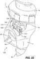
- the pushbutton 25 When the pushbutton 25 is pressed as shown in Fig. 22 , the pushbutton pin 25a engages the latch lever push bar 236 which moves in the direction of arrow "A" seen in Fig. 17 .
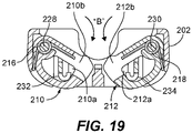
- the latch lever 214 pivots, the latch lever arms 232 and 234 pivot causing the latches 210 and 212 to rotate in the direction of arrow "B", seen in Fig. 19 , toward the plug release position.
- the plug release position seen in Figs.
- the latches 210 and 212 do not block the indexing rib portal 220 allowing the indexing rib 1 c to pass through the indexing rib portal 220.
- the shroud 1a of the plug 1 begins to move away from the retaining clips 7 allowing the retaining clips to return to their relaxed state.
- the ground contact pin 1e of the plug 1 disengages from the ground sleeve assembly 17 thus maintaining an electrical ground connection until after the line contact pins 1b separate from the contact sleeves 8.
- a latch assembly for capturing a plug relative to a receptacle comprising, a housing having a latch compartment and a latch lever compartment; a plurality of latches positioned within the latch compartment of the housing and rotatable between a plug capture position and a plug release position; a latch lever pivotably positioned at least partially within the latch lever compartment, the latch lever having a plurality of latch lever arms wherein one latch lever arm corresponds to one of the plurality of latches; and wherein the plurality of latch lever arms extend into the latch compartment and are operatively coupled to the corresponding latch such that pivotable movement of the latch lever is translated to rotational movement of the latches between the plug capture position and the plug release position.
- the plurality of latches comprises two latches. Each of the two latches are rotatably positioned within the latch compartment with a pivot pin and a spring normally biases each latch to the plug capture position. Each of the plurality of latches has an opening and wherein each latch lever arm is positioned within the respective opening to operatively couple the latch lever arm to the latch.
- the housing further comprises a portal between an exterior of the housing and the latch lever compartment and positioned relative to the plug capture position.
- a latch assembly for capturing a plug relative to a receptacle comprising, a housing having a latch compartment and a latch lever compartment; first and second latches positioned within the latch compartment and rotatable between a plug capture position and a plug release position; a latch lever pivotably positioned at least partially within the latch lever compartment, the latch lever having first and second latch lever arms; and wherein the first latch lever arm extends into the latch compartment and is operatively coupled to the first latch, and the second latch lever arm extends into the latch compartment and is operatively coupled to the second latch, such that pivotable movement of the latch lever is translated to rotational movement of the first and second latches between the plug capture position and the plug release position.
- the first latch is rotatably positioned within the latch compartment with a pivot pin and a first spring normally biases the first latch to the plug capture position
- the second latch is rotatably positioned within the latch compartment with a pivot pin and a second spring normally biases the second latch to the plug capture position.
- the first latch has an opening and the first latch lever arm is operatively coupled to the first latch by positioning the first latch lever arm in the opening.
- the second latch has an opening and the second latch lever arm is operatively coupled to the second latch by positioning the second latch lever arm in the opening.
- the housing further comprises a portal between an exterior of the housing and the latch lever compartment and positioned relative to the plug capture position.
- a pin-in-sleeve type electrical connector comprising, a plug having one or more electrically conductive contacts; and a receptacle configured to couple to the plug, the receptacle comprising: one or more electrically conductive contacts capable of mating with the one or more electrically conductive contacts in the plug such that one electrically conductive contact in the plug mates with one electrically conductive contact in the receptacle; and a latch assembly for capturing a plug relative to a receptacle, the latch assembly comprising: a housing having a latch compartment and a latch lever compartment; a plurality of latches positioned within the latch compartment of the housing and rotatable between a plug capture position and a plug release position; a latch lever pivotably positioned at least partially within the latch lever compartment, the latch lever having a plurality of latch lever arms wherein one latch lever arm corresponds to one of the plurality of latches; and wherein the plurality of latch lever arms extend into the latch compartment and are operatively coupled to the
- the plurality of latches comprises two latches. Each of the two latches are rotatably positioned within the latch compartment with a pivot pin and a spring normally biases each latch to the plug capture position. Each of the plurality of latches has an opening and wherein each latch lever arm is positioned within the respective opening to operatively couple the latch lever arm to the latch.
- the housing further comprises a portal between an exterior of the housing and the latch lever compartment and positioned relative to the plug capture position.
- a pin-in-sleeve type electrical connector comprising, a plug having one or more electrically conductive contacts; and a receptacle configured to couple to the plug, the receptacle comprising: one or more electrically conductive contacts capable of mating with the one or more electrically conductive contacts in the plug, such that one electrically conductive contact in the plug mates with one electrically conductive contact in the receptacle; and a latch assembly for capturing a plug relative to a receptacle, the latch assembly comprising: a housing having a latch compartment and a latch lever compartment; first and second latches positioned within the latch compartment and rotatable between a plug capture position and a plug release position; a latch lever pivotably positioned at least partially within the latch lever compartment, the latch lever having first and second latch lever arms; and wherein the first latch lever arm extends into the latch compartment and is operatively coupled to the first latch and the second latch lever arm extends into the latch compartment and is operatively coupled to the second latch, such
- the first latch is rotatably positioned within the latch compartment with a pivot pin and a first spring normally biases the first latch to the plug capture position
- the second latch is rotatably positioned within the latch compartment with a pivot pin and a second spring normally biases the second latch to the plug capture position.
- the first latch has an opening and the first latch lever arm is operatively coupled to the first latch by positioning the first latch lever arm in the opening.
- the second latch has an opening and the second latch lever arm is operatively coupled to the second latch by positioning the second latch lever arm in the opening.
- the housing further comprises a portal between an exterior of the housing and the latch lever compartment and positioned relative to the plug capture position.
- Additions could include additional or other types of arrangements that provide an audible or visible indication of the activation of the latch assembly of the present disclosure.
- the receptacle could have a visual indicator such as a sliding or rotating colored panel or a colored sleeve collar riding over a colored drum or sphere.
- a movable colored outer panel or surface covers an inner panel or surface, a contrasting color could be used to designate the changing state of power.
- an LED could be provided to indicate that the indexing tab 1 c is locked within the latch assembly of the present disclosure.
Landscapes
- Details Of Connecting Devices For Male And Female Coupling (AREA)
Abstract
Description
- The present application is based on and claims benefit from co-pending
U.S. Application Serial No. 15/298,114 filed October 19, 2016 - The present disclosure relates to electrical connectors, and in particular to pin-and-sleeve type electrical connectors.
- Standard pin and sleeve devices typically have a male plug with contact pins and a female receptacle with mating sleeve-like contacts sometimes called contact sleeves. Some form of plug-to-receptacle latching is usually provided at least to minimize accidental separation of the male plug from the female receptacle. The electrical connection is made through the mechanical insertion of the contact pins in the male plug into the contact sleeves in the female receptacle. For safety, the receptacle's contact sleeves may not be energized or accessible until the plug and receptacle are properly coupled.
- The present disclosure provides a latch assembly for locking a plug to a receptacle in pin-and-sleeve type electrical connectors. In one exemplary embodiment, the latch assembly includes a housing, plurality of latches, a latch lever and a plurality of latch lever arms extending from the latch lever such that one latch lever arm is operatively coupled to one latch. The housing has a latch compartment and a latch lever compartment. The plurality of latches are positioned within the latch compartment of the cover and rotatable between a plug capture position and a plug release position. The latch lever is pivotably positioned at least partially within the latch lever compartment. In this configuration pivotable movement of the latch lever is translated to rotational movement of the latches between the plug capture position and the plug release position.
- In another exemplary embodiment, the latch assembly includes a housing, first and second latches, a latch lever, and first and second latch lever arms extending from the latch lever such that the first latch lever arm is operatively coupled to the first latch, and the second latch lever arm is operatively coupled to the second latch. The housing has a latch compartment and a latch lever compartment, and the first and second latches are positioned within the latch compartment and rotatable between a plug capture position and a plug release position. The latch lever is pivotably positioned at least partially within the latch lever compartment. In this exemplary embodiment, the first latch lever arm extends into the latch compartment and is operatively coupled to the first latch, and the second latch lever arm extends into the latch compartment and is operatively coupled to the second latch. As such, pivotable movement of the latch lever can be translated to rotational movement of the first and second latches between the plug capture position and the plug release position.
- The latch assembly of the present disclosure shortens the displacements and force required to release the plug from the receptacle. This is achieved by lessening the deflection requirements for the latches.
- The present disclosure also provides pin-and-sleeve type electrical connectors that have a plug that can be coupled to a receptacle. The receptacle of the electrical connectors include the latch assembly described above.
- Embodiments of the invention are described in detail below, purely by way of example, with reference to the accompanying drawing figures, in which:
-
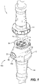
Fig. 1 is a perspective view of an exemplary configuration of an electrical connector according to the present disclosure, illustrating a plug and a receptacle; -
Fig. 2 is an enlarged perspective view of the electrical connector ofFig. 1 with a cut-out within the receptacle showing a latch assembly according to the present disclosure supported within the receptacle; -
Fig. 3 is an exploded perspective view of the receptacle ofFig. 1 ; -
Fig. 4 is an enlarged view of a portion of an upper housing of the receptacle ofFig. 3 and showing the positioning of the latch assembly relative to the receptacle housing; -
Fig. 5 is a perspective view of a sleeve carrier assembly of the receptacle ofFig. 3 , illustrating two retaining mechanisms associated with the assembled sleeve carrier housing; -
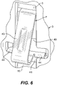
Fig. 6 is an enlarged perspective view of a retaining mechanism of the sleeve carrier assembly ofFig. 5 ; -
Fig. 7 is a sectional view of a portion of the sleeve carrier assembly ofFig. 5 in the area of one retaining mechanism; -
Fig. 8 is a bottom perspective view of a terminal retainer secured to an upper housing of the receptacle ofFig. 3 ; -
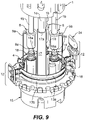
Fig. 9 is a perspective view of a portion of the plug ofFig. 2 and receptacle ofFig. 3 with parts removed to show pin contacts of the plug mating with contact sleeves of the sleeve carrier assembly and to show status indicator assemblies; -
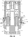
Fig. 10 is a sectional view through the sleeve carrier assembly of the receptacle ofFig. 3 showing the contact sleeves separated from corresponding contact terminals; -
Fig. 11 is a sectional view through the sleeve carrier assembly similar toFig. 10 and showing the contact sleeves engaging the corresponding contact terminals; -
Fig. 12 is a side elevational view in partial cross-section of the sleeve carrier assembly of the receptacle ofFig. 3 and a portion of the plug ofFig. 1 , showing a ground contact pin of the plug mating with a ground sleeve assembly of the receptacle; -
Fig. 13 is an exploded perspective view of the latch assembly according to the present disclosure; -
Fig. 14 is a rear perspective view of the latch assembly ofFig. 13 with the latch assembly in a plug capture position where movable latches block an indexing rib portal; -
Fig. 15 is a front perspective view of the latch assembly ofFig. 14 ; -
Fig. 16 is a top sectional view of the latch assembly ofFig. 14 ; -
Fig. 17 is a rear perspective view of the latch assembly according ofFig. 13 with the latch assembly in a plug release position where the movable latches do not block the indexing rib portal; -
Fig. 18 is a front perspective view of the latch assembly ofFig. 17 ; -
Fig. 19 is a top sectional view of the latch assembly ofFig. 17 ; -
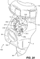
Fig. 20 is a perspective view of a portion of the electrical assembly ofFig. 2 , showing an indexing rib on the plug adjacent the indexing rib portal within the latch assembly ofFig. 13 , where the latch assembly is in the plug capture position prior to full insertion of the plug into the receptacle; -
Fig. 21 is a perspective view of the electrical assembly ofFig. 20 , showing the latch assembly in plug release position allowing the indexing rib on the plug to pass through the indexing rib portal when the plug is fully inserted into the receptacle; -
Fig. 22 is a perspective view of the electrical assembly ofFig. 21 , showing a pushbutton on the receptacle being depressed to cause the latch assembly to move from the plug capture position to the plug release position to facilitate withdrawal of the plug from the receptacle; and -
Fig. 23 is a perspective view of the electrical assembly ofFig. 22 , showing the pushbutton on the receptacle depressed and showing the latch assembly in the plug release position and the indexing tab passing through the latch assembly as the plug is being withdrawn from the receptacle. - As used in this application, terms such as "front," "rear," "side," "top," "bottom," "above," "below," "upwardly" and "downwardly" are intended to facilitate the description of the electrical connector and latch assembly according to the present disclosure and are not to be construed as limiting the structure of the electrical connector and latch assembly to any particular position or orientation.
- Referring to
Fig. 1 , amale plug 1 for mating with afemale receptacle 100 of a pin-and-sleeve type electrical connector is shown. As used in this application, the term plug relates to a male half of a pin-and-sleeve electrical connector, and the term "receptacle" relates to a female half of a pin-and-sleeve electrical connector regardless of how the receptacle is mounted, e.g., surface mounted, in-wall mounted or panel mounted, or how the receptacle is connected to a power source, e.g., connected to a power source via a cable. However, it should be readily appreciated that the plug may be a female half of the pin-in-sleeve electrical connector, and the receptacle may be a male half of the pin-in-sleeve electrical connector. A more detailed description of the components of anexemplary plug 1 andreceptacle 100, except for the latching assembly described herein, are described in commonly ownedU.S. Patent No. 9,252,539 plug 1 andreceptacle 100 follows. - Referring to
Figs. 2-4 , theplug 1 has a cylindricalfront safety shroud 1a surrounding a plurality ofline contact pins 1b and arotatable locking ring 1d. In some embodiments, theshroud 1a may also surround aground contact pin 1e. Theline contact pins 1b within theplug 1 are adapted to mate withcontact sleeves 8 withinsleeve carrier 10 in thereceptacle 100. Theground contact pin 1e is adapted to mate with aground sleeve assembly 17. Theshroud 1a of theplug 1 has an integrally formed, radially projecting indexingrib 1c at its front end. The indexingrib 1c, which may be a tab, interacts with alatching assembly 200 of thereceptacle 100 as will be described in more detail below. The rotatable locking ring Id has two lugs (not shown) adapted to mate with two standard rampedlocking flanges 2a at the front end of anupper housing 2 of thereceptacle 100. A standard butted rubber gasket (not shown) seals the interface between theplug 1 and thereceptacle 100 when they are fully mated. - Referring to
Fig. 3 , thereceptacle 100 has anupper housing 2 and alower housing 36. Thelower housing 36 is secured to theupper housing 2 using, for example, screws 38 with an interposedsealing gasket 35 between the two housings. In one exemplary embodiment, thelower housing 36 can be configured for connection to a cable. In another exemplary embodiment, theupper housing 2 can be mated instead to various adapters (not shown) using screws to enable mounting of thereceptacle 100 on a surface, in a wall, in a panel, etc. A sleeve carrier assembly according to the present disclosure is positioned within thereceptacle 100 and includes asleeve carrier housing 3, asleeve carrier 10 with its internal components and aterminal retainer 15 with its internal components as described herein. - Referring to
Figs. 3 and 8 , an exemplary embodiment of a portion of the sleeve carrier assembly is shown. Threeline contact sleeves 8 of this exemplary embodiment are fixed in thesleeve carrier 10 by asleeve carrier cap 6 held in place byscrews 5. Thesleeve carrier 10 is positioned within thesleeve carrier housing 3 and axially movable within the sleeve carrier housing. Thesleeve carrier housing 3 is fixed in place within theupper housing 2 of thereceptacle 100 by abutting theterminal retainer 15 to the sleeve carrier housing and securing the terminal retainer within theupper housing 2 using mounting screws 21. Two helical carriage springs 11 are interposed between thesleeve carrier 10 and theterminal retainer 15 and used to bias thesleeve carrier 10 away from thepressure contacts 18. - Referring now to
Figs. 3 and9-11 , the threecontact sleeves 8 have inwardly facingelectrical contact tips 8a that are axially movable into and out of engagement with a correspondingelectrical contact tip 18a of an equal number of braided, spring-loadedcontact terminals 18. Thecontact terminals 18 may also be referred to herein as "pressure contacts." Thecontact tips pressure contacts 18 are conventional electrical contacts, examples of which are described inU.S. Patent No. 4,176,905 , which is incorporated herein in its entirety by reference. Thepressure contacts 18 are supported in aterminal retainer 15 by aterminal retainer cap 19 fastened to theterminal retainer 15 byscrews 20. Theterminal retainer 15 is secured to theupper housing 2 usingscrews 21, as noted above, to secure the carrier sleeve assembly within thereceptacle 100. - Referring to
Figs. 3, 5 ,9 and12 , thereceptacle 100 may also include a continuous ground configuration that ensures grounding of the primary electrical circuit when inserting and withdrawing theplug 1 relative to thereceptacle 100. In embodiments where a continuous ground configuration is provided, aground sleeve assembly 17 is fixed in theterminal retainer 15 and extends freely throughsleeve carrier 10 where adistal end 17a of theground sleeve assembly 17 begins to mate with aground contact pin 1e of aplug 1 upon initial insertion of the plug into thereceptacle 100 and before theline contact sleeves 8 mate with their respectiveline contact pins 1b. In this exemplary embodiment, theground sleeve assembly 17, unlike theline contact sleeves 8, is not supported in or moved bysleeve carrier 10 and has no electrical contact tip on its inner end. Thus, thesleeve carrier 10 moves along the fixedground sleeve assembly 17 such that the ground connection between theplug 1 and thereceptacle 100 does rely on a pressure contact. Upon withdrawal of theplug 1 from thereceptacle 100, theground contact pin 1e of theplug 1 is the last contact pin to disengage from theground sleeve assembly 17 maintaining an electrical path to ground during withdrawal of theplug 1 from thereceptacle 100. - Referring now to
Figs. 3 and5-7 , thesleeve carrier 10 is positioned within thesleeve carrier housing 3 and axially movable within the sleeve carrier housing as noted above. Thesleeve carrier housing 3 has two diametricallyopposed windows 40, seen inFig. 5 , that join respective narrowerlongitudinal slots 41 extending from therespective window 40 toward theterminal retainer 15. Theupper end 7a of two inwardly deflectable resilient retaining clips 7 are anchored in respective recesses 42 in thesleeve carrier 10, as shown inFig. 7 . Each retainingclip 7 has an inclined,ribbed ramp portion 43 and a pair of lateral wings or shoulders 44. The retaining clips 7 may include a cover made of a thermoplastic material, such as Polyoxymethylene which may be sold for example under the name Delrin®. When the retainingclips 7 are in a relaxed state (not deflected), theramp portions 43 project outward through theirrespective window 40 in thecarrier housing 3 and theshoulders 44 engage the lower edges of theirrespective window 40, as shown inFig. 7 . In this relaxed state, theshoulders 44 of the retainingclips 7 prevent downward movement of thesleeve carrier 10 relative to thecarrier housing 3 keeping thecontact sleeves 8 separated from the pressure contacts 18 (seen for example inFig. 10 ). In addition, in the relaxed state theramp portions 43 of the retainingclips 7 project into the path traveled by theplug shroud 1a of theplug 1 when the plug is mated with thereceptacle 100. - Turning now to
Figs. 8 and9 , thereceptacle 100 also includes a modular clocking design that enables variable angular positioning of theterminal retainer 15 within theupper housing 2 so that a variety of terminal contact configurations can be achieved when manufacturing thereceptacle 100 without having to stock differently configured terminal retainers. In the exemplary embodiment shown, theupper housing 2 has a clocking key 50 facing the periphery ofterminal retainer 15, which has a plurality ofperipheral clocking knockouts 51. Theappropriate clocking knockout 51 is broken out during assembly of thereceptacle 100 depending on the terminal configuration specified for the unit. In this way, theterminal retainer 15 and thus thepressure contacts 18 can be adjusted to align with theline contact sleeves 8 and thecontact sleeve openings sleeve carrier housing 3, seen inFig. 5 , and theground sleeve assembly 17 can be aligned with theground contact opening 3d in the sleeve carrier housing. - Referring to
Figs. 3 and9 , thereceptacle 100 may also include a status indicator assembly that uses the primary power circuit to power a low-current lighting control circuit. The status indicator assembly includes first andsecond bridge connectors contact ring holders 14 and printed circuit board (PCB)assemblies 12. Thefirst bridge connector 9a is connected at one end to aline contact sleeve 8 and at another end to thetop connection clip 4. Thetop connection clip 4 is connected to thetop contact ring 13a thus forming an electrically conductive path between theline contact sleeve 8 and thetop contact ring 13a. Similarly, thesecond bridge connector 9b is connected at one end to anotherline contact sleeve 8 and at another end to thebottom connection clip 16. Thebottom connection clip 16 is connected to thebottom contact ring 13b thus forming an electrically conductive path between theline contact sleeve 8 and thebottom contact ring 13b. The contact rings 13a and 13b can be cylindrical rings that may be of unitary construction or that may have two halves. Eachcontact ring terminal retainer 15 usingcontact ring holder 14. EachPCB assembly 12 may be a plug-in type PCB that includes an integral LED or other lighting element and a lighting control circuit to illuminate the LED. The PCB is held in place by thecontact ring holder 14 and the lighting control circuit on the PCB is connected to and supported by the top and bottom contact rings 13a and 13b. EachPCB assembly 12 also includes anLED lens 24 and an interposedlens gasket 23, seen inFigs. 3 and9 . In this exemplary embodiment, closure of the primary electrical circuit occurs upon the full engagement of theplug 1 to thereceptacle 100. Closure of the primary electrical circuit also completes the lighting control circuit energizing the LEDs. The illuminated LEDs are visible throughobservation windows 52 on opposite sides ofupper housing 2, seen in for exampleFigs. 1 and3 , providing a visual indication that power is being supplied between theplug 1 and thereceptacle 100. - Referring again to
Figs. 2-4 , thereceptacle 100 also includes apushbutton assembly 150 having apushbutton 25 that is sealed to theupper housing 2 by abutton seal cup 27 and abutton lip seal 28. Thepushbutton 25 has apushbutton pin 25a that passes through aspring 26, thebutton seal cup 27, thebutton lip seal 28 and extends through theupper housing 2 into alatch assembly pocket 2b in the upper housing, as seen inFig. 2 . Thespring 26 normally biases thepushbutton 25 away from theupper housing 2. Thepushbutton assembly 150 is surrounded on three sides by aU-shaped rim 48 integrally formed into theupper housing 2. Therim 48 protects thepushbutton assembly 150 from damage while providing sufficient space in the recess around thepushbutton 25 to keep dust and debris from accumulating in that region. - The
latch assembly pocket 2b in theupper housing 2 supports a latchingassembly 200 that interacts with theindexing rib 1c of theplug 1 and thepushbutton assembly 150 during coupling and decoupling of theplug 1 relative to thereceptacle 100. The latchingassembly 200 selectively permits or inhibits decoupling movement of theplug 1 relative to thereceptacle 100, and may provide a positive and audible engagement of theplug 1 as it mates with thereceptacle 100. A more detailed description of the latchingassembly 200 according to the present disclosure and its operation will be described. - Referring to
Figs. 2 and13 , an exemplary configuration of thelatch assembly 200 of the present disclosure is shown. Thelatch assembly 200 includes alatch assembly housing 202, a pair of rotating (or pivoting) latches 210 and 212, and latchlever 214. Thelatch assembly housing 202 is supported within thepocket 2b of theupper housing 2, as noted above and as shown inFig. 4 . Thelatch assembly housing 202 has alatch compartment 222 configured to receive thelatches corresponding springs latch assembly housing 202 also has alatch lever compartment 224 configured to receive thelatch lever 214. Thelatch assembly housing 202 also has anindexing rib portal 220 that provides an entry to thelatch compartment 222 and thelatch lever compartment 224. - The
latch 210 is secured within thelatch compartment 222 usinglatch pivot pin 228 so that thelatch 210 can rotate between the plug capture position, seen inFigs. 14-16 , and the plug release position, seen inFigs. 17-19 . Similarly, thelatch 212 is secured within thelatch compartment 222 usinglatch pivot pin 230 so that thelatch 212 can rotate between the plug capture position and the plug release position. Thelatches respective springs latches indexing rib portal 220, as seen inFigs. 14-16 . - The
latch lever 214 is secured within thelatch lever compartment 224 usinglatch lever pin 226 so that thelatch lever 214 is pivotable within thelatch lever compartment 224 relative to thelatch assembly housing 202. Thelatch lever 214 includeslatch lever arms lever push bar 236.Latch lever arm 232 passes through thelatch lever compartment 224 into thelatch compartment 222 and fits withinaperture 210a inlatch 210. Similarly, thelatch lever arm 234 passes through thelatch lever compartment 224 into thelatch compartment 222 and fits withinaperture 212a inlatch 212. As a result, pivotable movement of thelatch lever 214 caused when a force is applied to the latchlever push bar 236 is translated to rotational movement of thelatches - As noted above, the
latch 210 is normally biased toward the plug capture position bytorsion spring 216, and thelatch 212 is normally biased toward the plug-capture position bytorsion spring 218, as seen inFig. 16 . Thelatch assembly 200 of the present disclosure reduces the force to be applied to thepushbutton 25 and the pushbutton stroke deflection in order to decouple theplug 1 from thereceptacle 100. As an example, the force needed to decouple theplug 1 from thereceptacle 100 can, for example, range from about 10 lbs. to about 25 lbs. Further, the deflection stroke of thepushbutton 25 which translates pivotable movement of thelatch lever 214 to rotational movement of thelatches indexing rib portal 220. For example, an angle of rotation of eachlatch indexing rib portal 220 so that theindexing rib 1c can pass through the latchingassembly 200. - Mechanical and electrical coupling and decoupling of the
plug 1 relative to thereceptacle 100 is accomplished by axial motion of the plug as it is inserted into or withdrawn from thereceptacle 100. Inward axial motion of theplug 1 into thereceptacle 100 triggers a sequence of movements of the internal components within thereceptacle 100 to first mechanically couple theplug 1 to thereceptacle 100 and then electrically couple theplug 1 to thereceptacle 100. More specifically, as the line contact pins 1b and theground contact pin 1e of theplug 1 are pressed into thereceptacle 100, theground contact pin 1e first engages theground sleeve assembly 17. Further mating of theplug 1 with thereceptacle 100 causes the line contact pins 1b to mate with and press into therespective contact sleeves 8 of thereceptacle 100. With this mechanical coupling of theplug 1 to thereceptacle 100, thecontact sleeves 8 and thesleeve carrier 10 are held in position relative to thesleeve carrier housing 3 by the retainingclips 7, even as the leading edge of the plug shroud la begins to deflect the clips radially inward in the direction of arrow "C", as seenFig. 7 . When the line contact pins 1b of theplug 1 are substantially fully seated in thecontact sleeves 8 the retainingclips 7 have been deflected by theshroud 1a of theplug 1 to the point that theshoulders 44 of theclips 7 have cleared the edges of thewindows 40 in thesleeve carrier housing 3, freeing thesleeve carrier 10 to move downward relative to thesleeve carrier housing 3 in the direction of thepressure contacts 18. - In addition, and referring to
Figs. 20 and21 , further insertion of theplug 1 into thereceptacle 100 pushes thesleeve carrier 10 and thecontact sleeves 8 toward thepressure contacts 18 compressing the carriage return springs 11. As this occurs, theindexing rib 1c of theplug 1contacts camming surfaces latches latches latches index rib 1c can pass through theindexing rib port 220 into thelatch compartment 222 and into thelatch lever compartment 224. When theindexing rib 1c passes thelatches indexing rib 1c on the camming surfaces 210b and 212b is removed. As a result, thelatches Fig. 16 , capturing theindexing rib 1c within thelatch assembly 200. In this state, the line contact pins 1b of theplug 1 are fully seated in thecontact sleeves 8 of thereceptacle 100 and thecontact tips 8a of the contact sleeves are in electrical contact withcontact tips 18a of thepressure contacts 18, as seen inFig. 11 , within thereceptacle 100 providing primary electrical power to theplug 1. In addition, if theplug 1 andreceptacle 100 include aground pin 1e andground sleeve assembly 17, the ground contact pin of the plug is within the ground sleeve assembly to provide an electrical path to ground. - Decoupling of the
plug 1 from thereceptacle 100 is illustrated inFigs. 22 and23 . When thepushbutton 25 is pressed as shown inFig. 22 , thepushbutton pin 25a engages the latchlever push bar 236 which moves in the direction of arrow "A" seen inFig. 17 . As thelatch lever 214 pivots, thelatch lever arms latches Fig. 19 , toward the plug release position. In the plug release position, seen inFigs. 17-19 , thelatches indexing rib portal 220 allowing theindexing rib 1c to pass through theindexing rib portal 220. Axial movement of theplug 1 away from thereceptacle 100, as shown inFig. 23 , allows theplug 1 to be decoupled from thereceptacle 100. - While the
plug 1 is being withdrawn from thereceptacle 100, a sequence of movements of the internal components within thereceptacle 100 are triggered to electrically decouple theplug 1 from thereceptacle 100. More specifically, as the plug is being withdrawn from thereceptacle 100, the return springs 11 retract thesleeve carrier 10 back towards thesleeve carrier housing 3. This action separates thecontact sleeves 8 from thepressure contacts 18 to break the primary electrical path between the plug and the receptacle. As theplug 1 is further withdrawn from thereceptacle 100 the line contact pins 1b of theplug 1 begin to separate from theirrespective contact sleeves 8. At around the same time, theshroud 1a of theplug 1 begins to move away from the retainingclips 7 allowing the retaining clips to return to their relaxed state. As theplug 1 is further withdrawn from thereceptacle 100 theground contact pin 1e of theplug 1 disengages from theground sleeve assembly 17 thus maintaining an electrical ground connection until after the line contact pins 1b separate from thecontact sleeves 8. - A latch assembly for capturing a plug relative to a receptacle, the latch assembly comprising, a housing having a latch compartment and a latch lever compartment; a plurality of latches positioned within the latch compartment of the housing and rotatable between a plug capture position and a plug release position; a latch lever pivotably positioned at least partially within the latch lever compartment, the latch lever having a plurality of latch lever arms wherein one latch lever arm corresponds to one of the plurality of latches; and wherein the plurality of latch lever arms extend into the latch compartment and are operatively coupled to the corresponding latch such that pivotable movement of the latch lever is translated to rotational movement of the latches between the plug capture position and the plug release position.
- The plurality of latches comprises two latches. Each of the two latches are rotatably positioned within the latch compartment with a pivot pin and a spring normally biases each latch to the plug capture position. Each of the plurality of latches has an opening and wherein each latch lever arm is positioned within the respective opening to operatively couple the latch lever arm to the latch. The housing further comprises a portal between an exterior of the housing and the latch lever compartment and positioned relative to the plug capture position.
- A latch assembly for capturing a plug relative to a receptacle, the latch assembly comprising, a housing having a latch compartment and a latch lever compartment; first and second latches positioned within the latch compartment and rotatable between a plug capture position and a plug release position; a latch lever pivotably positioned at least partially within the latch lever compartment, the latch lever having first and second latch lever arms; and wherein the first latch lever arm extends into the latch compartment and is operatively coupled to the first latch, and the second latch lever arm extends into the latch compartment and is operatively coupled to the second latch, such that pivotable movement of the latch lever is translated to rotational movement of the first and second latches between the plug capture position and the plug release position.
- The first latch is rotatably positioned within the latch compartment with a pivot pin and a first spring normally biases the first latch to the plug capture position, and wherein the second latch is rotatably positioned within the latch compartment with a pivot pin and a second spring normally biases the second latch to the plug capture position. The first latch has an opening and the first latch lever arm is operatively coupled to the first latch by positioning the first latch lever arm in the opening. The second latch has an opening and the second latch lever arm is operatively coupled to the second latch by positioning the second latch lever arm in the opening. The housing further comprises a portal between an exterior of the housing and the latch lever compartment and positioned relative to the plug capture position.
- A pin-in-sleeve type electrical connector comprising, a plug having one or more electrically conductive contacts; and a receptacle configured to couple to the plug, the receptacle comprising: one or more electrically conductive contacts capable of mating with the one or more electrically conductive contacts in the plug such that one electrically conductive contact in the plug mates with one electrically conductive contact in the receptacle; and a latch assembly for capturing a plug relative to a receptacle, the latch assembly comprising: a housing having a latch compartment and a latch lever compartment; a plurality of latches positioned within the latch compartment of the housing and rotatable between a plug capture position and a plug release position; a latch lever pivotably positioned at least partially within the latch lever compartment, the latch lever having a plurality of latch lever arms wherein one latch lever arm corresponds to one of the plurality of latches; and wherein the plurality of latch lever arms extend into the latch compartment and are operatively coupled to the corresponding latch such that pivotable movement of the latch lever is translated to rotational movement of the latches between the plug capture position and the plug release position.
- The plurality of latches comprises two latches. Each of the two latches are rotatably positioned within the latch compartment with a pivot pin and a spring normally biases each latch to the plug capture position. Each of the plurality of latches has an opening and wherein each latch lever arm is positioned within the respective opening to operatively couple the latch lever arm to the latch. The housing further comprises a portal between an exterior of the housing and the latch lever compartment and positioned relative to the plug capture position.
- A pin-in-sleeve type electrical connector comprising, a plug having one or more electrically conductive contacts; and a receptacle configured to couple to the plug, the receptacle comprising: one or more electrically conductive contacts capable of mating with the one or more electrically conductive contacts in the plug, such that one electrically conductive contact in the plug mates with one electrically conductive contact in the receptacle; and a latch assembly for capturing a plug relative to a receptacle, the latch assembly comprising: a housing having a latch compartment and a latch lever compartment; first and second latches positioned within the latch compartment and rotatable between a plug capture position and a plug release position; a latch lever pivotably positioned at least partially within the latch lever compartment, the latch lever having first and second latch lever arms; and wherein the first latch lever arm extends into the latch compartment and is operatively coupled to the first latch and the second latch lever arm extends into the latch compartment and is operatively coupled to the second latch, such that pivotable movement of the latch lever is translated to rotational movement of the first and second latches between the plug capture position and the plug release position.
- The first latch is rotatably positioned within the latch compartment with a pivot pin and a first spring normally biases the first latch to the plug capture position, and wherein the second latch is rotatably positioned within the latch compartment with a pivot pin and a second spring normally biases the second latch to the plug capture position. The first latch has an opening and the first latch lever arm is operatively coupled to the first latch by positioning the first latch lever arm in the opening. The second latch has an opening and the second latch lever arm is operatively coupled to the second latch by positioning the second latch lever arm in the opening. The housing further comprises a portal between an exterior of the housing and the latch lever compartment and positioned relative to the plug capture position.
- While exemplary embodiments have been chosen to illustrate the invention, it will be understood by those skilled in the art that various changes, modifications, additions, and substitutions are possible, without departing from the scope and spirit of the invention. Additions could include additional or other types of arrangements that provide an audible or visible indication of the activation of the latch assembly of the present disclosure. For example, the receptacle could have a visual indicator such as a sliding or rotating colored panel or a colored sleeve collar riding over a colored drum or sphere. Where a movable colored outer panel or surface covers an inner panel or surface, a contrasting color could be used to designate the changing state of power. As another example, an LED could be provided to indicate that the
indexing tab 1c is locked within the latch assembly of the present disclosure.
Claims (15)
- A latch assembly for capturing a plug relative to a receptacle, the latch assembly comprising:a housing having a latch compartment and a latch lever compartment;first and second latches positioned within the latch compartment and rotatable between a plug capture position and a plug release position;a latch lever pivotably positioned at least partially within the latch lever compartment, the latch lever having first and second latch lever arms; andwherein the first latch lever arm extends into the latch compartment and is operatively coupled to the first latch, and the second latch lever arm extends into the latch compartment and is operatively coupled to the second latch, such that pivotable movement of the latch lever is translated to rotational movement of the first and second latches between the plug capture position and the plug release position.
- The latch assembly according to claim 1, wherein the first latch is rotatably positioned within the latch compartment with a pivot pin and a first spring normally biases the first latch to the plug capture position, and wherein the second latch is rotatably positioned within the latch compartment with a pivot pin and a second spring normally biases the second latch to the plug capture position.
- The latch assembly according to claim 1, wherein the first latch has an opening and the first latch lever arm is operatively coupled to the first latch by positioning the first latch lever arm in the opening, and wherein the second latch has an opening and the second latch lever arm is operatively coupled to the second latch by positioning the second latch lever arm in the opening.
- The latch assembly according to claim 1, wherein the housing further comprises a portal between an exterior of the housing and the latch lever compartment and positioned so that the first and second latches block the portal when in the plug capture position.
- The latch assembly according to claim 1, wherein the first and second latches are positioned substantially within the same latch compartment and rotatable within the same latch compartment between the plug capture position and the plug release position.
- The latch assembly according to claim 1, wherein the first and second latches including respective camming surfaces, wherein when a force is exerted on the camming surfaces the first and second latches rotate from the plug capture position to the plug release position.
- The latch assembly according to claim 6, wherein the camming surfaces are disposed on top of the first and second latches.
- The latch assembly according to claim 6, wherein the first and second latches automatically return to the plug capture position from the plug release position when the exerting force is removed from the camming surfaces.
- A pin-in-sleeve type electrical connector comprising,a plug having one or more electrically conductive contacts; anda receptacle configured to couple to the plug, the receptacle comprising:
one or more electrically conductive contacts capable of mating with the one or more electrically conductive contacts in the plug, such that one electrically conductive contact in the plug mates with one electrically conductive contact in the receptacle; anda latch assembly for capturing a plug relative to a receptacle, the latch assembly comprising:a housing having a latch compartment and a latch lever compartment;first and second latches positioned within the latch compartment and rotatable between a plug capture position and a plug release position;a latch lever pivotably positioned at least partially within the latch lever compartment, the latch lever having first and second latch lever arms; andwherein the first latch lever arm extends into the latch compartment and is operatively coupled to the first latch and the second latch lever arm extends into the latch compartment and is operatively coupled to the second latch, such that pivotable movement of the latch lever is translated to rotational movement of the first and second latches between the plug capture position and the plug release position. - The latch assembly according to claim 9, wherein the first latch is rotatably positioned within the latch compartment with a pivot pin and a first spring normally biases the first latch to the plug capture position, and wherein the second latch is rotatably positioned within the latch compartment with a pivot pin and a second spring normally biases the second latch to the plug capture position.
- The latch assembly according to claim 9, wherein the first latch has an opening and the first latch lever arm is operatively coupled to the first latch by positioning the first latch lever arm in the opening, and wherein the second latch has an opening and the second latch lever arm is operatively coupled to the second latch by positioning the second latch lever arm in the opening.
- The latch assembly according to claim 9, wherein the housing further comprises a portal between an exterior of the housing and the latch lever compartment and positioned so that the first and second latches block the portal when in the plug capture position.
- The electrical connector according to claim 9, wherein the plug further includes an indexing rib positioned to engage the first and second latches when the receptacle is coupled to the plug and used to releasably secure the receptacle to the plug.
- The electrical connector according to claim 13, wherein when the receptacle is coupled to the plug the indexing rib passes through the housing and exerts the force on the camming surfaces causing the first and second latches to rotate from the plug capture position to the plug release position allowing the indexing rib to pass into the latch lever compartment and permitting the first and second latches to automatically rotate from the plug release position to the plug capture position to capture the indexing rib in the latch lever compartment so that the receptacle is releasably secured to the plug.
- The electrical connector according to claim 13, wherein when the receptacle is to be decoupled from the plug, the latch lever is pivoted causing the first and second latches to rotate to the plug release position permitting the indexing rib to be removed from the housing.
Applications Claiming Priority (3)
| Application Number | Priority Date | Filing Date | Title |
|---|---|---|---|
| US15/298,114 US9887489B1 (en) | 2016-10-19 | 2016-10-19 | Electrical connector with plug latching assembly |
| PCT/US2017/054840 WO2018075231A1 (en) | 2016-10-19 | 2017-10-03 | Electrical connector with plug latching assembly |
| EP17862718.8A EP3529864B1 (en) | 2016-10-19 | 2017-10-03 | Electrical connector with plug latching assembly |
Related Parent Applications (1)
| Application Number | Title | Priority Date | Filing Date |
|---|---|---|---|
| EP17862718.8A Division EP3529864B1 (en) | 2016-10-19 | 2017-10-03 | Electrical connector with plug latching assembly |
Publications (1)
| Publication Number | Publication Date |
|---|---|
| EP4030567A1 true EP4030567A1 (en) | 2022-07-20 |
Family
ID=61027344
Family Applications (2)
| Application Number | Title | Priority Date | Filing Date |
|---|---|---|---|
| EP17862718.8A Active EP3529864B1 (en) | 2016-10-19 | 2017-10-03 | Electrical connector with plug latching assembly |
| EP22160502.5A Pending EP4030567A1 (en) | 2016-10-19 | 2017-10-03 | Electrical connector with plug latching assembly |
Family Applications Before (1)
| Application Number | Title | Priority Date | Filing Date |
|---|---|---|---|
| EP17862718.8A Active EP3529864B1 (en) | 2016-10-19 | 2017-10-03 | Electrical connector with plug latching assembly |
Country Status (5)
| Country | Link |
|---|---|
| US (2) | US9887489B1 (en) |
| EP (2) | EP3529864B1 (en) |
| CN (1) | CN109845045B (en) |
| CA (1) | CA3040682C (en) |
| WO (1) | WO2018075231A1 (en) |
Families Citing this family (16)
| Publication number | Priority date | Publication date | Assignee | Title |
|---|---|---|---|---|
| CN106998005A (en) * | 2016-01-22 | 2017-08-01 | 马要武 | Locking electrical outlets plug |
| US9887489B1 (en) * | 2016-10-19 | 2018-02-06 | Hubbell Incorporated | Electrical connector with plug latching assembly |
| WO2018231980A1 (en) * | 2017-06-13 | 2018-12-20 | Hubbell Incorporated | Locking electrical contact device with switch |
| WO2019040485A1 (en) | 2017-08-21 | 2019-02-28 | Hubbel Incorporated | Electrical contact device with interlock |
| CN117254284A (en) * | 2018-02-16 | 2023-12-19 | 康尔福盛303公司 | Modular connector for infusion pump system |
| US10330301B1 (en) * | 2018-04-17 | 2019-06-25 | Te Connectivity Corporation | Receptacle connector for a light sensor assembly for a light fixture |
| CA3110654A1 (en) * | 2018-08-29 | 2020-03-05 | Leviton Manufacturing Co., Inc. | Pin and sleeve device with indication |
| US12149019B2 (en) * | 2018-10-16 | 2024-11-19 | Leviton Manufacturing Co., Inc. | Pin and sleeve device with features to facilitate easier assembly |
| US10950966B2 (en) | 2018-10-26 | 2021-03-16 | American Mine Research, Inc. | Safety stab technology |
| FR3091049B1 (en) * | 2018-12-19 | 2021-01-15 | Schneider Electric Ind Sas | Electrical connection point |
| EP3745541B1 (en) * | 2019-05-31 | 2022-09-14 | ERICH JAEGER GmbH + Co. KG | Socket for a combined electrical connection and data connection |
| EP3823104A1 (en) * | 2019-11-12 | 2021-05-19 | TE Connectivity Nederland B.V. | Distribution automation device |
| CN211150950U (en) * | 2020-01-03 | 2020-07-31 | 康普技术有限责任公司 | Electrical connector assembly |
| WO2022005745A1 (en) * | 2020-07-01 | 2022-01-06 | Commscope Technologies Llc | Power cable connectors and assemblies |
| CA3219301A1 (en) * | 2022-11-08 | 2024-05-08 | 360 Two Pty Ltd | Electrical connector assembly |
| GB2625109A (en) * | 2022-12-07 | 2024-06-12 | Black & Decker Inc | A power tool and rotatable electrical connector therefor |
Citations (4)
| Publication number | Priority date | Publication date | Assignee | Title |
|---|---|---|---|---|
| US4176905A (en) | 1976-09-22 | 1979-12-04 | Societe d'Exploitation des Procedes Marechal SEPM | Flexible electrical contact |
| US5055057A (en) * | 1989-08-07 | 1991-10-08 | Boyer Paul L | Electric plug lock |
| US20140127926A1 (en) * | 2012-11-02 | 2014-05-08 | Hubbell Incorporated | Internally switched female receptacle or connector with plug-latching safety interlock |
| US20160141800A1 (en) * | 2014-11-14 | 2016-05-19 | GM Global Technology Operations LLC | Systems and methods for self-closing electrical connector |
Family Cites Families (71)
| Publication number | Priority date | Publication date | Assignee | Title |
|---|---|---|---|---|
| US2241828A (en) | 1938-06-17 | 1941-05-13 | Albert & J M Anderson Mfg Co | Electrical switch |
| FR2270696B1 (en) | 1974-03-14 | 1977-10-07 | Marechal Sepm | |
| FR2358032A1 (en) | 1976-07-09 | 1978-02-03 | Sepm Sa | IMPROVEMENTS TO CONNECTORS AND MORE PARTICULARLY TO CHARGING CONNECTORS |
| US4109095A (en) * | 1976-10-28 | 1978-08-22 | Mulberry Metal Products, Inc. | Weatherproof electrical outlet box cover |
| US4060297A (en) * | 1976-11-29 | 1977-11-29 | Marshall Bruce H | Plug cap |
| US4136919A (en) * | 1977-11-04 | 1979-01-30 | Howard Guy W | Electrical receptacle with releasable locking means |
| US4488765A (en) | 1980-06-18 | 1984-12-18 | The United States Of America As Represented By The Secretary Of The Navy | Dead-faced electrical connector with electromagnetic vulnerability protection |
| EP0106931B1 (en) | 1982-10-21 | 1986-04-30 | Société d'Exploitation des Procédés Maréchal S.E.P.M. (Société Anonyme) | Socket having a snap-action connection and disconnection |
| DE3371727D1 (en) | 1982-12-21 | 1987-06-25 | Legrand Sa | Electrical security socket, especially for an explosive atmosphere |
| US4553000A (en) | 1983-11-14 | 1985-11-12 | Appleton Electric Company | Plug and receptacle with separable switch contactors |
| DE3471408D1 (en) | 1984-12-27 | 1988-06-23 | Marechal Sepm | Receptacle, especially for power currents |
| US4784611A (en) | 1987-08-18 | 1988-11-15 | Poulin Fernand H | Locking plug |
| FR2623945B1 (en) | 1987-11-30 | 1990-04-27 | Marechal Sepm | POWER SOCKET WITH PRESSURE CONTACTS |
| US5071360A (en) | 1988-10-04 | 1991-12-10 | Lindow Edgar J | Permanently attachable key-activated on/off switch |
| US4925396A (en) | 1989-06-30 | 1990-05-15 | Grover Dennis L | Latching mechanism for electrical plugs |
| US5244409A (en) | 1990-07-12 | 1993-09-14 | Woodhead Industries, Inc. | Molded connector with embedded indicators |
| US5007857A (en) | 1990-07-30 | 1991-04-16 | Wright Duane E | Electrical receptacle with power indicator light |
| FR2680608B1 (en) | 1991-08-21 | 1993-10-08 | Marechal Expl Procedes | SELECTIVE DEVICE FOR ELECTRICAL CONNECTION PROVIDED WITH A SAFETY DISC AND A COMPLEMENTARY DISC. |
| GB2264201B (en) | 1992-02-13 | 1996-06-05 | Swift 943 Ltd | Electrical connector |
| FR2703844B1 (en) | 1993-04-09 | 1995-05-24 | Sepm | Electrical connector and more specifically charging connector. |
| US5503569A (en) | 1993-10-04 | 1996-04-02 | The Whitaker Corporation | Electrical connector with two stage latch for retaining contacts |
| USD369782S (en) | 1994-04-14 | 1996-05-14 | Yazaki Corporation | Connector shell for electric supplier for electric car |
| FR2727800B1 (en) | 1994-12-02 | 1997-01-17 | Marechal Sepm | WATERPROOF ELECTRICAL CONNECTION DEVICE |
| FR2746550B1 (en) | 1996-03-22 | 1998-04-24 | Marechal Sepm | WATERPROOF MOBILE ELECTRICAL OUTLET WITH PROTECTIVE SHUTTER |
| US5702266A (en) | 1996-05-03 | 1997-12-30 | Molex Incorporated | Electrical connector latching system |
| FR2749444B1 (en) | 1996-05-31 | 1998-07-24 | Marechal Sepm | WATERPROOF ELECTRICAL CONNECTION DEVICE |
| FR2756669B1 (en) | 1996-12-02 | 1998-12-31 | Marechal Sepm | ELECTRICAL CONNECTION DEVICE WITH LOCKING IN OPENING POSITION |
| US5893772A (en) * | 1997-08-27 | 1999-04-13 | Pacific Electricord Company | Locking mechanism for an electrical connector |
| FR2777120B1 (en) | 1998-04-07 | 2000-05-05 | Marechal Sepm | RING FOR IDENTIFYING THE OPERATING VOLTAGE OF AN ELECTRICAL CONNECTION ELEMENT |
| FR2777391B1 (en) | 1998-04-09 | 2000-06-23 | Carrier Kheops Bac | SAFETY HERMAPHRODITE ELECTRICAL CONNECTOR |
| FR2797720B1 (en) | 1999-07-30 | 2001-10-26 | Legrand Sa | CONTROLLED CURRENT DISTRIBUTION DEVICE WITH MECHANICAL LOCKING OF THE PLUG IN A CORRESPONDING BASE |
| US6382990B1 (en) | 1999-11-19 | 2002-05-07 | Societe D'exploitation Des Procedes Marechal (Sepm) | Electric connection base plate in particular for explosible environment and method for making same |
| FR2801432B1 (en) | 1999-11-19 | 2001-12-21 | Marechal Sepm | SOCKET BASE PROVIDED WITH A BELLOWS SEAL |
| US6255607B1 (en) | 1999-12-20 | 2001-07-03 | Hubbell Incorporated | Switchable receptacle assembly having internal interlock mechanism |
| EP1137115A3 (en) | 2000-01-25 | 2002-04-10 | AMPHENOL-TUCHEL ELECTRONICS GmbH | Electrical plug |
| FR2810804B1 (en) | 2000-06-22 | 2002-12-27 | Marechal Sepm | ELASTIC ELECTRICAL CONTACT WITH AXIAL PRESSURE AND WATERPROOF CONNECTION |
| FR2810803B1 (en) | 2000-06-22 | 2002-12-13 | Marechal Sepm | ELASTIC ELECTRICAL CONTACT AT AXIAL PRESSURE, WITH ORIENTABLE CONNECTION TERMINAL |
| DE20012400U1 (en) | 2000-07-18 | 2001-11-29 | Robert Bosch Gmbh, 70469 Stuttgart | Locking slide for connector parts of electrical connector elements |
| FR2812134B1 (en) | 2000-07-21 | 2002-12-13 | Marechal Sepm | AXIAL RETENTION DEVICE OF A CYLINDRICAL ELEMENT AND MORE PARTICULARLY A CABLE |
| JP2004079483A (en) | 2002-08-22 | 2004-03-11 | Sumitomo Wiring Syst Ltd | Connector |
| FR2848347B1 (en) | 2002-12-06 | 2005-01-07 | Marechal Sepm | ELASTIC RECALL ELECTRICAL CONTACT AND ELECTRICAL CONNECTING ELEMENT PROVIDED WITH AT LEAST ONE SUCH CONTACT |
| US6825417B2 (en) | 2003-01-31 | 2004-11-30 | Daimlerchrysler Corporation | Slide and snap cable end fitting |
| FR2855660B1 (en) | 2003-05-27 | 2005-08-19 | Marechal Sepm | ELECTRICAL CONNECTION DEVICE PROVIDED WITH AT LEAST ONE TUBULAR END CONTACT |
| US6783380B1 (en) * | 2003-06-11 | 2004-08-31 | Yazaki North America, Inc. | Low insertion force connector system |
| WO2005043689A1 (en) | 2003-10-03 | 2005-05-12 | Tyco Healthcare Group Lp | Cable terminal sealing facility |
| US6875040B1 (en) * | 2004-01-09 | 2005-04-05 | Pirana Plugs | Lockable electric power cord adapter |
| US7081024B2 (en) | 2004-09-01 | 2006-07-25 | Gensus | Electrical connector system and method involving positive mating and flex release |
| CA2540612A1 (en) | 2005-03-24 | 2006-09-24 | Bld Products, Ltd. | Electrical connector assembly |
| US7172451B1 (en) * | 2006-03-16 | 2007-02-06 | Inventor's Group Llc | Automatic locking electrical outlet |
| FR2898735A1 (en) | 2006-03-17 | 2007-09-21 | Marechal Sepm | ELECTRICAL CONNECTION ELEMENT SEALED |
| USD639741S1 (en) | 2006-03-29 | 2011-06-14 | Nuvasive, Inc. | Electrode connector |
| US7249976B1 (en) | 2006-03-30 | 2007-07-31 | Watson H Scott | Electrical plug, receptacle and switch |
| US8105106B1 (en) | 2006-06-10 | 2012-01-31 | James Marshall Stoddard | Disposable illuminated electrical plug adapter |
| US7452230B1 (en) * | 2006-06-27 | 2008-11-18 | Tmc Enterprises, A Division Of Tasco Industries, Inc. | Electrical cord plug assembly |
| US7422486B2 (en) | 2006-09-22 | 2008-09-09 | Itt Manufacturing Enterprises, Inc. | Connectors to connect modules to electronic devices |
| FR2909226A1 (en) | 2006-11-29 | 2008-05-30 | Procedes Marechal Sepm Sa Soc | Electrical connection device e.g. free coupler connector, has joint with stop surface cooperated with case surface such that sealing is ensured between socket and plug, where surfaces are slid during rotational movement of socket and plug |
| US8105356B2 (en) | 2007-06-05 | 2012-01-31 | Spartek Medical, Inc. | Bone anchor with a curved mounting element for a dynamic stabilization and motion preservation spinal implantation system and method |
| US8167638B2 (en) * | 2007-06-12 | 2012-05-01 | Panduit Corp. | Multi-position quick release plug cassette assembly |
| CN201038412Y (en) * | 2007-07-09 | 2008-03-19 | 维熹科技股份有限公司 | Female plug with anti-drop mechanism |
| US8011938B2 (en) | 2008-05-21 | 2011-09-06 | Tyco Electroniccs Corporation | Electrical connector having linear actuator |
| US7811115B1 (en) | 2008-12-12 | 2010-10-12 | Tyco Electronics Corporation | Connector assembly with two stage latch |
| USD648271S1 (en) | 2009-12-16 | 2011-11-08 | Harting Electric Gmbh & Co. Kg | Connection socket |
| US8882548B2 (en) | 2010-10-07 | 2014-11-11 | Thomas & Betts International Llc | Cam clamp for electrical connector |
| USD667791S1 (en) | 2011-01-18 | 2012-09-25 | Camco Manufacturing, Inc. | 30 amp right angle locking electrical head with handle |
| USD680494S1 (en) | 2011-05-10 | 2013-04-23 | Dai-Ichi Seiko Co., Ltd. | Electric connector |
| USD688629S1 (en) | 2011-07-20 | 2013-08-27 | Harting Electric Gmbh & Co. Kg | Connection socket |
| TWD150215S (en) | 2011-10-20 | 2012-11-11 | 第一精工股份有限公司 | Electric connector |
| US8772655B2 (en) | 2012-08-23 | 2014-07-08 | Chicony Power Technology Co., Ltd. | Receptacle structure and power adapter with the same |
| US8840418B2 (en) * | 2012-12-13 | 2014-09-23 | Chao-Chuan Chien | Socket structure capable of preventing plug from detaching |
| USD698320S1 (en) | 2013-03-28 | 2014-01-28 | Hubbell Incorporated | Electrical receptacle housing |
| US9887489B1 (en) * | 2016-10-19 | 2018-02-06 | Hubbell Incorporated | Electrical connector with plug latching assembly |
-
2016
- 2016-10-19 US US15/298,114 patent/US9887489B1/en active Active
-
2017
- 2017-10-03 CN CN201780065024.7A patent/CN109845045B/en active Active
- 2017-10-03 EP EP17862718.8A patent/EP3529864B1/en active Active
- 2017-10-03 EP EP22160502.5A patent/EP4030567A1/en active Pending
- 2017-10-03 WO PCT/US2017/054840 patent/WO2018075231A1/en not_active Ceased
- 2017-10-03 CA CA3040682A patent/CA3040682C/en active Active
- 2017-12-22 US US15/851,916 patent/US10971855B2/en active Active
Patent Citations (5)
| Publication number | Priority date | Publication date | Assignee | Title |
|---|---|---|---|---|
| US4176905A (en) | 1976-09-22 | 1979-12-04 | Societe d'Exploitation des Procedes Marechal SEPM | Flexible electrical contact |
| US5055057A (en) * | 1989-08-07 | 1991-10-08 | Boyer Paul L | Electric plug lock |
| US20140127926A1 (en) * | 2012-11-02 | 2014-05-08 | Hubbell Incorporated | Internally switched female receptacle or connector with plug-latching safety interlock |
| US9252539B2 (en) | 2012-11-02 | 2016-02-02 | Hubbell Incorporated | Internally switched female receptacle or connector with plug-latching safety interlock |
| US20160141800A1 (en) * | 2014-11-14 | 2016-05-19 | GM Global Technology Operations LLC | Systems and methods for self-closing electrical connector |
Also Published As
| Publication number | Publication date |
|---|---|
| CN109845045A (en) | 2019-06-04 |
| US9887489B1 (en) | 2018-02-06 |
| CA3040682A1 (en) | 2018-04-26 |
| WO2018075231A1 (en) | 2018-04-26 |
| EP3529864A4 (en) | 2020-05-20 |
| US20180123287A1 (en) | 2018-05-03 |
| CA3040682C (en) | 2023-01-24 |
| US10971855B2 (en) | 2021-04-06 |
| CN109845045B (en) | 2021-06-11 |
| EP3529864A1 (en) | 2019-08-28 |
| EP3529864B1 (en) | 2022-03-09 |
Similar Documents
| Publication | Publication Date | Title |
|---|---|---|
| US10971855B2 (en) | Electrical connector with plug latching assembly | |
| US10263370B2 (en) | Internally switched female receptacle or connector with plug-latching safety interlock | |
| US6234826B1 (en) | Connector position assurance device | |
| US9281614B1 (en) | Connector assembly having locking members | |
| US7255593B2 (en) | Electrical connector with connector position assurance (CPA) member | |
| US10148037B2 (en) | Lever-type connector | |
| US5928011A (en) | Slide lock position assurance and release lever | |
| JP2004039618A (en) | Connector position assurance device and latch | |
| US11611175B2 (en) | Plug-in connector with a locking mechanism | |
| CN116780273B (en) | Connectors and connector assemblies | |
| CN115699471A (en) | Connecting assembly and connector with rotational position assurance | |
| KR20210001980A (en) | Electrical connector with mate assist having feedback | |
| JP2017224480A (en) | connector | |
| CN112436311A (en) | Connector with a locking member | |
| EP1432082B1 (en) | Electrical connector | |
| US20230361506A1 (en) | Locking electrical contact device with switch | |
| CA2832065C (en) | Internally switched female receptacle or connector with plug-latching safety interlock | |
| US6992248B1 (en) | Junction box assembly with connectivity assurance | |
| CN116780274A (en) | Connector and connector assembly | |
| US20230396021A1 (en) | Lever-type connector | |
| EP3806246A1 (en) | Lever-type connector | |
| KR101632704B1 (en) | Connector assembly | |
| US20180083386A1 (en) | Lever-type connector | |
| US20220278473A1 (en) | Electrical connector with a secondary locking device | |
| JP2012048822A (en) | Electric apparatus |
Legal Events
| Date | Code | Title | Description |
|---|---|---|---|
| PUAI | Public reference made under article 153(3) epc to a published international application that has entered the european phase |
Free format text: ORIGINAL CODE: 0009012 |
|
| STAA | Information on the status of an ep patent application or granted ep patent |
Free format text: STATUS: REQUEST FOR EXAMINATION WAS MADE |
|
| 17P | Request for examination filed |
Effective date: 20220307 |
|
| AC | Divisional application: reference to earlier application |
Ref document number: 3529864 Country of ref document: EP Kind code of ref document: P |
|
| AK | Designated contracting states |
Kind code of ref document: A1 Designated state(s): AL AT BE BG CH CY CZ DE DK EE ES FI FR GB GR HR HU IE IS IT LI LT LU LV MC MK MT NL NO PL PT RO RS SE SI SK SM TR |
|
| P01 | Opt-out of the competence of the unified patent court (upc) registered |
Effective date: 20230530 |
|
| STAA | Information on the status of an ep patent application or granted ep patent |
Free format text: STATUS: EXAMINATION IS IN PROGRESS |
|
| 17Q | First examination report despatched |
Effective date: 20240702 |
|
| GRAP | Despatch of communication of intention to grant a patent |
Free format text: ORIGINAL CODE: EPIDOSNIGR1 |
|
| STAA | Information on the status of an ep patent application or granted ep patent |
Free format text: STATUS: GRANT OF PATENT IS INTENDED |
|
| RIC1 | Information provided on ipc code assigned before grant |
Ipc: H01R 13/627 20060101AFI20260311BHEP Ipc: H01R 13/24 20060101ALN20260311BHEP Ipc: H01R 13/623 20060101ALN20260311BHEP |
|
| INTG | Intention to grant announced |
Effective date: 20260324 |