EP4030501A1 - Negative electrode, negative electrode production method and secondary battery comprising negative electrode - Google Patents
Negative electrode, negative electrode production method and secondary battery comprising negative electrode Download PDFInfo
- Publication number
- EP4030501A1 EP4030501A1 EP20885609.6A EP20885609A EP4030501A1 EP 4030501 A1 EP4030501 A1 EP 4030501A1 EP 20885609 A EP20885609 A EP 20885609A EP 4030501 A1 EP4030501 A1 EP 4030501A1
- Authority
- EP
- European Patent Office
- Prior art keywords
- negative electrode
- active material
- formula
- copolymer
- mol
- Prior art date
- Legal status (The legal status is an assumption and is not a legal conclusion. Google has not performed a legal analysis and makes no representation as to the accuracy of the status listed.)
- Pending
Links
- 238000004519 manufacturing process Methods 0.000 title claims abstract description 18
- 239000007773 negative electrode material Substances 0.000 claims abstract description 61
- 229920001577 copolymer Polymers 0.000 claims abstract description 47
- 229920000642 polymer Polymers 0.000 claims abstract description 44
- 238000006138 lithiation reaction Methods 0.000 claims abstract description 37
- 229910052744 lithium Inorganic materials 0.000 claims abstract description 33
- WHXSMMKQMYFTQS-UHFFFAOYSA-N Lithium Chemical compound [Li] WHXSMMKQMYFTQS-UHFFFAOYSA-N 0.000 claims abstract description 30
- 238000000034 method Methods 0.000 claims abstract description 26
- 239000007772 electrode material Substances 0.000 abstract 1
- OKTJSMMVPCPJKN-UHFFFAOYSA-N Carbon Chemical compound [C] OKTJSMMVPCPJKN-UHFFFAOYSA-N 0.000 description 25
- -1 SiOx(0<x<2) Chemical compound 0.000 description 17
- PXHVJJICTQNCMI-UHFFFAOYSA-N Nickel Chemical compound [Ni] PXHVJJICTQNCMI-UHFFFAOYSA-N 0.000 description 13
- 230000000052 comparative effect Effects 0.000 description 11
- 239000003792 electrolyte Substances 0.000 description 11
- 239000007774 positive electrode material Substances 0.000 description 10
- 229910052799 carbon Inorganic materials 0.000 description 9
- VYPSYNLAJGMNEJ-UHFFFAOYSA-N Silicium dioxide Chemical compound O=[Si]=O VYPSYNLAJGMNEJ-UHFFFAOYSA-N 0.000 description 8
- 239000004020 conductor Substances 0.000 description 8
- 239000011149 active material Substances 0.000 description 7
- 229910052782 aluminium Inorganic materials 0.000 description 7
- 239000003575 carbonaceous material Substances 0.000 description 7
- 229910052759 nickel Inorganic materials 0.000 description 7
- XAGFODPZIPBFFR-UHFFFAOYSA-N aluminium Chemical compound [Al] XAGFODPZIPBFFR-UHFFFAOYSA-N 0.000 description 6
- 229910052751 metal Inorganic materials 0.000 description 6
- 239000002184 metal Substances 0.000 description 6
- 229910052814 silicon oxide Inorganic materials 0.000 description 6
- 239000000243 solution Substances 0.000 description 6
- 239000011230 binding agent Substances 0.000 description 5
- 229910003002 lithium salt Inorganic materials 0.000 description 5
- 159000000002 lithium salts Chemical class 0.000 description 5
- 229920002943 EPDM rubber Polymers 0.000 description 4
- VGGSQFUCUMXWEO-UHFFFAOYSA-N Ethene Chemical compound C=C VGGSQFUCUMXWEO-UHFFFAOYSA-N 0.000 description 4
- 239000005977 Ethylene Substances 0.000 description 4
- 239000004698 Polyethylene Substances 0.000 description 4
- RTAQQCXQSZGOHL-UHFFFAOYSA-N Titanium Chemical compound [Ti] RTAQQCXQSZGOHL-UHFFFAOYSA-N 0.000 description 4
- XLOMVQKBTHCTTD-UHFFFAOYSA-N Zinc monoxide Chemical compound [Zn]=O XLOMVQKBTHCTTD-UHFFFAOYSA-N 0.000 description 4
- 229910021383 artificial graphite Inorganic materials 0.000 description 4
- 125000003178 carboxy group Chemical group [H]OC(*)=O 0.000 description 4
- 230000008859 change Effects 0.000 description 4
- 150000001875 compounds Chemical class 0.000 description 4
- 229910052802 copper Inorganic materials 0.000 description 4
- 239000010949 copper Substances 0.000 description 4
- 239000000835 fiber Substances 0.000 description 4
- 229910002804 graphite Inorganic materials 0.000 description 4
- 239000010439 graphite Substances 0.000 description 4
- 230000002427 irreversible effect Effects 0.000 description 4
- 229910021382 natural graphite Inorganic materials 0.000 description 4
- 229920000573 polyethylene Polymers 0.000 description 4
- 238000007086 side reaction Methods 0.000 description 4
- 229910001220 stainless steel Inorganic materials 0.000 description 4
- 239000010935 stainless steel Substances 0.000 description 4
- 239000000126 substance Substances 0.000 description 4
- XOLBLPGZBRYERU-UHFFFAOYSA-N tin dioxide Chemical compound O=[Sn]=O XOLBLPGZBRYERU-UHFFFAOYSA-N 0.000 description 4
- 229910052719 titanium Inorganic materials 0.000 description 4
- 239000010936 titanium Substances 0.000 description 4
- WEVYAHXRMPXWCK-UHFFFAOYSA-N Acetonitrile Chemical compound CC#N WEVYAHXRMPXWCK-UHFFFAOYSA-N 0.000 description 3
- 229920000049 Carbon (fiber) Polymers 0.000 description 3
- 229920002134 Carboxymethyl cellulose Polymers 0.000 description 3
- HBBGRARXTFLTSG-UHFFFAOYSA-N Lithium ion Chemical compound [Li+] HBBGRARXTFLTSG-UHFFFAOYSA-N 0.000 description 3
- 239000002033 PVDF binder Substances 0.000 description 3
- BQCADISMDOOEFD-UHFFFAOYSA-N Silver Chemical compound [Ag] BQCADISMDOOEFD-UHFFFAOYSA-N 0.000 description 3
- WYURNTSHIVDZCO-UHFFFAOYSA-N Tetrahydrofuran Chemical compound C1CCOC1 WYURNTSHIVDZCO-UHFFFAOYSA-N 0.000 description 3
- 239000004917 carbon fiber Substances 0.000 description 3
- 239000011248 coating agent Substances 0.000 description 3
- 238000000576 coating method Methods 0.000 description 3
- 238000010586 diagram Methods 0.000 description 3
- 239000011267 electrode slurry Substances 0.000 description 3
- 229910052742 iron Inorganic materials 0.000 description 3
- XEEYBQQBJWHFJM-UHFFFAOYSA-N iron Substances [Fe] XEEYBQQBJWHFJM-UHFFFAOYSA-N 0.000 description 3
- 229910001416 lithium ion Inorganic materials 0.000 description 3
- 229910044991 metal oxide Inorganic materials 0.000 description 3
- 150000004706 metal oxides Chemical class 0.000 description 3
- VNWKTOKETHGBQD-UHFFFAOYSA-N methane Chemical compound C VNWKTOKETHGBQD-UHFFFAOYSA-N 0.000 description 3
- 239000000203 mixture Substances 0.000 description 3
- 239000003960 organic solvent Substances 0.000 description 3
- 229920000139 polyethylene terephthalate Polymers 0.000 description 3
- 239000005020 polyethylene terephthalate Substances 0.000 description 3
- 238000006116 polymerization reaction Methods 0.000 description 3
- 229920002981 polyvinylidene fluoride Polymers 0.000 description 3
- 239000000843 powder Substances 0.000 description 3
- 230000008569 process Effects 0.000 description 3
- RUOJZAUFBMNUDX-UHFFFAOYSA-N propylene carbonate Chemical compound CC1COC(=O)O1 RUOJZAUFBMNUDX-UHFFFAOYSA-N 0.000 description 3
- 229910052709 silver Inorganic materials 0.000 description 3
- 239000004332 silver Substances 0.000 description 3
- 239000007787 solid Substances 0.000 description 3
- 239000011701 zinc Substances 0.000 description 3
- WNXJIVFYUVYPPR-UHFFFAOYSA-N 1,3-dioxolane Chemical compound C1COCO1 WNXJIVFYUVYPPR-UHFFFAOYSA-N 0.000 description 2
- YEJRWHAVMIAJKC-UHFFFAOYSA-N 4-Butyrolactone Chemical compound O=C1CCCO1 YEJRWHAVMIAJKC-UHFFFAOYSA-N 0.000 description 2
- CSCPPACGZOOCGX-UHFFFAOYSA-N Acetone Chemical compound CC(C)=O CSCPPACGZOOCGX-UHFFFAOYSA-N 0.000 description 2
- BVKZGUZCCUSVTD-UHFFFAOYSA-L Carbonate Chemical compound [O-]C([O-])=O BVKZGUZCCUSVTD-UHFFFAOYSA-L 0.000 description 2
- RYGMFSIKBFXOCR-UHFFFAOYSA-N Copper Chemical compound [Cu] RYGMFSIKBFXOCR-UHFFFAOYSA-N 0.000 description 2
- OIFBSDVPJOWBCH-UHFFFAOYSA-N Diethyl carbonate Chemical compound CCOC(=O)OCC OIFBSDVPJOWBCH-UHFFFAOYSA-N 0.000 description 2
- XTHFKEDIFFGKHM-UHFFFAOYSA-N Dimethoxyethane Chemical compound COCCOC XTHFKEDIFFGKHM-UHFFFAOYSA-N 0.000 description 2
- IAZDPXIOMUYVGZ-UHFFFAOYSA-N Dimethylsulphoxide Chemical compound CS(C)=O IAZDPXIOMUYVGZ-UHFFFAOYSA-N 0.000 description 2
- KMTRUDSVKNLOMY-UHFFFAOYSA-N Ethylene carbonate Chemical compound O=C1OCCO1 KMTRUDSVKNLOMY-UHFFFAOYSA-N 0.000 description 2
- YCKRFDGAMUMZLT-UHFFFAOYSA-N Fluorine atom Chemical compound [F] YCKRFDGAMUMZLT-UHFFFAOYSA-N 0.000 description 2
- ZHNUHDYFZUAESO-UHFFFAOYSA-N Formamide Chemical compound NC=O ZHNUHDYFZUAESO-UHFFFAOYSA-N 0.000 description 2
- 229920002153 Hydroxypropyl cellulose Polymers 0.000 description 2
- SECXISVLQFMRJM-UHFFFAOYSA-N N-Methylpyrrolidone Chemical compound CN1CCCC1=O SECXISVLQFMRJM-UHFFFAOYSA-N 0.000 description 2
- 229920000265 Polyparaphenylene Polymers 0.000 description 2
- 239000004743 Polypropylene Substances 0.000 description 2
- 239000004372 Polyvinyl alcohol Substances 0.000 description 2
- JUJWROOIHBZHMG-UHFFFAOYSA-N Pyridine Chemical compound C1=CC=NC=C1 JUJWROOIHBZHMG-UHFFFAOYSA-N 0.000 description 2
- KAESVJOAVNADME-UHFFFAOYSA-N Pyrrole Chemical compound C=1C=CNC=1 KAESVJOAVNADME-UHFFFAOYSA-N 0.000 description 2
- 229920002125 Sokalan® Polymers 0.000 description 2
- 229920002472 Starch Polymers 0.000 description 2
- GWEVSGVZZGPLCZ-UHFFFAOYSA-N Titan oxide Chemical compound O=[Ti]=O GWEVSGVZZGPLCZ-UHFFFAOYSA-N 0.000 description 2
- XHCLAFWTIXFWPH-UHFFFAOYSA-N [O-2].[O-2].[O-2].[O-2].[O-2].[V+5].[V+5] Chemical compound [O-2].[O-2].[O-2].[O-2].[O-2].[V+5].[V+5] XHCLAFWTIXFWPH-UHFFFAOYSA-N 0.000 description 2
- 239000006230 acetylene black Substances 0.000 description 2
- 230000008901 benefit Effects 0.000 description 2
- 239000006231 channel black Substances 0.000 description 2
- 239000002131 composite material Substances 0.000 description 2
- 150000005676 cyclic carbonates Chemical class 0.000 description 2
- 230000002950 deficient Effects 0.000 description 2
- 230000006866 deterioration Effects 0.000 description 2
- IEJIGPNLZYLLBP-UHFFFAOYSA-N dimethyl carbonate Chemical compound COC(=O)OC IEJIGPNLZYLLBP-UHFFFAOYSA-N 0.000 description 2
- NJLLQSBAHIKGKF-UHFFFAOYSA-N dipotassium dioxido(oxo)titanium Chemical compound [K+].[K+].[O-][Ti]([O-])=O NJLLQSBAHIKGKF-UHFFFAOYSA-N 0.000 description 2
- GNTDGMZSJNCJKK-UHFFFAOYSA-N divanadium pentaoxide Chemical compound O=[V](=O)O[V](=O)=O GNTDGMZSJNCJKK-UHFFFAOYSA-N 0.000 description 2
- 230000000694 effects Effects 0.000 description 2
- 229920001971 elastomer Polymers 0.000 description 2
- 230000005611 electricity Effects 0.000 description 2
- 239000011883 electrode binding agent Substances 0.000 description 2
- FKRCODPIKNYEAC-UHFFFAOYSA-N ethyl propionate Chemical compound CCOC(=O)CC FKRCODPIKNYEAC-UHFFFAOYSA-N 0.000 description 2
- LYCAIKOWRPUZTN-UHFFFAOYSA-N ethylene glycol Natural products OCCO LYCAIKOWRPUZTN-UHFFFAOYSA-N 0.000 description 2
- 239000011737 fluorine Substances 0.000 description 2
- 229910052731 fluorine Inorganic materials 0.000 description 2
- 239000006260 foam Substances 0.000 description 2
- 239000011888 foil Substances 0.000 description 2
- 239000006232 furnace black Substances 0.000 description 2
- 229910021385 hard carbon Inorganic materials 0.000 description 2
- 239000001863 hydroxypropyl cellulose Substances 0.000 description 2
- 235000010977 hydroxypropyl cellulose Nutrition 0.000 description 2
- 230000010354 integration Effects 0.000 description 2
- 229910000765 intermetallic Inorganic materials 0.000 description 2
- 239000003273 ketjen black Substances 0.000 description 2
- 239000006233 lamp black Substances 0.000 description 2
- 239000011244 liquid electrolyte Substances 0.000 description 2
- 229910000625 lithium cobalt oxide Inorganic materials 0.000 description 2
- BFZPBUKRYWOWDV-UHFFFAOYSA-N lithium;oxido(oxo)cobalt Chemical compound [Li+].[O-][Co]=O BFZPBUKRYWOWDV-UHFFFAOYSA-N 0.000 description 2
- 238000011068 loading method Methods 0.000 description 2
- 239000011572 manganese Substances 0.000 description 2
- 239000000463 material Substances 0.000 description 2
- TZIHFWKZFHZASV-UHFFFAOYSA-N methyl formate Chemical compound COC=O TZIHFWKZFHZASV-UHFFFAOYSA-N 0.000 description 2
- 238000012986 modification Methods 0.000 description 2
- 230000004048 modification Effects 0.000 description 2
- 239000011356 non-aqueous organic solvent Substances 0.000 description 2
- 239000004745 nonwoven fabric Substances 0.000 description 2
- 229920005569 poly(vinylidene fluoride-co-hexafluoropropylene) Polymers 0.000 description 2
- 229920002239 polyacrylonitrile Polymers 0.000 description 2
- 239000005518 polymer electrolyte Substances 0.000 description 2
- 229920006254 polymer film Polymers 0.000 description 2
- 229920001155 polypropylene Polymers 0.000 description 2
- 239000004810 polytetrafluoroethylene Substances 0.000 description 2
- 229920001343 polytetrafluoroethylene Polymers 0.000 description 2
- 229920002451 polyvinyl alcohol Polymers 0.000 description 2
- 229920000036 polyvinylpyrrolidone Polymers 0.000 description 2
- 239000001267 polyvinylpyrrolidone Substances 0.000 description 2
- 235000013855 polyvinylpyrrolidone Nutrition 0.000 description 2
- 238000003825 pressing Methods 0.000 description 2
- 229920005604 random copolymer Polymers 0.000 description 2
- 230000009257 reactivity Effects 0.000 description 2
- 239000004627 regenerated cellulose Substances 0.000 description 2
- 239000005060 rubber Substances 0.000 description 2
- 229910052710 silicon Inorganic materials 0.000 description 2
- 239000002153 silicon-carbon composite material Substances 0.000 description 2
- 229910021384 soft carbon Inorganic materials 0.000 description 2
- 239000002904 solvent Substances 0.000 description 2
- 239000008107 starch Substances 0.000 description 2
- 235000019698 starch Nutrition 0.000 description 2
- 238000003860 storage Methods 0.000 description 2
- 229920003048 styrene butadiene rubber Polymers 0.000 description 2
- 229920005608 sulfonated EPDM Polymers 0.000 description 2
- 239000006234 thermal black Substances 0.000 description 2
- 239000002733 tin-carbon composite material Substances 0.000 description 2
- OGIDPMRJRNCKJF-UHFFFAOYSA-N titanium oxide Inorganic materials [Ti]=O OGIDPMRJRNCKJF-UHFFFAOYSA-N 0.000 description 2
- PYOKUURKVVELLB-UHFFFAOYSA-N trimethyl orthoformate Chemical compound COC(OC)OC PYOKUURKVVELLB-UHFFFAOYSA-N 0.000 description 2
- 229910001935 vanadium oxide Inorganic materials 0.000 description 2
- 229910052725 zinc Inorganic materials 0.000 description 2
- 239000011787 zinc oxide Substances 0.000 description 2
- ZZXUZKXVROWEIF-UHFFFAOYSA-N 1,2-butylene carbonate Chemical compound CCC1COC(=O)O1 ZZXUZKXVROWEIF-UHFFFAOYSA-N 0.000 description 1
- CYSGHNMQYZDMIA-UHFFFAOYSA-N 1,3-Dimethyl-2-imidazolidinon Chemical compound CN1CCN(C)C1=O CYSGHNMQYZDMIA-UHFFFAOYSA-N 0.000 description 1
- YIWGJFPJRAEKMK-UHFFFAOYSA-N 1-(2H-benzotriazol-5-yl)-3-methyl-8-[2-[[3-(trifluoromethoxy)phenyl]methylamino]pyrimidine-5-carbonyl]-1,3,8-triazaspiro[4.5]decane-2,4-dione Chemical compound CN1C(=O)N(c2ccc3n[nH]nc3c2)C2(CCN(CC2)C(=O)c2cnc(NCc3cccc(OC(F)(F)F)c3)nc2)C1=O YIWGJFPJRAEKMK-UHFFFAOYSA-N 0.000 description 1
- XNWFRZJHXBZDAG-UHFFFAOYSA-N 2-METHOXYETHANOL Chemical compound COCCO XNWFRZJHXBZDAG-UHFFFAOYSA-N 0.000 description 1
- JWUJQDFVADABEY-UHFFFAOYSA-N 2-methyltetrahydrofuran Chemical compound CC1CCCO1 JWUJQDFVADABEY-UHFFFAOYSA-N 0.000 description 1
- PPDFQRAASCRJAH-UHFFFAOYSA-N 2-methylthiolane 1,1-dioxide Chemical compound CC1CCCS1(=O)=O PPDFQRAASCRJAH-UHFFFAOYSA-N 0.000 description 1
- DSMUTQTWFHVVGQ-UHFFFAOYSA-N 4,5-difluoro-1,3-dioxolan-2-one Chemical compound FC1OC(=O)OC1F DSMUTQTWFHVVGQ-UHFFFAOYSA-N 0.000 description 1
- DEXFNLNNUZKHNO-UHFFFAOYSA-N 6-[3-[4-[2-(2,3-dihydro-1H-inden-2-ylamino)pyrimidin-5-yl]piperidin-1-yl]-3-oxopropyl]-3H-1,3-benzoxazol-2-one Chemical compound C1C(CC2=CC=CC=C12)NC1=NC=C(C=N1)C1CCN(CC1)C(CCC1=CC2=C(NC(O2)=O)C=C1)=O DEXFNLNNUZKHNO-UHFFFAOYSA-N 0.000 description 1
- 229910000838 Al alloy Inorganic materials 0.000 description 1
- 229910018039 Cu2V2O7 Inorganic materials 0.000 description 1
- LCGLNKUTAGEVQW-UHFFFAOYSA-N Dimethyl ether Chemical group COC LCGLNKUTAGEVQW-UHFFFAOYSA-N 0.000 description 1
- PIICEJLVQHRZGT-UHFFFAOYSA-N Ethylenediamine Chemical compound NCCN PIICEJLVQHRZGT-UHFFFAOYSA-N 0.000 description 1
- 229910005143 FSO2 Inorganic materials 0.000 description 1
- UFHFLCQGNIYNRP-UHFFFAOYSA-N Hydrogen Chemical compound [H][H] UFHFLCQGNIYNRP-UHFFFAOYSA-N 0.000 description 1
- 229910010521 LiFe3O4 Inorganic materials 0.000 description 1
- 229910014774 LiMn2O3 Inorganic materials 0.000 description 1
- 229910002993 LiMnO2 Inorganic materials 0.000 description 1
- 229910014713 LiMnO3 Inorganic materials 0.000 description 1
- 229910012970 LiV3O8 Inorganic materials 0.000 description 1
- 229910002097 Lithium manganese(III,IV) oxide Inorganic materials 0.000 description 1
- ZHGDJTMNXSOQDT-UHFFFAOYSA-N NP(N)(N)=O.NP(N)(N)=O.NP(N)(N)=O.NP(N)(N)=O.NP(N)(N)=O.NP(N)(N)=O Chemical compound NP(N)(N)=O.NP(N)(N)=O.NP(N)(N)=O.NP(N)(N)=O.NP(N)(N)=O.NP(N)(N)=O ZHGDJTMNXSOQDT-UHFFFAOYSA-N 0.000 description 1
- 229910019142 PO4 Inorganic materials 0.000 description 1
- XBDQKXXYIPTUBI-UHFFFAOYSA-M Propionate Chemical compound CCC([O-])=O XBDQKXXYIPTUBI-UHFFFAOYSA-M 0.000 description 1
- 229910000676 Si alloy Inorganic materials 0.000 description 1
- 229910001128 Sn alloy Inorganic materials 0.000 description 1
- 229910000831 Steel Inorganic materials 0.000 description 1
- NINIDFKCEFEMDL-UHFFFAOYSA-N Sulfur Chemical compound [S] NINIDFKCEFEMDL-UHFFFAOYSA-N 0.000 description 1
- GSEJCLTVZPLZKY-UHFFFAOYSA-N Triethanolamine Chemical compound OCCN(CCO)CCO GSEJCLTVZPLZKY-UHFFFAOYSA-N 0.000 description 1
- QDDVNKWVBSLTMB-UHFFFAOYSA-N [Cu]=O.[Li] Chemical compound [Cu]=O.[Li] QDDVNKWVBSLTMB-UHFFFAOYSA-N 0.000 description 1
- RLTFLELMPUMVEH-UHFFFAOYSA-N [Li+].[O--].[O--].[O--].[V+5] Chemical compound [Li+].[O--].[O--].[O--].[V+5] RLTFLELMPUMVEH-UHFFFAOYSA-N 0.000 description 1
- KLARSDUHONHPRF-UHFFFAOYSA-N [Li].[Mn] Chemical compound [Li].[Mn] KLARSDUHONHPRF-UHFFFAOYSA-N 0.000 description 1
- KXKVLQRXCPHEJC-UHFFFAOYSA-N acetic acid trimethyl ester Natural products COC(C)=O KXKVLQRXCPHEJC-UHFFFAOYSA-N 0.000 description 1
- 239000000654 additive Substances 0.000 description 1
- 229910001420 alkaline earth metal ion Inorganic materials 0.000 description 1
- VSCWAEJMTAWNJL-UHFFFAOYSA-K aluminium trichloride Chemical compound Cl[Al](Cl)Cl VSCWAEJMTAWNJL-UHFFFAOYSA-K 0.000 description 1
- 150000003863 ammonium salts Chemical class 0.000 description 1
- 229910003481 amorphous carbon Inorganic materials 0.000 description 1
- 150000001450 anions Chemical class 0.000 description 1
- 229910052797 bismuth Inorganic materials 0.000 description 1
- 229910052796 boron Inorganic materials 0.000 description 1
- IAQRGUVFOMOMEM-UHFFFAOYSA-N butene Natural products CC=CC IAQRGUVFOMOMEM-UHFFFAOYSA-N 0.000 description 1
- 229910052793 cadmium Inorganic materials 0.000 description 1
- 239000002041 carbon nanotube Substances 0.000 description 1
- 229910021393 carbon nanotube Inorganic materials 0.000 description 1
- 239000001768 carboxy methyl cellulose Substances 0.000 description 1
- 235000010948 carboxy methyl cellulose Nutrition 0.000 description 1
- 239000008112 carboxymethyl-cellulose Substances 0.000 description 1
- 239000000919 ceramic Substances 0.000 description 1
- 229910001914 chlorine tetroxide Inorganic materials 0.000 description 1
- 229910052804 chromium Inorganic materials 0.000 description 1
- 239000011651 chromium Substances 0.000 description 1
- 239000011294 coal tar pitch Substances 0.000 description 1
- 229910052681 coesite Inorganic materials 0.000 description 1
- 239000000571 coke Substances 0.000 description 1
- 229920001940 conductive polymer Polymers 0.000 description 1
- 229910052906 cristobalite Inorganic materials 0.000 description 1
- 150000004292 cyclic ethers Chemical class 0.000 description 1
- 238000009831 deintercalation Methods 0.000 description 1
- 238000011161 development Methods 0.000 description 1
- 150000004862 dioxolanes Chemical class 0.000 description 1
- 238000003487 electrochemical reaction Methods 0.000 description 1
- 238000011156 evaluation Methods 0.000 description 1
- NBVXSUQYWXRMNV-UHFFFAOYSA-N fluoromethane Chemical compound FC NBVXSUQYWXRMNV-UHFFFAOYSA-N 0.000 description 1
- 239000002803 fossil fuel Substances 0.000 description 1
- 229910052733 gallium Inorganic materials 0.000 description 1
- 239000003365 glass fiber Substances 0.000 description 1
- 239000011357 graphitized carbon fiber Substances 0.000 description 1
- 229920001519 homopolymer Polymers 0.000 description 1
- 229910052739 hydrogen Inorganic materials 0.000 description 1
- 239000001257 hydrogen Substances 0.000 description 1
- 150000002461 imidazolidines Chemical class 0.000 description 1
- 229910052738 indium Inorganic materials 0.000 description 1
- 238000009830 intercalation Methods 0.000 description 1
- 230000002687 intercalation Effects 0.000 description 1
- 150000002500 ions Chemical class 0.000 description 1
- 230000001788 irregular Effects 0.000 description 1
- 229910052745 lead Inorganic materials 0.000 description 1
- CASZBAVUIZZLOB-UHFFFAOYSA-N lithium iron(2+) oxygen(2-) Chemical compound [O-2].[Fe+2].[Li+] CASZBAVUIZZLOB-UHFFFAOYSA-N 0.000 description 1
- 229910002102 lithium manganese oxide Inorganic materials 0.000 description 1
- 229910000686 lithium vanadium oxide Inorganic materials 0.000 description 1
- VROAXDSNYPAOBJ-UHFFFAOYSA-N lithium;oxido(oxo)nickel Chemical compound [Li+].[O-][Ni]=O VROAXDSNYPAOBJ-UHFFFAOYSA-N 0.000 description 1
- VLXXBCXTUVRROQ-UHFFFAOYSA-N lithium;oxido-oxo-(oxomanganiooxy)manganese Chemical compound [Li+].[O-][Mn](=O)O[Mn]=O VLXXBCXTUVRROQ-UHFFFAOYSA-N 0.000 description 1
- URIIGZKXFBNRAU-UHFFFAOYSA-N lithium;oxonickel Chemical compound [Li].[Ni]=O URIIGZKXFBNRAU-UHFFFAOYSA-N 0.000 description 1
- 229910052749 magnesium Inorganic materials 0.000 description 1
- 239000011777 magnesium Substances 0.000 description 1
- 229910052748 manganese Inorganic materials 0.000 description 1
- 238000005259 measurement Methods 0.000 description 1
- 238000000691 measurement method Methods 0.000 description 1
- 238000002844 melting Methods 0.000 description 1
- 230000008018 melting Effects 0.000 description 1
- 239000002931 mesocarbon microbead Substances 0.000 description 1
- 239000011302 mesophase pitch Substances 0.000 description 1
- 229940017219 methyl propionate Drugs 0.000 description 1
- 150000005181 nitrobenzenes Chemical class 0.000 description 1
- LYGJENNIWJXYER-UHFFFAOYSA-N nitromethane Chemical compound C[N+]([O-])=O LYGJENNIWJXYER-UHFFFAOYSA-N 0.000 description 1
- 239000011255 nonaqueous electrolyte Substances 0.000 description 1
- 239000002245 particle Substances 0.000 description 1
- VLTRZXGMWDSKGL-UHFFFAOYSA-M perchlorate Chemical compound [O-]Cl(=O)(=O)=O VLTRZXGMWDSKGL-UHFFFAOYSA-M 0.000 description 1
- 239000011301 petroleum pitch Substances 0.000 description 1
- 239000010452 phosphate Substances 0.000 description 1
- 239000011295 pitch Substances 0.000 description 1
- 229920003229 poly(methyl methacrylate) Polymers 0.000 description 1
- 239000004584 polyacrylic acid Substances 0.000 description 1
- 239000002861 polymer material Substances 0.000 description 1
- 239000004926 polymethyl methacrylate Substances 0.000 description 1
- 229920000098 polyolefin Polymers 0.000 description 1
- 238000001556 precipitation Methods 0.000 description 1
- 238000002360 preparation method Methods 0.000 description 1
- 229920001384 propylene homopolymer Polymers 0.000 description 1
- UMJSCPRVCHMLSP-UHFFFAOYSA-N pyridine Natural products COC1=CC=CN=C1 UMJSCPRVCHMLSP-UHFFFAOYSA-N 0.000 description 1
- 239000002296 pyrolytic carbon Substances 0.000 description 1
- 239000001008 quinone-imine dye Substances 0.000 description 1
- 230000009467 reduction Effects 0.000 description 1
- 238000011160 research Methods 0.000 description 1
- 230000002441 reversible effect Effects 0.000 description 1
- 150000003839 salts Chemical class 0.000 description 1
- 239000010703 silicon Substances 0.000 description 1
- 239000000377 silicon dioxide Substances 0.000 description 1
- 239000010959 steel Substances 0.000 description 1
- 229910052682 stishovite Inorganic materials 0.000 description 1
- HXJUTPCZVOIRIF-UHFFFAOYSA-N sulfolane Chemical compound O=S1(=O)CCCC1 HXJUTPCZVOIRIF-UHFFFAOYSA-N 0.000 description 1
- 229910052717 sulfur Inorganic materials 0.000 description 1
- 239000011593 sulfur Substances 0.000 description 1
- YLQBMQCUIZJEEH-UHFFFAOYSA-N tetrahydrofuran Natural products C=1C=COC=1 YLQBMQCUIZJEEH-UHFFFAOYSA-N 0.000 description 1
- 239000002562 thickening agent Substances 0.000 description 1
- 229910052718 tin Inorganic materials 0.000 description 1
- 229910052723 transition metal Inorganic materials 0.000 description 1
- 150000003624 transition metals Chemical group 0.000 description 1
- 229910052905 tridymite Inorganic materials 0.000 description 1
- BDZBKCUKTQZUTL-UHFFFAOYSA-N triethyl phosphite Chemical compound CCOP(OCC)OCC BDZBKCUKTQZUTL-UHFFFAOYSA-N 0.000 description 1
- 238000009834 vaporization Methods 0.000 description 1
- XLYOFNOQVPJJNP-UHFFFAOYSA-N water Substances O XLYOFNOQVPJJNP-UHFFFAOYSA-N 0.000 description 1
Images

Classifications
-
- H—ELECTRICITY
- H01—ELECTRIC ELEMENTS
- H01M—PROCESSES OR MEANS, e.g. BATTERIES, FOR THE DIRECT CONVERSION OF CHEMICAL ENERGY INTO ELECTRICAL ENERGY
- H01M4/00—Electrodes
- H01M4/02—Electrodes composed of, or comprising, active material
- H01M4/04—Processes of manufacture in general
- H01M4/0402—Methods of deposition of the material
- H01M4/0404—Methods of deposition of the material by coating on electrode collectors
-
- H—ELECTRICITY
- H01—ELECTRIC ELEMENTS
- H01M—PROCESSES OR MEANS, e.g. BATTERIES, FOR THE DIRECT CONVERSION OF CHEMICAL ENERGY INTO ELECTRICAL ENERGY
- H01M4/00—Electrodes
- H01M4/02—Electrodes composed of, or comprising, active material
- H01M4/13—Electrodes for accumulators with non-aqueous electrolyte, e.g. for lithium-accumulators; Processes of manufacture thereof
- H01M4/139—Processes of manufacture
-
- H—ELECTRICITY
- H01—ELECTRIC ELEMENTS
- H01M—PROCESSES OR MEANS, e.g. BATTERIES, FOR THE DIRECT CONVERSION OF CHEMICAL ENERGY INTO ELECTRICAL ENERGY
- H01M10/00—Secondary cells; Manufacture thereof
- H01M10/05—Accumulators with non-aqueous electrolyte
- H01M10/052—Li-accumulators
-
- H—ELECTRICITY
- H01—ELECTRIC ELEMENTS
- H01M—PROCESSES OR MEANS, e.g. BATTERIES, FOR THE DIRECT CONVERSION OF CHEMICAL ENERGY INTO ELECTRICAL ENERGY
- H01M10/00—Secondary cells; Manufacture thereof
- H01M10/42—Methods or arrangements for servicing or maintenance of secondary cells or secondary half-cells
- H01M10/4235—Safety or regulating additives or arrangements in electrodes, separators or electrolyte
-
- H—ELECTRICITY
- H01—ELECTRIC ELEMENTS
- H01M—PROCESSES OR MEANS, e.g. BATTERIES, FOR THE DIRECT CONVERSION OF CHEMICAL ENERGY INTO ELECTRICAL ENERGY
- H01M4/00—Electrodes
- H01M4/02—Electrodes composed of, or comprising, active material
- H01M4/04—Processes of manufacture in general
- H01M4/0438—Processes of manufacture in general by electrochemical processing
- H01M4/0459—Electrochemical doping, intercalation, occlusion or alloying
-
- H—ELECTRICITY
- H01—ELECTRIC ELEMENTS
- H01M—PROCESSES OR MEANS, e.g. BATTERIES, FOR THE DIRECT CONVERSION OF CHEMICAL ENERGY INTO ELECTRICAL ENERGY
- H01M4/00—Electrodes
- H01M4/02—Electrodes composed of, or comprising, active material
- H01M4/13—Electrodes for accumulators with non-aqueous electrolyte, e.g. for lithium-accumulators; Processes of manufacture thereof
-
- H—ELECTRICITY
- H01—ELECTRIC ELEMENTS
- H01M—PROCESSES OR MEANS, e.g. BATTERIES, FOR THE DIRECT CONVERSION OF CHEMICAL ENERGY INTO ELECTRICAL ENERGY
- H01M4/00—Electrodes
- H01M4/02—Electrodes composed of, or comprising, active material
- H01M4/36—Selection of substances as active materials, active masses, active liquids
- H01M4/38—Selection of substances as active materials, active masses, active liquids of elements or alloys
- H01M4/381—Alkaline or alkaline earth metals elements
- H01M4/382—Lithium
-
- H—ELECTRICITY
- H01—ELECTRIC ELEMENTS
- H01M—PROCESSES OR MEANS, e.g. BATTERIES, FOR THE DIRECT CONVERSION OF CHEMICAL ENERGY INTO ELECTRICAL ENERGY
- H01M4/00—Electrodes
- H01M4/02—Electrodes composed of, or comprising, active material
- H01M4/62—Selection of inactive substances as ingredients for active masses, e.g. binders, fillers
-
- H—ELECTRICITY
- H01—ELECTRIC ELEMENTS
- H01M—PROCESSES OR MEANS, e.g. BATTERIES, FOR THE DIRECT CONVERSION OF CHEMICAL ENERGY INTO ELECTRICAL ENERGY
- H01M4/00—Electrodes
- H01M4/02—Electrodes composed of, or comprising, active material
- H01M4/64—Carriers or collectors
- H01M4/66—Selection of materials
- H01M4/665—Composites
- H01M4/667—Composites in the form of layers, e.g. coatings
-
- H—ELECTRICITY
- H01—ELECTRIC ELEMENTS
- H01M—PROCESSES OR MEANS, e.g. BATTERIES, FOR THE DIRECT CONVERSION OF CHEMICAL ENERGY INTO ELECTRICAL ENERGY
- H01M4/00—Electrodes
- H01M4/02—Electrodes composed of, or comprising, active material
- H01M2004/026—Electrodes composed of, or comprising, active material characterised by the polarity
- H01M2004/027—Negative electrodes
-
- H—ELECTRICITY
- H01—ELECTRIC ELEMENTS
- H01M—PROCESSES OR MEANS, e.g. BATTERIES, FOR THE DIRECT CONVERSION OF CHEMICAL ENERGY INTO ELECTRICAL ENERGY
- H01M4/00—Electrodes
- H01M4/02—Electrodes composed of, or comprising, active material
- H01M4/36—Selection of substances as active materials, active masses, active liquids
- H01M4/362—Composites
- H01M4/364—Composites as mixtures
-
- H—ELECTRICITY
- H01—ELECTRIC ELEMENTS
- H01M—PROCESSES OR MEANS, e.g. BATTERIES, FOR THE DIRECT CONVERSION OF CHEMICAL ENERGY INTO ELECTRICAL ENERGY
- H01M4/00—Electrodes
- H01M4/02—Electrodes composed of, or comprising, active material
- H01M4/36—Selection of substances as active materials, active masses, active liquids
- H01M4/48—Selection of substances as active materials, active masses, active liquids of inorganic oxides or hydroxides
- H01M4/483—Selection of substances as active materials, active masses, active liquids of inorganic oxides or hydroxides for non-aqueous cells
-
- H—ELECTRICITY
- H01—ELECTRIC ELEMENTS
- H01M—PROCESSES OR MEANS, e.g. BATTERIES, FOR THE DIRECT CONVERSION OF CHEMICAL ENERGY INTO ELECTRICAL ENERGY
- H01M4/00—Electrodes
- H01M4/02—Electrodes composed of, or comprising, active material
- H01M4/36—Selection of substances as active materials, active masses, active liquids
- H01M4/58—Selection of substances as active materials, active masses, active liquids of inorganic compounds other than oxides or hydroxides, e.g. sulfides, selenides, tellurides, halogenides or LiCoFy; of polyanionic structures, e.g. phosphates, silicates or borates
- H01M4/583—Carbonaceous material, e.g. graphite-intercalation compounds or CFx
- H01M4/587—Carbonaceous material, e.g. graphite-intercalation compounds or CFx for inserting or intercalating light metals
-
- Y—GENERAL TAGGING OF NEW TECHNOLOGICAL DEVELOPMENTS; GENERAL TAGGING OF CROSS-SECTIONAL TECHNOLOGIES SPANNING OVER SEVERAL SECTIONS OF THE IPC; TECHNICAL SUBJECTS COVERED BY FORMER USPC CROSS-REFERENCE ART COLLECTIONS [XRACs] AND DIGESTS
- Y02—TECHNOLOGIES OR APPLICATIONS FOR MITIGATION OR ADAPTATION AGAINST CLIMATE CHANGE
- Y02E—REDUCTION OF GREENHOUSE GAS [GHG] EMISSIONS, RELATED TO ENERGY GENERATION, TRANSMISSION OR DISTRIBUTION
- Y02E60/00—Enabling technologies; Technologies with a potential or indirect contribution to GHG emissions mitigation
- Y02E60/10—Energy storage using batteries
Abstract
Description
- This application claims the benefit of
Korean Patent Application No. 10-2019-0142958, filed on November 8, 2019 - The present invention provides a negative electrode, a method for manufacturing the negative electrode, and a secondary battery including the negative electrode in order to reduce the deformation of a pre-lithiated negative electrode.
- Demands for the use of alternative energy or clean energy are increasing due to the rapid increase in the use of fossil fuel, and as a part of this trend, the most actively studied field is a field of electricity generation and electricity storage using an electrochemical reaction.
- Currently, a typical example of an electrochemical device using such electrochemical energy is a secondary battery and the usage areas thereof are increasing more and more. In recent years, as technology development of and demand for portable devices such as portable computers, mobile phones, and cameras have increased, demands for secondary batteries as an energy source have been significantly increased. Among such secondary batteries, lithium secondary batteries having a high energy density, that is lithium secondary batteries having a high capacity, have been subjected to considerable research and also have been commercialized and widely used.
- In general, a secondary battery is composed of a positive electrode, a negative electrode, an electrolyte, and a separator. Among the above, the negative electrode includes a current collector and a negative electrode active material layer disposed on the current collector and includin g a negative electrode active material. In order to increase the energy density of the battery, various negative electrode active materials such as silicon is used. However, there is a problem in that the capacity of a battery is reduced due to a high irreversible capacity and the lifespan properties of the battery are deteriorated.
- In order to solve the above problem, a pre-lithiation method in which an irreversible site in a negative electrode is first filled with lithium has been introduced. As the pre-lithiation method, a method for disposing a lithium metal on a negative electrode active material layer to complete a negative electrode, and then impregnating the negative electrode in a secondary battery, and the like is used.
- Meanwhile, the secondary battery includes an electrode assembly, and a negative electrode positioned closest to the outermost periphery of the electrode assembly may be a single-sided negative electrode. The single-sided negative electrode means that a negative electrode active material layer is positioned on only one surface of a current collector.
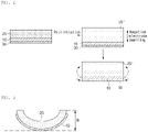
- In manufacturing the single-sided negative electrode, if the above-described pre-lithiation process is performed (specifically, from the moment when a preliminary negative electrode
active material layer 20 formed on acurrent collector 10 and a lithium metal (not shown) are bonded), strong stress is generated in the negative electrode active material layer 20' of the single-sided negative electrode due to the rapid volume expansion of a negative electrode active material into which lithium is inserted. Accordingly, the deformation in which both ends of the single-sided negative electrode are rolled toward an upper portion of the negative electrode active material layer 20' occurs (seeFIG. 1 ), and thus, the single-sided negative electrode may not be seamlessly bonded in the electrode assembly. In addition, the distance between the single-sided negative electrode and a positive electrode increases in the battery, so that resistance of the battery increases and side reactions occur intensively, causing the deterioration in the performance of the battery, and the energy density of the battery is reduced. - Therefore, there is a demand for a new technology capable of minimizing the deformation of a pre-lithiated negative electrode.
- An aspect of the present invention provides a negative electrode, a method for manufacturing the negative electrode, and a secondary battery including the negative electrode, wherein the deformation of a pre-lithiated negative electrode is minimized, thereby reducing the defective rate of the integration of a negative electrode/a separator/a positive electrode during an electrode assembly assembling process and improving the energy density, lifespan, and durability of a battery, and reducing side reactions.
- According to an aspect of the present invention, there is provided a method for manufacturing of a negative electrode, the method including forming a polymer layer on the rear surface of a current collector, forming a preliminary negative electrode active material layer on the front surface of the current collector, and forming a pre-lithiation layer including lithium on the preliminary negative electrode active material layer, wherein the polymer layer includes a copolymer having a first unit represented by Formula 1 below, and at least one of a second unit represented by Formula 2 below and a third unit represented by Formula 3 below.


- In Formula 3 above, R is each independently H or CH2CO2H.
- According to another aspect of the present invention, there is provided a negative electrode including a current collector, a negative electrode active material layer formed on the front surface of the current collector, and a polymer layer formed on the rear surface of the current collector, wherein the polymer layer includes a copolymer having a first unit represented by Formula 1 below, and at least one of a second unit represented by Formula 2 below and a third unit represented by Formula 3 below.


- In Formula 3 above, R is each independently H or CH2CO2H.
- According to yet another aspect of the present invention, there is provided a secondary battery including the negative electrode.
- According to the present invention, the deformation of a pre-lithiated negative electrode may be minimized through a polymer layer including a specific copolymer. Therefore, the defective rate of the local integration of a negative electrode/a separator/a positive electrode in an electrode assembly may be reduced, the energy density, lifespan, and durability of a battery may be improved, and local side reactions in the battery may be reduced.
-
-
FIG. 1 is a schematic diagram showing a method for manufacturing a typical pre-lithiated negative electrode; -
FIG. 2 is a schematic diagram showing a method for manufacturing a pre-lithiated negative electrode of the present invention; and -
FIG. 3 is a schematic diagram for explaining the measurement method of Experimental Example 1 of the present specification. - Hereinafter, the present invention will be described in more detail to facilitate understanding of the present invention.
- It will be understood that words or terms used in the specification and claims shall not be interpreted as having the meaning defined in commonly used dictionaries. It will be further understood that the words or terms should be interpreted as having a meaning that is consistent with their meaning in the context of the relevant art and the technical idea of the invention, based on the principle that an inventor may properly define the meaning of the words or terms to best explain the invention.
- The terminology used herein is for the purpose of describing particular exemplary embodiments only and is not intended to be limiting of the present invention. The terms of a singular form may include plural forms unless the context clearly indicates otherwise.
- It will be further understood that the terms "include," "comprise," or "have" when used in this specification, specify the presence of stated features, numbers, steps, elements, or combinations thereof, but do not preclude the presence or addition of one or more other features, numbers, steps, elements, or combinations thereof.
- In the formulas herein, "*" denotes a binding site.
- A method for manufacturing of a negative electrode according to an embodiment of the present invention includes forming a polymer layer on the rear surface(back surface) of a current collector S1, forming a preliminary negative electrode active material layer on the front surface(front surface) of the current collector S2, and forming a pre-lithiation layer including lithium on the preliminary negative electrode active material layer S3, wherein the polymer layer may include a copolymer having a first unit represented by Formula 1 below, and at least one of a second unit represented by Formula 2 below and a third unit represented by Formula 3 below.


- In Formula 3 above, R is each independently H or CH2CO2H.
- The current collector is not particularly limited as long as it has conductivity without causing a chemical change in a battery. For example, stainless steel, aluminum, nickel, titanium, fired carbon, or aluminum or stainless steel that is surface-treated with one of carbon, nickel, titanium, silver, and the like may be used. Also, the current collector may typically have a thickness of 3 µm to 500 µm, specifically 5 µm to 30 µm, and more preferably 6 µm to 15 µm. When the above range is satisfied, the energy density of the battery may be maintained at an appropriate level, and it is advantageous in terms of minimizing the deformation of the current collector due to pre-lithiation treatment by a polymer layer to be described later. Microscopic irregularities may be formed on the surface of the current collector to improve the adhesion of an active material. For example, the current collector may be used in various forms such as a film, a sheet, a foil, a net, a porous body, a foam, and a non-woven body.
- The polymer layer may be disposed on the rear surface of the current collector.
- The polymer layer may include a copolymer, and specifically, may be composed of a copolymer.
- The copolymer may include a first unit, and at least one of a second unit and a third unit. Specifically, the copolymer may be composed of at least one of the first unit, the second unit, and the third unit.
- The first unit may be a unit represented by Formula 1 below.


- The copolymer includes the first unit of Formula 1 above, and thus, the electrochemical reactivity of the copolymer is reduced, so that the initial charge/discharge efficiency of the battery may be improved. In addition, the lithium reduction consumption in the negative electrode may be reduced by the first unit of Formula 1 above.
- The first unit may be included in an amount of 10 mol% to 90 mol%, specifically 20 mol% to 80 mol%, more specifically 30 mol% to 60 mol% in the copolymer. When the above range is satisfied, the electrochemical reactivity of the copolymer is effectively reduced, and at the same time, a three-dimensional network structure may be formed at a desirable level by the polymerization with the second unit or the third unit, so that the deformation of the negative electrode may be reduced to a minimum.
- The second unit may be a unit of Formula 2 below, and the third unit may be a unit of Formula 3 below.


- In Formula 3 above, R is each independently H or CH2CO2H.
- The copolymer includes at least one of the second unit and the third unit, and thus, the brittleness of the copolymer may be improved.
- Typically, when lithium is inserted into the preliminary active material layer according to a pre-lithiation process, excessive stress is generated in the preliminary negative electrode active material layer due to the volume expansion of a negative electrode active material in the preliminary active material layer. Accordingly, the deformation in which both ends of the negative electrode are rolled toward an upper portion of the negative electrode active material layer (see
FIG. 1 ), and thus, the negative electrode may not be seamlessly bonded in an electrode assembly. In addition, the distance between the negative electrode and a positive electrode increases in the battery, so that resistance of the battery increases and side reactions occur intensively, causing the deterioration in the performance of the battery, and the energy density of the battery is reduced. - On the other hand, referring to
FIG. 2 , in an embodiment of the present invention, the deformation of the negative electrode active material layer 20' (in the form in which lithium is inserted into the preliminary negative electrodeactive material layer 20 by pre-lithiation) and thecurrent collector 10 may be suppressed by thepolymer layer 30. Specifically, since a copolymer included in the polymer layer includes at least one of the second unit and the third unit, the brittleness of the polymer layer is increased, allowing the force to relieve the stress causing the deformation of the negative electrode to act, so that the deformation of the negative electrode may be suppressed more effectively. - The content of the sum of the second unit represented by Formula 2 above and the third unit represented by Formula 3 above in the copolymer may be 10 mol% to 90 mol%, specifically 20 mol% to 80 mol%, more specifically 40 mol% to 70 mol%. When the above range is satisfied, a three-dimensional network structure may be formed at a desirable level by the polymerization of -OH or -COOH group in the second unit or the third unit and -COOH group in the first unit, so that the deformation of the negative electrode may be suppressed more effectively.
- The ratio of the molar content of the first unit and the total sum of the molar content of the second unit and the third unit in the copolymer may be 1:9 to 9:1, specifically 1:4 to 4:1, more specifically 1:1.75 to 1.75:1. When the above range is satisfied, the deformation of the negative electrode may be suppressed more effectively.
- The weight average molecular weight of the copolymer may be 200,000 g/mol to 1,000,000 g/mol, specifically 200,000 g/mol to 750,000 g/mol, more specifically 300,000 g/mol to 600,000 g/mol. When the above range is satisfied, the brittleness of the polymer layer is sufficient, so that the deformation of the negative electrode may be effectively suppressed, and at the same time, coating of the polymer layer is facilitated and damage (e.g., cracks, etc.) to the polymer layer is prevented, so that the resistance of the battery may be reduced, and the output properties, lifespan properties, and durability thereof may be improved.
- The copolymer may be a random copolymer, and in this case, a three-dimensional network structure may be formed at a desirable level by the polymerization of -OH or -COOH group in the second unit or the third unit and -COOH group in the first unit, so that the brittleness of the polymer layer is increased to suppress the deformation of the negative electrode more effectively.
- The thickness of the polymer layer may be 0.1 pm to 10 µm, specifically 0.5 pm to 2 µm. When the above range is satisfied, the deformation of the negative electrode may be effectively suppressed due to high brittleness of the polymer layer while the energy density of the battery remains high.
- The polymer layer may be disposed on the rear surface of the current collector in the following manner, but the present invention is not limited thereto.
- The copolymer is introduced into a solvent and then stirred to prepare a copolymer solution. Thereafter, the copolymer solution is applied on the rear surface of a current collector by means of such as slot-die, gravure, and comma coater. Thereafter, the current collector on which the copolymer solution is applied is dried to form a polymer layer.
- The preliminary negative electrode active material layer may be disposed on the front surface of the current collector. In other words, the preliminary negative electrode active material layer and the polymer layer may be positioned having the current collector interposed therebetween.
- The preliminary negative electrode active material layer may include a negative electrode active material.
- As the negative electrode active material, a compound capable of reversible intercalation and deintercalation of lithium may be used. Specific examples thereof may include a carbon-based material such as hard carbon, soft carbon, artificial graphite, natural graphite, graphitized carbon fiber, and amorphous carbon; a metallic compound alloyable with lithium such as Si, Al, Sn, Pb, Zn, Bi, In, Mg, Ga, Cd, a Si alloy, a Sn alloy, and an Al alloy; a metal oxide which may be doped and undoped with lithium such as SiOx(0<x<2), SiO2, SnO2, a vanadium oxide, and a lithium vanadium oxide; or a composite including the metallic compound and a carbonaceous material such as an Si-C composite, or an Sn-C composite, and any one thereof or a mixture of two or more thereof may be used. Specifically, the negative electrode active material may be at least one selected from the group consisting of a carbonaceous material, SiOx(0≤x≤2), SnO2, an Si-C composite, and an Sn-C composite. Furthermore, low crystalline carbon, high crystalline carbon and the like may all be used as a carbon material. Representative examples of the low crystalline carbon may include soft carbon and hard carbon, and representative examples of the high crystalline carbon may include irregular, planar, flaky, spherical, or fibrous natural graphite or artificial graphite, Kish graphite, pyrolytic carbon, mesophase pitch-based carbon fiber, meso-carbon microbeads, mesophase pitches, and high-temperature sintered carbon such as petroleum or coal tar pitch derived cokes.
- More specifically, the negative electrode active material may include at least one of SiOx(0≤x<2) and a carbon-based material. Particularly, SiOx(0≤x<2) has an advantage of improving the capacity of a negative electrode, but the SiOx(0≤x<2) has a disadvantage of having a large irreversible capacity, thereby having a low initial efficiency. In this respect, when following the method for manufacturing a negative electrode according to the present invention, the irreversible capacity of a negative electrode may be reduced, so that initial efficiency may be maintained even when the SiOx(0≤x<2) is included in a negative electrode active material, and the capacity of the negative electrode may be improved.
- The preliminary negative electrode active material layer may further include a binder. The binder may include at least any one selected from the group consisting of a polyvinylidene fluoride-hexafluoropropylene copolymer (PVDF-co-HFP), polyvinylidenefluoride, polyacrylonitrile, polymethylmethacrylate, polyvinyl alcohol, carboxymethyl cellulose (CMC), starch, hydroxypropyl cellulose, regenerated cellulose, polyvinylpyrrolidone, polytetrafluoroethylene, polyethylene, polypropylene, an ethylene-propylene-diene monomer (EPDM), a sulfonated EPDM, styrene-butadiene rubber (SBR), fluorine rubber, poly acrylic acid, a material having the hydrogen thereof substituted with Li, Na, or Ca, and the like. In addition, the binder may include various copolymers thereof.
- The preliminary negative electrode active material layer may further include a conductive material. The conductive material is not particularly limited as long as it has conductivity without causing a chemical change in the battery. For example, graphite such as natural graphite or artificial graphite; a carbon-based material such as carbon black, acetylene black, Ketjen black, channel black, furnace black, lamp black, and thermal black; conductive fiber such as carbon fiber and metal fiber; a conductive tube such as a carbon nanotube; fluorocarbon powder; metal powder such as aluminum powder, and nickel powder; a conductive whisker such as zinc oxide and potassium titanate; a conductive metal oxide such as titanium oxide; a conductive material such as a polyphenylene derivative, and the like may be used.
- The loading amount of the preliminary negative electrode active material layer may be 0.006 g/cm2 to 0.03 g/cm2, specifically 0.008 g/cm2 to 0.02 g/cm2. When the above range is satisfied, the energy density of the battery may be maintained high, and the coating of the preliminary negative electrode active material layer may be facilitated even with the use of a thin current collector.
- The thickness of the preliminary negative electrode active material layer may be 50 pm to 300 µm, specifically 100 µm to 180 µm. When the above range is satisfied, the energy density of the battery may be maintained high, and the coating of the preliminary negative electrode active material layer may be facilitated even with the use of a thin current collector.
- The preliminary negative electrode active material layer may be formed through a commonly known method. For example, a negative electrode slurry including the negative electrode active material, the binder, and the conductive material may be applied on the front surface of the current collector and then dried to form the preliminary negative electrode active material layer.
- The pre-lithiation layer may be formed on(the front surface of) the preliminary active material layer. The pre-lithiation layer and the current collector may be disposed having the preliminary active material layer interposed therebetween.
- The pre-lithiation layer serves to perform pre-lithiation by supplying lithium ions to the preliminary active material layer. Therefore, when pre-lithiation is finally performed, the pre-lithiation layer may disappear, or only a portion of lithium included in the pre-lithiation layer may remain on the preliminary active material layer.
- The pre-lithiation layer may include lithium, and specifically, the pre-lithiation layer may be composed of lithium.
- The thickness of the pre-lithiation layer may be 0.1 µm to 20 µm, specifically 1 µm to 10 µm. When the above range is satisfied, the effect of improving the energy of a battery by the pre-lithiation is pronounced, and the risk of lithium precipitation may be minimized.
- The ratio of the thickness of the polymer layer to the thickness of the pre-lithiation layer may be 1:200 to 100:1, specifically 1:100 to 20:1, more specifically 1:20 to 50:1. When the above range is satisfied, stress generated in the negative electrode during pre-lithiation may be effectively relieved, so that the deformation of the negative electrode may be reduced to a minimum.
- Although not necessarily limited thereto, the pre-lithiation layer may be formed on the preliminary negative electrode active material layer in the following manner.
- For example, the pre-lithiation layer may be formed on the preliminary negative electrode active material layer by forming a lithium layer on a release film such as PET by a vaporization method and the like, and then bonding the lithium layer and the preliminary negative electrode active material layer to each other, followed by removing the release film.
- A negative electrode according to another embodiment of the present invention may include a current collector, a negative electrode active material layer formed on the front surface of the current collector, and a polymer layer formed on the rear surface of the current collector, wherein the polymer layer includes a copolymer having a first unit represented by Formula 1 below, and at least one of a second unit represented by Formula 2 below and a third unit represented by Formula 3 below.


- In Formula 3 above, R is each independently H or CH2CO2H.
- The current collector, the polymer layer, and the copolymer are the same as the current collector, the polymer layer, and the copolymer of the embodiment described above, and thus, descriptions thereof will be omitted.
- The negative electrode active material layer means a negative electrode active material layer in which lithium ions supplied from the pre-lithiation layer of the above-described embodiment are inserted into the preliminary negative electrode active material layer of the above-described embodiment.
- The negative electrode may further include lithium disposed on the negative electrode active material layer. As described above, since lithium of the pre-lithiation layer of the above-described embodiment is inserted into the preliminary negative electrode active material layer, the pre-lithiation layer may disappear, or only a portion of the lithium of the pre-lithiation layer may remain on the negative electrode active material layer. At this time, the lithium remaining in part corresponds to the above-described lithium disposed on the negative electrode active material layer.
- A secondary battery according to yet another embodiment of the present invention may include a negative electrode. Specifically, the secondary battery may include an electrode assembly and an electrolyte, and the electrode assembly may include the negative electrode, a positive electrode, and a separator.
- The negative electrode is the negative electrode described above, and thus, the description thereof will be omitted.
- The positive electrode may include a positive electrode current collector and a positive electrode active material layer formed on the positive electrode current collector and including a positive electrode active material.
- In the positive electrode, the positive electrode current collector is not particularly limited as long as it has conductivity without causing a chemical change in the battery. For example, stainless steel, aluminum, nickel, titanium, fired carbon, or aluminum or stainless steel that is surface-treated with one of carbon, nickel, titanium, silver, and the like may be used. Also, the positive electrode current collector may typically have a thickness of 3 µm to 500 µm, and microscopic irregularities may be prepared on the surface of the positive electrode current collector to improve the adhesion of the positive electrode active material. For example, the current collector may be used in various forms such as a film, a sheet, a foil, a net, a porous body, a foam, and a non-woven body.
- The positive electrode active material may be a positive electrode active material commonly used in the art. Specifically, the positive electrode active material may be a layered compound such as lithium cobalt oxide (LiCoO2) and lithium nickel oxide (LiNiO2), or a compound substituted with one or more transition metals; a lithium iron oxide such as LiFe3O4; a lithium manganese oxide such as a formula Li1+c1Mn2-c1O4 (0≤c1≤0.33), LiMnO3, LiMn2O3, and LiMnO2; lithium copper oxide (Li2CuO2); a vanadium oxide such as LiV3O8, V2O5, and Cu2V2O7; a Ni-site type lithium nickel oxide represented by the formula LiNi1-c2Mc2O2 (wherein M is any one of Co, Mn, Al, Cu, Fe, Mg, B or Ga, and 0.01≤c2≤0.3); a lithium manganese composite oxide represented by the formula LiMn2-c3Mc3O2 (wherein, M is any one of Co, Ni, Fe, Cr, Zn, or Ta, and 0.01≤c3≤0.1), or by the formula (wherein, M is any one of Fe, Co, Ni, Cu, or Zn); LiMn2O4 having a part of Li in the formula substituted with an alkaline earth metal ion, and the like, but is not limited thereto. The positive electrode may be a Li-metal.
- The positive electrode active material layer may include a positive electrode conductive material and a positive electrode binder, together with the positive electrode active material described above.
- At this time, the positive electrode conductive material is used to impart conductivity to an electrode, and any positive electrode conductive material may be used without particular limitation as long as it has electronic conductivity without causing a chemical change in a battery to be constituted. Specific examples thereof may include graphite such as natural graphite or artificial graphite; a carbon-based material such as carbon black, acetylene black, Ketjen black, channel black, furnace black, lamp black, thermal black, and carbon fiber; metal powder or metal fiber of such as copper, nickel, aluminum, and silver; a conductive whisker such as a zinc oxide whisker and a potassium titanate whisker; a conductive metal oxide such as a titanium oxide; or a conductive polymer such as a polyphenylene derivative, and any one thereof or a mixture of two or more thereof may be used.
- In addition, the positive electrode binder serves to improve the bonding between positive electrode active material particles and the adhesion between the positive electrode active material and the positive electrode current collector. Specific examples thereof may include polyvinylidene fluoride (PVDF), a polyvinylidene fluoride-hexafluoropropylene copolymer (PVDF-co-HFP), polyvinyl alcohol, polyacrylonitrile, carboxymethyl cellulose (CMC), starch, hydroxypropyl cellulose, regenerated cellulose, polyvinylpyrrolidone, polytetrafluoroethylene, polyethylene, polypropylene, an ethylene-propylene-diene monomer (EPDM), a sulfonated EPDM, styrene-butadiene rubber (SBR), fluorine rubber, or various copolymers thereof, and any one thereof or a mixture of two or more thereof may be used.
- The separator is to separate the negative electrode and the positive electrode and to provide a movement path for lithium ions. Any separator may be used without particular limitation as long as it is a separator commonly used in a secondary battery. Particularly, a separator having excellent moisture-retention of an electrolyte as well as low resistance to ion movement in the electrolyte is preferable. Specifically, a porous polymer film, for example, a porous polymer film manufactured using a polyolefin-based polymer such as an ethylene homopolymer, a propylene homopolymer, an ethylene/butene copolymer, an ethylene/hexene copolymer, and an ethylene/methacrylate copolymer, or a laminated structure having two or more layers thereof may be used. Also, a typical porous non-woven fabric, for example, a non-woven fabric formed of glass fiber having a high melting point, polyethylene terephthalate fiber, or the like may be used. Also, a coated separator including a ceramic component or a polymer material may be used to secure heat resistance or mechanical strength, and may be selectively used in a single-layered or a multi-layered structure.
- The electrode assembly includes a structure in which the negative electrode and the positive electrode are spaced apart from each other having the separator interposed therebetween. At this time, the negative electrode of the electrode assembly may include a single-sided negative electrode in which a negative electrode active material layer is disposed on only one surface of a current collector. The single-sided negative electrode may be used as a negative electrode closest to the outermost periphery of the electrode assembly, and the single-sided negative electrode corresponds to the negative electrode of the above-described embodiment.
- The electrolyte may be an organic liquid electrolyte, an inorganic liquid electrolyte, a solid polymer electrolyte, a gel-type polymer electrolyte, a solid inorganic electrolyte, a molten-type inorganic electrolyte, and the like, which may be used in the preparation of a lithium secondary battery, but is not limited thereto.
- Specifically, the electrolyte may include a non-aqueous organic solvent and a lithium salt.
- As the non-aqueous organic solvent, for example, an aprotic organic solvent, such as N-methyl-2-pyrrolidone, propylene carbonate, ethylene carbonate, butylene carbonate, dimethyl carbonate, diethyl carbonate, γ-butyrolactone, 1,2-dimethoxy ethane, tetrahydrofuran, 2-methyl tetrahydrofuran, dimethyl sulfoxide, 1,3-dioxolane, formamide, diemthylformamide, dioxolane, acetonitrile, nitromethane, methyl formate, methyl acetate, phosphate triester, trimethoxy methane, a dioxolane derivative, sulfolane, methyl sulfolane, 1,3-dimethyl-2-imidazolidinone, a propylene carbonate derivative, a tetrahydrofuran derivative, ether, methyl propionate, and ethyl propionate may be used.
- In particular, among the carbonate-based organic solvents, a cyclic carbonate such as ethylene carbonate and propylene carbonate may preferably be used since it is an organic solvent of high viscosity and has high dielectric constant to dissociate a lithium salt well. Such a cyclic carbonate may be more preferably used since when it is mixed with a linear carbonate of low viscosity and low dielectric constant such as dimethyl carbonate and diethyl carbonate in an appropriate ratio, an electrolyte having a high electric conductivity is prepared.
- As the metal salt, a lithium salt may be used. The lithium salt is a material which is easily dissolved in the non-aqueous electrolyte solution. For example, as an anion of the lithium salt, one or more selected from the group consisting of F-, Cl-, I-, NO3 -, N(CN)2 -, BF4 -, ClO4 -, PF6 -, (CF3)2PF4 -, (CF3)3PF3 -, (CF3)4PF2 -, (CF3)5PF-, (CF3)6P-, CF3SO3 -, CF3CF2SO3 -, (CF3SO2)2N-, (FSO2)2N-, CF3CF2(CF3)2CO-, (CF3SO2)2CH-, (SF5)3C-, (CF3SO2)3C-, CF3(CF2)7SO3 -, CF3CO2 -,CH3CO2 -, SCN-, and (CF3CF2SO2)2N- may be used.
- In the electrolyte, in order to improve the lifespan properties of a battery, to suppress the decrease in battery capacity, and to improve the discharge capacity of the battery, one or more additives, for example, a halo-alkylene carbonate-based compound such as difluoroethylene carbonate, pyridine, triethylphosphite, triethanolamine, cyclic ether, ethylenediamine, n-glyme, hexaphosphoric triamide, a nitrobenzene derivative, sulfur, a quinone imine dye, N-substituted oxazolidinone, N,N-substituted imidazolidine, ethylene glycol dialkyl ether, an ammonium salt, pyrrole, 2-methoxy ethanol, or aluminum trichloride, and the like may be further included other than the above electrolyte components.
- According to yet another embodiment of the present invention, a battery module including the secondary battery as a unit cell, and a battery pack including the same are provided. The battery module and the battery pack include the secondary battery which has high capacity, high rate properties, and cycle properties, and thus, may be used as a power source of a medium-and-large sized device selected from the group consisting of an electric car, a hybrid electric vehicle, a plug-in hybrid electric vehicle, and a power storage system.
- Hereinafter, preferred embodiments of the present invention will be described in detail to facilitate understanding of the present invention. However, the embodiments are merely illustrative of the present invention, and thus, it will be apparent to those skilled in the art that various modifications and variations can be made without departing from the scope and spirit of the present invention as disclosed in the accompanying claims. It is obvious that such variations and modifications fall within the scope of the appended claims.
- A random copolymer(weight average molecular weight: 250,000 g/mol) composed of a first unit(60 mol%) of Formula 1 below and a second unit(40 mol%) of Formula 2 below was introduced to acetone, which is a solvent, to prepare a copolymer solution having a solid content of 7 wt%.


- Thereafter, the solution was applied on a copper current collector having a thickness of 8 µm and dried at 60°C to form a polymer layer on the rear surface of the current collector.
- 92 wt% of a negative electrode active material (graphite:SiO=7:3 weight ratio), 3 wt% of Denka black (conductive material), 3.5 wt% of SRB (binder), and 1.5 wt% of CMC (thickener) were added to water to prepare a negative electrode slurry.
- The negative electrode slurry was applied on the front surface of the current collector (a surface positioned in the opposite direction to a surface of the current collector on which the polymer layer is formed), dried, and then roll-pressed to form a preliminary negative electrode active material layer. The loading amount of the preliminary negative electrode active material layer was 0.009 g/cm2, the thickness thereof was 149 µm, and the porosity thereof was 26%.
- A lithium layer (thickness: 5 µm) composed of lithium was vapor-deposited on a PET release film to prepare a film for pre-lithiation having a thickness of 5 µm. Thereafter, the film for pre-lithiation and the negative electrode were adhered to each other to bond the lithium layer to the preliminary negative electrode active material layer. Thereafter, while maintaining the roll-pressing roll gap to correspond to 90% of the total thickness of the film for pre-lithiation and the negative electrode. roll-pressing was performed. Thereafter, the release film was removed to form a pre-lithiation layer on the preliminary negative electrode active material layer and perform pre-lithiation.
- Finally, the thickness of the polymer layer in the negative electrode was 0.5 µm.
- A negative electrode was manufactured in the same manner as in Example 1 except that while a copolymer composed of a first unit of Formula 1 above and a second unit of Formula 2 above was used as in Example 1, but the weight average molecular weight of the copolymer was 500,000 g/mol.
- A negative electrode was manufactured in the same manner as in Example 1 except that instead of the copolymer of Example 1, a copolymer(weight average molecular weight: 250,000 g/mol) composed of a first unit(60 mol%) of Formula 1 above and a third unit(40 mol%) of Formula 3 below was used.

- A negative electrode was manufactured in the same manner as in Example 1 except that instead of the copolymer of Example 1, polyethylene (PE)(weight average molecular weight: 250,000 g/mol) was used.
- A negative electrode was manufactured in the same manner as in Example 1 except that instead of the copolymer of Example 1, polyacrylic acid (PAA)(weight average molecular weight: 250,000 g/mol) was used.
- A negative electrode was manufactured in the same manner as in Example 1 except that a polymer layer was not formed.
- The negative electrode (15cm×15cm) of each of Examples 1 to 3 and Comparative Examples 1 to 3 was left to stand for 2 hours at 25°C, and then the degree of deformation of the negative electrode was evaluated.
- After being left to stand, the negative electrode was deformed as shown in
FIG. 3 (polymer layer not shown). Specifically, the end of the negative electrode was rolled toward an upper portion of the negative electrode active material layer, so that the cross-section of the negative electrode became to have a curve form having a curvature. At this time, a distance H(in direction perpendicular to the ground) between the ground and the end(of the four vertexes of the negative electrode, a vertex that is spaced farthest from the ground) of the negative electrode was measured and shown in Table 1. The H was measured with a steel ruler.[Table 1] H (mm) Example 1 9 Example 2 5 Example 3 10 Comparative Example 1 16 Comparative Example 2 12 Comparative Example 3 Two edges facing the negative electrode meet each other on the negative electrode active material layer, so that the negative electrode becomes to have a cylinder form. - Referring to Table 1 above, the negative electrode of each of Examples 1 to 3 has a smaller degree of deformation compared to the negative electrode of each of Comparative Examples. Specifically, in the case of Comparative Example 3, it was confirmed that the negative electrode was bent the most, making the H measurement meaningless. In the case of Comparative Examples 1 and 2, the brittleness of the polymer layer was poor, so that the deformation of the negative electrode was not effectively controlled.
Claims (14)
- A negative electrode comprising:a current collector;a negative electrode active material layer formed on the front surface of the current collector; anda polymer layer formed on the rear surface of the current collector, wherein the polymer layer includes a copolymer having a first unit represented by Formula 1 below, and at least one of a second unit represented by Formula 2 below and a third unit represented by Formula 3 below:


 wherein, in Formula 3 above, R is each independently H or CH2CO2H.
 - The negative electrode of claim 1, wherein the weight average molecular weight of the copolymer is 200,000 g/mol to 1,000,000 g/mol.
- The negative electrode of claim 1, wherein the weight average molecular weight of the copolymer is 300,000 g/mol to 600,000 g/mol.
- The negative electrode of claim 1, wherein the content of the sum of the second unit represented by Formula 2 above and the third unit represented by Formula 3 above in the copolymer is 10 mol% to 90 mol%.
- The negative electrode of claim 1, wherein the thickness of the polymer layer is 0.1 µm to 10 µm.
- The negative electrode of claim 1, further comprising lithium disposed on the negative electrode active material layer.
- A method for manufacturing a negative electrode, the method comprising:forming a polymer layer on the rear surface of a current collector;forming a preliminary negative electrode active material layer on the front surface of the current collector; andforming a pre-lithiation layer including lithium on the preliminary negative electrode active material layer, wherein the polymer layer includes a copolymer having a first unit represented by Formula 1 below, and at least one of a second unit represented by Formula 2 below and a third unit represented by Formula 3 below:


 wherein, in Formula 3 above, R is each independently H or CH2CO2H.
 - The method of claim 7, wherein the weight average molecular weight of the copolymer is 200,000 g/mol to 1,000,000 g/mol.
- The method of claim 7, wherein the weight average molecular weight of the copolymer is 300,000 g/mol to 600,000 g/mol.
- The method of claim 7, wherein the content of the sum of the second unit represented by Formula 2 above and the third unit represented by Formula 3 above in the copolymer is 10 mol% to 90 mol%.
- The method of claim 7, wherein the thickness of the polymer layer is 0.1 µm to 10 µm.
- The method of claim 7, wherein the thickness of the pre-lithiation layer is 0.1 µm to 20 µm.
- The method of claim 7, wherein the ratio of the thickness of the polymer layer to the thickness of the pre-lithiation layer is 1:200 to 100:1.
- A secondary battery comprising the negative electrode of claim 1.
Applications Claiming Priority (2)
| Application Number | Priority Date | Filing Date | Title |
|---|---|---|---|
| KR1020190142958A KR20210056169A (en) | 2019-11-08 | 2019-11-08 | Negative electrode, method for preparing the negative electrode, and secondary battery including the negative electrode |
| PCT/KR2020/015449 WO2021091278A1 (en) | 2019-11-08 | 2020-11-06 | Negative electrode, negative electrode production method and secondary battery comprising negative electrode |
Publications (2)
| Publication Number | Publication Date |
|---|---|
| EP4030501A1 true EP4030501A1 (en) | 2022-07-20 |
| EP4030501A4 EP4030501A4 (en) | 2022-12-21 |
Family
ID=75848992
Family Applications (1)
| Application Number | Title | Priority Date | Filing Date |
|---|---|---|---|
| EP20885609.6A Pending EP4030501A4 (en) | 2019-11-08 | 2020-11-06 | Negative electrode, negative electrode production method and secondary battery comprising negative electrode |
Country Status (5)
| Country | Link |
|---|---|
| US (1) | US20240030457A1 (en) |
| EP (1) | EP4030501A4 (en) |
| KR (1) | KR20210056169A (en) |
| CN (1) | CN114514641B (en) |
| WO (1) | WO2021091278A1 (en) |
Family Cites Families (13)
| Publication number | Priority date | Publication date | Assignee | Title |
|---|---|---|---|---|
| DE3838329A1 (en) * | 1987-11-11 | 1989-05-24 | Ricoh Kk | Negative electrode for a secondary battery |
| JP4053657B2 (en) * | 1997-05-30 | 2008-02-27 | 三菱化学株式会社 | Lithium secondary battery and manufacturing method thereof |
| JP2011028883A (en) * | 2009-07-22 | 2011-02-10 | Panasonic Corp | Nonaqueous electrolyte secondary battery |
| CN105374571B (en) * | 2014-08-26 | 2018-01-23 | 万星光电子(东莞)有限公司 | Lithium-ion capacitor negative plate and preparation method thereof, winding type lithium ion capacitor |
| CN106128791B (en) * | 2016-06-29 | 2018-11-06 | 中航锂电(洛阳)有限公司 | A kind of negative plate, preparation method and the lithium-ion capacitor using the negative plate |
| KR101984722B1 (en) * | 2016-07-21 | 2019-05-31 | 주식회사 엘지화학 | Lithium Secondary Battery containing Cathod Active Material Synthesizing Lithium Cobalt Oxide, Manufacturing Method Thereof |
| JP2018181705A (en) * | 2017-04-18 | 2018-11-15 | 株式会社村田製作所 | Secondary battery and manufacturing method thereof |
| KR102270864B1 (en) * | 2017-04-19 | 2021-07-01 | 주식회사 엘지에너지솔루션 | Negative electrode for lithium secondary battery, lithium secondary battery comprising the same, and preparing method thereof |
| CN107134561B (en) * | 2017-05-05 | 2019-12-03 | 杭州金色能源科技有限公司 | Battery pole piece and the method for preventing battery pole piece from crimping |
| KR102261504B1 (en) * | 2017-08-10 | 2021-06-07 | 주식회사 엘지에너지솔루션 | Pre-lithiation Method of Anode Electrodes for secondary battery |
| US20200014031A1 (en) * | 2017-10-25 | 2020-01-09 | Lg Chem, Ltd. | One-sided electrode with reduced twisting for a secondary battery, and method for producing same |
| JP2019169360A (en) * | 2018-03-23 | 2019-10-03 | Tdk株式会社 | Positive electrode active material layer and lithium ion secondary battery |
| KR102386322B1 (en) * | 2018-04-17 | 2022-04-14 | 주식회사 엘지에너지솔루션 | Negative electrode for lithium secondary battery, preparing method thereof, and lithium secondary battery comprising the same |
-
2019
- 2019-11-08 KR KR1020190142958A patent/KR20210056169A/en unknown
-
2020
- 2020-11-06 US US17/768,690 patent/US20240030457A1/en active Pending
- 2020-11-06 EP EP20885609.6A patent/EP4030501A4/en active Pending
- 2020-11-06 WO PCT/KR2020/015449 patent/WO2021091278A1/en active Application Filing
- 2020-11-06 CN CN202080069843.0A patent/CN114514641B/en active Active
Also Published As
| Publication number | Publication date |
|---|---|
| KR20210056169A (en) | 2021-05-18 |
| CN114514641A (en) | 2022-05-17 |
| CN114514641B (en) | 2023-12-05 |
| EP4030501A4 (en) | 2022-12-21 |
| US20240030457A1 (en) | 2024-01-25 |
| WO2021091278A1 (en) | 2021-05-14 |
Similar Documents
| Publication | Publication Date | Title |
|---|---|---|
| EP3731312B1 (en) | Method for manufacturing negative electrode | |
| US10622625B2 (en) | Positive electrode and secondary battery including the same | |
| US20230282811A1 (en) | Negative electrode active material, negative electrode including the negative electrode active material, and secondary battery including the negative electrode | |
| KR20200073801A (en) | Negative electrode and lithium secondary battery comprising the negative electrode | |
| KR102158680B1 (en) | Method for preparing positive electrode for secondary battery | |
| KR20200088237A (en) | Negative electrode and lithium secondary battery comprising the negative electrode | |
| EP3534436B1 (en) | Negative electrode, secondary battery including same negative electrode, and method for manufacturing same negative electrode | |
| KR20210058172A (en) | Negative electrode and secondary battery comprising the negative electrode | |
| US20220115667A1 (en) | Negative electrode and secondary battery including the negative electrode | |
| KR20210067735A (en) | Positive Electrode for Secondary Battery Comprising Flake Graphite And Secondary Battery Comprising the Same | |
| KR102492760B1 (en) | Method for preparing negative electrode active material | |
| KR102104490B1 (en) | Method for charging of secondary battery | |
| EP4030501A1 (en) | Negative electrode, negative electrode production method and secondary battery comprising negative electrode | |
| KR20220006006A (en) | Negative electrode and secondary battery comprising the negative electorde | |
| US20220359855A1 (en) | Method of preparing negative electrode | |
| CN113646946A (en) | Secondary battery | |
| KR102601530B1 (en) | Negative electrode for lithium secondary battery, lithium secondary battery comprising negative electrode, and method for preparing negative electrode for lithium secondary battery | |
| KR102288128B1 (en) | Negative electrode active material, negative electrode comprising the negative electrode active material, lithium secondarty battery comprising the negative electrode, and method for prepareing the negative electrode active material | |
| CN114586218B (en) | Novel method for manufacturing secondary battery | |
| KR20240000397A (en) | Negative electrode for lithium secondary battery, method for preparing negative electrode for lithium secondary battery, and lithium secondary battery comprising negative electrode | |
| KR20240000399A (en) | Negative electrode for lithium secondary battery, method for preparing negative electrode for lithium secondary battery, and lithium secondary battery comprising negative electrode | |
| US20220352499A1 (en) | Negative electrode and secondary battery including same | |
| US20220238869A1 (en) | Negative electrode and secondary battery including the negative electrode | |
| KR20240000396A (en) | Negative electrode for lithium secondary battery and lithium secondary battery comprising negative electrode | |
| KR20240023003A (en) | Positive electrode, method for preparing the same, and secondary battery comprising the positive electrode |
Legal Events
| Date | Code | Title | Description |
|---|---|---|---|
| STAA | Information on the status of an ep patent application or granted ep patent |
Free format text: STATUS: THE INTERNATIONAL PUBLICATION HAS BEEN MADE |
|
| PUAI | Public reference made under article 153(3) epc to a published international application that has entered the european phase |
Free format text: ORIGINAL CODE: 0009012 |
|
| STAA | Information on the status of an ep patent application or granted ep patent |
Free format text: STATUS: REQUEST FOR EXAMINATION WAS MADE |
|
| 17P | Request for examination filed |
Effective date: 20220411 |
|
| AK | Designated contracting states |
Kind code of ref document: A1 Designated state(s): AL AT BE BG CH CY CZ DE DK EE ES FI FR GB GR HR HU IE IS IT LI LT LU LV MC MK MT NL NO PL PT RO RS SE SI SK SM TR |
|
| A4 | Supplementary search report drawn up and despatched |
Effective date: 20221121 |
|
| RIC1 | Information provided on ipc code assigned before grant |
Ipc: H01M 4/1395 20100101ALI20221115BHEP Ipc: H01M 4/1393 20100101ALI20221115BHEP Ipc: H01M 4/134 20100101ALI20221115BHEP Ipc: H01M 4/133 20100101ALI20221115BHEP Ipc: H01M 4/02 20060101ALI20221115BHEP Ipc: H01M 4/587 20100101ALI20221115BHEP Ipc: H01M 4/48 20100101ALI20221115BHEP Ipc: H01M 4/36 20060101ALI20221115BHEP Ipc: H01M 10/052 20100101ALI20221115BHEP Ipc: H01M 4/04 20060101ALI20221115BHEP Ipc: H01M 4/139 20100101ALI20221115BHEP Ipc: H01M 4/66 20060101ALI20221115BHEP Ipc: H01M 4/62 20060101ALI20221115BHEP Ipc: H01M 4/13 20100101AFI20221115BHEP |
|
| DAV | Request for validation of the european patent (deleted) | ||
| DAX | Request for extension of the european patent (deleted) |