EP4030337B1 - Optical sensor and method for detecting codes - Google Patents
Optical sensor and method for detecting codes Download PDFInfo
- Publication number
- EP4030337B1 EP4030337B1 EP21151994.7A EP21151994A EP4030337B1 EP 4030337 B1 EP4030337 B1 EP 4030337B1 EP 21151994 A EP21151994 A EP 21151994A EP 4030337 B1 EP4030337 B1 EP 4030337B1
- Authority
- EP
- European Patent Office
- Prior art keywords
- received signals
- optical sensor
- codes
- designed
- receiver
- Prior art date
- Legal status (The legal status is an assumption and is not a legal conclusion. Google has not performed a legal analysis and makes no representation as to the accuracy of the status listed.)
- Active
Links
- 230000003287 optical effect Effects 0.000 title claims description 43
- 238000000034 method Methods 0.000 title claims description 6
- 238000011156 evaluation Methods 0.000 claims description 35
- 230000001537 neural effect Effects 0.000 claims description 23
- 238000013528 artificial neural network Methods 0.000 claims description 17
- 238000003708 edge detection Methods 0.000 claims description 12
- 238000012549 training Methods 0.000 claims description 9
- 230000001629 suppression Effects 0.000 claims description 3
- 230000000926 neurological effect Effects 0.000 claims 1
- 238000001514 detection method Methods 0.000 description 9
- 230000007704 transition Effects 0.000 description 5
- 230000006835 compression Effects 0.000 description 2
- 238000007906 compression Methods 0.000 description 2
- 230000001419 dependent effect Effects 0.000 description 2
- 238000010586 diagram Methods 0.000 description 2
- 238000010801 machine learning Methods 0.000 description 2
- 230000005693 optoelectronics Effects 0.000 description 2
- 230000036961 partial effect Effects 0.000 description 2
- 230000006978 adaptation Effects 0.000 description 1
- 238000011161 development Methods 0.000 description 1
- 230000018109 developmental process Effects 0.000 description 1
- 238000005259 measurement Methods 0.000 description 1
- 238000012545 processing Methods 0.000 description 1
- 230000036962 time dependent Effects 0.000 description 1
- 238000011144 upstream manufacturing Methods 0.000 description 1
Images


Classifications
-
- G—PHYSICS
- G06—COMPUTING; CALCULATING OR COUNTING
- G06K—GRAPHICAL DATA READING; PRESENTATION OF DATA; RECORD CARRIERS; HANDLING RECORD CARRIERS
- G06K7/00—Methods or arrangements for sensing record carriers, e.g. for reading patterns
- G06K7/10—Methods or arrangements for sensing record carriers, e.g. for reading patterns by electromagnetic radiation, e.g. optical sensing; by corpuscular radiation
- G06K7/14—Methods or arrangements for sensing record carriers, e.g. for reading patterns by electromagnetic radiation, e.g. optical sensing; by corpuscular radiation using light without selection of wavelength, e.g. sensing reflected white light
- G06K7/1404—Methods for optical code recognition
- G06K7/146—Methods for optical code recognition the method including quality enhancement steps
- G06K7/1482—Methods for optical code recognition the method including quality enhancement steps using fuzzy logic or natural solvers, such as neural networks, genetic algorithms and simulated annealing
Definitions
- the invention relates to an optical sensor and a method for detecting codes.
- optical sensors designed as code readers are used in particular to detect barcodes.
- the optical sensors are typically designed as scanners or camera-based sensors.
- an optical sensor in the form of a scanner light beams emitted by a transmitter are periodically deflected within a detection area by means of a deflection unit and thereby guided over a barcode to be detected.
- the received signals thereby generated at the receiver of the optical sensor form an amplitude-modulated intensity signal, the amplitude modulation being designed in accordance with the contrast pattern of the barcode.
- an image sensor is provided as a receiver, with which an amplitude-modulated intensity signal of the barcode is also obtained.
- the code is typically captured in such a way that the received signals from the receiver are differentiated and then fed to an evaluation unit via an analog-digital converter, where the code is decoded based on the differentiated received signals sampled and digitized with the analog-digital converter. For this purpose, the edge positions of light-dark transitions present in the codes are determined based on the extreme points of the differentiated, sampled received signal.
- a major problem is that due to the very different reading situations that occur in the applications, the levels of the Receive signals obtained by scanning codes vary greatly. This results in the limited control range of the analogue-digital converter being exceeded, so that the signal at the output of the analogue-digital converter is limited. This limitation causes information from the differentiated received signals, in particular information about edge positions, which is essential for the detection of codes, to be lost. This in turn leads to incorrect detections when detecting the codes.
- the DE 101 37 093 A1 relates to a method for recognizing a code, in which the code is located and/or identified within an image environment. This step is carried out using a neural network.
- the invention further relates to a corresponding code reader.
- an optoelectronic code reader in particular a barcode reader, is specified with at least one light receiving element for generating image data from received light and with an evaluation unit in which a classifier is implemented which assigns code information to code areas of the image data, the classifier being designed for machine learning and by means of Supervised learning is trained using codes read from a classic decoder that works with methods without machine learning.
- DE 10 2004 059 604 A1 relates to an optoelectronic device for detecting marks having contrast patterns, with a transmitter emitting transmitted light beams, a receiver receiving received light beams, a deflection unit for periodically deflecting the transmitted light beams within a scanning area, and with an evaluation unit in which the received light beams are decoded by the contrast patterns for decoding the marks impressed amplitude modulations can be evaluated.
- the transmitter and the receiver also form a distance sensor element that works according to the phase measurement principle. To eliminate interference signal components during contrast pattern detection, the determined distance values and amplitude values of the received signals from the receiver are linked in the evaluation unit.
- the EP 0 419 226 A2 concerns a barcode reader with a signal processor.
- the signal processor has a differentiator and a filter unit
- the invention is based on the object of improving the error security in the detection of codes in an optical sensor of the type mentioned.
- the invention relates to an optical sensor for detecting codes, with a transmitter emitting light beams and a receiver receiving light beams, which are designed to scan codes, and with an evaluation unit which is used to determine code information of the codes in Dependence on received signals from the receiver is formed.
- the received signals from the receiver are fed to an evaluation circuit in which sampled received signals are generated from the received signals.
- a neural system is provided, the evaluation circuit having a differentiator in which the received signals are differentiated and an analog-digital converter downstream of it.
- the sampled received signals generated in the analog-digital converter are fed to the evaluation unit, with the neural system being part of the evaluation unit.
- the evaluation unit has a unit for edge detection, with the neural system at least partially recovering code information that was lost by limiting the levels of the received signals and thereby compensating for limitations in the levels of the sampled received signals.
- the invention further relates to a method for detecting codes.
- the basic idea of the invention is therefore to compensate for limitations present in the sampled received signals at the output of the evaluation circuit using a neural system.
- the limitation of the sampled received signals which is caused by the evaluation circuit, can at least partially be reversed. This means that information about scanned codes that were lost due to the limitation can be at least partially recovered. This can significantly increase the error security when detecting the codes.
- the evaluation circuit has a differentiator, in which the received signals are differentiated, and an analog-digital converter downstream of it.
- the evaluation unit has a unit for edge detection.
- edge positions of light-dark transitions of read codes are determined in the edge detection unit by determining the extreme points in the differentiated received signals.
- the received signals differentiated in the differentiator In order to supply the received signals differentiated in the differentiator to the evaluation unit and the edge detection unit integrated therein, they are sampled and digitized in the analog-digital converter. The sampled received signals present at the output of the analog-digital converter can then be read directly into the evaluation unit.
- the levels of the received signals vary greatly, so that these in the analog-digital converter limited control range, as a result of which information in the received signals about the read codes is lost.
- the neural system downstream of the analog-digital converter and upstream of the edge detection unit can at least partially recover the code information lost due to the limitation of the analog-digital converter, so that reliable decoding and thus detection of the code is guaranteed.
- the optical sensor according to the invention is advantageously designed as a scanner or as a camera sensor.
- the optical sensor is expediently designed to detect barcodes.
- the barcodes consist of a linear sequence of light and dark modules. To decode the barcodes, the edge positions of the light-dark transitions of these modules are recorded.
- the optical sensor is advantageously designed in such a way that codes can be detected within a reading range.
- optical sensor can be used to detect codes not only at a single reading distance but also over an extended reading range, which is generally achieved by suitable optical elements that are assigned to the transmitter and/or receiver of the optical sensor.
- the neural system can advantageously be designed as a neural network.
- a Training a number of sampled received signals and assigned target output signals are specified at the output of the neural system.
- Reception signals sampled during training and assigned target output signals for different reading situations are expediently specified.
- the parameters of the neural system are determined, and it is advantageous if the sampled received signals and target output signals used for this cover as many different reading situations as possible, so that a correspondingly broad and extensive adaptation of the neural network to the possible reading situations is ensured.
- the different reading situations can be different noise amplitudes, signal frequencies or even different ratios of the spot diameters of the light beams of the optical sensor in relation to module widths of codes to be read.
- the training carried out in this way makes it possible for the neural system to be trained to carry out noise suppression.
- the reading range of the optical sensor can be enlarged by means of the neural system.
- Figure 1 shows an exemplary embodiment of the optical sensor components of the optical sensor 1 according to the invention, which is designed as a code reader and specifically as a barcode reader.
- the optical sensor 1 has a transmitter 3 that emits light beams 2 and a receiver 4 that receives light beams 2.
- the transmitter 3 can be formed by a light-emitting diode or laser diode
- the receiver 4 can be formed by a photodiode.
- the light beams 2 are periodically deflected within a detection area via a deflection unit.
- the deflection unit consists of a motor-driven polygon mirror wheel 5.
- the polygon mirror wheel 5 can be rotated about an axis of rotation that runs perpendicular to the plane of the drawing.
- the light rays 2 are deflected at the facets 6 of the polygon mirror wheel 5.
- the light beams 2 are guided over a barcode 8 arranged on an object 7, which consists in a known manner of a sequence of light and dark line elements.
- the received signals from the receiver 4 obtained during the detection of the barcode 8 form an amplitude-modulated one Intensity signal, the contrast pattern of the barcode 8 being contained in the amplitude modulation of the intensity signal.
- Figure 2 shows a further example of the optical sensor components of the optical sensor 1 designed as a barcode reader.
- an image sensor for example a CMOS or CCD array
- a lighting unit for example a light-emitting diode arrangement
- a barcode 8 is detected on an object 7, like Figure 2 shows.
- the output signals of the receiving elements of the receiver 4 again deliver an amplitude-modulated intensity signal, the contrast pattern of the barcode 8 being encoded in the amplitude modulation.
- Figure 3 shows a block diagram of the optical sensor 1.
- Figure 3 are schematically the optical sensor components for detecting the barcode 8 on the object 7, as in the Figures 1 and 2 shown, shown as scanner front end 9.
- the time-dependent received signals z A ( t ) generated there are differentiated in a differentiator 10.
- the differentiated received signals ⁇ A ( t ) are fed to an analog-digital converter 11. There the differentiated received signals are sampled and digitized.
- the sampled received signals x(k) present at the output of the analog-digital converter 11 are fed to an evaluation unit in the form of a computer unit.
- the evaluation unit has a neural network 12 and an edge detection unit 13 downstream of it.
- the barcodes 8 have a sequence of light and dark modules.
- the evaluation for decoding the barcodes 8 is carried out in the edge detection unit 13 in such a way that the edge positions of the light-dark transitions of the barcodes 8, which are given by the extreme points of the differentiated received signals, are detected based on the differentiated received signals.
- the differentiated received signals Due to the limited control range of the analog-digital converter 11, depending on the level of the received signals, which are used in addition to the differentiated received signals in the evaluation unit for detecting the barcodes 8, the differentiated received signals are limited, as a result of which information about the barcodes 8 is lost.
- the limitation of sampled received signals read in by the analog-digital converter 11 is compensated for in the neural network 12.
- This compensation reverses limitations in the sampled received signals, so that lost edge information in the sampled received signals is recovered in the output signals y ( k ) of the neural network 12.
- the neural network 12 is trained, which is carried out before the optical sensor 1 is in operation.
- the largest possible number of sampled received signals and assigned target output signals is specified.
- received signals sampled during training and assigned target output signals are specified for different reading situations.
- the neural network 12 optimized through training, not only losses of edge information in the differentiated received signals are recovered. Rather, noise suppression is also achieved with the neural network 12. In addition, the reading range of the neural network 12 can be increased with the neural network 12.
- the mode of operation of the neural network 12 is in the Figures 4 to 7 illustrated.
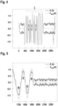
- Figure 4 shows the time course of the sampled received signal x ( k ) and, in comparison, the target output signal y should ( k ), which corresponds to an ideal signal course.
- Figure 5 shows an enlarged section of Figure 4 .
- Figure 4 I represents an area in which a barcode 8 is read.
- Figure 6 shows the time course of the output signal y( k ) obtained with the neural network 12 and, in comparison, the target output signal ysoll ( k ).
- Figure 7 shows an enlarged section of Figure 6 .
Description
Die Erfindung betrifft einen optischen Sensor und ein Verfahren zur Erfassung von Codes.The invention relates to an optical sensor and a method for detecting codes.
Derartige als Codeleser ausgebildete optische Sensoren dienen insbesondere zur Detektion von Barcodes. Die optischen Sensoren sind typischerweise als Scanner oder kamerabasierte Sensoren ausgebildet. Bei einem optischen Sensor in Form eines Scanners werden von einem Sender emittierte Lichtstrahlen mittels einer Ablenkeinheit periodisch innerhalb eines Erfassungsbereichs abgelenkt und dabei über einen zu detektierenden Barcode geführt. Die dadurch am Empfänger des optischen Sensors generierten Empfangssignale bilden ein amplitudenmoduliertes Intensitätssignal, wobei die Amplitudenmodulation entsprechend dem Kontrastmuster des Barcodes ausgebildet ist. Bei einem kamerabasierten optischen Sensor ist als Empfänger ein Bildsensor vorgesehen, mit dem ebenfalls ein amplitudenmoduliertes Intensitätssignal des Barcodes erhalten wird.Such optical sensors designed as code readers are used in particular to detect barcodes. The optical sensors are typically designed as scanners or camera-based sensors. With an optical sensor in the form of a scanner, light beams emitted by a transmitter are periodically deflected within a detection area by means of a deflection unit and thereby guided over a barcode to be detected. The received signals thereby generated at the receiver of the optical sensor form an amplitude-modulated intensity signal, the amplitude modulation being designed in accordance with the contrast pattern of the barcode. In the case of a camera-based optical sensor, an image sensor is provided as a receiver, with which an amplitude-modulated intensity signal of the barcode is also obtained.
Die Codeerfassung erfolgt typischerweise derart, dass die Empfangssignale des Empfängers differenziert werden und dann über einen Analog-Digital-Wandler einer Auswerteeinheit zugeführt werden, wo anhand der differenzierten und mit dem Analog-Digital-Wandler abgetasteten und digitalisierten Empfangssignale eine Dekodierung des Codes erfolgt. Hierzu werden die Kantenlagen von in den Codes vorhandenen Hell-Dunkel-Übergängen anhand der Extremstellen des differenzierten, abgetasteten Empfangssignals bestimmt.The code is typically captured in such a way that the received signals from the receiver are differentiated and then fed to an evaluation unit via an analog-digital converter, where the code is decoded based on the differentiated received signals sampled and digitized with the analog-digital converter. For this purpose, the edge positions of light-dark transitions present in the codes are determined based on the extreme points of the differentiated, sampled received signal.
Ein wesentliches Problem besteht darin, dass aufgrund der in den Applikationen auftretenden sehr unterschiedlichen Lesesituationen die Pegel der bei der Abtastung von Codes erhaltenen Empfangssignale sehr stark variieren. Dies führt dazu, dass der begrenzte Aussteuerbereich des Analog-Digital-Wandlers überschritten wird, so dass das Signal am Ausgang des Analog-Digital-Wandlers begrenzt wird. Diese Begrenzung verursacht, dass Informationen der differenzierten Empfangssignale, insbesondere Informationen über Kantenlagen, die für die Erfassung von Codes wesentlich sind, verloren gehen. Dies wiederum führt zu Fehldetektionen bei der Detektion der Codes.A major problem is that due to the very different reading situations that occur in the applications, the levels of the Receive signals obtained by scanning codes vary greatly. This results in the limited control range of the analogue-digital converter being exceeded, so that the signal at the output of the analogue-digital converter is limited. This limitation causes information from the differentiated received signals, in particular information about edge positions, which is essential for the detection of codes, to be lost. This in turn leads to incorrect detections when detecting the codes.
Prinzipiell kann diesem Problem dadurch begegnet werden, dass Kompressionsschaltungen eingesetzt werden, mittels derer die Pegel der Empfangssignale künstlich begrenzt werden. Da mit diesen Kompressionsschaltungen nur die Nutzsignalanteile, nicht aber die Rauschanteile der Empfangssignale reduziert werden, wird der Signal-/Rauschabstand in den Empfangssignalen reduziert, was wiederum zu fehlerhaften Codedetektionen führt.In principle, this problem can be addressed by using compression circuits that artificially limit the levels of the received signals. Since these compression circuits only reduce the useful signal components, but not the noise components of the received signals, the signal-to-noise ratio in the received signals is reduced, which in turn leads to incorrect code detections.
Die
In der
In der
In
Die
Der Erfindung liegt die Aufgabe zugrunde, bei einem optischen Sensor der eingangs genannten Art die Fehlersicherheit bei der Detektion von Codes zu verbessern.The
The invention is based on the object of improving the error security in the detection of codes in an optical sensor of the type mentioned.
Zur Lösung dieser Aufgabe sind die Merkmale der unabhängigen Ansprüche vorgesehen. Vorteilhafte Ausführungsformen und zweckmäßige Weiterbildungen der Erfindung sind in den abhängigen Ansprüchen beschrieben.The features of the independent claims are intended to solve this problem. Advantageous embodiments and useful developments of the invention are described in the dependent claims.
Die Erfindung betrifft einen optischen Sensor zur Erfassung von Codes, mit einem Lichtstrahlen emittierenden Sender und einem Lichtstrahlen empfangenden Empfänger, welche zur Abtastung von Codes ausgebildet sind, und mit einer Auswerteeinheit, welche zur Ermittlung von Codeinformationen der Codes in Abhängigkeit von Empfangssignalen des Empfängers ausgebildet ist. Die Empfangssignale des Empfängers sind einer Auswerteschaltung zugeführt, in welcher aus den Empfangssignalen abgetastete Empfangssignale generiert werden. Ein neuronales System ist vorgesehen, wobei die Auswerteschaltung einen Differenzierer, in welchem die Empfangssignale differenziert werden, und einen diesem nachgeordneten Analog-Digital-Wandler aufweist. Die im Analog-Digital-Wandler generierten abgetasteten Empfangssignale werden der Auswerteeinheit zugeführt, wobei das neuronale System Bestandteil der Auswerteeinheit ist. Die Auswerteeinheit weist eine Einheit zur Kantendetektion auf, wobei durch das neuronale System durch die Begrenzung der Pegel der Empfangssignale verloren gegangene Codeinformationen zumindest teilweise wiedergewonnen und dadurch Begrenzungen der Pegel der abgetasteten Empfangssignale kompensiert werden.The invention relates to an optical sensor for detecting codes, with a transmitter emitting light beams and a receiver receiving light beams, which are designed to scan codes, and with an evaluation unit which is used to determine code information of the codes in Dependence on received signals from the receiver is formed. The received signals from the receiver are fed to an evaluation circuit in which sampled received signals are generated from the received signals. A neural system is provided, the evaluation circuit having a differentiator in which the received signals are differentiated and an analog-digital converter downstream of it. The sampled received signals generated in the analog-digital converter are fed to the evaluation unit, with the neural system being part of the evaluation unit. The evaluation unit has a unit for edge detection, with the neural system at least partially recovering code information that was lost by limiting the levels of the received signals and thereby compensating for limitations in the levels of the sampled received signals.
Die Erfindung betrifft weiterhin ein Verfahren zur Erfassung von Codes.The invention further relates to a method for detecting codes.
Der Grundgedanke der Erfindung besteht somit darin, in den abgetasteten Empfangssignalen am Ausgang der Auswerteschaltung vorhandene Begrenzungen mit einem neuronalen System zu kompensieren. Mit der im neuronalen System durchgeführten Kompensation kann zumindest näherungsweise die Begrenzung der abgetasteten Empfangssignale, die durch die Auswerteschaltung verursacht ist, zumindest teilweise wieder rückgängig gemacht werden. Damit können Informationen über abgetastete Codes, die durch die Begrenzung verloren gingen, zumindest teilweise wiedergewonnen werden. Dadurch kann die Fehlersicherheit bei der Detektion der Codes erheblich erhöht werden.The basic idea of the invention is therefore to compensate for limitations present in the sampled received signals at the output of the evaluation circuit using a neural system. With the compensation carried out in the neural system, the limitation of the sampled received signals, which is caused by the evaluation circuit, can at least partially be reversed. This means that information about scanned codes that were lost due to the limitation can be at least partially recovered. This can significantly increase the error security when detecting the codes.
Erfindungsgemäß weist die Auswerteschaltung einen Differenzierer, in welchem die Empfangssignale differenziert werden, und einen diesem nachgeordneten Analog-Digital-Wandler auf.According to the invention, the evaluation circuit has a differentiator, in which the received signals are differentiated, and an analog-digital converter downstream of it.
Daran angepasst weist die Auswerteeinheit eine Einheit zur Kantendetektion auf.Adapted to this, the evaluation unit has a unit for edge detection.
Anhand der im Differenzierer differenzierten Empfangssignale erfolgt in der Einheit zur Kantendetektion die Bestimmung von Kantenlagen von Hell-Dunkel-Übergängen von gelesenen Codes dadurch, dass die Extremstellen in den differenzierten Empfangssignalen bestimmt werden.Based on the received signals differentiated in the differentiator, edge positions of light-dark transitions of read codes are determined in the edge detection unit by determining the extreme points in the differentiated received signals.
Um die im Differenzierer differenzierten Empfangssignale der Auswerteeinheit und der darin integrierten Einheit zur Kantendetektion zuzuführen, werden diese im Analog-Digital-Wandler abgetastet und digitalisiert. Die so am Ausgang des Analog-Digital-Wandler anstehenden abgetasteten Empfangssignale können dann direkt in die Auswerteeinheit eingelesen werden.In order to supply the received signals differentiated in the differentiator to the evaluation unit and the edge detection unit integrated therein, they are sampled and digitized in the analog-digital converter. The sampled received signals present at the output of the analog-digital converter can then be read directly into the evaluation unit.
Aufgrund der unterschiedlichen Lesesituationen in den Applikationen, in welchen der optische Sensor eingesetzt wird, variieren die Pegel der Empfangssignale sehr stark, so dass diese im Analog-Digital-Wandler aufgrund dessen begrenzten Aussteuerbereichs begrenzt werden, wodurch Informationen in den Empfangssignalen über die gelesenen Codes verloren gehen.Due to the different reading situations in the applications in which the optical sensor is used, the levels of the received signals vary greatly, so that these in the analog-digital converter limited control range, as a result of which information in the received signals about the read codes is lost.
Durch das dem Analog-Digital-Wandler nachgeordnete und der Einheit zur Kantendetektion vorgeordnete neuronale System können die durch die Begrenzung des Analog-Digital-Wandlers verlorengegangenen Codeinformationen zumindest teilweise wiedergewonnen werden, so dass eine sichere Dekodierung und damit Erfassung des Codes gewährleistet ist.The neural system downstream of the analog-digital converter and upstream of the edge detection unit can at least partially recover the code information lost due to the limitation of the analog-digital converter, so that reliable decoding and thus detection of the code is guaranteed.
Der erfindungsgemäße optische Sensor ist vorteilhaft als Scanner oder als Kamerasensor ausgebildet.The optical sensor according to the invention is advantageously designed as a scanner or as a camera sensor.
Zweckmäßig ist dabei der optische Sensor zur Erfassung von Barcodes ausgebildet.The optical sensor is expediently designed to detect barcodes.
Die Barcodes bestehen aus einer linearen Folge von hellen und dunklen Modulen. Zur Dekodierung der Barcodes werden die Kantenlagen der Hell-Dunkel-Übergänge dieser Module erfasst.The barcodes consist of a linear sequence of light and dark modules. To decode the barcodes, the edge positions of the light-dark transitions of these modules are recorded.
Vorteilhaft ist der optische Sensor derart ausgebildet, dass mit diesem innerhalb eines Lesebereichs Codes erfassbar sind.The optical sensor is advantageously designed in such a way that codes can be detected within a reading range.
Damit können mit dem optischen Sensor Codes nicht nur in einem einzigen Leseabstand sondern in einem ausgedehnten Lesebereich erfasst werden, was generell durch geeignete Optikelemente, die dem Sender und/oder Empfänger des optischen Sensors zugeordnet sind, erreicht wird.This means that the optical sensor can be used to detect codes not only at a single reading distance but also over an extended reading range, which is generally achieved by suitable optical elements that are assigned to the transmitter and/or receiver of the optical sensor.
Das neuronale System kann dabei vorteilhaft als neuronales Netz ausgebildet sein.The neural system can advantageously be designed as a neural network.
Damit mit dem neuronalen System in abgetasteten Empfangssignalen verlorengegangene Codeinformationen wiederhergestellt werden können, sind für ein Training eine Anzahl von abgetasteten Empfangssignalen und zugeordneten Soll-Ausgangssignalen am Ausgang des neuronalen Systems vorgegeben.So that code information lost in sampled received signals can be restored using the neural system, a Training a number of sampled received signals and assigned target output signals are specified at the output of the neural system.
Dabei werden zweckmäßig im Training abgetastete Empfangssignale und zugeordnete Soll-Ausgangssignale für unterschiedliche Lesesituationen vorgegeben.Reception signals sampled during training and assigned target output signals for different reading situations are expediently specified.
Mit dem Training werden die Parameter des neuronalen Systems bestimmt, wobei vorteilhaft ist, wenn die hierzu verwendeten abgetasteten Empfangssignale und Soll-Ausgangssignale möglichst viele unterschiedliche Lesesituationen abdecken, so dass eine entsprechend breite und umfangreiche Anpassung des neuronalen Netzes an die möglichen Lesesituationen gegeben ist.With the training, the parameters of the neural system are determined, and it is advantageous if the sampled received signals and target output signals used for this cover as many different reading situations as possible, so that a correspondingly broad and extensive adaptation of the neural network to the possible reading situations is ensured.
Die unterschiedlichen Lesesituationen können unterschiedliche Rauschamplituden, Signalfrequenzen oder auch unterschiedliche Verhältnisse der Fleckdurchmesser der Lichtstrahlen des optischen Sensors im Verhältnis zu Modulbreiten von zu lesenden Codes sein.The different reading situations can be different noise amplitudes, signal frequencies or even different ratios of the spot diameters of the light beams of the optical sensor in relation to module widths of codes to be read.
Durch das auf diese Weise durchgeführte Training ist es möglich, dass das neuronale System zur Durchführung einer Rauschunterdrückung ausgebildet ist.The training carried out in this way makes it possible for the neural system to be trained to carry out noise suppression.
Weiterhin kann mittels des neuronalen Systems der Lesebereich des optischen Sensors vergrößerbar sein.Furthermore, the reading range of the optical sensor can be enlarged by means of the neural system.
Damit wird die Funktionalität des erfindungsgemäßen optischen Sensors erheblich verbessert.This significantly improves the functionality of the optical sensor according to the invention.
Die Erfindung wird im Folgenden anhand der Zeichnungen erläutert. Es zeigen:
- Figur 1:
- Erstes Ausführungsbeispiel von Sensorkomponenten des erfindungsgemäßen optischen Sensors.
- Figur 2:
- Zweites Ausführungsbeispiel von Sensorkomponenten des erfindungsgemäßen optischen Sensors.
- Figur 3:
- Blockschaltbild des erfindungsgemäßen optischen Sensors.
- Figur 4:
- Zeitlicher Verlauf von abgetasteten Empfangssignalen am Ausgang der Auswerteschaltung des optischen Sensors gemäß
Figur 3 - Figur 5:
- Vergrößerte Teildarstellung der Verläufe gemäß
Figur 4 - Figur 6:
- Zeitlicher Verlauf der Ausgangssignale des neuronalen Systems des optischen Sensors gemäß
Figur 3 - Figur 7:
- Vergrößerte Teildarstellung der Verläufe gemäß
Figur 6 .
- Figure 1:
- First embodiment of sensor components of the optical sensor according to the invention.
- Figure 2:
- Second exemplary embodiment of sensor components of the optical sensor according to the invention.
- Figure 3:
- Block diagram of the optical sensor according to the invention.
- Figure 4:
- Time course of sampled received signals at the output of the evaluation circuit of the optical sensor according to
Figure 3 . - Figure 5:
- Enlarged partial representation of the courses according to
Figure 4 . - Figure 6:
- Time course of the output signals of the neural system of the optical sensor according to
Figure 3 compared to target output signals. - Figure 7:
- Enlarged partial representation of the courses according to
Figure 6 .
Der optische Sensor 1 weist einen Lichtstrahlen 2 emittierenden Sender 3 und einen Lichtstrahlen 2 empfangenden Empfänger 4 auf. Der Sender 3 kann von einer Leuchtdiode oder Laserdiode gebildet sein, der Empfänger 4 kann von einer Photodiode gebildet sein. Die Lichtstrahlen 2 werden über eine Ablenkeinheit periodisch innerhalb eines Erfassungsbereichs abgelenkt. Im vorliegenden Fall besteht die Ablenkeinheit aus einem motorisch getriebenen Polygonspiegelrad 5. Das Polygonspiegelrad 5 ist um eine senkrecht zur Zeichenebene verlaufende Drehachse drehbar. Die Lichtstrahlen 2 werden an den Facetten 6 des Polygonspiegelrads 5 abgelenkt.The
Dadurch werden die Lichtstrahlen 2 über einen auf einem Objekt 7 angeordneten Barcode 8 geführt, der in bekannter Weise aus einer Folge von hellen und dunklen Strichelementen besteht. Die bei der Detektion des Barcodes 8 erhaltenen Empfangssignale des Empfängers 4 bilden ein amplitudenmoduliertes Intensitätssignal, wobei in der Amplitudenmodulation des Intensitätssignals das Kontrastmuster des Barcodes 8 enthalten ist.As a result, the light beams 2 are guided over a
Die am Ausgang des Analog-Digital-Wandlers 11 anstehenden abgetasteten Empfangssignale x(k) werden einer Auswerteeinheit in Form einer Rechnereinheit zugeführt. Die Auswerteeinheit weist ein neuronales Netz 12 und eine diesem nachgeordnete Einheit zur Kantendetektion 13 auf.The sampled received signals x(k) present at the output of the analog-
Die Barcodes 8 weisen eine Folge von hellen und dunklen Modulen auf. Die Auswertung zur Dekodierung der Barcodes 8 erfolgt in der Einheit zur Kantentendetektion 13 derart, dass anhand der differenzierten Empfangssignale die Kantenlagen der Hell-Dunkel-Übergänge der Barcodes 8 erfasst werden, die durch die Extremstellen der differenzierten Empfangssignale gegeben sind.The
Durch den begrenzten Aussteuerbereich des Analog-Digital-Wandlers 11 erfolgt je nach Pegel der Empfangssignale, die zusätzlich zu den differenzierten Empfangssignalen in der Auswerteeinheit zur Detektion der Barcodes 8 herangezogen werden, eine Begrenzung der differenzierten Empfangssignale, wodurch Informationen über die Barcodes 8 verloren gehen.Due to the limited control range of the analog-
Erfindungsgemäß erfolgt im neuronalen Netz 12 eine Kompensation der Begrenzung vom Analog-Digital-Wandler 11 eingelesenen abgetasteten Empfangssignalen. Durch diese Kompensation werden Begrenzungen in den abgetasteten Empfangssignalen rückgängig gemacht, so dass verlorene Kanteninformationen in den abgetasteten Empfangssignalen in den Ausgangssignalen y(k) des neuronalen Netzes 12 wiedergewonnen werden.According to the invention, the limitation of sampled received signals read in by the analog-
Hierzu erfolgt für das neuronale Netz 12 ein Training, das vor dem Arbeitsbetrieb des optischen Sensors 1 durchgeführt wird.For this purpose, the
Für ein solches Training wird eine möglichst große Anzahl von abgetasteten Empfangssignalen und zugeordneten Soll-Ausgangssignalen vorgegeben. Vorteilhaft werden im Training abgetastete Empfangssignale und zugeordnete Soll-Ausgangssignale für unterschiedliche Lesesituationen vorgegeben.For such training, the largest possible number of sampled received signals and assigned target output signals is specified. Advantageously, received signals sampled during training and assigned target output signals are specified for different reading situations.
Mit dem durch das Training optimierten neuronalen Netz 12 werden nicht nur Verluste von Kanteninformationen in den differenzierten Empfangssignalen wiedergewonnen. Vielmehr wird mit dem neuronalen Netz 12 auch eine Rauschunterdrückung erzielt. Zudem kann mit dem neuronalen Netz 12 der Lesebereich des neuronalen Netzes 12 vergrößert werden.With the
Die Wirkungsweise des neuronalen Netzes 12 ist in den
In
Wie
Wie
- (1)(1)
- Optischer SensorOptical sensor
- (2)(2)
- LichtstrahlRay of light
- (3)(3)
- SenderChannel
- (4)(4)
- EmpfängerRecipient
- (5)(5)
- PolygonspiegelradPolygon mirror wheel
- (6)(6)
- Facettefacet
- (7)(7)
- Objektobject
- (8)(8th)
- BarcodeBarcode
- (9)(9)
- Scanner FrontendScanner front end
- (10)(10)
- DifferenziererDifferentiator
- (11)(11)
- Analog-Digital-WandlerAnalog-to-digital converter
- (12)(12)
- Neuronales NetzNeural network
- (13)(13)
- Einheit zur KantendetektionEdge detection unit
Claims (11)
- An optical sensor (1) for detecting codes, having a transmitter (3) emitting light beams (2) and a receiver (4) receiving light beams (2), which are designed to scan codes, and having an evaluation unit which is designed to determine code information of the codes as a function of received signals of the receiver (4), characterised in that the received signals of the receiver (4) are fed to an evaluation circuit in which sampled received signals are generated from the received signals, and in that a neural system is provided, the evaluation circuit comprising a differentiator (10), in which the received signals are differentiated, and an analogue-to-digital converter (11) arranged downstream thereof, wherein the sampled received signals generated in the analogue-to-digital converter (11) are fed to the evaluation unit, wherein the neural system is a component of the evaluation unit and wherein the evaluation unit has a unit for edge detection (13), wherein code information lost due to the limitation of the levels of the received signals caused by the evaluation circuit is at least partially recovered by the neural system and thereby limitations of the levels of the sampled received signals are compensated.
- An optical sensor (1) according to claim 1, characterised in that the neural system is a neural network (12).
- An optical sensor (1) according to one of claims 1 or 2, characterised in that the unit for edge detection (13) is arranged downstream of the neural system.
- An optical sensor (1) according to one of claims 1 to 3, characterised in that it is designed to detect barcodes (8).
- An optical sensor (1) according to one of claims 1 to 4, characterised in that it is designed as a scanner or as a camera sensor.
- An optical sensor (1) according to one of claims 1 to 5, characterised in that it can be used to detect codes within a reading range.
- An optical sensor (1) according to one of claims 1 to 6, characterised in that a number of sampled received signals and assigned target output signals are predetermined at the output of the neuronal system for training.
- An optical sensor (1) according to claim 7, characterised in that sampled received signals and assigned setpoint output signals for different reading situations are specified during training.
- An optical sensor (1) according to claim 8, characterised in that the neural system is designed to perform noise suppression.
- An optical sensor (1) according to one of claims 8 or 9, characterised in that the reading range can be enlarged by means of the neuronal system.
- A method for detecting codes, having a transmitter (3) emitting light beams (2) and a receiver (4) receiving light beams (2), which are designed to scan codes, and having an evaluation unit which is designed to determine code information of the codes as a function of received signals of the receiver (4), characterised in that the received signals of the receiver (4) are fed to an evaluation circuit in which sampled received signals are generated from the received signals, and in that a neurological system is provided, the evaluation circuit comprising a differentiator (10), in which the received signals are differentiated, and an analogue-to-digital converter (11) arranged downstream thereof, wherein the sampled received signals generated in the analogue-to-digital converter (11) are fed to the evaluation unit, wherein the neural system is a component of the evaluation unit and wherein the evaluation unit has a unit for edge detection (13), wherein code information lost due to the limitation of the levels of the received signals caused by the evaluation circuit is at least partially recovered by the neural system and thereby limitations of the levels of the sampled received signals are compensated.
Priority Applications (1)
| Application Number | Priority Date | Filing Date | Title |
|---|---|---|---|
| EP21151994.7A EP4030337B1 (en) | 2021-01-18 | 2021-01-18 | Optical sensor and method for detecting codes |
Applications Claiming Priority (1)
| Application Number | Priority Date | Filing Date | Title |
|---|---|---|---|
| EP21151994.7A EP4030337B1 (en) | 2021-01-18 | 2021-01-18 | Optical sensor and method for detecting codes |
Publications (2)
| Publication Number | Publication Date |
|---|---|
| EP4030337A1 EP4030337A1 (en) | 2022-07-20 |
| EP4030337B1 true EP4030337B1 (en) | 2024-03-13 |
Family
ID=74187129
Family Applications (1)
| Application Number | Title | Priority Date | Filing Date |
|---|---|---|---|
| EP21151994.7A Active EP4030337B1 (en) | 2021-01-18 | 2021-01-18 | Optical sensor and method for detecting codes |
Country Status (1)
| Country | Link |
|---|---|
| EP (1) | EP4030337B1 (en) |
Citations (1)
| Publication number | Priority date | Publication date | Assignee | Title |
|---|---|---|---|---|
| EP3428834B1 (en) * | 2017-07-12 | 2019-06-12 | Sick AG | Optoelectronic code reader and method for reading optical codes |
Family Cites Families (4)
| Publication number | Priority date | Publication date | Assignee | Title |
|---|---|---|---|---|
| JP2729088B2 (en) * | 1989-09-22 | 1998-03-18 | 富士通株式会社 | Barcode reader processing unit |
| DE10137093A1 (en) * | 2001-07-30 | 2003-02-13 | Sick Ag | Recognition of a code, particularly a two-dimensional matrix type code, within a graphical background or image whereby recognition is undertaken using a neuronal network |
| DE102004059604B4 (en) * | 2004-12-10 | 2006-07-27 | Leuze Electronic Gmbh & Co Kg | Optoelectronic detector for marks on contrast model, has transmitter and receiver forming distance sensor element and also linkage of detected distance value and amplitude value for elimination of disturbing signal portions |
| DE102018109392A1 (en) * | 2018-04-19 | 2019-10-24 | Beckhoff Automation Gmbh | METHOD FOR DETECTING OPTICAL CODES, AUTOMATION SYSTEM AND COMPUTER PROGRAM PRODUCT TO PERFORM THE PROCESS |
-
2021
- 2021-01-18 EP EP21151994.7A patent/EP4030337B1/en active Active
Patent Citations (1)
| Publication number | Priority date | Publication date | Assignee | Title |
|---|---|---|---|---|
| EP3428834B1 (en) * | 2017-07-12 | 2019-06-12 | Sick AG | Optoelectronic code reader and method for reading optical codes |
Also Published As
| Publication number | Publication date |
|---|---|
| EP4030337A1 (en) | 2022-07-20 |
Similar Documents
| Publication | Publication Date | Title |
|---|---|---|
| DE4036967C2 (en) | Arrangement for reading bar codes | |
| DE19882768B3 (en) | Second order differentiating signal processor for a bar code scanner and signal processing method for using bar code scanners | |
| DE10312972B3 (en) | Optical sensor for detecting objects within surveillance zone with selection of different protected fields within latter by activation signals received via bidirectional data communications interface | |
| DE69637397T2 (en) | Optical barcode scanner | |
| EP4030337B1 (en) | Optical sensor and method for detecting codes | |
| EP1207491B1 (en) | Optoelectronic device | |
| DE102017211707A1 (en) | Method and LIDAR device for scanning a scanning area with at least two pulse-coded beams | |
| EP0686290B1 (en) | Opto-electronic device for recognizing bar-code symbols | |
| DE10113641B4 (en) | Optoelectronic device | |
| DE69930984T2 (en) | Optical device for scanning and encoding a bar code | |
| WO2021249845A1 (en) | Method and device for identifying contamination on a protective screen of a lidar sensor | |
| EP3312761B1 (en) | Method for recording bar codes using a code reader | |
| DE10207180B4 (en) | Method for marking objects by means of bar codes and device for reading bar codes | |
| EP1927933B1 (en) | Bar code reader | |
| DE19504912C2 (en) | Method and device for recognizing barcode symbols | |
| EP1583021B1 (en) | Opto-electronic device for recognising bar code symbols | |
| DE69735834T2 (en) | Method and device for recording data assigned to objects | |
| DE102017119321A1 (en) | SURROUNDING SENSOR WITH SIGNAL IDENTIFICATION | |
| EP3926519A1 (en) | Optical sensor and method for detecting codes | |
| DE3203720A1 (en) | DEVICE FOR DETECTING OPTICAL CODE STAGS APPLIED TO ITEMS | |
| EP1602944B1 (en) | Optical sensor | |
| DE4424008A1 (en) | Opto electronic scanning system for bar code | |
| DE102004059604B4 (en) | Optoelectronic detector for marks on contrast model, has transmitter and receiver forming distance sensor element and also linkage of detected distance value and amplitude value for elimination of disturbing signal portions | |
| DE19537953C2 (en) | Optoelectronic device and method for recognizing barcode symbols | |
| EP3399336B1 (en) | Positioning device |
Legal Events
| Date | Code | Title | Description |
|---|---|---|---|
| PUAI | Public reference made under article 153(3) epc to a published international application that has entered the european phase |
Free format text: ORIGINAL CODE: 0009012 |
|
| STAA | Information on the status of an ep patent application or granted ep patent |
Free format text: STATUS: REQUEST FOR EXAMINATION WAS MADE |
|
| 17P | Request for examination filed |
Effective date: 20210721 |
|
| AK | Designated contracting states |
Kind code of ref document: A1 Designated state(s): AL AT BE BG CH CY CZ DE DK EE ES FI FR GB GR HR HU IE IS IT LI LT LU LV MC MK MT NL NO PL PT RO RS SE SI SK SM TR |
|
| GRAP | Despatch of communication of intention to grant a patent |
Free format text: ORIGINAL CODE: EPIDOSNIGR1 |
|
| STAA | Information on the status of an ep patent application or granted ep patent |
Free format text: STATUS: GRANT OF PATENT IS INTENDED |
|
| INTG | Intention to grant announced |
Effective date: 20240102 |
|
| GRAS | Grant fee paid |
Free format text: ORIGINAL CODE: EPIDOSNIGR3 |
|
| GRAA | (expected) grant |
Free format text: ORIGINAL CODE: 0009210 |
|
| STAA | Information on the status of an ep patent application or granted ep patent |
Free format text: STATUS: THE PATENT HAS BEEN GRANTED |
|
| AK | Designated contracting states |
Kind code of ref document: B1 Designated state(s): AL AT BE BG CH CY CZ DE DK EE ES FI FR GB GR HR HU IE IS IT LI LT LU LV MC MK MT NL NO PL PT RO RS SE SI SK SM TR |
|
| REG | Reference to a national code |
Ref country code: GB Ref legal event code: FG4D Free format text: NOT ENGLISH |
|
| REG | Reference to a national code |
Ref country code: CH Ref legal event code: EP |
|
| REG | Reference to a national code |
Ref country code: DE Ref legal event code: R096 Ref document number: 502021002935 Country of ref document: DE |