EP4030227A1 - Pallet - Google Patents
Pallet Download PDFInfo
- Publication number
- EP4030227A1 EP4030227A1 EP19919565.2A EP19919565A EP4030227A1 EP 4030227 A1 EP4030227 A1 EP 4030227A1 EP 19919565 A EP19919565 A EP 19919565A EP 4030227 A1 EP4030227 A1 EP 4030227A1
- Authority
- EP
- European Patent Office
- Prior art keywords
- pallet
- pallet body
- resin sheet
- legs
- step portion
- Prior art date
- Legal status (The legal status is an assumption and is not a legal conclusion. Google has not performed a legal analysis and makes no representation as to the accuracy of the status listed.)
- Granted
Links
Images




Classifications
-
- B—PERFORMING OPERATIONS; TRANSPORTING
- B65—CONVEYING; PACKING; STORING; HANDLING THIN OR FILAMENTARY MATERIAL
- B65D—CONTAINERS FOR STORAGE OR TRANSPORT OF ARTICLES OR MATERIALS, e.g. BAGS, BARRELS, BOTTLES, BOXES, CANS, CARTONS, CRATES, DRUMS, JARS, TANKS, HOPPERS, FORWARDING CONTAINERS; ACCESSORIES, CLOSURES, OR FITTINGS THEREFOR; PACKAGING ELEMENTS; PACKAGES
- B65D19/00—Pallets or like platforms, with or without side walls, for supporting loads to be lifted or lowered
- B65D19/0004—Rigid pallets without side walls
- B65D19/0006—Rigid pallets without side walls the load supporting surface being made of a single element
- B65D19/0008—Rigid pallets without side walls the load supporting surface being made of a single element forming a continuous plane contact surface
- B65D19/002—Rigid pallets without side walls the load supporting surface being made of a single element forming a continuous plane contact surface the base surface being made of more than one element
- B65D19/0024—Rigid pallets without side walls the load supporting surface being made of a single element forming a continuous plane contact surface the base surface being made of more than one element forming discontinuous or non-planar contact surfaces
- B65D19/0028—Rigid pallets without side walls the load supporting surface being made of a single element forming a continuous plane contact surface the base surface being made of more than one element forming discontinuous or non-planar contact surfaces and each contact surface having a discrete foot-like shape
-
- B—PERFORMING OPERATIONS; TRANSPORTING
- B29—WORKING OF PLASTICS; WORKING OF SUBSTANCES IN A PLASTIC STATE IN GENERAL
- B29C—SHAPING OR JOINING OF PLASTICS; SHAPING OF MATERIAL IN A PLASTIC STATE, NOT OTHERWISE PROVIDED FOR; AFTER-TREATMENT OF THE SHAPED PRODUCTS, e.g. REPAIRING
- B29C51/00—Shaping by thermoforming, i.e. shaping sheets or sheet like preforms after heating, e.g. shaping sheets in matched moulds or by deep-drawing; Apparatus therefor
- B29C51/26—Component parts, details or accessories; Auxiliary operations
- B29C51/30—Moulds
- B29C51/36—Moulds specially adapted for vacuum forming, Manufacture thereof
-
- B—PERFORMING OPERATIONS; TRANSPORTING
- B29—WORKING OF PLASTICS; WORKING OF SUBSTANCES IN A PLASTIC STATE IN GENERAL
- B29C—SHAPING OR JOINING OF PLASTICS; SHAPING OF MATERIAL IN A PLASTIC STATE, NOT OTHERWISE PROVIDED FOR; AFTER-TREATMENT OF THE SHAPED PRODUCTS, e.g. REPAIRING
- B29C51/00—Shaping by thermoforming, i.e. shaping sheets or sheet like preforms after heating, e.g. shaping sheets in matched moulds or by deep-drawing; Apparatus therefor
- B29C51/10—Forming by pressure difference, e.g. vacuum
-
- B—PERFORMING OPERATIONS; TRANSPORTING
- B29—WORKING OF PLASTICS; WORKING OF SUBSTANCES IN A PLASTIC STATE IN GENERAL
- B29L—INDEXING SCHEME ASSOCIATED WITH SUBCLASS B29C, RELATING TO PARTICULAR ARTICLES
- B29L2031/00—Other particular articles
- B29L2031/712—Containers; Packaging elements or accessories, Packages
- B29L2031/7178—Pallets
-
- B—PERFORMING OPERATIONS; TRANSPORTING
- B65—CONVEYING; PACKING; STORING; HANDLING THIN OR FILAMENTARY MATERIAL
- B65D—CONTAINERS FOR STORAGE OR TRANSPORT OF ARTICLES OR MATERIALS, e.g. BAGS, BARRELS, BOTTLES, BOXES, CANS, CARTONS, CRATES, DRUMS, JARS, TANKS, HOPPERS, FORWARDING CONTAINERS; ACCESSORIES, CLOSURES, OR FITTINGS THEREFOR; PACKAGING ELEMENTS; PACKAGES
- B65D2519/00—Pallets or like platforms, with or without side walls, for supporting loads to be lifted or lowered
- B65D2519/00004—Details relating to pallets
- B65D2519/00009—Materials
- B65D2519/00014—Materials for the load supporting surface
- B65D2519/00034—Plastic
-
- B—PERFORMING OPERATIONS; TRANSPORTING
- B65—CONVEYING; PACKING; STORING; HANDLING THIN OR FILAMENTARY MATERIAL
- B65D—CONTAINERS FOR STORAGE OR TRANSPORT OF ARTICLES OR MATERIALS, e.g. BAGS, BARRELS, BOTTLES, BOXES, CANS, CARTONS, CRATES, DRUMS, JARS, TANKS, HOPPERS, FORWARDING CONTAINERS; ACCESSORIES, CLOSURES, OR FITTINGS THEREFOR; PACKAGING ELEMENTS; PACKAGES
- B65D2519/00—Pallets or like platforms, with or without side walls, for supporting loads to be lifted or lowered
- B65D2519/00004—Details relating to pallets
- B65D2519/00009—Materials
- B65D2519/00049—Materials for the base surface
- B65D2519/00069—Plastic
-
- B—PERFORMING OPERATIONS; TRANSPORTING
- B65—CONVEYING; PACKING; STORING; HANDLING THIN OR FILAMENTARY MATERIAL
- B65D—CONTAINERS FOR STORAGE OR TRANSPORT OF ARTICLES OR MATERIALS, e.g. BAGS, BARRELS, BOTTLES, BOXES, CANS, CARTONS, CRATES, DRUMS, JARS, TANKS, HOPPERS, FORWARDING CONTAINERS; ACCESSORIES, CLOSURES, OR FITTINGS THEREFOR; PACKAGING ELEMENTS; PACKAGES
- B65D2519/00—Pallets or like platforms, with or without side walls, for supporting loads to be lifted or lowered
- B65D2519/00004—Details relating to pallets
- B65D2519/00258—Overall construction
- B65D2519/00263—Overall construction of the pallet
- B65D2519/00273—Overall construction of the pallet made of more than one piece
-
- B—PERFORMING OPERATIONS; TRANSPORTING
- B65—CONVEYING; PACKING; STORING; HANDLING THIN OR FILAMENTARY MATERIAL
- B65D—CONTAINERS FOR STORAGE OR TRANSPORT OF ARTICLES OR MATERIALS, e.g. BAGS, BARRELS, BOTTLES, BOXES, CANS, CARTONS, CRATES, DRUMS, JARS, TANKS, HOPPERS, FORWARDING CONTAINERS; ACCESSORIES, CLOSURES, OR FITTINGS THEREFOR; PACKAGING ELEMENTS; PACKAGES
- B65D2519/00—Pallets or like platforms, with or without side walls, for supporting loads to be lifted or lowered
- B65D2519/00004—Details relating to pallets
- B65D2519/00258—Overall construction
- B65D2519/00283—Overall construction of the load supporting surface
- B65D2519/00288—Overall construction of the load supporting surface made of one piece
-
- B—PERFORMING OPERATIONS; TRANSPORTING
- B65—CONVEYING; PACKING; STORING; HANDLING THIN OR FILAMENTARY MATERIAL
- B65D—CONTAINERS FOR STORAGE OR TRANSPORT OF ARTICLES OR MATERIALS, e.g. BAGS, BARRELS, BOTTLES, BOXES, CANS, CARTONS, CRATES, DRUMS, JARS, TANKS, HOPPERS, FORWARDING CONTAINERS; ACCESSORIES, CLOSURES, OR FITTINGS THEREFOR; PACKAGING ELEMENTS; PACKAGES
- B65D2519/00—Pallets or like platforms, with or without side walls, for supporting loads to be lifted or lowered
- B65D2519/00004—Details relating to pallets
- B65D2519/00258—Overall construction
- B65D2519/00313—Overall construction of the base surface
- B65D2519/00323—Overall construction of the base surface made of more than one piece
-
- B—PERFORMING OPERATIONS; TRANSPORTING
- B65—CONVEYING; PACKING; STORING; HANDLING THIN OR FILAMENTARY MATERIAL
- B65D—CONTAINERS FOR STORAGE OR TRANSPORT OF ARTICLES OR MATERIALS, e.g. BAGS, BARRELS, BOTTLES, BOXES, CANS, CARTONS, CRATES, DRUMS, JARS, TANKS, HOPPERS, FORWARDING CONTAINERS; ACCESSORIES, CLOSURES, OR FITTINGS THEREFOR; PACKAGING ELEMENTS; PACKAGES
- B65D2519/00—Pallets or like platforms, with or without side walls, for supporting loads to be lifted or lowered
- B65D2519/00004—Details relating to pallets
- B65D2519/00258—Overall construction
- B65D2519/00313—Overall construction of the base surface
- B65D2519/00328—Overall construction of the base surface shape of the contact surface of the base
- B65D2519/00338—Overall construction of the base surface shape of the contact surface of the base contact surface having a discrete foot-like shape
-
- B—PERFORMING OPERATIONS; TRANSPORTING
- B65—CONVEYING; PACKING; STORING; HANDLING THIN OR FILAMENTARY MATERIAL
- B65D—CONTAINERS FOR STORAGE OR TRANSPORT OF ARTICLES OR MATERIALS, e.g. BAGS, BARRELS, BOTTLES, BOXES, CANS, CARTONS, CRATES, DRUMS, JARS, TANKS, HOPPERS, FORWARDING CONTAINERS; ACCESSORIES, CLOSURES, OR FITTINGS THEREFOR; PACKAGING ELEMENTS; PACKAGES
- B65D2519/00—Pallets or like platforms, with or without side walls, for supporting loads to be lifted or lowered
- B65D2519/00004—Details relating to pallets
- B65D2519/00258—Overall construction
- B65D2519/00398—Overall construction reinforcements
- B65D2519/00402—Integral, e.g. ribs
-
- B—PERFORMING OPERATIONS; TRANSPORTING
- B65—CONVEYING; PACKING; STORING; HANDLING THIN OR FILAMENTARY MATERIAL
- B65D—CONTAINERS FOR STORAGE OR TRANSPORT OF ARTICLES OR MATERIALS, e.g. BAGS, BARRELS, BOTTLES, BOXES, CANS, CARTONS, CRATES, DRUMS, JARS, TANKS, HOPPERS, FORWARDING CONTAINERS; ACCESSORIES, CLOSURES, OR FITTINGS THEREFOR; PACKAGING ELEMENTS; PACKAGES
- B65D2519/00—Pallets or like platforms, with or without side walls, for supporting loads to be lifted or lowered
- B65D2519/00004—Details relating to pallets
- B65D2519/00547—Connections
- B65D2519/00552—Structures connecting the constitutive elements of the pallet to each other, i.e. load supporting surface, base surface and/or separate spacer
- B65D2519/00557—Structures connecting the constitutive elements of the pallet to each other, i.e. load supporting surface, base surface and/or separate spacer without separate auxiliary elements
- B65D2519/00562—Structures connecting the constitutive elements of the pallet to each other, i.e. load supporting surface, base surface and/or separate spacer without separate auxiliary elements chemical connection, e.g. glued, welded, sealed
-
- B—PERFORMING OPERATIONS; TRANSPORTING
- B65—CONVEYING; PACKING; STORING; HANDLING THIN OR FILAMENTARY MATERIAL
- B65D—CONTAINERS FOR STORAGE OR TRANSPORT OF ARTICLES OR MATERIALS, e.g. BAGS, BARRELS, BOTTLES, BOXES, CANS, CARTONS, CRATES, DRUMS, JARS, TANKS, HOPPERS, FORWARDING CONTAINERS; ACCESSORIES, CLOSURES, OR FITTINGS THEREFOR; PACKAGING ELEMENTS; PACKAGES
- B65D2519/00—Pallets or like platforms, with or without side walls, for supporting loads to be lifted or lowered
- B65D2519/00004—Details relating to pallets
- B65D2519/00736—Details
- B65D2519/00825—Finishing of the external surfaces
Definitions
- the present invention relates to a pallet made of foamed resin, such as expanded polystyrene, used for transporting goods using a forklift, a hand-drawn pallet jack or the like.
- foamed resin such as expanded polystyrene
- a pallet made of foamed resin is known as a lighter pallet than the paper pallet (see, for example, Patent Document 1).
- the pallet made of foamed resin has fine irregularities on the surface due to the foamed beads, and there is a problem that the surface is fragile and rough compared to a pallet made of wood or plastic.
- such a resin pallet that the surface of the pallet body is covered with a resin sheet for reinforcement is known (for example, refer Patent Document 2).
- the foamed beads which constitute the foamed resin pallet, contain air in their almost entire volume, and therefore have low thermal conductivity and moderate elasticity. Therefore, the pallet made of foamed resin has a thermal insulation performance that makes it difficult for heat from a road surface, a warehouse floor, etc. to be transferred to the pallet, and also since the pallet made of foamed resin has a cushioning property unique to foamed resin, goods-conveyed can be protected from shocks.
- the present invention has been made in view of the above problems, and an object of the present invention is to provide a pallet having excellent thermal insulation performance and cushioning property with respect to loaded goods-conveyed while ensuring the strength of the outer surface of the pallet.
- the present invention provides a pallet comprising: a plate-like pallet body made of foamed resin; a plurality of legs provided on a bottom surface of the pallet body; and a resin sheet integrated by vacuum-forming from the bottom surface side of the pallet, wherein a top surface of the pallet body has a loading surface on which goods-conveyed is placed, and a step portion formed in a shape down-step from the outer peripheral edge of the loading surface to the side surface of the pallet body, and the resin sheet covers the bottom surface of the pallet body, the legs, the side surfaces of the pallet body and the step portion, and the loading surface is not covered with the resin sheet.
- the resin sheet has a thin sheet thickness at a portion covering the step portion.
- the pallet body and the legs are molded as separate bodies, and the bottom surface of the pallet body has an exhaust hole made in a thickness direction of the pallet body at a place where the leg is arranged.
- the bottom surface of the pallet body has a fitting concave into which the leg is fitted, and the exhaust hole is provided at a peripheral edge of the fitting concave.
- the exhaust hole does not penetrate to the top surface of the pallet body, and a thickness of 5 mm or more is provided from a bottom of the exhaust hole to the top surface of the pallet body.
- a ridge line portion between the step portion and the loading surface is chamfered to be a curved surface.
- the loading surface is an exposed surface of the foamed resin forming the pallet body and having a thermal insulation performance and a cushioning property.
- the resin sheet covers surfaces that are particularly susceptible to damage, such as the bottom surface of the pallet body, the places between the legs into which the fork are inserted, and the side surface of the pallet body, those outer surfaces can be strengthened.
- the loading surface of the pallet is not covered with the resin sheet, the foamed resin having the thermal insulation performance and cushioning property and forming the pallet body is exposed there.
- the foamed resin constituting the foamed resin pallet can contact directly with the goods placed on the pallet so as to be conveyed, and therefore it is possible to enjoy the high thermal insulation performance and the cushioning property unique to the foamed resin.
- the pallet 1 of this embodiment can be preferably used for the management and transportation of goods using a forklift, a hand-drawn pallet jack or the like at a distribution site or the like.
- the left front side of the pallet 1 shown in FIG. 1A is referred to as the front
- the right front side of the pallet 1 is referred to as the right side.
- the pallet 1 comprises a plate-like pallet body 2 made of foamed resin, a plurality of legs 3 provided on the bottom surface of the pallet body 2, and a resin sheet 4 that covers the outer surfaces of the pallet body 2 and the legs 3 (see FIG. 2 ).
- the plurality of legs 3 are arranged in a lattice pattern at predetermined intervals on the bottom surface of the pallet body 2.
- nine legs 3 of 3 ⁇ 3 are provided, each of which has a box-like shape with a substantially square projected area in plan view.
- the resin sheet 4 is shown in gray for convenience of explanation, but the resin sheet 4 may be transparent or the same white as the pallet body 2.
- the leg 3 is a support member that raises the height of the top surface 21 serving as the loading surface 20, and the plurality of legs 3 are arranged at predetermined intervals from the adjacent legs 3, thereby the fork insertion portion 10 into which a fork is inserted is formed ( FIG. 1A ).
- the structure of the pallet 1 of so-called four-way insertion is shown, in which the fork insertion portion 10 is formed between the legs 3 on both sides and the legs 3 on center, and the fork insertion portions are opened on four sides, namely, left, right, front and back sides, thus four insertion directions are available.
- legs each of which has a long box-like shape with a substantially rectangular projected area in plan view may be provided in a three-row arrangement, and so-called two-way insertion may be possible.
- the pallet body 2 and the legs 3 are molded as separate parts.
- the material constituting the pallet body 2 is, for example, a foamed synthetic resin such as a polyolefin-based resin such as polystyrene, polyethylene, or polypropylene, and in the present embodiment, foamed polystyrene (EPS: expanded polystyrene) is used.
- the material constituting the legs 3 is preferably the same as that of the pallet body 2, but a material different in density and hardness from the pallet body 2 may be used, or another material may be used.
- the resin sheet 4 covers the bottom surface 22 of the pallet body 2, the legs 3, the side surface 23 of the pallet body 2, and a step portion described later. Since the legs 3 are covered with the resin sheet 4 together with the bottom surface 22 of the pallet body 2, they are more firmly fixed to the pallet body 2.
- the pallet body 2 is a plate-like member having a predetermined thickness and having a rectangular shape in plan view.
- the pallet body 2 of the present example is formed so that the width on the front side ( FIG. 6B ) is slightly larger than the width on the side surface ( FIG. 6D ), but this is not limitative, instead, the shape of the pallet body 2 may be appropriately selected from various shapes including a polygonal shape in plan view.
- the pallet body 2 comprises the top surface 21 having a loading surface 20 on which goods is loaded, the bottom surface 22 on which the legs 3 are provided, and the side surface 23 connecting the top surface 21 and the bottom surface 22.
- the outer dimensions of the top surface 21 and the bottom surface 22 are substantially equal, and the corners made of the side surfaces 23 are chamfered so as to be rounded (see also FIG. 1C ).
- the step portion 24 is provided, which is formed in a shape down-step from the outer peripheral edge of the loading surface 20, on which the goods-conveyed is placed, to the side surface 23 of the pallet body 2 (see FIG. 4A ).
- the step portion 24 is formed in a region having a width of about 1 to 15 mm from the outer peripheral edge (ridge line portion with the side surface 23) of the top surface 21 toward the inside.
- the depth of the step portion 24 (step difference from the loading surface 20) is preferably 2 to 15 mm.
- the resin sheet 4 may not accurately cover the step portion 24, and if the step portion 24 is too deep, surface strength will decrease, because exposed area of the foamed resin in the peripheral edge portion of the loading surface 20 increases.
- the ridge line portion between the step portion 24 and the loading surface 20 is chamfered so as to be a curved surface (see also FIG. 7B ).
- the surface of the bottom surface 22 of the pallet body 2 is provided with the grooves 22a formed in a lattice shape in order to prevent the inserted fork from slipping. Further, the bottom surface 22 of the pallet body 2 has the fitting concaves 25 in which the legs 3 are fitted. Each of the fitting concaves 25 is formed so that its inner dimension is substantially equal to the outer dimension of the top surface (joint surface 31) of the leg 3.
- the fitting convex 26 is formed, which is fitted with the fitting concave 34 formed on the top surface of the leg 3 (see FIG. 8A and FIG. 8F ).
- the fitting convex 26 is a trapezoidal protrusion whose top portion is slightly smaller than the bottom portion, and the vertical grooves 27 are formed on the four side surfaces thereof, and also the ventilation grooves 28 are formed on the bottom surface of the fitting concave 25 radially from the convex 26 at the center.
- the ventilation grooves 28 are formed so as to extend in eight directions around the fitting convex 26.
- the longitudinal grooves 27 formed on the four side surfaces of the fitting convex 26 are connected to the ventilation groove 28 on the bottom surface of the fitting concave 25.
- the plurality of exhaust holes 29 carved in the thickness direction of the pallet body are made on the bottom surface of the fitting concave 25.
- the exhaust holes 29 are provided at the outer periphery of the ventilation grooves 28 at the periphery of the fitting concave 25.
- the exhaust holes 29 does not penetrate to the top surface 21 of the pallet body 2, and a predetermined thickness is ensured from the bottom of the exhaust holes 29 to the top surface 21 of the pallet body 2.
- the thickness is preferably 5 mm or more, and particularly preferably 5 to 15 mm, for example. However, for the vacuum-forming processing of the resin sheet 4 described later, the thickness is desirably 15 mm or less.
- the leg 3 includes the joint surface 31 joined to the pallet body 2, the installation surface 32 serving as a bottom surface when the pallet 1 is placed, and the side surface 33 distributed between the joint surface 31 and the installation surface 32.
- the joint surface 31 and the installation surface 32 have a substantially rectangular shape in plan view, and the leg 3 has a block shape with four side surfaces 33.
- the four side surfaces 33 have the same shape, and only one side surface is shown in FIG. 8D .
- the leg 3 is formed so that the joint surface 31 is slightly larger than the installation surface 32, and the side surface 33 between them is slightly inclined.
- the joint surface 31 has the flange 31a that slightly extends outward.
- the flange 31a is fitted into the fitting concave 25 of the pallet body 2, and the bottom surface 22 of the pallet body 2 and the side surface 33 of the leg 3 are connected to the flange 31a at a moderate angle.
- the flange 31a has the thin part 31b with slightly thin thickness at the location where the flange 31a faces the ventilation groove 28 in planar view.
- the joint surface 31 of the leg 3 is provided with the fitting concave 34 into which the fitting convex 26 of the pallet body 2 is fitted.
- the fitting concave 34 is formed so that its inner dimension is substantially equal to the outer dimension of the fitting convex 26 of the pallet body 2.
- the fitting concave 34 is formed so that its depth is deeper than the height of the fitting convex 26.
- the round hole 34a is formed, and further the needle hole 34b penetrating to the installation surface 32 of the leg 3 is formed in the bottom of the round hole 34a. Therefore, the fitting concave 34 communicates with the outside, namely, the installation surface 32 side of the leg 3 through the round hole 34a and the needle hole 34b.
- the fitting concave 34 communicates also with the exhaust holes 29 through the vertical grooves 27 on the four side surfaces of the fitting convex 26 and the ventilation grooves 28 on the bottom surface of the fitting concave 25.
- the height of the side surface 33 of the leg 3 is designed so that the raised amount of the loading surface 20 becomes a desired value.
- a plurality of ribs 33a are formed in the side surface 33 in the vertical direction to improve strength.
- a cover or the like made of curable resin, wood, metal etc. may be attached in order to prevent the deterioration of the foamed polystyrene and the generation of debris due to a plurality of conveyances using a forklift.
- the leg 3 is not limited to the illustrated shape, and may be, for example, an elliptical column shape or a polygonal column shape other than such a quadrangular column.
- the resin sheet 4 is a sheet member that is softened and deformed by heating, cured at room temperature, and has sufficient strength and surface durability against a heavy object placed thereon.
- a resin material made of the same compound as the pallet body 2 is preferably used.
- a high-impact polystyrene (HIPS) sheet is used as the resin sheet 4.
- FIG. 9A a pallet body 2 molded into a predetermined shape is prepared.
- the pallet body 2 is provided with legs 3.
- the pallet body 2 is placed on the top surface of the vacuum chamber 51 so that the bottom surface 22 with the legs 3 faces upward and the top surface 21 having the loading surface 20 faces downward, and then the resin sheet 4 is placed thereon.
- the heater 52 is disposed above the resin sheet 4, and the heater 52 heats the resin sheet 4 to soften the resin sheet 4.
- the vacuum chamber 51 is movable upward with the pallet body 2 placed thereon. As shown in FIG. 9B and FIG. 9C , when the resin sheet 4 is softened, the heater 52 is retracted and the vacuum chamber 51 (upper table) is pulled up to bring the pallet body 2 and the resin sheet 4 into contact.
- the vacuum chamber 51 is provided with suction ports (not shown) communicating between the internal space of the vacuum chamber 51 and the outside on the top surface side of the vacuum chamber 51, and a vacuum pump for decompressing the internal space.
- the vacuum pump is operated, as shown in FIG. 9D , to evacuate the air between the pallet body 2 and the resin sheet 4, and the resin sheet 4 is vacuum-adsorbed to the pallet body 2.
- the pallet body 2 is provided with the exhaust holes 29.
- the exhaust holes 29 can communicate with the fitting concave 34 of the leg 3 through the ventilation grooves 28 and the vertical grooves 27, and the fitting concave 34 is connected to the outside of the installation surface 32 of the leg 3 through the round hole 34a and the needle hole 34b.
- the exhaust hole 29 does not penetrate the top surface 21 of the pallet body 2, the exhaust hole 29 can effectively communicate with the outside of the top surface 21 of the pallet body 2 through slight gaps between the foamed beads because the thickness of that portion is thin.
- the vacuum chamber 51 when the vacuum chamber 51 is operated to evacuate air from the top surface 21 side of the pallet body 2 so as to decompress, the air between the top surface 21 of the pallet body 2 and the legs 3 and the resin sheet 4 placed thereon is evacuated through the needle hole 34b, the round hole 34a, the fitting concave 34, the vertical grooves 27, the ventilation grooves 28, and the exhaust holes 29. Also, since the thin portion 31b of the flange 31a of the leg 3 is thin, the air between the pallet body 2 and the resin sheet 4 is exhausted through this thin portion, the ventilation grooves 28, and the exhaust hole 29.
- the top surface 21, the side surface 23, and the outer surface of the legs 3 of the pallet body 2 are covered with the resin sheet 4 without any gap. Further, the resin sheet 4 is not coated on the loading surface 20, which is in contact with the upper table of the vacuum chamber 51, however since the step portion 24 is slightly separated with space from the upper table of the vacuum chamber 51, the resin sheet 4 can enter the space and the step portion 24 is also covered with the resin sheet 4.
- the pallet body 2 constituting the main body is made of foamed resin, it is lightweight, and since the resin sheet 4 is integrally formed on the bottom surface side of the pallet 1 by vacuum-forming, compared with the foamed resin constituting the main body 2, more surface durability can be obtained.
- following surfaces are vulnerable to damage: the surface, among the bottom surface 22 of the pallet body 2, located between the legs 3 into which a fork is inserted; the installation surface 32 of the legs 3, which is placed on a hard installation place such as concrete or asphalt; and the side surface 23 of the pallet body 2 having many opportunities to come into contact with walls and other structures.
- the resin sheet 4 can reduce the damage of those places and ensure the strength of the outer surface.
- the pallet 1 is covered with the resin sheet 4 up to the step portion 24 on the top surface 21 side of the pallet body 2. That is, the resin sheet 4 is wound up to the part of the top surface 21 of the pallet body 2, and therefore, for example, as compared with the case where the resin sheet 4 covers only the bottom surface 22 of the pallet body 2 and the legs 3 or at most up to the side surface 23 of the pallet body 2, the resin sheet 4 is hardly peeled off and the durability of the pallet 1 can be improved.
- the resin sheet 4 covers only up to the step portion 24 step-downed from the loading surface 20, as the results, for example, the goods-conveyed placed on the loading surface 20 are prevented from coming into contact with the edge of the resin sheet 4, and so the peeling of the resin sheet 4 can be further effectively prevented.
- the resin sheet 4 has higher thermal conductivity than the foamed beads, and therefore heat is easily transferred to the goods-conveyed directly contacting with the resin sheet 4. Therefore, if both the top surface 21 and the bottom surface 22 of the pallet body 2 are covered with the resin sheet 4 (in the case of a so-called full-laminated type), compared to those not covered with the resin sheet 4, there is a possibility that the advantageous function such as thermal insulation performance and cushioning property inherent to the foamed resin cannot be fully exhibited.
- the loading surface 20 is not covered with the resin sheet 4, so the pallet 1 is of half-laminated type, and the loading surface 20 is an exposed surface of the foamed resin (made of foamed beads) which has thermal insulation performance and cushioning property and forms the pallet body 2. Therefore, the pallet 1 can ensure high thermal insulation performance that makes it difficult for heat from the road surface or the warehouse floor, etc. to be transferred to the goods-conveyed placed on the pallet 1, and the cushioning property unique to the foamed resin can ensure protection for the goods-conveyed against heat and shock during conveyance. Therefore, it is possible to obtain the pallet 1 having excellent thermal insulation performance and cushioning property with respect to the placed goods-conveyed while ensuring the strength of the outer surface of the pallet.
- the pallet 1 is provided with exhaust holes 29 at the positions where the legs 3 are arranged on the bottom surface 22 of the pallet body 2, after the resin sheet 4 is formed for covering, the exhaust holes 29 can be hidden. Moreover, since the exhaust holes 29 are provided at the peripheral edge of the fitting concave 25, the decompressing effect around the flange 31a of the leg 3 becomes high, and the resin sheet 4 is more strongly stuck thereto, and the legs 3 and the pallet body 2 can be more firmly fixed. Furthermore, since the exhaust holes 29 do not penetrate to the top surface 21 of the pallet body 2, any large concave is not formed on the loading surface 20, and damage to the loading surface 20 can be suppressed.
- the present invention is not limited to the configuration of the above embodiment, and various modifications can be made without departing from the spirit of the invention.
- the structure of the pallet 1 applies to the example of the conveyance of the goods using the forklift, it is not excluded to apply to another structure made of foamed synthetic resin.
- the pallet 1 shown is one suitably used with a forklift, however, for example, a pallet of floor-standing type or self-moving type with casters on the bottom surface of the pallet body 2 may be included.
Landscapes
- Engineering & Computer Science (AREA)
- Mechanical Engineering (AREA)
- Manufacturing & Machinery (AREA)
- Pallets (AREA)
Abstract
Description
- The present invention relates to a pallet made of foamed resin, such as expanded polystyrene, used for transporting goods using a forklift, a hand-drawn pallet jack or the like.
- Conventionally, various pallets have been widely used as goods carrying platforms when carrying goods by forklifts or hand-drawn pallet jacks. For example, when transporting goods by a forklift or the like at a logistics site, the goods are loaded on a loading surface of the pallet, the fork of the forklift is inserted into the fork insertion port on the side of the pallet, and the pallet is lifted to a predetermined height position. After conveying the pallet to a destination by operating the forklift, the fork is lowered, the pallet is placed on the destination, and the fork is extracted from the fork insertion port.
- As general pallets, wooden, plastic, metal (iron alloy) or paper pallets are known. However, each of many common pallets has large weight, for example, the wooden pallet weighs 10kg or more, and even though the paper pallet is lighter than the plastic or metal pallet, such a paper pallet has a considerable weight because it is made through compression forming to have high density to ensure its shape stability.
- Related to the above, a pallet made of foamed resin is known as a lighter pallet than the paper pallet (see, for example, Patent Document 1). However, the pallet made of foamed resin has fine irregularities on the surface due to the foamed beads, and there is a problem that the surface is fragile and rough compared to a pallet made of wood or plastic. Then, such a resin pallet that the surface of the pallet body is covered with a resin sheet for reinforcement is known (for example, refer Patent Document 2).
-
- Patent Document 1:
Japanese Laid-Open Patent Publication 2003-072754 - Patent Document 2:
Japanese Laid-Open Patent Publication 2007-176534 - The foamed beads, which constitute the foamed resin pallet, contain air in their almost entire volume, and therefore have low thermal conductivity and moderate elasticity. Therefore, the pallet made of foamed resin has a thermal insulation performance that makes it difficult for heat from a road surface, a warehouse floor, etc. to be transferred to the pallet, and also since the pallet made of foamed resin has a cushioning property unique to foamed resin, goods-conveyed can be protected from shocks.
- However, since the resin sheet has higher thermal conductivity than the foamed beads, heat is easily transferred to the goods-conveyed when the resin sheet is in direct contact with the goods-conveyed. Therefore, as shown in the above-mentioned
Patent Document 1, although the pallet whose entire surface is covered with a resin sheet is superior in thermal insulation performance and cushioning property than the conventional plastic pallet, however, as compared with those not covered with the resin sheet, there is a possibility that the advantageous functions inherent in the foamed resin such as the above-described high thermal insulation performance and cushioning property cannot be sufficiently exhibited. - The present invention has been made in view of the above problems, and an object of the present invention is to provide a pallet having excellent thermal insulation performance and cushioning property with respect to loaded goods-conveyed while ensuring the strength of the outer surface of the pallet.
- In order to solve the above problems, the present invention provides a pallet comprising: a plate-like pallet body made of foamed resin; a plurality of legs provided on a bottom surface of the pallet body; and a resin sheet integrated by vacuum-forming from the bottom surface side of the pallet, wherein a top surface of the pallet body has a loading surface on which goods-conveyed is placed, and a step portion formed in a shape down-step from the outer peripheral edge of the loading surface to the side surface of the pallet body, and the resin sheet covers the bottom surface of the pallet body, the legs, the side surfaces of the pallet body and the step portion, and the loading surface is not covered with the resin sheet.
- In the pallet, it is preferable that the resin sheet has a thin sheet thickness at a portion covering the step portion.
- In the pallet, it is preferable that the pallet body and the legs are molded as separate bodies, and the bottom surface of the pallet body has an exhaust hole made in a thickness direction of the pallet body at a place where the leg is arranged.
- In the pallet, it is preferable that the bottom surface of the pallet body has a fitting concave into which the leg is fitted, and the exhaust hole is provided at a peripheral edge of the fitting concave.
- In the pallet, it is preferable that the exhaust hole does not penetrate to the top surface of the pallet body, and a thickness of 5 mm or more is provided from a bottom of the exhaust hole to the top surface of the pallet body.
- In the pallet, it is preferable that a ridge line portion between the step portion and the loading surface is chamfered to be a curved surface.
- In the pallet, it is preferable that the loading surface is an exposed surface of the foamed resin forming the pallet body and having a thermal insulation performance and a cushioning property.
- According to the pallet of the present invention, since the resin sheet covers surfaces that are particularly susceptible to damage, such as the bottom surface of the pallet body, the places between the legs into which the fork are inserted, and the side surface of the pallet body, those outer surfaces can be strengthened. Moreover, since the loading surface of the pallet is not covered with the resin sheet, the foamed resin having the thermal insulation performance and cushioning property and forming the pallet body is exposed there. In other words, the foamed resin constituting the foamed resin pallet can contact directly with the goods placed on the pallet so as to be conveyed, and therefore it is possible to enjoy the high thermal insulation performance and the cushioning property unique to the foamed resin.
-
-
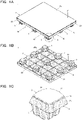
FIG. 1A is a perspective view mainly showing an top surface of a pallet according to an embodiment of the present invention,FIG. 1B is a perspective view mainly showing a bottom surface of the pallet, andFIG. 1C is a enlarged view of the region A inFIG. 1A . -
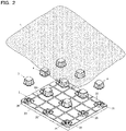
FIG. 2 is an exploded perspective view mainly showing the bottom surface of the pallet. -
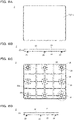
FIG. 3A is a plan view of the pallet,FIG. 3B is a side view, andFIG. 3C is a bottom view. -
FIG. 4A is an enlarged view of the region B inFIG. 3B , andFIG. 4B is the enlarged view of the region C inFIG. 3C . -
FIG. 5A is a perspective view mainly showing the top surface of a pallet body used in the pallet, andFIG. 5B is a perspective view mainly showing a bottom surface of the pallet body. -
FIG. 6A is a plan view of the pallet body,FIG. 6B is a front view,FIG. 6C is a bottom view, andFIG. 6D is a side view. -
FIG. 7A is an enlarged view of the region D inFIG. 6C , andFIG. 7B is a sectional view taken along the line E-E inFIG. 7A . -
FIG. 8A is a perspective view mainly showing the top surface of the leg used in the pallet,FIG. 8B is a perspective view mainly showing the bottom surface of the leg, andFIG. 8C is a bottom view of the leg,FIG. 8D is a side view,FIG. 8E is a plan view, andFIG. 8F is a side sectional view. -
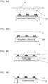
FIG. 9A to FIG. 9D are side views for explaining processes of a vacuum-forming of a resin sheet on the pallet. -
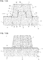
FIG. 10A is a partial cross-sectional view for explaining, in the vacuum-forming of the resin sheet, the function of exhaust holes made in the pallet body, andFIG. 10B is a partial side view. - A pallet according to an embodiment of the present invention will be described with reference to the drawings. As shown in
FIG. 1A to FIG. 1C ,FIG. 2 ,FIG. 3A to FIG. 3C andFIG. 4A and FIG. 4B , thepallet 1 of this embodiment can be preferably used for the management and transportation of goods using a forklift, a hand-drawn pallet jack or the like at a distribution site or the like. In the following description, the left front side of thepallet 1 shown inFIG. 1A is referred to as the front, and the right front side of thepallet 1 is referred to as the right side. - The
pallet 1 comprises a plate-like pallet body 2 made of foamed resin, a plurality oflegs 3 provided on the bottom surface of thepallet body 2, and aresin sheet 4 that covers the outer surfaces of thepallet body 2 and the legs 3 (seeFIG. 2 ). The plurality oflegs 3 are arranged in a lattice pattern at predetermined intervals on the bottom surface of thepallet body 2. In this example, ninelegs 3 of 3 × 3 are provided, each of which has a box-like shape with a substantially square projected area in plan view. In the illustrated example, theresin sheet 4 is shown in gray for convenience of explanation, but theresin sheet 4 may be transparent or the same white as thepallet body 2. - The
leg 3 is a support member that raises the height of thetop surface 21 serving as theloading surface 20, and the plurality oflegs 3 are arranged at predetermined intervals from theadjacent legs 3, thereby thefork insertion portion 10 into which a fork is inserted is formed (FIG. 1A ). In this example, the structure of thepallet 1 of so-called four-way insertion is shown, in which thefork insertion portion 10 is formed between thelegs 3 on both sides and thelegs 3 on center, and the fork insertion portions are opened on four sides, namely, left, right, front and back sides, thus four insertion directions are available. In addition, for example, legs each of which has a long box-like shape with a substantially rectangular projected area in plan view may be provided in a three-row arrangement, and so-called two-way insertion may be possible. - The
pallet body 2 and thelegs 3 are molded as separate parts. The material constituting thepallet body 2 is, for example, a foamed synthetic resin such as a polyolefin-based resin such as polystyrene, polyethylene, or polypropylene, and in the present embodiment, foamed polystyrene (EPS: expanded polystyrene) is used. The material constituting thelegs 3 is preferably the same as that of thepallet body 2, but a material different in density and hardness from thepallet body 2 may be used, or another material may be used. - As shown in
FIG. 4A and FIG. 4B , theresin sheet 4 covers thebottom surface 22 of thepallet body 2, thelegs 3, theside surface 23 of thepallet body 2, and a step portion described later. Since thelegs 3 are covered with theresin sheet 4 together with thebottom surface 22 of thepallet body 2, they are more firmly fixed to thepallet body 2. - As shown in
FIG. 5A and FIG. 5B andFIG. 6A and FIG. 6D , thepallet body 2 is a plate-like member having a predetermined thickness and having a rectangular shape in plan view. Thepallet body 2 of the present example is formed so that the width on the front side (FIG. 6B ) is slightly larger than the width on the side surface (FIG. 6D ), but this is not limitative, instead, the shape of thepallet body 2 may be appropriately selected from various shapes including a polygonal shape in plan view. Thepallet body 2 comprises thetop surface 21 having aloading surface 20 on which goods is loaded, thebottom surface 22 on which thelegs 3 are provided, and theside surface 23 connecting thetop surface 21 and thebottom surface 22. The outer dimensions of thetop surface 21 and thebottom surface 22 are substantially equal, and the corners made of the side surfaces 23 are chamfered so as to be rounded (see alsoFIG. 1C ). - On the
top surface 21 of thepallet body 2, thestep portion 24 is provided, which is formed in a shape down-step from the outer peripheral edge of theloading surface 20, on which the goods-conveyed is placed, to theside surface 23 of the pallet body 2 (seeFIG. 4A ). Thestep portion 24 is formed in a region having a width of about 1 to 15 mm from the outer peripheral edge (ridge line portion with the side surface 23) of thetop surface 21 toward the inside. When the width of thestep portion 24 is too large, theloading surface 20 becomes unnecessarily narrow, and when the width of thestep portion 24 is too small, theresin sheet 4 becomes insufficiently wound as described later. Further, the depth of the step portion 24 (step difference from the loading surface 20) is preferably 2 to 15 mm. If thestep portion 24 is too shallow, theresin sheet 4 may not accurately cover thestep portion 24, and if thestep portion 24 is too deep, surface strength will decrease, because exposed area of the foamed resin in the peripheral edge portion of theloading surface 20 increases. The ridge line portion between thestep portion 24 and theloading surface 20 is chamfered so as to be a curved surface (see alsoFIG. 7B ). - The surface of the
bottom surface 22 of thepallet body 2 is provided with thegrooves 22a formed in a lattice shape in order to prevent the inserted fork from slipping. Further, thebottom surface 22 of thepallet body 2 has thefitting concaves 25 in which thelegs 3 are fitted. Each of thefitting concaves 25 is formed so that its inner dimension is substantially equal to the outer dimension of the top surface (joint surface 31) of theleg 3. - As shown in
FIG. 7A , in the fitting concave 25 at the center thereof, the fitting convex 26 is formed, which is fitted with the fitting concave 34 formed on the top surface of the leg 3 (seeFIG. 8A and FIG. 8F ). The fitting convex 26 is a trapezoidal protrusion whose top portion is slightly smaller than the bottom portion, and thevertical grooves 27 are formed on the four side surfaces thereof, and also theventilation grooves 28 are formed on the bottom surface of the fitting concave 25 radially from the convex 26 at the center. In this example, theventilation grooves 28 are formed so as to extend in eight directions around the fitting convex 26. Further, thelongitudinal grooves 27 formed on the four side surfaces of the fitting convex 26 are connected to theventilation groove 28 on the bottom surface of the fitting concave 25. - Also, the plurality of exhaust holes 29 carved in the thickness direction of the pallet body are made on the bottom surface of the fitting concave 25. The exhaust holes 29 are provided at the outer periphery of the
ventilation grooves 28 at the periphery of the fitting concave 25. As shown inFIG. 7B , the exhaust holes 29 does not penetrate to thetop surface 21 of thepallet body 2, and a predetermined thickness is ensured from the bottom of the exhaust holes 29 to thetop surface 21 of thepallet body 2. The thickness is preferably 5 mm or more, and particularly preferably 5 to 15 mm, for example. However, for the vacuum-forming processing of theresin sheet 4 described later, the thickness is desirably 15 mm or less. - As shown in
FIG. 8A to FIG. 8F , theleg 3 includes thejoint surface 31 joined to thepallet body 2, theinstallation surface 32 serving as a bottom surface when thepallet 1 is placed, and theside surface 33 distributed between thejoint surface 31 and theinstallation surface 32. In theleg 3 of this embodiment, thejoint surface 31 and theinstallation surface 32 have a substantially rectangular shape in plan view, and theleg 3 has a block shape with four side surfaces 33. The fourside surfaces 33 have the same shape, and only one side surface is shown inFIG. 8D . - The
leg 3 is formed so that thejoint surface 31 is slightly larger than theinstallation surface 32, and theside surface 33 between them is slightly inclined. Thejoint surface 31 has theflange 31a that slightly extends outward. Theflange 31a is fitted into the fitting concave 25 of thepallet body 2, and thebottom surface 22 of thepallet body 2 and theside surface 33 of theleg 3 are connected to theflange 31a at a moderate angle. Moreover, theflange 31a has thethin part 31b with slightly thin thickness at the location where theflange 31a faces theventilation groove 28 in planar view. - The
joint surface 31 of theleg 3 is provided with the fitting concave 34 into which the fitting convex 26 of thepallet body 2 is fitted. The fitting concave 34 is formed so that its inner dimension is substantially equal to the outer dimension of the fitting convex 26 of thepallet body 2. The fitting concave 34 is formed so that its depth is deeper than the height of the fitting convex 26. In the bottom of the fitting concave 34, theround hole 34a is formed, and further theneedle hole 34b penetrating to theinstallation surface 32 of theleg 3 is formed in the bottom of theround hole 34a. Therefore, the fitting concave 34 communicates with the outside, namely, theinstallation surface 32 side of theleg 3 through theround hole 34a and theneedle hole 34b. Further, when theleg 3 is attached to thepallet body 2, the fitting concave 34 communicates also with the exhaust holes 29 through thevertical grooves 27 on the four side surfaces of the fitting convex 26 and theventilation grooves 28 on the bottom surface of the fitting concave 25. - The height of the
side surface 33 of theleg 3 is designed so that the raised amount of theloading surface 20 becomes a desired value. In addition, a plurality ofribs 33a are formed in theside surface 33 in the vertical direction to improve strength. It should be noted that on theinstallation surface 32 of theleg 3 except for the vicinity of theneedle hole 34b, a cover or the like (not shown) made of curable resin, wood, metal etc. may be attached in order to prevent the deterioration of the foamed polystyrene and the generation of debris due to a plurality of conveyances using a forklift. In addition, theleg 3 is not limited to the illustrated shape, and may be, for example, an elliptical column shape or a polygonal column shape other than such a quadrangular column. - The
resin sheet 4 is a sheet member that is softened and deformed by heating, cured at room temperature, and has sufficient strength and surface durability against a heavy object placed thereon. As the material of theresin sheet 4 of the present embodiment, a resin material made of the same compound as thepallet body 2 is preferably used. When thepallet body 2 and thelegs 3 are made of the above-mentioned expanded polystyrene, for example, a high-impact polystyrene (HIPS) sheet is used as theresin sheet 4. - In the
pallet 1 of this embodiment, the procedure, for integrally forming theresin sheet 4 on thepallet body 2, will be described with reference toFIG. 9 andFIG. 10 . First, as shown inFIG. 9A , apallet body 2 molded into a predetermined shape is prepared. Thepallet body 2 is provided withlegs 3. Next, thepallet body 2 is placed on the top surface of thevacuum chamber 51 so that thebottom surface 22 with thelegs 3 faces upward and thetop surface 21 having theloading surface 20 faces downward, and then theresin sheet 4 is placed thereon. Theheater 52 is disposed above theresin sheet 4, and theheater 52 heats theresin sheet 4 to soften theresin sheet 4. - The
vacuum chamber 51 is movable upward with thepallet body 2 placed thereon. As shown inFIG. 9B and FIG. 9C , when theresin sheet 4 is softened, theheater 52 is retracted and the vacuum chamber 51 (upper table) is pulled up to bring thepallet body 2 and theresin sheet 4 into contact. Thevacuum chamber 51 is provided with suction ports (not shown) communicating between the internal space of thevacuum chamber 51 and the outside on the top surface side of thevacuum chamber 51, and a vacuum pump for decompressing the internal space. When thevacuum chamber 51 brings thepallet body 2 into close contact with the softenedresin sheet 4, the vacuum pump is operated, as shown inFIG. 9D , to evacuate the air between thepallet body 2 and theresin sheet 4, and theresin sheet 4 is vacuum-adsorbed to thepallet body 2. - As shown in
FIG. 10A , thepallet body 2 is provided with the exhaust holes 29. The exhaust holes 29 can communicate with the fitting concave 34 of theleg 3 through theventilation grooves 28 and thevertical grooves 27, and the fitting concave 34 is connected to the outside of theinstallation surface 32 of theleg 3 through theround hole 34a and theneedle hole 34b. Although theexhaust hole 29 does not penetrate thetop surface 21 of thepallet body 2, theexhaust hole 29 can effectively communicate with the outside of thetop surface 21 of thepallet body 2 through slight gaps between the foamed beads because the thickness of that portion is thin. Therefore, when thevacuum chamber 51 is operated to evacuate air from thetop surface 21 side of thepallet body 2 so as to decompress, the air between thetop surface 21 of thepallet body 2 and thelegs 3 and theresin sheet 4 placed thereon is evacuated through theneedle hole 34b, theround hole 34a, the fitting concave 34, thevertical grooves 27, theventilation grooves 28, and the exhaust holes 29. Also, since thethin portion 31b of theflange 31a of theleg 3 is thin, the air between thepallet body 2 and theresin sheet 4 is exhausted through this thin portion, theventilation grooves 28, and theexhaust hole 29. - Thereby, the
top surface 21, theside surface 23, and the outer surface of thelegs 3 of thepallet body 2 are covered with theresin sheet 4 without any gap. Further, theresin sheet 4 is not coated on theloading surface 20, which is in contact with the upper table of thevacuum chamber 51, however since thestep portion 24 is slightly separated with space from the upper table of thevacuum chamber 51, theresin sheet 4 can enter the space and thestep portion 24 is also covered with theresin sheet 4. - Subsequently, the operation of the
vacuum chamber 51 is stopped, thepallet body 2 and others are returned to atmospheric pressure, and thepallet 1 covered with theresin sheet 4 is removed from the top thevacuum chamber 51. At this time, as shown inFIG. 10B , the portion of theresin sheet 4 covering thestep portion 24 is stretched, and the sheet thickness of that portion is reduced. Finally, a knife or the like is inserted into the gap between thestep portion 24 and theloading surface 20, and the remainingresin sheet 4 is trimmed. In this trimming, since the sheet thickness of theresin sheet 4 where the knife is inserted is thin, trimming can be easily performed. Moreover, since the ridge line part between thestep portion 24 and theloading surface 20 is chamfered so as to be a curved surface, it is easy to insert a knife. Thus, apallet 1 can be obtained, in which thebottom surface 22 of thepallet body 2, the outer surface of theleg 3, theside surface 23 and thestep portion 24 of thepallet body 2 are covered with theresin sheet 4, and theloading surface 20 is not covered with theresin sheet 4. - In the
pallet 1 configured as described above, since thepallet body 2 constituting the main body is made of foamed resin, it is lightweight, and since theresin sheet 4 is integrally formed on the bottom surface side of thepallet 1 by vacuum-forming, compared with the foamed resin constituting themain body 2, more surface durability can be obtained. Particularly, following surfaces are vulnerable to damage: the surface, among thebottom surface 22 of thepallet body 2, located between thelegs 3 into which a fork is inserted; theinstallation surface 32 of thelegs 3, which is placed on a hard installation place such as concrete or asphalt; and theside surface 23 of thepallet body 2 having many opportunities to come into contact with walls and other structures. However, since those surfaces are covered with theresin sheet 4 in thepallet 1, theresin sheet 4 can reduce the damage of those places and ensure the strength of the outer surface. - Further, the
pallet 1 is covered with theresin sheet 4 up to thestep portion 24 on thetop surface 21 side of thepallet body 2. That is, theresin sheet 4 is wound up to the part of thetop surface 21 of thepallet body 2, and therefore, for example, as compared with the case where theresin sheet 4 covers only thebottom surface 22 of thepallet body 2 and thelegs 3 or at most up to theside surface 23 of thepallet body 2, theresin sheet 4 is hardly peeled off and the durability of thepallet 1 can be improved. Furthermore, since theresin sheet 4 covers only up to thestep portion 24 step-downed from theloading surface 20, as the results, for example, the goods-conveyed placed on theloading surface 20 are prevented from coming into contact with the edge of theresin sheet 4, and so the peeling of theresin sheet 4 can be further effectively prevented. - As a matter of fact, the
resin sheet 4 has higher thermal conductivity than the foamed beads, and therefore heat is easily transferred to the goods-conveyed directly contacting with theresin sheet 4. Therefore, if both thetop surface 21 and thebottom surface 22 of thepallet body 2 are covered with the resin sheet 4 (in the case of a so-called full-laminated type), compared to those not covered with theresin sheet 4, there is a possibility that the advantageous function such as thermal insulation performance and cushioning property inherent to the foamed resin cannot be fully exhibited. On the other hand, in thepallet 1 of this embodiment, theloading surface 20 is not covered with theresin sheet 4, so thepallet 1 is of half-laminated type, and theloading surface 20 is an exposed surface of the foamed resin (made of foamed beads) which has thermal insulation performance and cushioning property and forms thepallet body 2. Therefore, thepallet 1 can ensure high thermal insulation performance that makes it difficult for heat from the road surface or the warehouse floor, etc. to be transferred to the goods-conveyed placed on thepallet 1, and the cushioning property unique to the foamed resin can ensure protection for the goods-conveyed against heat and shock during conveyance. Therefore, it is possible to obtain thepallet 1 having excellent thermal insulation performance and cushioning property with respect to the placed goods-conveyed while ensuring the strength of the outer surface of the pallet. - Further, since the
pallet 1 is provided withexhaust holes 29 at the positions where thelegs 3 are arranged on thebottom surface 22 of thepallet body 2, after theresin sheet 4 is formed for covering, the exhaust holes 29 can be hidden. Moreover, since the exhaust holes 29 are provided at the peripheral edge of the fitting concave 25, the decompressing effect around theflange 31a of theleg 3 becomes high, and theresin sheet 4 is more strongly stuck thereto, and thelegs 3 and thepallet body 2 can be more firmly fixed. Furthermore, since the exhaust holes 29 do not penetrate to thetop surface 21 of thepallet body 2, any large concave is not formed on theloading surface 20, and damage to theloading surface 20 can be suppressed. - It should be noted that the present invention is not limited to the configuration of the above embodiment, and various modifications can be made without departing from the spirit of the invention. Moreover, in the above described embodiment, although the structure of the
pallet 1 applies to the example of the conveyance of the goods using the forklift, it is not excluded to apply to another structure made of foamed synthetic resin. Moreover, in the above described embodiment, although thepallet 1 shown is one suitably used with a forklift, however, for example, a pallet of floor-standing type or self-moving type with casters on the bottom surface of thepallet body 2 may be included. -
- 1
- Pallet
- 2
- Pallet body
- 20
- Loading surface
- 21
- Top surface
- 22
- Bottom surface
- 23
- Side surface
- 24
- Step portion
- 25
- Fitting concave
- 29
- Exhaust hole
- 3
- Leg
- 4
- Resin sheet
Claims (7)
- A pallet comprising:a plate-like pallet body made of foamed resin;a plurality of legs provided on a bottom surface of the pallet body; anda resin sheet integrated by vacuum-forming from the bottom surface side of the pallet, whereina top surface of the pallet body has a loading surface on which goods-conveyed is placed, and a step portion formed in a shape down-step from the outer peripheral edge of the loading surface to the side surface of the pallet body, andthe resin sheet covers the bottom surface of the pallet body, the legs, the side surfaces of the pallet body and the step portion, and the loading surface is not covered with the resin sheet.
- The pallet according to claim 1, wherein
the resin sheet has a thin sheet thickness at a portion covering the step portion. - The pallet according to claim 1 or 2, whereinthe pallet body and the legs are molded as separate bodies, andthe bottom surface of the pallet body has an exhaust hole made in a thickness direction of the pallet body at a place where the leg is arranged.
- The pallet according to claim 3, whereinthe bottom surface of the pallet body has a fitting concave into which the leg is fitted, andthe exhaust hole is provided at a peripheral edge of the fitting concave.
- The pallet according to claim 3 or 4, whereinthe exhaust hole does not penetrate to the top surface of the pallet body, anda thickness of 5 mm or more is provided from a bottom of the exhaust hole to the top surface of the pallet body.
- The pallet according to any one of claims 1 to 5, wherein
a ridge line portion between the step portion and the loading surface is chamfered to be a curved surface. - The pallet according to any one of claims 1 to 6, wherein
the loading surface is an exposed surface of the foamed resin forming the pallet body and having a thermal insulation performance and a cushioning property.
Applications Claiming Priority (1)
| Application Number | Priority Date | Filing Date | Title |
|---|---|---|---|
| PCT/JP2019/035940 WO2021048979A1 (en) | 2019-09-12 | 2019-09-12 | Pallet |
Publications (4)
| Publication Number | Publication Date |
|---|---|
| EP4030227A1 true EP4030227A1 (en) | 2022-07-20 |
| EP4030227A4 EP4030227A4 (en) | 2022-09-14 |
| EP4030227C0 EP4030227C0 (en) | 2025-07-09 |
| EP4030227B1 EP4030227B1 (en) | 2025-07-09 |
Family
ID=69998032
Family Applications (1)
| Application Number | Title | Priority Date | Filing Date |
|---|---|---|---|
| EP19919565.2A Active EP4030227B1 (en) | 2019-09-12 | 2019-09-12 | Pallet |
Country Status (7)
| Country | Link |
|---|---|
| US (1) | US11305912B2 (en) |
| EP (1) | EP4030227B1 (en) |
| JP (1) | JP6660516B1 (en) |
| CN (1) | CN112867676B (en) |
| SG (1) | SG11202011301PA (en) |
| TW (1) | TWI740597B (en) |
| WO (1) | WO2021048979A1 (en) |
Families Citing this family (2)
| Publication number | Priority date | Publication date | Assignee | Title |
|---|---|---|---|---|
| CN108899453B (en) * | 2018-07-19 | 2022-09-02 | 上海赛科利汽车模具技术应用有限公司 | Battery tray bottom plate structure and preparation method thereof |
| US11603228B2 (en) * | 2019-10-10 | 2023-03-14 | P.R.A. Company | Reusable recyclable thermoformed shipping containers |
Family Cites Families (21)
| Publication number | Priority date | Publication date | Assignee | Title |
|---|---|---|---|---|
| US3581681A (en) * | 1969-03-10 | 1971-06-01 | Irving M Newton | Pallet |
| JPS575310Y2 (en) * | 1977-02-10 | 1982-02-01 | ||
| JPS5996128U (en) * | 1982-12-20 | 1984-06-29 | 三井東圧化学株式会社 | palette |
| JP2000168777A (en) * | 1998-12-02 | 2000-06-20 | Mitsubishi Rayon Co Ltd | palette |
| JP2003072754A (en) | 2001-09-04 | 2003-03-12 | Sekisui Plastics Co Ltd | Pallet integrated molding container and method of manufacturing the same |
| US6655299B2 (en) * | 2001-10-30 | 2003-12-02 | Patent Holding Company | Reinforced composite pallet assembly of the cellular core sandwich-type |
| US6997113B1 (en) * | 2003-10-14 | 2006-02-14 | The Fabri-Form Company | Pallet |
| US7413698B2 (en) * | 2004-06-01 | 2008-08-19 | Novo Foam Products Llc | Method of molding load-bearing articles from compressible cores and heat malleable coverings |
| JP2007176534A (en) | 2005-12-27 | 2007-07-12 | Sekisui Plastics Co Ltd | Resin pallet |
| JP2007176533A (en) * | 2005-12-27 | 2007-07-12 | Sekisui Plastics Co Ltd | Resin pallet and manufacturing method thereof |
| AT505421B1 (en) * | 2007-07-10 | 2010-07-15 | Hirsch Maschb Gmbh | PLATE-type ELEMENT FOR SUPPORTING BZW. CARRYING A SUBJECT AND METHOD FOR THE PRODUCTION THEREOF |
| KR100985998B1 (en) * | 2009-09-29 | 2010-10-06 | 백대현 | Lightweight pallet |
| CN102910343B (en) * | 2012-11-06 | 2014-12-17 | 苏州金柏包装科技发展有限公司 | Compound cored polyfoam pallet and manufacturing technology thereof |
| CN103708082A (en) * | 2013-12-30 | 2014-04-09 | 翡柯机械(福建)有限公司 | Production technology and production equipment for light tray |
| CN105197344A (en) * | 2014-06-25 | 2015-12-30 | 艾尔戴克斯国际公司 | Load bearing structure |
| CN204323872U (en) * | 2014-11-27 | 2015-05-13 | 莱斯维克私人有限公司 | For the liner plate platform of bearing goods |
| CN105197345B (en) * | 2015-09-22 | 2017-10-24 | 苏州金柏包装科技发展有限公司 | A kind of composite band muscle expanded polystyrene (EPS) pallet and its manufacture method |
| EP3208066A1 (en) * | 2016-02-17 | 2017-08-23 | NGP Next Generation Pallets GmbH | Method and manufacturing device for manufacturing a laminated object, laminated objects, method for producing pallets, and pallets |
| US10266303B1 (en) * | 2016-09-06 | 2019-04-23 | Charles D. Kownacki | Light-weight structural panel construction |
| CN208233604U (en) * | 2018-04-24 | 2018-12-14 | 广州市湘福包装制品有限公司 | A kind of anti abrasive EPO foam transfer pallet of scratch resistance |
| CN208915694U (en) * | 2018-08-10 | 2019-05-31 | 广东奔迪新材料科技有限公司 | a lightweight pallet |
-
2019
- 2019-09-12 JP JP2019554571A patent/JP6660516B1/en active Active
- 2019-09-12 SG SG11202011301PA patent/SG11202011301PA/en unknown
- 2019-09-12 CN CN201980004143.0A patent/CN112867676B/en active Active
- 2019-09-12 US US16/630,590 patent/US11305912B2/en active Active
- 2019-09-12 EP EP19919565.2A patent/EP4030227B1/en active Active
- 2019-09-12 WO PCT/JP2019/035940 patent/WO2021048979A1/en not_active Ceased
-
2020
- 2020-08-07 TW TW109126767A patent/TWI740597B/en active
Also Published As
| Publication number | Publication date |
|---|---|
| JPWO2021048979A1 (en) | 2021-09-30 |
| CN112867676B (en) | 2022-09-16 |
| SG11202011301PA (en) | 2021-04-29 |
| EP4030227C0 (en) | 2025-07-09 |
| JP6660516B1 (en) | 2020-03-11 |
| TW202110717A (en) | 2021-03-16 |
| EP4030227A4 (en) | 2022-09-14 |
| WO2021048979A1 (en) | 2021-03-18 |
| EP4030227B1 (en) | 2025-07-09 |
| TWI740597B (en) | 2021-09-21 |
| US11305912B2 (en) | 2022-04-19 |
| US20210403200A1 (en) | 2021-12-30 |
| CN112867676A (en) | 2021-05-28 |
Similar Documents
| Publication | Publication Date | Title |
|---|---|---|
| US3404642A (en) | Pallet | |
| US6607199B2 (en) | Tray and dolly assembly | |
| JP2021524829A (en) | Repairable plastic pallets with carving on the top deck and related methods | |
| US11560256B2 (en) | Roto molded pallet | |
| US11305912B2 (en) | Pallet | |
| US20070209557A1 (en) | Pallet with stepped support blocks and related methods | |
| US7878127B2 (en) | Pallet with optimized cargo layer and related methods | |
| US12540006B2 (en) | Pallet and manufacturing method thereof | |
| HK1244765B (en) | Cargo handling pallet | |
| HK40048195A (en) | Pallet | |
| HK40048195B (en) | Pallet | |
| JP7041507B2 (en) | palette | |
| HK40048197B (en) | Pallet and method for manufacturing same | |
| JP3954839B2 (en) | Carrying pallet | |
| JP7793187B2 (en) | Loading equipment | |
| JP3248519U (en) | palette | |
| KR200412873Y1 (en) | Paper pallets | |
| US20260091910A1 (en) | Stackable pallet | |
| JP3663464B2 (en) | Container pallet and sleeve | |
| JP2026068914A (en) | palette | |
| JP2003063532A (en) | Pallets and containers for cargo handling and transportation | |
| KR200413841Y1 (en) | Paper pallets | |
| JPH05319434A (en) | Synthetic resin transportation pallet | |
| JP2006076605A (en) | Pallet for transportation | |
| JPH09216627A (en) | palette |
Legal Events
| Date | Code | Title | Description |
|---|---|---|---|
| STAA | Information on the status of an ep patent application or granted ep patent |
Free format text: STATUS: UNKNOWN |
|
| STAA | Information on the status of an ep patent application or granted ep patent |
Free format text: STATUS: THE INTERNATIONAL PUBLICATION HAS BEEN MADE |
|
| PUAI | Public reference made under article 153(3) epc to a published international application that has entered the european phase |
Free format text: ORIGINAL CODE: 0009012 |
|
| STAA | Information on the status of an ep patent application or granted ep patent |
Free format text: STATUS: REQUEST FOR EXAMINATION WAS MADE |
|
| 17P | Request for examination filed |
Effective date: 20200925 |
|
| AK | Designated contracting states |
Kind code of ref document: A1 Designated state(s): AL AT BE BG CH CY CZ DE DK EE ES FI FR GB GR HR HU IE IS IT LI LT LU LV MC MK MT NL NO PL PT RO RS SE SI SK SM TR |
|
| REG | Reference to a national code |
Ref country code: DE Ref legal event code: R079 Ipc: B65D0019320000 Ref country code: DE Ref legal event code: R079 Ref document number: 602019072476 Country of ref document: DE Free format text: PREVIOUS MAIN CLASS: G02F0001133900 Ipc: B65D0019320000 |
|
| A4 | Supplementary search report drawn up and despatched |
Effective date: 20220812 |
|
| RIC1 | Information provided on ipc code assigned before grant |
Ipc: B29C 51/36 20060101ALI20220808BHEP Ipc: B65D 19/32 20060101AFI20220808BHEP |
|
| DAV | Request for validation of the european patent (deleted) | ||
| DAX | Request for extension of the european patent (deleted) | ||
| GRAP | Despatch of communication of intention to grant a patent |
Free format text: ORIGINAL CODE: EPIDOSNIGR1 |
|
| STAA | Information on the status of an ep patent application or granted ep patent |
Free format text: STATUS: GRANT OF PATENT IS INTENDED |
|
| INTG | Intention to grant announced |
Effective date: 20250206 |
|
| GRAS | Grant fee paid |
Free format text: ORIGINAL CODE: EPIDOSNIGR3 |
|
| GRAA | (expected) grant |
Free format text: ORIGINAL CODE: 0009210 |
|
| STAA | Information on the status of an ep patent application or granted ep patent |
Free format text: STATUS: THE PATENT HAS BEEN GRANTED |
|
| AK | Designated contracting states |
Kind code of ref document: B1 Designated state(s): AL AT BE BG CH CY CZ DE DK EE ES FI FR GB GR HR HU IE IS IT LI LT LU LV MC MK MT NL NO PL PT RO RS SE SI SK SM TR |
|
| REG | Reference to a national code |
Ref country code: GB Ref legal event code: FG4D |
|
| REG | Reference to a national code |
Ref country code: CH Ref legal event code: EP |
|
| REG | Reference to a national code |
Ref country code: IE Ref legal event code: FG4D |
|
| REG | Reference to a national code |
Ref country code: DE Ref legal event code: R096 Ref document number: 602019072476 Country of ref document: DE |
|
| U01 | Request for unitary effect filed |
Effective date: 20250808 |
|
| U07 | Unitary effect registered |
Designated state(s): AT BE BG DE DK EE FI FR IT LT LU LV MT NL PT RO SE SI Effective date: 20250820 |
|
| U20 | Renewal fee for the european patent with unitary effect paid |
Year of fee payment: 7 Effective date: 20251002 |
|
| PG25 | Lapsed in a contracting state [announced via postgrant information from national office to epo] |
Ref country code: IS Free format text: LAPSE BECAUSE OF FAILURE TO SUBMIT A TRANSLATION OF THE DESCRIPTION OR TO PAY THE FEE WITHIN THE PRESCRIBED TIME-LIMIT Effective date: 20251109 |
|
| PGFP | Annual fee paid to national office [announced via postgrant information from national office to epo] |
Ref country code: GB Payment date: 20251203 Year of fee payment: 7 |
|
| PG25 | Lapsed in a contracting state [announced via postgrant information from national office to epo] |
Ref country code: NO Free format text: LAPSE BECAUSE OF FAILURE TO SUBMIT A TRANSLATION OF THE DESCRIPTION OR TO PAY THE FEE WITHIN THE PRESCRIBED TIME-LIMIT Effective date: 20251009 |
|
| PG25 | Lapsed in a contracting state [announced via postgrant information from national office to epo] |
Ref country code: HR Free format text: LAPSE BECAUSE OF FAILURE TO SUBMIT A TRANSLATION OF THE DESCRIPTION OR TO PAY THE FEE WITHIN THE PRESCRIBED TIME-LIMIT Effective date: 20250709 |
|
| PG25 | Lapsed in a contracting state [announced via postgrant information from national office to epo] |
Ref country code: GR Free format text: LAPSE BECAUSE OF FAILURE TO SUBMIT A TRANSLATION OF THE DESCRIPTION OR TO PAY THE FEE WITHIN THE PRESCRIBED TIME-LIMIT Effective date: 20251010 |
|
| PG25 | Lapsed in a contracting state [announced via postgrant information from national office to epo] |
Ref country code: PL Free format text: LAPSE BECAUSE OF FAILURE TO SUBMIT A TRANSLATION OF THE DESCRIPTION OR TO PAY THE FEE WITHIN THE PRESCRIBED TIME-LIMIT Effective date: 20250709 |
|
| PG25 | Lapsed in a contracting state [announced via postgrant information from national office to epo] |
Ref country code: RS Free format text: LAPSE BECAUSE OF FAILURE TO SUBMIT A TRANSLATION OF THE DESCRIPTION OR TO PAY THE FEE WITHIN THE PRESCRIBED TIME-LIMIT Effective date: 20251009 |
|
| PG25 | Lapsed in a contracting state [announced via postgrant information from national office to epo] |
Ref country code: ES Free format text: LAPSE BECAUSE OF FAILURE TO SUBMIT A TRANSLATION OF THE DESCRIPTION OR TO PAY THE FEE WITHIN THE PRESCRIBED TIME-LIMIT Effective date: 20250709 |
|
| PG25 | Lapsed in a contracting state [announced via postgrant information from national office to epo] |
Ref country code: SM Free format text: LAPSE BECAUSE OF FAILURE TO SUBMIT A TRANSLATION OF THE DESCRIPTION OR TO PAY THE FEE WITHIN THE PRESCRIBED TIME-LIMIT Effective date: 20250709 |
|
| PG25 | Lapsed in a contracting state [announced via postgrant information from national office to epo] |
Ref country code: CZ Free format text: LAPSE BECAUSE OF FAILURE TO SUBMIT A TRANSLATION OF THE DESCRIPTION OR TO PAY THE FEE WITHIN THE PRESCRIBED TIME-LIMIT Effective date: 20250709 |
|
| PG25 | Lapsed in a contracting state [announced via postgrant information from national office to epo] |
Ref country code: SK Free format text: LAPSE BECAUSE OF FAILURE TO SUBMIT A TRANSLATION OF THE DESCRIPTION OR TO PAY THE FEE WITHIN THE PRESCRIBED TIME-LIMIT Effective date: 20250709 |
|
| U1N | Appointed representative for the unitary patent procedure changed after the registration of the unitary effect |
Representative=s name: MARKS & CLERK LLP; GB |
|
| REG | Reference to a national code |
Ref country code: CH Ref legal event code: H13 Free format text: ST27 STATUS EVENT CODE: U-0-0-H10-H13 (AS PROVIDED BY THE NATIONAL OFFICE) Effective date: 20260504 |
|
| PLBE | No opposition filed within time limit |
Free format text: ORIGINAL CODE: 0009261 |
|
| STAA | Information on the status of an ep patent application or granted ep patent |
Free format text: STATUS: NO OPPOSITION FILED WITHIN TIME LIMIT |
|
| REG | Reference to a national code |
Ref country code: CH Ref legal event code: L10 Free format text: ST27 STATUS EVENT CODE: U-0-0-L10-L00 (AS PROVIDED BY THE NATIONAL OFFICE) Effective date: 20260521 |
|
| 26N | No opposition filed |
Effective date: 20260410 |
|
| PG25 | Lapsed in a contracting state [announced via postgrant information from national office to epo] |
Ref country code: MC Free format text: LAPSE BECAUSE OF FAILURE TO SUBMIT A TRANSLATION OF THE DESCRIPTION OR TO PAY THE FEE WITHIN THE PRESCRIBED TIME-LIMIT Effective date: 20250709 |
|
| PG25 | Lapsed in a contracting state [announced via postgrant information from national office to epo] |
Ref country code: CH Free format text: LAPSE BECAUSE OF NON-PAYMENT OF DUE FEES Effective date: 20250930 Ref country code: IE Free format text: LAPSE BECAUSE OF NON-PAYMENT OF DUE FEES Effective date: 20250912 |