EP4030132A1 - Heat exchanger fin, heat exchanger, indoor unit and air conditioner - Google Patents
Heat exchanger fin, heat exchanger, indoor unit and air conditioner Download PDFInfo
- Publication number
- EP4030132A1 EP4030132A1 EP20880266.0A EP20880266A EP4030132A1 EP 4030132 A1 EP4030132 A1 EP 4030132A1 EP 20880266 A EP20880266 A EP 20880266A EP 4030132 A1 EP4030132 A1 EP 4030132A1
- Authority
- EP
- European Patent Office
- Prior art keywords
- contour line
- heat exchanger
- fin body
- air inlet
- fin
- Prior art date
- Legal status (The legal status is an assumption and is not a legal conclusion. Google has not performed a legal analysis and makes no representation as to the accuracy of the status listed.)
- Granted
Links
Images



Classifications
-
- F—MECHANICAL ENGINEERING; LIGHTING; HEATING; WEAPONS; BLASTING
- F28—HEAT EXCHANGE IN GENERAL
- F28F—DETAILS OF HEAT-EXCHANGE AND HEAT-TRANSFER APPARATUS, OF GENERAL APPLICATION
- F28F1/00—Tubular elements; Assemblies of tubular elements
- F28F1/10—Tubular elements and assemblies thereof with means for increasing heat-transfer area, e.g. with fins, with projections, with recesses
- F28F1/12—Tubular elements and assemblies thereof with means for increasing heat-transfer area, e.g. with fins, with projections, with recesses the means being only outside the tubular element
- F28F1/24—Tubular elements and assemblies thereof with means for increasing heat-transfer area, e.g. with fins, with projections, with recesses the means being only outside the tubular element and extending transversely
- F28F1/32—Tubular elements and assemblies thereof with means for increasing heat-transfer area, e.g. with fins, with projections, with recesses the means being only outside the tubular element and extending transversely the means having portions engaging further tubular elements
- F28F1/325—Fins with openings
-
- F—MECHANICAL ENGINEERING; LIGHTING; HEATING; WEAPONS; BLASTING
- F24—HEATING; RANGES; VENTILATING
- F24F—AIR-CONDITIONING; AIR-HUMIDIFICATION; VENTILATION; USE OF AIR CURRENTS FOR SCREENING
- F24F1/00—Room units for air-conditioning, e.g. separate or self-contained units or units receiving primary air from a central station
- F24F1/0007—Indoor units, e.g. fan coil units
- F24F1/0059—Indoor units, e.g. fan coil units characterised by heat exchangers
- F24F1/0067—Indoor units, e.g. fan coil units characterised by heat exchangers by the shape of the heat exchangers or of parts thereof, e.g. of their fins
-
- F—MECHANICAL ENGINEERING; LIGHTING; HEATING; WEAPONS; BLASTING
- F28—HEAT EXCHANGE IN GENERAL
- F28F—DETAILS OF HEAT-EXCHANGE AND HEAT-TRANSFER APPARATUS, OF GENERAL APPLICATION
- F28F1/00—Tubular elements; Assemblies of tubular elements
- F28F1/10—Tubular elements and assemblies thereof with means for increasing heat-transfer area, e.g. with fins, with projections, with recesses
- F28F1/12—Tubular elements and assemblies thereof with means for increasing heat-transfer area, e.g. with fins, with projections, with recesses the means being only outside the tubular element
- F28F1/14—Tubular elements and assemblies thereof with means for increasing heat-transfer area, e.g. with fins, with projections, with recesses the means being only outside the tubular element and extending longitudinally
- F28F1/20—Tubular elements and assemblies thereof with means for increasing heat-transfer area, e.g. with fins, with projections, with recesses the means being only outside the tubular element and extending longitudinally the means being attachable to the element
-
- F—MECHANICAL ENGINEERING; LIGHTING; HEATING; WEAPONS; BLASTING
- F28—HEAT EXCHANGE IN GENERAL
- F28F—DETAILS OF HEAT-EXCHANGE AND HEAT-TRANSFER APPARATUS, OF GENERAL APPLICATION
- F28F1/00—Tubular elements; Assemblies of tubular elements
- F28F1/10—Tubular elements and assemblies thereof with means for increasing heat-transfer area, e.g. with fins, with projections, with recesses
- F28F1/12—Tubular elements and assemblies thereof with means for increasing heat-transfer area, e.g. with fins, with projections, with recesses the means being only outside the tubular element
- F28F1/24—Tubular elements and assemblies thereof with means for increasing heat-transfer area, e.g. with fins, with projections, with recesses the means being only outside the tubular element and extending transversely
- F28F1/32—Tubular elements and assemblies thereof with means for increasing heat-transfer area, e.g. with fins, with projections, with recesses the means being only outside the tubular element and extending transversely the means having portions engaging further tubular elements
-
- F—MECHANICAL ENGINEERING; LIGHTING; HEATING; WEAPONS; BLASTING
- F28—HEAT EXCHANGE IN GENERAL
- F28F—DETAILS OF HEAT-EXCHANGE AND HEAT-TRANSFER APPARATUS, OF GENERAL APPLICATION
- F28F13/00—Arrangements for modifying heat-transfer, e.g. increasing, decreasing
- F28F13/06—Arrangements for modifying heat-transfer, e.g. increasing, decreasing by affecting the pattern of flow of the heat-exchange media
- F28F13/08—Arrangements for modifying heat-transfer, e.g. increasing, decreasing by affecting the pattern of flow of the heat-exchange media by varying the cross-section of the flow channels
-
- F—MECHANICAL ENGINEERING; LIGHTING; HEATING; WEAPONS; BLASTING
- F24—HEATING; RANGES; VENTILATING
- F24F—AIR-CONDITIONING; AIR-HUMIDIFICATION; VENTILATION; USE OF AIR CURRENTS FOR SCREENING
- F24F13/00—Details common to, or for air-conditioning, air-humidification, ventilation or use of air currents for screening
- F24F13/30—Arrangement or mounting of heat-exchangers
-
- F—MECHANICAL ENGINEERING; LIGHTING; HEATING; WEAPONS; BLASTING
- F28—HEAT EXCHANGE IN GENERAL
- F28D—HEAT-EXCHANGE APPARATUS, NOT PROVIDED FOR IN ANOTHER SUBCLASS, IN WHICH THE HEAT-EXCHANGE MEDIA DO NOT COME INTO DIRECT CONTACT
- F28D1/00—Heat-exchange apparatus having stationary conduit assemblies for one heat-exchange medium only, the media being in contact with different sides of the conduit wall, in which the other heat-exchange medium is a large body of fluid, e.g. domestic or motor car radiators
- F28D1/02—Heat-exchange apparatus having stationary conduit assemblies for one heat-exchange medium only, the media being in contact with different sides of the conduit wall, in which the other heat-exchange medium is a large body of fluid, e.g. domestic or motor car radiators with heat-exchange conduits immersed in the body of fluid
- F28D1/0233—Heat-exchange apparatus having stationary conduit assemblies for one heat-exchange medium only, the media being in contact with different sides of the conduit wall, in which the other heat-exchange medium is a large body of fluid, e.g. domestic or motor car radiators with heat-exchange conduits immersed in the body of fluid with air flow channels
- F28D1/024—Heat-exchange apparatus having stationary conduit assemblies for one heat-exchange medium only, the media being in contact with different sides of the conduit wall, in which the other heat-exchange medium is a large body of fluid, e.g. domestic or motor car radiators with heat-exchange conduits immersed in the body of fluid with air flow channels with an air driving element
-
- F—MECHANICAL ENGINEERING; LIGHTING; HEATING; WEAPONS; BLASTING
- F28—HEAT EXCHANGE IN GENERAL
- F28D—HEAT-EXCHANGE APPARATUS, NOT PROVIDED FOR IN ANOTHER SUBCLASS, IN WHICH THE HEAT-EXCHANGE MEDIA DO NOT COME INTO DIRECT CONTACT
- F28D1/00—Heat-exchange apparatus having stationary conduit assemblies for one heat-exchange medium only, the media being in contact with different sides of the conduit wall, in which the other heat-exchange medium is a large body of fluid, e.g. domestic or motor car radiators
- F28D1/02—Heat-exchange apparatus having stationary conduit assemblies for one heat-exchange medium only, the media being in contact with different sides of the conduit wall, in which the other heat-exchange medium is a large body of fluid, e.g. domestic or motor car radiators with heat-exchange conduits immersed in the body of fluid
- F28D1/04—Heat-exchange apparatus having stationary conduit assemblies for one heat-exchange medium only, the media being in contact with different sides of the conduit wall, in which the other heat-exchange medium is a large body of fluid, e.g. domestic or motor car radiators with heat-exchange conduits immersed in the body of fluid with tubular conduits
- F28D1/053—Heat-exchange apparatus having stationary conduit assemblies for one heat-exchange medium only, the media being in contact with different sides of the conduit wall, in which the other heat-exchange medium is a large body of fluid, e.g. domestic or motor car radiators with heat-exchange conduits immersed in the body of fluid with tubular conduits the conduits being straight
- F28D1/05316—Assemblies of conduits connected to common headers, e.g. core type radiators
-
- F—MECHANICAL ENGINEERING; LIGHTING; HEATING; WEAPONS; BLASTING
- F28—HEAT EXCHANGE IN GENERAL
- F28F—DETAILS OF HEAT-EXCHANGE AND HEAT-TRANSFER APPARATUS, OF GENERAL APPLICATION
- F28F2210/00—Heat exchange conduits
- F28F2210/08—Assemblies of conduits having different features
-
- F—MECHANICAL ENGINEERING; LIGHTING; HEATING; WEAPONS; BLASTING
- F28—HEAT EXCHANGE IN GENERAL
- F28F—DETAILS OF HEAT-EXCHANGE AND HEAT-TRANSFER APPARATUS, OF GENERAL APPLICATION
- F28F2210/00—Heat exchange conduits
- F28F2210/10—Particular layout, e.g. for uniform temperature distribution
-
- F—MECHANICAL ENGINEERING; LIGHTING; HEATING; WEAPONS; BLASTING
- F28—HEAT EXCHANGE IN GENERAL
- F28F—DETAILS OF HEAT-EXCHANGE AND HEAT-TRANSFER APPARATUS, OF GENERAL APPLICATION
- F28F2215/00—Fins
-
- F—MECHANICAL ENGINEERING; LIGHTING; HEATING; WEAPONS; BLASTING
- F28—HEAT EXCHANGE IN GENERAL
- F28F—DETAILS OF HEAT-EXCHANGE AND HEAT-TRANSFER APPARATUS, OF GENERAL APPLICATION
- F28F2250/00—Arrangements for modifying the flow of the heat exchange media, e.g. flow guiding means; Particular flow patterns
- F28F2250/02—Streamline-shaped elements
Definitions
- the present disclosure relates to the field of air conditioning technology, in particular to a heat exchanger fin, a heat exchanger, an indoor unit, and an air conditioner.
- a heat exchanger fin commonly used in a heat exchanger of an indoor unit is mostly in a rectangular shape with equal widths or having a partially non-standard shaped structure at both ends of the rectangle, and the pipeline flow paths at the heat exchanger fin are also arranged uniformly according to a certain rule.
- air flow out of a fan of an indoor unit is generally non-uniform, which easily leads to excess air volume for some regions of the heat exchanger and also results in material waste for some regions, causing low utilization of the heat exchanger and affecting heat exchange efficiency of the air conditioner.
- the present disclosure aims to solve at least one technical problem existing in the prior art or the related art.
- one objective of the present disclosure is to provide a heat exchanger fin.
- Another objective of the present disclosure is to provide a heat exchanger.
- a further objective of the present disclosure is to provide an indoor unit.
- a further objective of the present disclosure is to provide an air conditioner.
- a heat exchanger fin including: a fin body, including an air outlet contour line arranged at one side and an air inlet contour line arranged at the other side, and provided with a plurality of refrigerant pipe mounting holes, wherein a distance between the air inlet contour line and the air outlet contour line of the fin body, on a straight line of a curvature radius of the air outlet contour line of the fin body or on a straight line of a curvature radius of the air inlet contour line of the fin body, gradually decreases from a center to flanks of the heat exchanger fin.
- the heat exchanger fin includes a fin body; the fin body is provided with a plurality of refrigerant pipe mounting holes for allowing refrigerant pipes to be mounted; the distance between the air inlet contour line and the air outlet contour line of the fin body, on the straight line of the curvature radius of the air outlet contour line of the fin body or on the straight line of the curvature radius of the air inlet contour line of the fin body, is arranged to gradually decrease from a center to flanks of the heat exchanger fin, such that the fin body is of a larger area of the central region than that of the flank region, thus allowing to increase the area of the central region of the fin body where the air volume is high and to reduce the area of the flank region of the fin body where the air volume is low, thereby improving utilization of the fin body, enhancing heat exchange performance, and reducing energy consumption; at the same time, the material waste for the region where the air volume is low is reduced, thus facilitating reduced manufacture cost.
- an air flow out of a fan of a commonly-used air conditioner is non-uniform, where the air volume of the central air flow is generally greater than that of the periphery air flow.
- heat exchanger fin in the above embodiment of the present disclosure may further have the following additional technical features.
- the fin body is a one-piece structure.
- the one-piece structure of the fin body specifically refers to a structure that is integrally formed during processing or manufacturing process. In some examples, forming integrally is achieved by cutting or tailoring a raw material.
- the fin body is concave in a direction from an air inlet side to an air outlet side, and at least part of the air outlet contour line overlaps with the air inlet contour line after translation.
- the fin body is arranged to be concave in the direction from the air inlet side to the air outlet side, such that the fin body is in a curved shape, thus allowing to enlarge a distance between the central region of the fin body and an outlet where the air flow comes from, thereby reducing air pressure on the heat exchanger fin; and at least part of the air outlet contour line of the fin body is arranged to overlap with the air inlet contour line after translation, so as to facilitate to tailoring of the fin body during processing, reduce waste material during processing and accordingly reduce manufacture cost. It would be understood that the fin body is shaped and tailored from an entire piece of raw material during manufacture and processing, therefore reducing the distance between two fins across the entire piece of raw material increases material utilization.
- a first end and a second end of the air inlet contour line are connected to the air outlet contour line respectively; a maximum distance between the air inlet contour line and the air outlet contour line is within 1/5 to 4/5 of the air inlet contour line along a direction from the first end to the second end.
- the first end and the second end of the air inlet contour line are arranged to connect to the air outlet contour line respectively, forming a complete outer contour of the fin body; the maximum distance between the air inlet contour line and the air outlet contour line is within 1/5 to 4/5 of the air inlet contour line along a direction from the first end to the second end, so that the maximum distance is away from the first end and the second end (i.e., the maximum distance is located within the central region of the fin body, thus allowing a region with the largest area of the fin body to correspond to air flow in higher air volume, thereby improving utilization of the heat exchanger fin.
- a straight line corresponding to the maximum distance extends along an air inlet direction for the heat exchanger fin.
- the straight line corresponding to the maximum distance is arranged to extend along the air inlet direction for the heat exchanger fin, so that the extending direction of the fin body is consistent with the air inlet direction, so as to increase a contact area for the fin body and the inlet air flow, thus facilitating to improving heat exchange efficiency.
- the air inlet direction is an overall direction of a movement trend of the inlet air flow.
- the fin body is symmetrical relative to the straight line corresponding to the maximum distance.
- the fin body is arranged to be symmetrical relative to the straight line corresponding to the maximum distance, so that two parts of the fin body which are divided by the straight line corresponding to the maximum distance are in similar shapes, thus providing the heat exchanger including the heat exchanger fin with uniform heat exchange performance, and facilitating to tailoring the heat exchanger fin during processing.
- a length of the air inlet contour line at one side of the straight line corresponding to the maximum distance is greater than a length of the air inlet contour line at the other side of the straight line corresponding to the maximum distance.
- the length of the air inlet contour line at one side of the straight line corresponding to the maximum distance is arranged to be greater than the length of the air inlet contour line at the other side of the straight line corresponding to the maximum distance, so that the fin body is in an essential asymmetric shape, thus allowing to increase an area of a region of the fin body where the air volume is high and to reduce an area of a region of the fin body where the air volume is low, which are arranged in accordance with different air volumes of the inlet air flow, thereby further improving utilization of the heat exchanger fin.
- the inlet air flow is non-uniform, where the air volume within the air flow is not necessarily exactly symmetric.
- the air outlet contour line includes five arc segments connected in sequence, and the adjacent arc segments are of gradually decreasing curvatures from the center to the flanks of the heat exchanger fin.
- the air outlet contour line is arranged to include five arc segments connected in sequence, and the adjacent arc segments are arranged to be of gradually decreasing curvatures from the center to the flanks of the heat exchanger fin, so that different parts of the fin body are provided in different shapes by varying curvatures of different arc segments, thus facilitating to shaping and tailoring of the fin body during processing in accordance with the air volume of the inlet air flow.
- a plane where the air inlet direction for the fin body is located is a first plane, and a plane which is perpendicular to the first plane is a second plane; and the fin body is of a larger projection size on the second plane than that on the first plane.
- a plane where the air inlet direction for the fin body is located is arranged to be a first plane, and a plane which is perpendicular to the first plane is arranged to be a second plane; and the fin body is arranged to be of a larger projection size on the second plane than that on the first plane, so that the fin body can be provided with an increased angle between the air inlet contour line and the air outlet contour line, thus facilitating to increasing an contact area between the refrigerant pipe arranged at the heat exchanger fin and the inlet air flow, thereby improving heat exchange efficiency.
- the fin body is of a larger projection size on the second plane at one side of the straight line corresponding to the maximum distance than that on the second plane at the other side of the straight line corresponding to the maximum distance.
- the fin body is arranged to be of a larger projection size on the second plane at one side of the straight line corresponding to the maximum distance than that on the second plane at the other side of the straight line corresponding to the maximum distance, so that the fin body is provided in an asymmetric shape, and two parts of the fin body are provided with different projection sizes on the second plane (i.e., two parts of the fin body, which are divided by the straight line corresponding to the maximum distance, are of different sizes on a plane perpendicular to the air inlet direction), thus allowing a region with a larger size of the fin body to correspond to air flow in higher air volume and allowing a region with a smaller size of the fin body to correspond to the air flow in lower air volume, which are arranged in accordance with different air volumes of the inlet air flow, thereby improving utilization of the fin body and increasing heat exchange efficiency.
- the fin body is of a larger projection size on the first plane at one side of the straight line corresponding to the maximum distance than that on the first plane at the other side of the straight line corresponding to the maximum distance.
- the fin body is arranged to be of a larger projection size on the first plane at one side of the straight line corresponding to the maximum distance than that on the first plane at the other side of the straight line corresponding to the maximum distance, so that the fin body is provided in an asymmetric shape, and two parts of the fin body are provided with different projection sizes on the first plane where the air inlet direction is located, thus allowing a region with a larger size of the fin body to correspond to air flow in higher air volume and allowing a region with a smaller size of the fin body to correspond to the air flow in lower air volume, which are arranged in accordance with different air volumes of the inlet air flow, thereby improving utilization of the fin body and increasing heat exchange efficiency.
- the heat exchanger fin is formed as an equidistant region at the center, and the distance between the air inlet contour line and the air outlet contour line is equal within the equidistant region.
- the heat exchanger fin is arranged to be formed as an equidistant region at the center, and the distance between the air inlet contour line and the air outlet contour line is arranged to be equal within the equidistant region, so as to increase the area of the region of the fin body corresponding to the inlet air flow in higher air volume, thus improving utilization of the fin body and increasing heat exchange efficiency. It would be understood that the air volume of the central air flow is same or almost same with extremely low variation.
- the air inlet contour line and the air outlet contour line within the equidistant region are any one or any combination of an arc and a straight line.
- the air inlet contour line and the air outlet contour line within the equidistant region may be in various shapes, including any one or any combination of an arc and a straight line, where the straight line is convenient for tailing of the fin body during processing, while the arc allows the air inlet contour line and the air outlet contour line streamlined, which is beneficial to reduce the wind resistance and make the air flow more smoothly.
- the number of the refrigerant pipe mounting holes is gradually decreased from the center to the flanks of the heat exchanger fin.
- the number of the refrigerant pipe mounting holes is arranged to gradually decrease from the center to the flanks of the heat exchanger fin, so that the region of the fin body corresponding to the inlet air flow in higher air volume is provided with more refrigerant pipes, and the region of the fin body corresponding to the inlet air flow in low air volume is provided with fewer refrigerant pipes, fully utilizing the inlet air flow and improving heat exchange efficiency, and facilitating to reducing the area of the region of the fin body corresponding to the inlet air flow in low air volume to save material.
- a distance between adjacent refrigerant pipe mounting holes is positively correlated with a diameter of the refrigerant pipe mounting hole.
- adjacent refrigerant pipes are maintained at a certain distance.
- the distance between adjacent refrigerant pipe mounting holes is arranged to be positively correlated with the diameter of the refrigerant pipe mounting hole, so as to arrange the refrigerant pipes in a reasonable way within the limited space.
- an inner diameter of the refrigerant pipe mounting hole is gradually decreased from the center to the flanks of the heat exchanger fin.
- the inner diameter of the refrigerant pipe mounting hole is arranged to gradually decrease from the center to the flanks of the heat exchanger fin, so that the refrigerant pipes are of different pipe diameters depending on different positions where the refrigerant pipe is located at the fin body, thus allowing a refrigerant pipe with a larger pipe diameter to be arranged at the region of the fin body where the area is larger, and allowing a refrigerant pipe with a smaller pipe diameter to be arranged at the region of the fin body where the area is lower, thereby facilitating to improving utilization of the heat exchange fin, enhancing heat exchange performance, and reducing energy consumption; at the same time, as the material waste for the region where the air volume is low is reduced, thus facilitating to reduction of manufacture cost.
- the fin body may be a one-piece structure, or may also be a split combined structure. It should be note that the one-piece structure of the fin body specifically refers to a structure that is integrally formed during processing or manufacturing process. In some examples, forming integrally is achieved by cutting or tailoring a raw material.
- the distance between the air inlet contour line and the air outlet contour line of the fin body corresponding to the refrigerant pipe mounting hole is positively correlated with an internal diameter of each refrigerant pipe mounting hole, on a straight line of a curvature radius of the air outlet contour line of the fin body or on a straight line of a curvature radius of the air inlet contour line of the fin body.
- the distance between the air inlet contour line and the air outlet contour line of the fin body corresponding to the refrigerant pipe mounting hole is arranged to be positively correlated with an internal diameter of each refrigerant pipe mounting hole on the straight line of the curvature radius of the air outlet contour line of the fin body or on the straight line of the curvature radius of the air inlet contour line of the fin body.
- an internal diameter of each refrigerant pipe mounting hole is linear-positively correlated with a distance of circle centers between any two adjacent refrigerant pipe mounting holes, on a straight line of a curvature radius of the air outlet contour line of the fin body or on a straight line of a curvature radius of the air inlet contour line of the fin body.
- each refrigerant pipe mounting hole is arranged to be linear-positively correlated with a distance of circle centers between any two adjacent refrigerant pipe mounting holes, on the straight line of the curvature radius of the air outlet contour line of the fin body or on the straight line of the curvature radius of the air inlet contour line of the fin body, so that the internal diameter of the refrigerant pipe mounting hole is arranged depending on the distance of circle centers between any two adjacent refrigerant pipe mounting holes.
- the present disclosure provides in embodiments a heat exchanger, including: a plurality of the heat exchanger fins as described in any one of embodiments in the first aspect, which are arranged side by side, wherein a distance between any two adjacent heat exchanger fins is not less than a preset interval; and a refrigerant pipe, wherein a pipe diameter of the refrigerant pipe fits with a size of a refrigerant pipe mounting hole of the heat exchanger fin, and the refrigerant pipe passes through the refrigerant pipe mounting hole.
- the heat exchanger includes a plurality of the heat exchanger fins as described in any one of embodiments in the first aspect and a refrigerant pipe, where the plurality of the heat exchanger fins is arranged side by side, forming an array of the heat exchanger fins; and the pipe diameter of the refrigerant pipe fits with the size of the refrigerant pipe mounting hole.
- the refrigerant pipe mounting holes arranged at the array of the heat exchanger fins are provided with the refrigerant pipes, thus allowing heat exchange between the refrigerant pipes and the inlet air flow, thereby achieving adjustment of air temperature.
- the heat exchanger in this embodiment has all beneficial advantages as described for the heat exchanger fin as described in any one of embodiments in the first aspect of the present disclosure, which is not elaborated in detail here.
- the present disclosure provides in embodiments an indoor unit, including: a shell, provided with an air inlet and an air outlet; a fan, arranged inside the shell; and the heat exchanger as described in embodiments in the second aspect, which is arranged inside the shell and arranged corresponding to the fan.
- the indoor unit includes a shell, a fan and the heat exchanger as described in embodiments in the second aspect, where the shell is provided with an air inlet and an air outlet, thus forming an air flow channel inside the shell; the fan is arranged inside the shell, so as to drive air to flow from the air inlet to the air outlet by means of rotation of the fan; and the heat exchanger is arranged correspondingly to the fan inside the shell, where specifically, the heat exchanger is arranged between the fan and the air outlet of the shell, such that the fan drives air to flow to the heat exchanger for heat exchange before discharge from the air outlet of the shell, thus achieving adjustment of air temperature.
- the indoor unit in this embodiment has all beneficial advantages as described for the heat exchanger as described in embodiments in the second aspect of the present disclosure, which is not elaborated in detail here.
- the present disclosure provides in embodiments an air conditioner, including an outdoor unit; and the indoor unit as described in embodiments in the third aspect, which is connected to the outdoor unit.
- the air conditioner includes an outdoor unit and the indoor unit as described in embodiments in the third aspect, which is connected to the outdoor unit, so that various air conditioning modes can be realized through refrigerant interaction between the outdoor unit and the indoor unit.
- the air conditioner in this embodiment has all beneficial advantages as described for the indoor unit as described in embodiments in the third aspect of the present disclosure, which is not elaborated in detail here.
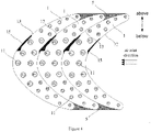
- a heat exchanger fin, a heat exchanger, an indoor unit, and an air conditioner are described below according to some embodiments of the present disclosure with reference to Figure 1 to Figure 7 .
- the heat exchanger fin includes an integrally-formed fin body 1.
- the fin body 1 includes an air outlet contour line 13 arranged at one side and an air inlet contour line 12 arranged at the other side; and the fin body 1 is provided with a plurality of refrigerant pipe mounting holes 11 for allowing refrigerant pipes to be mounted.
- the fin body 1 is concave in a direction from an air inlet side to an air outlet side, forming a curved shape.
- the maximum distance point 14 is within 1/5 to 4/5 of the air inlet contour line 12; and a straight line where the maximum distance point 14 is located extends along an air inlet direction for the heat exchanger fin.
- the maximum distance point 14 is located within a region where an air volume of an inlet air flow is maximum, thus allowing to increase a size of a region of the fin body 1 where the air volume is high and to reduce a size of a region of the fin body 1 where the air volume is low, thereby improving utilization of the fin body 1, so that heat transfer efficiency is improved when the fin body 1 is provided with the refrigerant pipes.
- the air inlet contour line 12 and the air outlet contour line 13 of the fin body 1 each are provided with a process notch 15, to facilitate tailoring of the fin body 1 during processing.
- the heat exchanger fin includes an integrally-formed fin body 1.
- the fin body 1 includes an air outlet contour line 13 arranged at one side and an air inlet contour line 12 arranged at the other side; and the fin body 1 is provided with a plurality of refrigerant pipe mounting holes 11 for allowing refrigerant pipes to be mounted.
- the fin body 1 is concave in a direction from an air inlet side to an air outlet side, forming a curved shape.
- the air inlet contour line 12 and the air outlet contour line 13 are connected by arcs at the flanks of the heat exchanger fin. There is a unique maximum value H3 for the distance between the air inlet contour line 12 and the air outlet contour line 13 of the fin body 1. Along a direction from a first end to a second end of the air inlet contour line 12, the maximum distance point 14 is within 1/5 to 4/5 of the air inlet contour line 12; and a straight line where the maximum distance point 14 is located extends along an air inlet direction for the heat exchanger fin.
- the maximum distance point 14 is located within a region where an air volume of an inlet air flow is maximum, thus allowing to increase a size of a region of the fin body 1 where the air volume is high and to reduce a size of a region of the fin body 1 where the air volume is low, thereby improving utilization of the fin body 1, so that heat transfer efficiency is improved when the fin body 1 is provided with the refrigerant pipe.
- the distance between the air inlet contour line 12 and the air outlet contour line 13 of the fin body 1 is H3, corresponding to which the internal diameter of the refrigerant pipe mounting hole 11 is P1; while at a first position point 17, on the straight line of the curvature radius of the air outlet contour line 13 of the fin body 1 or on the straight line of the curvature radius of the air inlet contour line 12 of the fin body 1, the distance between the air inlet contour line 12 and the air outlet contour line 13 of the fin body 1 is H4, corresponding to which the internal diameter of the refrigerant pipe mounting hole 11 is P2, where H3>H4 and P1>P2.
- the heat exchanger fin includes an integrally-formed fin body 1.
- the fin body 1 includes an air outlet contour line 13 arranged at one side and an air inlet contour line 12 arranged at the other side; and the fin body 1 is provided with a plurality of refrigerant pipe mounting holes 11 for allowing refrigerant pipes to be mounted.
- the fin body 1 is concave in a direction from an air inlet side to an air outlet side, forming a curved shape.
- the air inlet contour line 12 and the air outlet contour line 13 are connected by arcs at the flanks of the heat exchanger fin. There is a unique maximum value H3 for the distance between the air inlet contour line 12 and the air outlet contour line 13 of the fin body 1. Along a direction from a first end to a second end of the air inlet contour line 12, the maximum distance point 14 is within 1/5 to 4/5 of the air inlet contour line 12; and a straight line where the maximum distance point 14 is located extends along an air inlet direction for the heat exchanger fin.
- the maximum distance point 14 is located within a region where an air volume of an inlet air flow is maximum, thus allowing to increase a size of a region of the fin body 1 where the air volume is high and to reduce a size of a region of the fin body 1 where the air volume is low, thereby improving utilization of the fin body 1, so that heat transfer efficiency is improved when the fin body 1 is provided with the refrigerant pipe.
- the distance between the air inlet contour line 12 and the air outlet contour line 13 of the fin body 1 is H3; the distance of circle centers between two adjacent refrigerant pipe mounting holes 11 is Q1, corresponding to which the internal diameter of the refrigerant pipe mounting hole is P1; while at a first position point 17, on the straight line of the curvature radius of the air outlet contour line 13 of the fin body 1 or on the straight line of the curvature radius of the air inlet contour line 12 of the fin body 1, the distance between the air inlet contour line 12 and the air outlet contour line 13 of the fin body 1 is H4; the distance of circle centers between two adjacent refrigerant pipe mounting holes 11 is Q2, corresponding to which the internal diameter of the refrigerant pipe mounting hole is P2, where H3>H4, Q1>Q2 and P1>P2.
- the air inlet contour line 12 and the air outlet contour line 13 of the fin body 1 each are provided with a process notch 15, to facilitate tailoring of the fin body 1 during processing.
- the heat exchanger fin includes an integrally-formed fin body 1.
- the fin body 1 includes an air outlet contour line 13 arranged at one side and an air inlet contour line 12 arranged at the other side; and the fin body 1 is provided with a plurality of refrigerant pipe mounting holes 11 for allowing refrigerant pipes to be mounted.
- the fin body 1 is concave in a direction from an air inlet side to an air outlet side, forming a curved shape.
- the maximum distance point 14 is within 1/5 to 4/5 of the air inlet contour line 12; and a straight line where the maximum distance point 14 is located extends along an air inlet direction for the heat exchanger fin.
- the maximum distance point 14 is located within a region where an air volume of an inlet air flow is maximum, thus allowing to increase a size of a region of the fin body 1 where the air volume is high and to reduce a size of a region of the fin body 1 where the air volume is low, thereby improving utilization of the fin body 1, so that heat transfer efficiency is improved when the fin body 1 is provided with the refrigerant pipe.
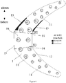
- the air inlet contour line 12 of the fin body 1 overlaps with part of the air outlet contour line 13 after translation, thereby minimizing an area of a waste region between two adjacent fin bodies 1 in an entire piece of raw material when processing the fin body 1, with the waste region 5 only existing between the flanks of adjacent fin bodies 1, thus facilitating to improve material utilization and reducing manufacture cost.
- the air inlet contour line 12 and the air outlet contour line 13 of the fin body 1 each are provided with a process notch 15, to facilitate tailoring of the fin body 1 during processing.
- the process notch 15 at the air inlet contour line 12 of each fin body 1 corresponds to the process notch 15 at the air outlet contour line 13 of the adjacent fin body 1, for easy tailoring during processing.
- a waste rate can be controlled below 6%, which is even lower than that of traditional non-standard shaped tailoring from a rectangle slice.
- the heat exchanger fin includes an integrally-formed fin body 1.
- the fin body 1 includes an air outlet contour line 13 arranged at one side and an air inlet contour line 12 arranged at the other side; and the fin body 1 is provided with a plurality of refrigerant pipe mounting holes 11 for allowing refrigerant pipes to be mounted.
- the fin body 1 is concave in a direction from an air inlet side to an air outlet side, forming a curved shape.
- the maximum distance point 14 is within 1/5 to 4/5 of the air inlet contour line 12; and a straight line where the maximum distance point 14 is located extends along an air inlet direction for the heat exchanger fin.
- the maximum distance point 14 is located within a region where an air volume of an inlet air flow is maximum, thus allowing to increase a size of a region of the fin body 1 where the air volume is high and to reduce a size of a region of the fin body 1 where the air volume is low, thereby improving utilization of the fin body 1, so that heat transfer efficiency is improved when the fin body 1 is provided with the refrigerant pipe.
- the air inlet contour line 12 and the air outlet contour line 13 of the fin body 1 each are provided with a process notch 15, to facilitate tailoring of the fin body 1 during processing.
- the air inlet contour line 12 of the fin body 1 exactly overlaps with part of the air outlet contour line 13 after translation, thereby minimizing an area of a waste region between two adjacent fin bodies 1 in an entire piece of raw material when processing the fin body 1, with the waste region 5 only existing between the flanks of adjacent fin bodies 1.
- the entire length of the air inlet contour line 12 of the fin body 1 is divided unequally by the straight line corresponding to the maximum distance, where one part length of the air inlet contour line 12 that is above the straight line corresponding to the maximum distance is longer than the other part length of the air inlet contour line 12 that is below the straight line corresponding to the maximum distance. Accordingly, one part length of the air outlet contour line 13 of the fin body 1 that is above the straight line corresponding to the maximum distance is longer than the other part length of the air outlet contour line 13 that is below the straight line corresponding to the maximum distance.
- the air inlet contour line 12 of the fin body 1 includes five arc segments connected in sequence, and the adjacent arc segments are of gradually decreasing curvatures from the center to the flanks of the heat exchanger fin; accordingly, the air outlet contour line 13 also includes five arc segments connected in sequence, and each arc segment of the air outlet contour line 13 is of a curvature identical to that of the corresponding arc segment of the air inlet contour line 12, such that the fin body 1 is divided into five regions with different curvatures from above to below.
- H1, H2, H3, H4 and H5 are respective distances between the air inlet contour line 12 and the air outlet contour line 13 within the five regions, H1 ⁇ H2 ⁇ H3, and H5 ⁇ H4 ⁇ H3.
- a plane where the air inlet direction for the fin body 1 is located is referred to as a first plane 61, i.e., the horizontal plane as shown in Figure 1 is the first plane 61; a plane which is perpendicular to the first plane 61 is a second plane 62, i.e., the vertical plane as shown in Figure 1 is the second plane 62.
- the fin body 1 is of a projection size L1 on the second plane 62; the part of the fin body 1 above the straight line corresponding to the maximum distance is of a projection size L2 on the first plane 61 and a projection size L5 on the second plane 62; and the part of the fin body 1 below the straight line corresponding to the maximum distance is of a projection size L3 on the first plane 61 and a projection size L4 on the second plane 62, where L3 ⁇ L2 ⁇ L1 and L4 ⁇ L5.
- the related projection size may also comply with L2 ⁇ L3 and/or L5 ⁇ L4.
- the fin body 1 may also be symmetrical relative to the straight line corresponding to the maximum distance.
- the straight line where the maximum distance is located is the straight line corresponding to the maximum distance.
- the heat exchanger fin includes an integrally-formed fin body 1.
- the fin body 1 includes an air outlet contour line 13 arranged at one side and an air inlet contour line 12 arranged at the other side; and the fin body 1 is provided with a plurality of refrigerant pipe mounting holes 11 for allowing refrigerant pipes to be mounted.
- the fin body 1 is concave in a direction from an air inlet side to an air outlet side, forming a curved shape.
- the heat exchanger fin is formed as an equidistant region 16 at the center.
- the distance between the air inlet contour line 12 and the air outlet contour line 13 is equal on the straight line of the curvature radius of the air outlet contour line 13 of the fin body 1.
- the air inlet contour line 12 and the air outlet contour line 13 within the equidistant region 16 are arcs, which are concave in the direction from the air inlet side to the air outlet side.
- the equidistant region 16 is located at the center where an air volume of an inlet air flow is maximum, thus allowing to increase a size of a region of the fin body 1 where the air volume is high and to reduce a size of a region of the fin body 1 where the air volume is low, thereby improving utilization of the fin body 1, so that heat transfer efficiency is improved when the fin body 1 is provided with the refrigerant pipe.
- the air inlet contour line 12 and the air outlet contour line 13 of the fin body 1 each are provided with a process notch 15, to facilitate tailoring of the fin body 1 during processing.
- the heat exchanger fin includes an integrally-formed fin body 1.
- the fin body 1 includes an air outlet contour line 13 arranged at one side and an air inlet contour line 12 arranged at the other side; and the fin body 1 is provided with a plurality of refrigerant pipe mounting holes 11 for allowing refrigerant pipes to be mounted.
- the fin body 1 is concave in a direction from an air inlet side to an air outlet side, forming a curved shape.
- the heat exchanger fin is formed as an equidistant region 16 at the center.
- the distance between the air inlet contour line 12 and the air outlet contour line 13 is equal on the straight line of the curvature radius of the air outlet contour line 13 of the fin body 1.
- the air inlet contour line 12 and the air outlet contour line 13 within the equidistant region 16 are straight lines, which are perpendicular to an air inlet direction.
- the equidistant region 16 is located at the center where an air volume of an inlet air flow is maximum, thus allowing to increase a size of a region of the fin body 1 where the air volume is high and to reduce a size of a region of the fin body 1 where the air volume is low, thereby improving utilization of the fin body 1, so that heat transfer efficiency is improved when the fin body 1 is provided with the refrigerant pipe.
- the air inlet contour line 12 and the air outlet contour line 13 of the fin body 1 each are provided with a process notch 15, to facilitate tailoring of the fin body 1 during processing.
- the heat exchanger fin includes an integrally-formed fin body 1.
- the fin body 1 includes an air outlet contour line 13 arranged at one side and an air inlet contour line 12 arranged at the other side; and the fin body 1 is provided with a plurality of refrigerant pipe mounting holes 11 for allowing refrigerant pipes to be mounted.
- the fin body 1 is concave in a direction from an air inlet side to an air outlet side, forming a curved shape.
- the maximum distance point 14 is within 1/5 to 4/5 of the air inlet contour line 12; and a straight line where the maximum distance point 14 is located extends along an air inlet direction for the heat exchanger fin.
- the maximum distance point 14 is located within a region where an air volume of an inlet air flow is maximum, thus allowing to increase a size of a region of the fin body 1 where the air volume is high and to reduce a size of a region of the fin body 1 where the air volume is low, thereby improving utilization of the fin body 1, so that heat transfer efficiency is improved when the fin body 1 is provided with the refrigerant pipe.
- a distance between adjacent refrigerant pipe mounting holes 11 is positively correlated with a diameter of the refrigerant pipe mounting hole 11, i.e., the larger the diameter of the refrigerant pipe mounting hole 11, the longer the distance between adjacent refrigerant pipe mounting holes 11.
- the air inlet contour line 12 of the fin body 1 exactly overlaps with part of the air outlet contour line 13 after translation, thereby minimizing an area of a waste region between two adjacent fin bodies 1 in an entire piece of raw material when processing the fin body 1, with the waste region 5 only existing between the flanks of adjacent fin bodies 1.
- the air inlet contour line 12 and the air outlet contour line 13 of the fin body 1 each are provided with a process notch 15.
- the process notch 15 at the air inlet contour line 12 of each fin body 1 corresponds to the process notch 15 at the air outlet contour line 13 of the adjacent fin body 1, for easy tailoring during processing.
- the entire length of the air inlet contour line 12 of the fin body 1 is divided unequally by the straight line corresponding to the maximum distance, where one part length of the air inlet contour line 12 that is above the straight line corresponding to the maximum distance is longer than the other part length of the air inlet contour line 12 that is below the straight line corresponding to the maximum distance. Accordingly, one part length of the air outlet contour line 13 of the fin body 1 that is above the straight line corresponding to the maximum distance is longer than the other part length of the air outlet contour line 13 that is below the straight line corresponding to the maximum distance.
- the air inlet contour line 12 of the fin body 1 includes five arc segments connected in sequence, and the adjacent arc segments are of gradually decreasing curvatures from the center to the flanks of the heat exchanger fin; accordingly, the air outlet contour line 13 of the fin body 1 also includes five arc segments connected in sequence, and each arc segment of the air outlet contour line 13 is of a curvature identical to that of the corresponding arc segment of the air inlet contour line 12, such that the fin body 1 is divided into five regions with different curvatures from above to below.
- H1, H2, H3, H4 and H5 are respective distances between the air inlet contour line 12 and the air outlet contour line 13 within the five regions, where H3 is the maximum distance, H1 ⁇ H2 ⁇ H3, and H5 ⁇ H4 ⁇ H3.
- a plane where the air inlet direction for the fin body 1 is located is referred to as a first plane 61, i.e., the horizontal plane as shown in Figure 1 is the first plane 61, a plane perpendicular to the first plane 61 is a second plane 62, i.e., the vertical plane as shown in Figure 1 is the second plane 62.
- the fin body 1 is of a projection size L1 on the second plane 62; the part of the fin body 1 above the straight line corresponding to the maximum distance is of a projection size L2 on the first plane 61 and a projection size L5 on the second plane 62; and the part of the fin body 1 below the straight line corresponding to the maximum distance is of a projection size L3 on the first plane 61 and a projection size L4 on the second plane 62, where L3 ⁇ L2 ⁇ L1 and L4 ⁇ L5.
- the related projection size may also comply with L2 ⁇ L3 and/or L5 ⁇ L4.
- the fin body 1 may also be symmetrical relative to the straight line corresponding to the maximum distance.
- the straight line where the maximum distance is located is the straight line corresponding to the maximum distance.
- the heat exchanger fin includes an integrally-formed fin body 1.
- the fin body 1 includes an air outlet contour line 13 arranged at one side and an air inlet contour line 12 arranged at the other side; and the fin body 1 is provided with a plurality of refrigerant pipe mounting holes 11 for allowing refrigerant pipes to be mounted.
- the fin body 1 is concave in a direction from an air inlet side to an air outlet side, forming a curved shape.
- an internal diameter of the refrigerant pipe mounting hole 11 also gradually decreases from the center to the flanks of the heat exchanger fin; the distance between the air inlet contour line 12 and the air outlet contour line 13 of the fin body 1 corresponding to the refrigerant pipe mounting hole 11 is positively correlated with the internal diameter of the refrigerant pipe mounting hole 11; and the internal diameter of each refrigerant pipe mounting hole 11 is linear-positively correlated with a distance of circle centers between any two adjacent refrigerant pipe mounting holes 11.
- the air inlet contour line 12 and the air outlet contour line 13 are connected by arcs at the flanks of the heat exchanger fin. There is a unique maximum value H3 for the distance between the air inlet contour line 12 and the air outlet contour line 13 of the fin body 1.
- the maximum distance point 14 is within 1/5 to 4/5 of the air inlet contour line 12; and a straight line where the maximum distance point 14 is located extends along an air inlet direction for the heat exchanger fin.
- the maximum distance point 14 is located within a region where an air volume of an inlet air flow is maximum, thus allowing to increase a size of a region of the fin body 1 where the air volume is high and to reduce a size of a region of the fin body 1 where the air volume is low, thereby improving utilization of the fin body 1, so that heat transfer efficiency is improved when the fin body 1 is provided with the refrigerant pipe.
- the distance between the air inlet contour line 12 and the air outlet contour line 13 of the fin body 1 is H3, corresponding to which the internal diameter of the refrigerant pipe mounting hole 11 is P1, and the distance of circle centers between two adjacent refrigerant pipe mounting holes 11 is Q1; while at a first position point 17, on the straight line of the curvature radius of the air outlet contour line 13 of the fin body 1 or on the straight line of the curvature radius of the air inlet contour line 12 of the fin body 1, the distance between the air inlet contour line 12 and the air outlet contour line 13 of the fin body 1 is H4, corresponding to which the internal diameter of the refrigerant pipe mounting hole 11 is P2, and the distance of circle centers between two adjacent refrigerant pipe mounting holes 11 is Q2, where H3>H4, P1>P2 and Q1>
- the air inlet contour line 12 of the fin body 1 exactly overlaps with part of the air outlet contour line 13 after translation, thereby minimizing an area of a waste region between two adjacent fin bodies 1 in an entire piece of raw material when processing the fin body 1, with the waste region 5 only existing between the flanks of adjacent fin bodies 1.
- the air inlet contour line 12 and the air outlet contour line 13 of the fin body 1 each are provided with a process notch 15.
- the process notch 15 at the air inlet contour line 12 of each fin body 1 corresponds to the process notch 15 at the air outlet contour line 13 of the adjacent fin body 1, for easy tailoring during processing.
- the entire length of the air inlet contour line 12 of the fin body 1 is divided unequally by the straight line corresponding to the maximum distance, where one part length of the air inlet contour line 12 that is above the straight line corresponding to the maximum distance is longer than the other part length of the air inlet contour line 12 that is below the straight line corresponding to the maximum distance. Accordingly, one part length of the air outlet contour line 13 of the fin body 1 that is above the straight line corresponding to the maximum distance is longer than the other part length of the air outlet contour line 13 that is below the straight line corresponding to the maximum distance.
- the air inlet contour line 12 of the fin body 1 includes five arc segments connected in sequence, and the adjacent arc segments are of gradually decreasing curvatures from the center to the flanks of the heat exchanger fin; accordingly, the air outlet contour line 13 also includes five arc segments connected in sequence, and each arc segment is of a curvature identical to that of the corresponding arc segment at the air inlet contour line 12, such that the fin body 1 is divided into five regions with different curvatures from above to below.
- H1, H2, H3, H4 and H5 are respective distances between the air inlet contour line 12 and the air outlet contour line 13 within the five regions, where H3 is the maximum distance, H1 ⁇ H2 ⁇ H3, and H5 ⁇ H4 ⁇ H3.
- a plane where the air inlet direction for the fin body 1 is located is referred to as a first plane 61, i.e., the horizontal plane as shown in Figure 1 is the first plane 61, a plane which is perpendicular to the first plane 61 is a second plane 62, i.e., the vertical plane as shown in Figure 1 is the second plane 62.
- the fin body 1 is of a projection size L1 on the second plane 62; the part of the fin body 1 above the straight line corresponding to the maximum distance is of a projection size L2 on the first plane 61 and a projection size L5 on the second plane 62; and the part of the fin body 1 below the straight line corresponding to the maximum distance is of a projection size L3 on the first plane 61 and a projection size L4 on the second plane 62, where L3 ⁇ L2 ⁇ L1 and L4 ⁇ L5.
- the related projection size may also comply with L2 ⁇ L3 and/or L5 ⁇ L4.
- the fin body 1 may also be symmetrical relative to the straight line corresponding to the maximum distance.
- a heat exchanger including a plurality of the heat exchanger fins as defined in any one of embodiments 1 to 9 and a refrigerant pipe.
- the plurality of the heat exchanger fins is arranged side by side, and a distance between any two adjacent heat exchanger fins is not less than a preset interval, so as to guarantee normal circulation of the inlet air flow.
- the pipe diameter of the refrigerant pipe fits with a diameter of a refrigerant pipe mounting hole 11 of the heat exchanger fin.
- the refrigerant pipe is arranged passing through the refrigerant pipe mounting hole 11, thus allowing heat exchange of air when the inlet air flow becomes in contact with the heat exchanger, achieving heat exchange by the heat exchanger.
- the heat exchanger in this embodiment has all beneficial advantages as described for the heat exchanger fin as described in any one of the above embodiments 1 to 9, which is not elaborated in detail here.
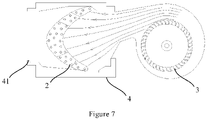
- the indoor unit includes a shell 4, a fan 3 and the heat exchanger 2 as described in the above embodiment 10.
- the shell 4 is provided with an air inlet (not shown in Figure 7 ) and an air outlet 41; the fan 3 and the heat exchanger 2 are arranged within the shell 4, where the fan 3 drives air to flow from the air inlet to the air outlet 41.
- the heat exchanger 2 is arranged between the fan 3 and the air outlet 41 of the shell 4, and the heat exchanger 2 is arranged correspondingly to the fan 3, allowing heat exchange for the air flow send by the fan 3 before discharge from the air outlet 41 of the shell 4, thus achieving adjustment of air temperature.
- the indoor unit in this embodiment has all beneficial advantages as described for the heat exchanger 2 as described in the above embodiment 10, which is not elaborated in detail here.
- an air conditioner including an outdoor unit and the indoor unit as described in the above embodiment 11 which is connected to the outdoor unit, thus allowing heat exchange for air by the indoor unit through refrigerant interaction between the outdoor unit and the indoor unit, achieving adjustment of air temperature.
- the air conditioner in this embodiment has all beneficial advantages as described for the indoor unit as described in the above embodiment 11, which is not elaborated in detail here.
- terms such as “first”, “second” and “third” are used herein for purposes of description and are not intended to indicate or imply relative importance; term “a plurality of” means two or more than two this features, unless specified otherwise; terms “mounted”, “connected”, “coupled”, “fixed” and the like are used broadly, and may be, for example, fixed connections, detachable connections, or integrated connections; may also be direct connections or indirect connections via intervening structures, which can be understood by those ordinary skilled in the art according to specific situations.
- orientation or position relationship such as “above”, “below”, “left”, “right”, “front”, “rear” and the like should be construed to refer to the orientation or position relationship as described or as shown in the drawings. These terms are merely for convenience and concision of description and do not alone indicate or imply that the device or unit referred to must have a particular orientation or must be configured or operated in a particular orientation. Thus, it cannot be understood to limit the present disclosure.
Landscapes
- Engineering & Computer Science (AREA)
- Physics & Mathematics (AREA)
- Thermal Sciences (AREA)
- Mechanical Engineering (AREA)
- General Engineering & Computer Science (AREA)
- Geometry (AREA)
- Chemical & Material Sciences (AREA)
- Combustion & Propulsion (AREA)
- Heat-Exchange Devices With Radiators And Conduit Assemblies (AREA)
Abstract
Description
- This application claims priority to and the benefit of the
Chinese Patent Application No. 201911014034.5 filed on October 23, 2019 Chinese Patent Application No. 201911194822.7 filed on November 28, 2019 - The present disclosure relates to the field of air conditioning technology, in particular to a heat exchanger fin, a heat exchanger, an indoor unit, and an air conditioner.
- At present, a heat exchanger fin commonly used in a heat exchanger of an indoor unit is mostly in a rectangular shape with equal widths or having a partially non-standard shaped structure at both ends of the rectangle, and the pipeline flow paths at the heat exchanger fin are also arranged uniformly according to a certain rule. However, air flow out of a fan of an indoor unit is generally non-uniform, which easily leads to excess air volume for some regions of the heat exchanger and also results in material waste for some regions, causing low utilization of the heat exchanger and affecting heat exchange efficiency of the air conditioner.
- The present disclosure aims to solve at least one technical problem existing in the prior art or the related art.
- For this, one objective of the present disclosure is to provide a heat exchanger fin.
- Another objective of the present disclosure is to provide a heat exchanger.
- A further objective of the present disclosure is to provide an indoor unit.
- A further objective of the present disclosure is to provide an air conditioner.
- In order to achieve the above objectives, in a first aspect, the present disclosure provides in embodiments a heat exchanger fin, including: a fin body, including an air outlet contour line arranged at one side and an air inlet contour line arranged at the other side, and provided with a plurality of refrigerant pipe mounting holes, wherein a distance between the air inlet contour line and the air outlet contour line of the fin body, on a straight line of a curvature radius of the air outlet contour line of the fin body or on a straight line of a curvature radius of the air inlet contour line of the fin body, gradually decreases from a center to flanks of the heat exchanger fin.
- According to embodiments in the first aspect of the present disclosure, the heat exchanger fin includes a fin body; the fin body is provided with a plurality of refrigerant pipe mounting holes for allowing refrigerant pipes to be mounted; the distance between the air inlet contour line and the air outlet contour line of the fin body, on the straight line of the curvature radius of the air outlet contour line of the fin body or on the straight line of the curvature radius of the air inlet contour line of the fin body, is arranged to gradually decrease from a center to flanks of the heat exchanger fin, such that the fin body is of a larger area of the central region than that of the flank region, thus allowing to increase the area of the central region of the fin body where the air volume is high and to reduce the area of the flank region of the fin body where the air volume is low, thereby improving utilization of the fin body, enhancing heat exchange performance, and reducing energy consumption; at the same time, the material waste for the region where the air volume is low is reduced, thus facilitating reduced manufacture cost.
- It should be noted that an air flow out of a fan of a commonly-used air conditioner (particularly an indoor unit) is non-uniform, where the air volume of the central air flow is generally greater than that of the periphery air flow.
- In addition, the heat exchanger fin in the above embodiment of the present disclosure may further have the following additional technical features.
- In the above embodiment, the fin body is a one-piece structure. It should be noted that the one-piece structure of the fin body specifically refers to a structure that is integrally formed during processing or manufacturing process. In some examples, forming integrally is achieved by cutting or tailoring a raw material.
- In the above embodiment, the fin body is concave in a direction from an air inlet side to an air outlet side, and at least part of the air outlet contour line overlaps with the air inlet contour line after translation.
- In this embodiment, the fin body is arranged to be concave in the direction from the air inlet side to the air outlet side, such that the fin body is in a curved shape, thus allowing to enlarge a distance between the central region of the fin body and an outlet where the air flow comes from, thereby reducing air pressure on the heat exchanger fin; and at least part of the air outlet contour line of the fin body is arranged to overlap with the air inlet contour line after translation, so as to facilitate to tailoring of the fin body during processing, reduce waste material during processing and accordingly reduce manufacture cost. It would be understood that the fin body is shaped and tailored from an entire piece of raw material during manufacture and processing, therefore reducing the distance between two fins across the entire piece of raw material increases material utilization.
- In the above embodiment, a first end and a second end of the air inlet contour line are connected to the air outlet contour line respectively; a maximum distance between the air inlet contour line and the air outlet contour line is within 1/5 to 4/5 of the air inlet contour line along a direction from the first end to the second end.
- In this embodiment, the first end and the second end of the air inlet contour line are arranged to connect to the air outlet contour line respectively, forming a complete outer contour of the fin body; the maximum distance between the air inlet contour line and the air outlet contour line is within 1/5 to 4/5 of the air inlet contour line along a direction from the first end to the second end, so that the maximum distance is away from the first end and the second end (i.e., the maximum distance is located within the central region of the fin body, thus allowing a region with the largest area of the fin body to correspond to air flow in higher air volume, thereby improving utilization of the heat exchanger fin.
- In the above embodiment, a straight line corresponding to the maximum distance extends along an air inlet direction for the heat exchanger fin.
- In this embodiment, the straight line corresponding to the maximum distance is arranged to extend along the air inlet direction for the heat exchanger fin, so that the extending direction of the fin body is consistent with the air inlet direction, so as to increase a contact area for the fin body and the inlet air flow, thus facilitating to improving heat exchange efficiency. It should be noted that the air inlet direction is an overall direction of a movement trend of the inlet air flow. There is a maximum distance between the air inlet contour line and the air outlet contour line of the fin body on the straight line of the curvature radius of the air outlet contour line of the fin body or on the straight line of the curvature radius of the air inlet contour line of the fin body, where the straight line where the maximum distance is located is the straight line corresponding to the maximum distance.
- In the above embodiment, the fin body is symmetrical relative to the straight line corresponding to the maximum distance.
- In this embodiment, the fin body is arranged to be symmetrical relative to the straight line corresponding to the maximum distance, so that two parts of the fin body which are divided by the straight line corresponding to the maximum distance are in similar shapes, thus providing the heat exchanger including the heat exchanger fin with uniform heat exchange performance, and facilitating to tailoring the heat exchanger fin during processing.
- In the above embodiment, a length of the air inlet contour line at one side of the straight line corresponding to the maximum distance is greater than a length of the air inlet contour line at the other side of the straight line corresponding to the maximum distance.
- In this embodiment, the length of the air inlet contour line at one side of the straight line corresponding to the maximum distance is arranged to be greater than the length of the air inlet contour line at the other side of the straight line corresponding to the maximum distance, so that the fin body is in an essential asymmetric shape, thus allowing to increase an area of a region of the fin body where the air volume is high and to reduce an area of a region of the fin body where the air volume is low, which are arranged in accordance with different air volumes of the inlet air flow, thereby further improving utilization of the heat exchanger fin. It would be understood that the inlet air flow is non-uniform, where the air volume within the air flow is not necessarily exactly symmetric.
- In the above embodiment, the air outlet contour line includes five arc segments connected in sequence, and the adjacent arc segments are of gradually decreasing curvatures from the center to the flanks of the heat exchanger fin.
- In this embodiment, the air outlet contour line is arranged to include five arc segments connected in sequence, and the adjacent arc segments are arranged to be of gradually decreasing curvatures from the center to the flanks of the heat exchanger fin, so that different parts of the fin body are provided in different shapes by varying curvatures of different arc segments, thus facilitating to shaping and tailoring of the fin body during processing in accordance with the air volume of the inlet air flow.
- In the above embodiment, a plane where the air inlet direction for the fin body is located is a first plane, and a plane which is perpendicular to the first plane is a second plane; and the fin body is of a larger projection size on the second plane than that on the first plane.
- In this embodiment, a plane where the air inlet direction for the fin body is located is arranged to be a first plane, and a plane which is perpendicular to the first plane is arranged to be a second plane; and the fin body is arranged to be of a larger projection size on the second plane than that on the first plane, so that the fin body can be provided with an increased angle between the air inlet contour line and the air outlet contour line, thus facilitating to increasing an contact area between the refrigerant pipe arranged at the heat exchanger fin and the inlet air flow, thereby improving heat exchange efficiency.
- In the above embodiment, the fin body is of a larger projection size on the second plane at one side of the straight line corresponding to the maximum distance than that on the second plane at the other side of the straight line corresponding to the maximum distance.
- In this embodiment, the fin body is arranged to be of a larger projection size on the second plane at one side of the straight line corresponding to the maximum distance than that on the second plane at the other side of the straight line corresponding to the maximum distance, so that the fin body is provided in an asymmetric shape, and two parts of the fin body are provided with different projection sizes on the second plane (i.e., two parts of the fin body, which are divided by the straight line corresponding to the maximum distance, are of different sizes on a plane perpendicular to the air inlet direction), thus allowing a region with a larger size of the fin body to correspond to air flow in higher air volume and allowing a region with a smaller size of the fin body to correspond to the air flow in lower air volume, which are arranged in accordance with different air volumes of the inlet air flow, thereby improving utilization of the fin body and increasing heat exchange efficiency.
- In the above embodiment, the fin body is of a larger projection size on the first plane at one side of the straight line corresponding to the maximum distance than that on the first plane at the other side of the straight line corresponding to the maximum distance.
- In this embodiment, the fin body is arranged to be of a larger projection size on the first plane at one side of the straight line corresponding to the maximum distance than that on the first plane at the other side of the straight line corresponding to the maximum distance, so that the fin body is provided in an asymmetric shape, and two parts of the fin body are provided with different projection sizes on the first plane where the air inlet direction is located, thus allowing a region with a larger size of the fin body to correspond to air flow in higher air volume and allowing a region with a smaller size of the fin body to correspond to the air flow in lower air volume, which are arranged in accordance with different air volumes of the inlet air flow, thereby improving utilization of the fin body and increasing heat exchange efficiency.
- In the above embodiment, the heat exchanger fin is formed as an equidistant region at the center, and the distance between the air inlet contour line and the air outlet contour line is equal within the equidistant region.
- In this embodiment, the heat exchanger fin is arranged to be formed as an equidistant region at the center, and the distance between the air inlet contour line and the air outlet contour line is arranged to be equal within the equidistant region, so as to increase the area of the region of the fin body corresponding to the inlet air flow in higher air volume, thus improving utilization of the fin body and increasing heat exchange efficiency. It would be understood that the air volume of the central air flow is same or almost same with extremely low variation.
- In the above embodiment, the air inlet contour line and the air outlet contour line within the equidistant region are any one or any combination of an arc and a straight line.
- In this embodiment, the air inlet contour line and the air outlet contour line within the equidistant region may be in various shapes, including any one or any combination of an arc and a straight line, where the straight line is convenient for tailing of the fin body during processing, while the arc allows the air inlet contour line and the air outlet contour line streamlined, which is beneficial to reduce the wind resistance and make the air flow more smoothly.
- In the above embodiment, the number of the refrigerant pipe mounting holes is gradually decreased from the center to the flanks of the heat exchanger fin.
- In this embodiment, the number of the refrigerant pipe mounting holes is arranged to gradually decrease from the center to the flanks of the heat exchanger fin, so that the region of the fin body corresponding to the inlet air flow in higher air volume is provided with more refrigerant pipes, and the region of the fin body corresponding to the inlet air flow in low air volume is provided with fewer refrigerant pipes, fully utilizing the inlet air flow and improving heat exchange efficiency, and facilitating to reducing the area of the region of the fin body corresponding to the inlet air flow in low air volume to save material.
- In the above embodiment, a distance between adjacent refrigerant pipe mounting holes is positively correlated with a diameter of the refrigerant pipe mounting hole.
- In this embodiment, in order to reduce mutual influence between the refrigerant pipes, adjacent refrigerant pipes are maintained at a certain distance. As the total area of the fin body is limited, the distance between adjacent refrigerant pipe mounting holes is arranged to be positively correlated with the diameter of the refrigerant pipe mounting hole, so as to arrange the refrigerant pipes in a reasonable way within the limited space. In other words, the greater a pipe diameter of the refrigerant pipe is, the farther the distance between adjacent refrigerant pipes is; and the smaller the pipe diameter of the refrigerant pipe is, the nearer between adjacent refrigerant pipes, thereby improving utilization of the heat exchanger fin.
- In the above embodiment, an inner diameter of the refrigerant pipe mounting hole is gradually decreased from the center to the flanks of the heat exchanger fin.
- In this embodiment, the inner diameter of the refrigerant pipe mounting hole is arranged to gradually decrease from the center to the flanks of the heat exchanger fin, so that the refrigerant pipes are of different pipe diameters depending on different positions where the refrigerant pipe is located at the fin body, thus allowing a refrigerant pipe with a larger pipe diameter to be arranged at the region of the fin body where the area is larger, and allowing a refrigerant pipe with a smaller pipe diameter to be arranged at the region of the fin body where the area is lower, thereby facilitating to improving utilization of the heat exchange fin, enhancing heat exchange performance, and reducing energy consumption; at the same time, as the material waste for the region where the air volume is low is reduced, thus facilitating to reduction of manufacture cost.
- The fin body may be a one-piece structure, or may also be a split combined structure. It should be note that the one-piece structure of the fin body specifically refers to a structure that is integrally formed during processing or manufacturing process. In some examples, forming integrally is achieved by cutting or tailoring a raw material.
- In the above embodiment, the distance between the air inlet contour line and the air outlet contour line of the fin body corresponding to the refrigerant pipe mounting hole is positively correlated with an internal diameter of each refrigerant pipe mounting hole, on a straight line of a curvature radius of the air outlet contour line of the fin body or on a straight line of a curvature radius of the air inlet contour line of the fin body.
- In this embodiment, the distance between the air inlet contour line and the air outlet contour line of the fin body corresponding to the refrigerant pipe mounting hole is arranged to be positively correlated with an internal diameter of each refrigerant pipe mounting hole on the straight line of the curvature radius of the air outlet contour line of the fin body or on the straight line of the curvature radius of the air inlet contour line of the fin body. In other words, the greater the distance between the air inlet contour line and the air outlet contour line of the fin body is, the larger the internal diameter of the corresponding refrigerant pipe mounting hole is, so that the pipe diameter of the refrigerant pipe to be mounted in the refrigerant pipe mount hole is accordingly larger; vice versa, the smaller the distance between the air inlet contour line and the air outlet contour line of the fin body is, the smaller the internal diameter of the corresponding refrigerant pipe mounting hole is, so that the pipe diameter of the refrigerant pipe to be mounted in the refrigerant pipe mount hole is accordingly smaller, thus fully utilizing the fin body depending on the areas of different regions, arranging matching refrigerant pipe mounting holes for the corresponding part, thereby improving utilization of the heat exchanger fin, enhancing heat exchange performance and reducing energy consumption when the heat exchanger fin is mounted with the refrigerant pipes matching with the refrigerant pipe mounting holes.
- In the above embodiment, an internal diameter of each refrigerant pipe mounting hole is linear-positively correlated with a distance of circle centers between any two adjacent refrigerant pipe mounting holes, on a straight line of a curvature radius of the air outlet contour line of the fin body or on a straight line of a curvature radius of the air inlet contour line of the fin body.
- In this embodiment, the internal diameter of each refrigerant pipe mounting hole is arranged to be linear-positively correlated with a distance of circle centers between any two adjacent refrigerant pipe mounting holes, on the straight line of the curvature radius of the air outlet contour line of the fin body or on the straight line of the curvature radius of the air inlet contour line of the fin body, so that the internal diameter of the refrigerant pipe mounting hole is arranged depending on the distance of circle centers between any two adjacent refrigerant pipe mounting holes. In other words, the greater the distance of circle centers between two adjacent refrigerant pipe mounting holes is, the larger the internal diameter of the refrigerant pipe mounting hole is; vice versa, the smaller the distance of circle centers between two adjacent refrigerant pipe mounting holes is, the smaller the internal diameter of the refrigerant pipe mounting hole is, so that adjacent refrigerant pipe mounting holes are maintained at a proper distance of circle centers, thereby improving utilization of the heat exchanger fin, enhancing heat exchange performance and reducing energy consumption when the heat exchanger fin is mounted with the refrigerant pipes matching with the refrigerant pipe mounting holes. It would be understood that an over large distance of circle centers between adjacent refrigerant pipe mounting holes will easily lead to insufficient heat exchange for the refrigerant pipe that influences the heat exchange efficiency; an over close distance of circle centers between adjacent refrigerant pipe mounting holes will easily lead to material waste for the refrigerant pipe and also lead to an over small area of a region of the fin body between two adjacent refrigerant pipe mounting holes, resulting in easy break and thus adversely affecting reliability of the heat exchanger fin.
- In a second aspect, the present disclosure provides in embodiments a heat exchanger, including: a plurality of the heat exchanger fins as described in any one of embodiments in the first aspect, which are arranged side by side, wherein a distance between any two adjacent heat exchanger fins is not less than a preset interval; and a refrigerant pipe, wherein a pipe diameter of the refrigerant pipe fits with a size of a refrigerant pipe mounting hole of the heat exchanger fin, and the refrigerant pipe passes through the refrigerant pipe mounting hole.
- According to embodiments in the second aspect, the heat exchanger includes a plurality of the heat exchanger fins as described in any one of embodiments in the first aspect and a refrigerant pipe, where the plurality of the heat exchanger fins is arranged side by side, forming an array of the heat exchanger fins; and the pipe diameter of the refrigerant pipe fits with the size of the refrigerant pipe mounting hole. The refrigerant pipe mounting holes arranged at the array of the heat exchanger fins are provided with the refrigerant pipes, thus allowing heat exchange between the refrigerant pipes and the inlet air flow, thereby achieving adjustment of air temperature. The heat exchanger in this embodiment has all beneficial advantages as described for the heat exchanger fin as described in any one of embodiments in the first aspect of the present disclosure, which is not elaborated in detail here.
- In a third aspect, the present disclosure provides in embodiments an indoor unit, including: a shell, provided with an air inlet and an air outlet; a fan, arranged inside the shell; and the heat exchanger as described in embodiments in the second aspect, which is arranged inside the shell and arranged corresponding to the fan.
- According to embodiments in the third aspect, the indoor unit includes a shell, a fan and the heat exchanger as described in embodiments in the second aspect, where the shell is provided with an air inlet and an air outlet, thus forming an air flow channel inside the shell; the fan is arranged inside the shell, so as to drive air to flow from the air inlet to the air outlet by means of rotation of the fan; and the heat exchanger is arranged correspondingly to the fan inside the shell, where specifically, the heat exchanger is arranged between the fan and the air outlet of the shell, such that the fan drives air to flow to the heat exchanger for heat exchange before discharge from the air outlet of the shell, thus achieving adjustment of air temperature. The indoor unit in this embodiment has all beneficial advantages as described for the heat exchanger as described in embodiments in the second aspect of the present disclosure, which is not elaborated in detail here.
- In a fourth aspect, the present disclosure provides in embodiments an air conditioner, including an outdoor unit; and the indoor unit as described in embodiments in the third aspect, which is connected to the outdoor unit.
- According to embodiments in the fourth aspect, the air conditioner includes an outdoor unit and the indoor unit as described in embodiments in the third aspect, which is connected to the outdoor unit, so that various air conditioning modes can be realized through refrigerant interaction between the outdoor unit and the indoor unit. The air conditioner in this embodiment has all beneficial advantages as described for the indoor unit as described in embodiments in the third aspect of the present disclosure, which is not elaborated in detail here.
- Additional aspects and advantages of the present disclosure will become apparent in the description below, or learned by practice of the present disclosure.
- The above and/or additional aspects and advantages of the present disclosure will become obvious and understandable with the following description for embodiments by combining the accompanying drawings.
-
Figure 1 shows a schematic structural view of a heat exchanger fin according to an embodiment of the present disclosure; -
Figure 2 shows a schematic structural view of a heat exchanger fin according to an embodiment of the present disclosure; -
Figure 3 shows a schematic structural view of a heat exchanger fin according to an embodiment of the present disclosure; -
Figure 4 shows a schematic structural view of a processing layout of heat exchanger fins according to an embodiment of the present disclosure; -
Figure 5 shows a schematic structural view of a heat exchanger fin according to an embodiment of the present disclosure; -
Figure 6 shows a schematic structural view of a heat exchanger fin according to an embodiment of the present disclosure; -
Figure 7 shows a schematic diagram of an internal structure of an indoor unit according to an embodiment of the present disclosure. - The correspondence between reference signs and components in
Figure 1 to Figure 7 is as follows.
1 fin body; 11 refrigerant pipe mounting hole; 12 air inlet contour line; 13 air outlet contour line; 14 distance maximum point; 15 process notch; 16 equidistant region; 17 first position point; 2 heat exchanger; 3 fan; 4 shell; 41 air outlet; 5 waste region; 61 first plane; 62 second plane. - In order to understand the above objectives, features and advantages of the present disclosure more clearly, the present disclosure will be further described in detail below in conjunction with the accompanying drawings and specific embodiments. It should be noted that embodiments and features in embodiments of the present disclosure can be combined with each other without conflict.
- In the following description, many specific details are set forth in order to fully understand the present disclosure. However, the present disclosure can also be implemented in other ways different from those described herein. Therefore, the protection scope of the present disclosure is not limited by the specific embodiments disclosed below.
- A heat exchanger fin, a heat exchanger, an indoor unit, and an air conditioner are described below according to some embodiments of the present disclosure with reference to
Figure 1 to Figure 7 . - In this embodiment, there is provided a heat exchanger fin. As shown in
Figure 1 , the heat exchanger fin includes an integrally-formedfin body 1. Thefin body 1 includes an airoutlet contour line 13 arranged at one side and an airinlet contour line 12 arranged at the other side; and thefin body 1 is provided with a plurality of refrigerantpipe mounting holes 11 for allowing refrigerant pipes to be mounted. Thefin body 1 is concave in a direction from an air inlet side to an air outlet side, forming a curved shape. The distance between the airinlet contour line 12 and the airoutlet contour line 13 of thefin body 1, on a straight line of a curvature radius of the airoutlet contour line 13 of thefin body 1 or on a straight line of a curvature radius of the airinlet contour line 12 of thefin body 1, gradually decreases from a center to flanks of the heat exchanger fin. Accordingly, an internal diameter of the refrigerantpipe mounting hole 11 also gradually decreases from the center to the flanks of the heat exchanger fin; and the airinlet contour line 12 and the airoutlet contour line 13 are connected by arcs at the flanks of the heat exchanger fin. There is a unique maximum value H3 for the distance between the airinlet contour line 12 and the airoutlet contour line 13 of thefin body 1. Along a direction from a first end to a second end of the airinlet contour line 12, themaximum distance point 14 is within 1/5 to 4/5 of the airinlet contour line 12; and a straight line where themaximum distance point 14 is located extends along an air inlet direction for the heat exchanger fin. Specifically, themaximum distance point 14 is located within a region where an air volume of an inlet air flow is maximum, thus allowing to increase a size of a region of thefin body 1 where the air volume is high and to reduce a size of a region of thefin body 1 where the air volume is low, thereby improving utilization of thefin body 1, so that heat transfer efficiency is improved when thefin body 1 is provided with the refrigerant pipes. It should be noted that, as shown inFigure 1 , the airinlet contour line 12 and the airoutlet contour line 13 of thefin body 1 each are provided with aprocess notch 15, to facilitate tailoring of thefin body 1 during processing. - In this embodiment, there is provided a heat exchanger fin. As shown in
Figure 2 , the heat exchanger fin includes an integrally-formedfin body 1. Thefin body 1 includes an airoutlet contour line 13 arranged at one side and an airinlet contour line 12 arranged at the other side; and thefin body 1 is provided with a plurality of refrigerantpipe mounting holes 11 for allowing refrigerant pipes to be mounted. Thefin body 1 is concave in a direction from an air inlet side to an air outlet side, forming a curved shape. The distance between the airinlet contour line 12 and the airoutlet contour line 13 of thefin body 1, on a straight line of a curvature radius of the airoutlet contour line 13 of thefin body 1 or on a straight line of a curvature radius of the airinlet contour line 12 of thefin body 1, gradually decreases from a center to flanks of the heat exchanger fin. Accordingly, an internal diameter of the refrigerantpipe mounting hole 11 also gradually decreases from the center to the flanks of the heat exchanger fin; and the distance between the airinlet contour line 12 and the airoutlet contour line 13 of thefin body 1 corresponding to the refrigerantpipe mounting hole 11 is positively correlated with the internal diameter of the refrigerantpipe mounting hole 11. The airinlet contour line 12 and the airoutlet contour line 13 are connected by arcs at the flanks of the heat exchanger fin. There is a unique maximum value H3 for the distance between the airinlet contour line 12 and the airoutlet contour line 13 of thefin body 1. Along a direction from a first end to a second end of the airinlet contour line 12, themaximum distance point 14 is within 1/5 to 4/5 of the airinlet contour line 12; and a straight line where themaximum distance point 14 is located extends along an air inlet direction for the heat exchanger fin. Specifically, themaximum distance point 14 is located within a region where an air volume of an inlet air flow is maximum, thus allowing to increase a size of a region of thefin body 1 where the air volume is high and to reduce a size of a region of thefin body 1 where the air volume is low, thereby improving utilization of thefin body 1, so that heat transfer efficiency is improved when thefin body 1 is provided with the refrigerant pipe. In addition, at themaximum distance point 14, on the straight line of the curvature radius of the airoutlet contour line 13 of thefin body 1 or on the straight line of the curvature radius of the airinlet contour line 12 of thefin body 1, the distance between the airinlet contour line 12 and the airoutlet contour line 13 of thefin body 1 is H3, corresponding to which the internal diameter of the refrigerantpipe mounting hole 11 is P1; while at afirst position point 17, on the straight line of the curvature radius of the airoutlet contour line 13 of thefin body 1 or on the straight line of the curvature radius of the airinlet contour line 12 of thefin body 1, the distance between the airinlet contour line 12 and the airoutlet contour line 13 of thefin body 1 is H4, corresponding to which the internal diameter of the refrigerantpipe mounting hole 11 is P2, where H3>H4 and P1>P2. In other words, the longer the distance between the airinlet contour line 12 and the airoutlet contour line 13 of thefin body 1, the larger the internal diameter of the corresponding refrigerantpipe mounting hole 11. It should be noted that, as shown inFigure 2 , the airinlet contour line 12 and the airoutlet contour line 13 of thefin body 1 each are provided with aprocess notch 15, to facilitate tailoring of thefin body 1 during processing. - In this embodiment, there is provided a heat exchanger fin. As shown in
Figure 3 , the heat exchanger fin includes an integrally-formedfin body 1. Thefin body 1 includes an airoutlet contour line 13 arranged at one side and an airinlet contour line 12 arranged at the other side; and thefin body 1 is provided with a plurality of refrigerantpipe mounting holes 11 for allowing refrigerant pipes to be mounted. Thefin body 1 is concave in a direction from an air inlet side to an air outlet side, forming a curved shape. The distance between the airinlet contour line 12 and the airoutlet contour line 13 of thefin body 1 on a straight line of a curvature radius of the airoutlet contour line 13 of thefin body 1 or on a straight line of a curvature radius of the airinlet contour line 12 of thefin body 1, gradually decreases from a center to flanks of the heat exchanger fin. Accordingly, an internal diameter of the refrigerantpipe mounting hole 11 also gradually decreases from the center to the flanks of the heat exchanger fin; and the internal diameter of each refrigerantpipe mounting hole 11 is linear-positively correlated with a distance of circle centers between any two adjacent refrigerant pipe mounting holes 11. The airinlet contour line 12 and the airoutlet contour line 13 are connected by arcs at the flanks of the heat exchanger fin. There is a unique maximum value H3 for the distance between the airinlet contour line 12 and the airoutlet contour line 13 of thefin body 1. Along a direction from a first end to a second end of the airinlet contour line 12, themaximum distance point 14 is within 1/5 to 4/5 of the airinlet contour line 12; and a straight line where themaximum distance point 14 is located extends along an air inlet direction for the heat exchanger fin. Specifically, themaximum distance point 14 is located within a region where an air volume of an inlet air flow is maximum, thus allowing to increase a size of a region of thefin body 1 where the air volume is high and to reduce a size of a region of thefin body 1 where the air volume is low, thereby improving utilization of thefin body 1, so that heat transfer efficiency is improved when thefin body 1 is provided with the refrigerant pipe. In addition, at themaximum distance point 14, on the straight line of the curvature radius of the airoutlet contour line 13 of thefin body 1 or on the straight line of the curvature radius of the airinlet contour line 12 of thefin body 1, the distance between the airinlet contour line 12 and the airoutlet contour line 13 of thefin body 1 is H3; the distance of circle centers between two adjacent refrigerantpipe mounting holes 11 is Q1, corresponding to which the internal diameter of the refrigerant pipe mounting hole is P1; while at afirst position point 17, on the straight line of the curvature radius of the airoutlet contour line 13 of thefin body 1 or on the straight line of the curvature radius of the airinlet contour line 12 of thefin body 1, the distance between the airinlet contour line 12 and the airoutlet contour line 13 of thefin body 1 is H4; the distance of circle centers between two adjacent refrigerantpipe mounting holes 11 is Q2, corresponding to which the internal diameter of the refrigerant pipe mounting hole is P2, where H3>H4, Q1>Q2 and P1>P2. In other words, the longer the distance between the airinlet contour line 12 and the airoutlet contour line 13 of thefin body 1, the greater the distance of circle centers between adjacent refrigerantpipe mounting holes 11, and the larger the internal diameter of the corresponding refrigerantpipe mounting hole 11. It should be noted that, as shown inFigure 3 , the airinlet contour line 12 and the airoutlet contour line 13 of thefin body 1 each are provided with aprocess notch 15, to facilitate tailoring of thefin body 1 during processing. - In this embodiment, there is provided a heat exchanger fin. As shown in
Figure 1 , the heat exchanger fin includes an integrally-formedfin body 1. Thefin body 1 includes an airoutlet contour line 13 arranged at one side and an airinlet contour line 12 arranged at the other side; and thefin body 1 is provided with a plurality of refrigerantpipe mounting holes 11 for allowing refrigerant pipes to be mounted. Thefin body 1 is concave in a direction from an air inlet side to an air outlet side, forming a curved shape. The distance between the airinlet contour line 12 and the airoutlet contour line 13 of thefin body 1, on a straight line of a curvature radius of the airoutlet contour line 13 of thefin body 1 or on a straight line of a curvature radius of the airinlet contour line 12 of thefin body 1, gradually decreases from a center to flanks of the heat exchanger fin. Accordingly, an internal diameter of the refrigerantpipe mounting hole 11 also gradually decreases from the center to the flanks of the heat exchanger fin; and the airinlet contour line 12 and the airoutlet contour line 13 are connected by arcs at the flanks of the heat exchanger fin. There is a unique maximum value H3 for the distance between the airinlet contour line 12 and the airoutlet contour line 13 of thefin body 1. Along a direction from a first end to a second end of the airinlet contour line 12, themaximum distance point 14 is within 1/5 to 4/5 of the airinlet contour line 12; and a straight line where themaximum distance point 14 is located extends along an air inlet direction for the heat exchanger fin. Specifically, themaximum distance point 14 is located within a region where an air volume of an inlet air flow is maximum, thus allowing to increase a size of a region of thefin body 1 where the air volume is high and to reduce a size of a region of thefin body 1 where the air volume is low, thereby improving utilization of thefin body 1, so that heat transfer efficiency is improved when thefin body 1 is provided with the refrigerant pipe. - As shown in
Figure 4 , the airinlet contour line 12 of thefin body 1 overlaps with part of the airoutlet contour line 13 after translation, thereby minimizing an area of a waste region between twoadjacent fin bodies 1 in an entire piece of raw material when processing thefin body 1, with thewaste region 5 only existing between the flanks ofadjacent fin bodies 1, thus facilitating to improve material utilization and reducing manufacture cost. The airinlet contour line 12 and the airoutlet contour line 13 of thefin body 1 each are provided with aprocess notch 15, to facilitate tailoring of thefin body 1 during processing. Theprocess notch 15 at the airinlet contour line 12 of eachfin body 1 corresponds to theprocess notch 15 at the airoutlet contour line 13 of theadjacent fin body 1, for easy tailoring during processing. - In the present embodiment, during manufacture of the heat exchanger fin, a waste rate can be controlled below 6%, which is even lower than that of traditional non-standard shaped tailoring from a rectangle slice.
- In this embodiment, there is provided a heat exchanger fin. As shown in
Figure 1 , the heat exchanger fin includes an integrally-formedfin body 1. Thefin body 1 includes an airoutlet contour line 13 arranged at one side and an airinlet contour line 12 arranged at the other side; and thefin body 1 is provided with a plurality of refrigerantpipe mounting holes 11 for allowing refrigerant pipes to be mounted. Thefin body 1 is concave in a direction from an air inlet side to an air outlet side, forming a curved shape. The distance between the airinlet contour line 12 and the airoutlet contour line 13 of thefin body 1, on a straight line of a curvature radius of the airoutlet contour line 13 of thefin body 1 or on a straight line of a curvature radius of the airinlet contour line 12 of thefin body 1, gradually decreases from a center to flanks of the heat exchanger fin. Accordingly, an internal diameter of the refrigerantpipe mounting hole 11 also gradually decreases from the center to the flanks of the heat exchanger fin; and the airinlet contour line 12 and the airoutlet contour line 13 are connected by arcs at the flanks of the heat exchanger fin. There is a unique maximum value H3 for the distance between the airinlet contour line 12 and the airoutlet contour line 13 of thefin body 1. Along a direction from a first end to a second end of the airinlet contour line 12, themaximum distance point 14 is within 1/5 to 4/5 of the airinlet contour line 12; and a straight line where themaximum distance point 14 is located extends along an air inlet direction for the heat exchanger fin. Specifically, themaximum distance point 14 is located within a region where an air volume of an inlet air flow is maximum, thus allowing to increase a size of a region of thefin body 1 where the air volume is high and to reduce a size of a region of thefin body 1 where the air volume is low, thereby improving utilization of thefin body 1, so that heat transfer efficiency is improved when thefin body 1 is provided with the refrigerant pipe. - As shown in
Figure 4 , the airinlet contour line 12 and the airoutlet contour line 13 of thefin body 1 each are provided with aprocess notch 15, to facilitate tailoring of thefin body 1 during processing. The airinlet contour line 12 of thefin body 1 exactly overlaps with part of the airoutlet contour line 13 after translation, thereby minimizing an area of a waste region between twoadjacent fin bodies 1 in an entire piece of raw material when processing thefin body 1, with thewaste region 5 only existing between the flanks ofadjacent fin bodies 1. - As shown in
Figure 1 , the entire length of the airinlet contour line 12 of thefin body 1 is divided unequally by the straight line corresponding to the maximum distance, where one part length of the airinlet contour line 12 that is above the straight line corresponding to the maximum distance is longer than the other part length of the airinlet contour line 12 that is below the straight line corresponding to the maximum distance. Accordingly, one part length of the airoutlet contour line 13 of thefin body 1 that is above the straight line corresponding to the maximum distance is longer than the other part length of the airoutlet contour line 13 that is below the straight line corresponding to the maximum distance. In some examples, the airinlet contour line 12 of thefin body 1 includes five arc segments connected in sequence, and the adjacent arc segments are of gradually decreasing curvatures from the center to the flanks of the heat exchanger fin; accordingly, the airoutlet contour line 13 also includes five arc segments connected in sequence, and each arc segment of the airoutlet contour line 13 is of a curvature identical to that of the corresponding arc segment of the airinlet contour line 12, such that thefin body 1 is divided into five regions with different curvatures from above to below. On the straight line of the curvature radius of the airoutlet contour line 13 of thefin body 1, H1, H2, H3, H4 and H5 are respective distances between the airinlet contour line 12 and the airoutlet contour line 13 within the five regions, H1<H2<H3, and H5<H4<H3. - In some examples, a plane where the air inlet direction for the
fin body 1 is located is referred to as afirst plane 61, i.e., the horizontal plane as shown inFigure 1 is thefirst plane 61; a plane which is perpendicular to thefirst plane 61 is asecond plane 62, i.e., the vertical plane as shown inFigure 1 is thesecond plane 62. Thefin body 1 is of a projection size L1 on thesecond plane 62; the part of thefin body 1 above the straight line corresponding to the maximum distance is of a projection size L2 on thefirst plane 61 and a projection size L5 on thesecond plane 62; and the part of thefin body 1 below the straight line corresponding to the maximum distance is of a projection size L3 on thefirst plane 61 and a projection size L4 on thesecond plane 62, where L3<L2<L1 and L4<L5. - It should be noted that, for the heat exchanger fin in this embodiment, the related projection size may also comply with L2≤L3 and/or L5≤L4. In some examples, the
fin body 1 may also be symmetrical relative to the straight line corresponding to the maximum distance. - On the straight line of the curvature radius of the air
outlet contour line 12 of thefin body 1 or on the straight line of the curvature radius of the airinlet contour line 11 of thefin body 1, there is the maximum distance between the airinlet contour line 11 and the airoutlet contour line 12 of thefin body 1. The straight line where the maximum distance is located is the straight line corresponding to the maximum distance. - In this embodiment, there is provided a heat exchanger fin. As shown in
Figure 5 , the heat exchanger fin includes an integrally-formedfin body 1. Thefin body 1 includes an airoutlet contour line 13 arranged at one side and an airinlet contour line 12 arranged at the other side; and thefin body 1 is provided with a plurality of refrigerantpipe mounting holes 11 for allowing refrigerant pipes to be mounted. Thefin body 1 is concave in a direction from an air inlet side to an air outlet side, forming a curved shape. The distance between the airinlet contour line 12 and the airoutlet contour line 13 of thefin body 1, on a straight line of a curvature radius of the airoutlet contour line 13 of thefin body 1 or on a straight line of a curvature radius of the airinlet contour line 12 of thefin body 1, gradually decreases from a center to flanks of the heat exchanger fin. Accordingly, an internal diameter of the refrigerantpipe mounting hole 11 also gradually decreases from the center to the flanks of the heat exchanger fin; and the airinlet contour line 12 and the airoutlet contour line 13 are connected by arcs at the flanks of the heat exchanger fin. The heat exchanger fin is formed as anequidistant region 16 at the center. Within theequidistant region 16, the distance between the airinlet contour line 12 and the airoutlet contour line 13 is equal on the straight line of the curvature radius of the airoutlet contour line 13 of thefin body 1. In other words, there are more than one maximum distance H3 between the airinlet contour line 12 and the airoutlet contour line 13; and all maximum distance points 14 are within 1/5 to 4/5 of the airinlet contour line 12 along a first end to a second end of the airinlet contour line 12. Specifically, the airinlet contour line 12 and the airoutlet contour line 13 within theequidistant region 16 are arcs, which are concave in the direction from the air inlet side to the air outlet side. Theequidistant region 16 is located at the center where an air volume of an inlet air flow is maximum, thus allowing to increase a size of a region of thefin body 1 where the air volume is high and to reduce a size of a region of thefin body 1 where the air volume is low, thereby improving utilization of thefin body 1, so that heat transfer efficiency is improved when thefin body 1 is provided with the refrigerant pipe. It should be noted that, as shown inFigure 5 , the airinlet contour line 12 and the airoutlet contour line 13 of thefin body 1 each are provided with aprocess notch 15, to facilitate tailoring of thefin body 1 during processing. - In this embodiment, there is provided a heat exchanger fin. As shown in
Figure 6 , the heat exchanger fin includes an integrally-formedfin body 1. Thefin body 1 includes an airoutlet contour line 13 arranged at one side and an airinlet contour line 12 arranged at the other side; and thefin body 1 is provided with a plurality of refrigerantpipe mounting holes 11 for allowing refrigerant pipes to be mounted. Thefin body 1 is concave in a direction from an air inlet side to an air outlet side, forming a curved shape. The distance between the airinlet contour line 12 and the airoutlet contour line 13 of thefin body 1, on a straight line of a curvature radius of the airoutlet contour line 13 of thefin body 1 or on a straight line of a curvature radius of the airinlet contour line 12 of thefin body 1, gradually decreases from a center to flanks of the heat exchanger fin. Accordingly, an internal diameter of the refrigerantpipe mounting hole 11 also gradually decreases from the center to the flanks of the heat exchanger fin; and the airinlet contour line 12 and the airoutlet contour line 13 are connected by arcs at the flanks of the heat exchanger fin. The heat exchanger fin is formed as anequidistant region 16 at the center. Within theequidistant region 16, the distance between the airinlet contour line 12 and the airoutlet contour line 13 is equal on the straight line of the curvature radius of the airoutlet contour line 13 of thefin body 1. In other words, there are more than one maximum distance H3 between the airinlet contour line 12 and the airoutlet contour line 13; and all maximum distance points 14 are within 1/5 to 4/5 of the airinlet contour line 12 along a first end to a second end of the airinlet contour line 12. Specifically, the airinlet contour line 12 and the airoutlet contour line 13 within theequidistant region 16 are straight lines, which are perpendicular to an air inlet direction. Theequidistant region 16 is located at the center where an air volume of an inlet air flow is maximum, thus allowing to increase a size of a region of thefin body 1 where the air volume is high and to reduce a size of a region of thefin body 1 where the air volume is low, thereby improving utilization of thefin body 1, so that heat transfer efficiency is improved when thefin body 1 is provided with the refrigerant pipe. It should be noted that, as shown inFigure 6 , the airinlet contour line 12 and the airoutlet contour line 13 of thefin body 1 each are provided with aprocess notch 15, to facilitate tailoring of thefin body 1 during processing. - In this embodiment, there is provided a heat exchanger fin. As shown in
Figure 1 , the heat exchanger fin includes an integrally-formedfin body 1. Thefin body 1 includes an airoutlet contour line 13 arranged at one side and an airinlet contour line 12 arranged at the other side; and thefin body 1 is provided with a plurality of refrigerantpipe mounting holes 11 for allowing refrigerant pipes to be mounted. Thefin body 1 is concave in a direction from an air inlet side to an air outlet side, forming a curved shape. The distance between the airinlet contour line 12 and the airoutlet contour line 13 of thefin body 1, on a straight line of a curvature radius of the airoutlet contour line 13 of thefin body 1 or on a straight line of a curvature radius of the airinlet contour line 12 of thefin body 1, gradually decreases from a center to flanks of the heat exchanger fin. Accordingly, an internal diameter of the refrigerantpipe mounting hole 11 also gradually decreases from the center to the flanks of the heat exchanger fin; and the airinlet contour line 12 and the airoutlet contour line 13 are connected by arcs at the flanks of the heat exchanger fin. There is a unique maximum value H3 for the distance between the airinlet contour line 12 and the airoutlet contour line 13 of thefin body 1. Along a direction from a first end to a second end of the airinlet contour line 12, themaximum distance point 14 is within 1/5 to 4/5 of the airinlet contour line 12; and a straight line where themaximum distance point 14 is located extends along an air inlet direction for the heat exchanger fin. Specifically, themaximum distance point 14 is located within a region where an air volume of an inlet air flow is maximum, thus allowing to increase a size of a region of thefin body 1 where the air volume is high and to reduce a size of a region of thefin body 1 where the air volume is low, thereby improving utilization of thefin body 1, so that heat transfer efficiency is improved when thefin body 1 is provided with the refrigerant pipe. A distance between adjacent refrigerantpipe mounting holes 11 is positively correlated with a diameter of the refrigerantpipe mounting hole 11, i.e., the larger the diameter of the refrigerantpipe mounting hole 11, the longer the distance between adjacent refrigerant pipe mounting holes 11. - As shown in
Figure 4 , the airinlet contour line 12 of thefin body 1 exactly overlaps with part of the airoutlet contour line 13 after translation, thereby minimizing an area of a waste region between twoadjacent fin bodies 1 in an entire piece of raw material when processing thefin body 1, with thewaste region 5 only existing between the flanks ofadjacent fin bodies 1. The airinlet contour line 12 and the airoutlet contour line 13 of thefin body 1 each are provided with aprocess notch 15. Theprocess notch 15 at the airinlet contour line 12 of eachfin body 1 corresponds to theprocess notch 15 at the airoutlet contour line 13 of theadjacent fin body 1, for easy tailoring during processing. - As shown in
Figure 1 , the entire length of the airinlet contour line 12 of thefin body 1 is divided unequally by the straight line corresponding to the maximum distance, where one part length of the airinlet contour line 12 that is above the straight line corresponding to the maximum distance is longer than the other part length of the airinlet contour line 12 that is below the straight line corresponding to the maximum distance. Accordingly, one part length of the airoutlet contour line 13 of thefin body 1 that is above the straight line corresponding to the maximum distance is longer than the other part length of the airoutlet contour line 13 that is below the straight line corresponding to the maximum distance. Specifically, the airinlet contour line 12 of thefin body 1 includes five arc segments connected in sequence, and the adjacent arc segments are of gradually decreasing curvatures from the center to the flanks of the heat exchanger fin; accordingly, the airoutlet contour line 13 of thefin body 1 also includes five arc segments connected in sequence, and each arc segment of the airoutlet contour line 13 is of a curvature identical to that of the corresponding arc segment of the airinlet contour line 12, such that thefin body 1 is divided into five regions with different curvatures from above to below. On the straight line of the curvature radius of the airoutlet contour line 13 of thefin body 1, H1, H2, H3, H4 and H5 are respective distances between the airinlet contour line 12 and the airoutlet contour line 13 within the five regions, where H3 is the maximum distance, H1<H2<H3, and H5<H4<H3. Further, a plane where the air inlet direction for thefin body 1 is located is referred to as afirst plane 61, i.e., the horizontal plane as shown inFigure 1 is thefirst plane 61, a plane perpendicular to thefirst plane 61 is asecond plane 62, i.e., the vertical plane as shown inFigure 1 is thesecond plane 62. Thefin body 1 is of a projection size L1 on thesecond plane 62; the part of thefin body 1 above the straight line corresponding to the maximum distance is of a projection size L2 on thefirst plane 61 and a projection size L5 on thesecond plane 62; and the part of thefin body 1 below the straight line corresponding to the maximum distance is of a projection size L3 on thefirst plane 61 and a projection size L4 on thesecond plane 62, where L3<L2<L1 and L4<L5. - It should be noted that, for the heat exchanger fin in this embodiment, the related projection size may also comply with L2≤L3 and/or L5≤L4. In some example, the
fin body 1 may also be symmetrical relative to the straight line corresponding to the maximum distance. - On the straight line of the curvature radius of the air
outlet contour line 12 of the fin body or on the straight line of the curvature radius of the air inlet contour line of the fin body, there is the maximum distance between the air inlet contour line and the air outlet contour line of the fin body. The straight line where the maximum distance is located is the straight line corresponding to the maximum distance. - In this embodiment, there is provided a heat exchanger fin. As shown in
Figure 1 , the heat exchanger fin includes an integrally-formedfin body 1. Thefin body 1 includes an airoutlet contour line 13 arranged at one side and an airinlet contour line 12 arranged at the other side; and thefin body 1 is provided with a plurality of refrigerantpipe mounting holes 11 for allowing refrigerant pipes to be mounted. Thefin body 1 is concave in a direction from an air inlet side to an air outlet side, forming a curved shape. The distance between the airinlet contour line 12 and the airoutlet contour line 13 of thefin body 1, on a straight line of a curvature radius of the airoutlet contour line 13 of thefin body 1 or on a straight line of a curvature radius of the airinlet contour line 12 of thefin body 1, gradually decreases from a center to flanks of the heat exchanger fin. Accordingly, an internal diameter of the refrigerantpipe mounting hole 11 also gradually decreases from the center to the flanks of the heat exchanger fin; the distance between the airinlet contour line 12 and the airoutlet contour line 13 of thefin body 1 corresponding to the refrigerantpipe mounting hole 11 is positively correlated with the internal diameter of the refrigerantpipe mounting hole 11; and the internal diameter of each refrigerantpipe mounting hole 11 is linear-positively correlated with a distance of circle centers between any two adjacent refrigerant pipe mounting holes 11. The airinlet contour line 12 and the airoutlet contour line 13 are connected by arcs at the flanks of the heat exchanger fin. There is a unique maximum value H3 for the distance between the airinlet contour line 12 and the airoutlet contour line 13 of thefin body 1. Along a direction from a first end to a second end of the airinlet contour line 12, themaximum distance point 14 is within 1/5 to 4/5 of the airinlet contour line 12; and a straight line where themaximum distance point 14 is located extends along an air inlet direction for the heat exchanger fin. - Specifically, as shown in
Figure 3 , themaximum distance point 14 is located within a region where an air volume of an inlet air flow is maximum, thus allowing to increase a size of a region of thefin body 1 where the air volume is high and to reduce a size of a region of thefin body 1 where the air volume is low, thereby improving utilization of thefin body 1, so that heat transfer efficiency is improved when thefin body 1 is provided with the refrigerant pipe. In addition, at themaximum distance point 14, on the straight line of the curvature radius of the airoutlet contour line 13 of thefin body 1 or on the straight line of the curvature radius of the airinlet contour line 12 of thefin body 1, the distance between the airinlet contour line 12 and the airoutlet contour line 13 of thefin body 1 is H3, corresponding to which the internal diameter of the refrigerantpipe mounting hole 11 is P1, and the distance of circle centers between two adjacent refrigerantpipe mounting holes 11 is Q1; while at afirst position point 17, on the straight line of the curvature radius of the airoutlet contour line 13 of thefin body 1 or on the straight line of the curvature radius of the airinlet contour line 12 of thefin body 1, the distance between the airinlet contour line 12 and the airoutlet contour line 13 of thefin body 1 is H4, corresponding to which the internal diameter of the refrigerantpipe mounting hole 11 is P2, and the distance of circle centers between two adjacent refrigerantpipe mounting holes 11 is Q2, where H3>H4, P1>P2 and Q1>Q2. In other words, the longer the distance between the airinlet contour line 12 and the airoutlet contour line 13 of thefin body 1, the greater the distance of circle centers between two adjacent refrigerantpipe mounting holes 11, and the larger the internal diameter of the corresponding refrigerantpipe mounting hole 11. - As shown in
Figure 4 , the airinlet contour line 12 of thefin body 1 exactly overlaps with part of the airoutlet contour line 13 after translation, thereby minimizing an area of a waste region between twoadjacent fin bodies 1 in an entire piece of raw material when processing thefin body 1, with thewaste region 5 only existing between the flanks ofadjacent fin bodies 1. The airinlet contour line 12 and the airoutlet contour line 13 of thefin body 1 each are provided with aprocess notch 15. Theprocess notch 15 at the airinlet contour line 12 of eachfin body 1 corresponds to theprocess notch 15 at the airoutlet contour line 13 of theadjacent fin body 1, for easy tailoring during processing. - As shown in
Figure 1 , the entire length of the airinlet contour line 12 of thefin body 1 is divided unequally by the straight line corresponding to the maximum distance, where one part length of the airinlet contour line 12 that is above the straight line corresponding to the maximum distance is longer than the other part length of the airinlet contour line 12 that is below the straight line corresponding to the maximum distance. Accordingly, one part length of the airoutlet contour line 13 of thefin body 1 that is above the straight line corresponding to the maximum distance is longer than the other part length of the airoutlet contour line 13 that is below the straight line corresponding to the maximum distance. Specifically, the airinlet contour line 12 of thefin body 1 includes five arc segments connected in sequence, and the adjacent arc segments are of gradually decreasing curvatures from the center to the flanks of the heat exchanger fin; accordingly, the airoutlet contour line 13 also includes five arc segments connected in sequence, and each arc segment is of a curvature identical to that of the corresponding arc segment at the airinlet contour line 12, such that thefin body 1 is divided into five regions with different curvatures from above to below. On the straight line of the curvature radius of the airoutlet contour line 13 of thefin body 1, H1, H2, H3, H4 and H5 are respective distances between the airinlet contour line 12 and the airoutlet contour line 13 within the five regions, where H3 is the maximum distance, H1<H2<H3, and H5<H4<H3. Further, a plane where the air inlet direction for thefin body 1 is located is referred to as afirst plane 61, i.e., the horizontal plane as shown inFigure 1 is thefirst plane 61, a plane which is perpendicular to thefirst plane 61 is asecond plane 62, i.e., the vertical plane as shown inFigure 1 is thesecond plane 62. Thefin body 1 is of a projection size L1 on thesecond plane 62; the part of thefin body 1 above the straight line corresponding to the maximum distance is of a projection size L2 on thefirst plane 61 and a projection size L5 on thesecond plane 62; and the part of thefin body 1 below the straight line corresponding to the maximum distance is of a projection size L3 on thefirst plane 61 and a projection size L4 on thesecond plane 62, where L3<L2<L1 and L4<L5. - It should be noted that, for the heat exchanger fin in this embodiment, the related projection size may also comply with L2≤L3 and/or L5≤L4. In some examples, the
fin body 1 may also be symmetrical relative to the straight line corresponding to the maximum distance. - On a straight line of the curvature radius of the air
outlet contour line 12 of thefin body 1 or on a straight line of the curvature radius of the airinlet contour line 11 of thefin body 1, there is the maximum distance between the airinlet contour line 11 and the airoutlet contour line 12 of thefin body 1. The straight line where the maximum distance is located is the straight line corresponding to the maximum distance. - In this embodiment, there is provided a heat exchanger, including a plurality of the heat exchanger fins as defined in any one of
embodiments 1 to 9 and a refrigerant pipe. The plurality of the heat exchanger fins is arranged side by side, and a distance between any two adjacent heat exchanger fins is not less than a preset interval, so as to guarantee normal circulation of the inlet air flow. The pipe diameter of the refrigerant pipe fits with a diameter of a refrigerantpipe mounting hole 11 of the heat exchanger fin. The refrigerant pipe is arranged passing through the refrigerantpipe mounting hole 11, thus allowing heat exchange of air when the inlet air flow becomes in contact with the heat exchanger, achieving heat exchange by the heat exchanger. The heat exchanger in this embodiment has all beneficial advantages as described for the heat exchanger fin as described in any one of theabove embodiments 1 to 9, which is not elaborated in detail here. - In this embodiment, there is provided an indoor unit. As shown in
Figure 7 , the indoor unit includes a shell 4, afan 3 and theheat exchanger 2 as described in the above embodiment 10. The shell 4 is provided with an air inlet (not shown inFigure 7 ) and anair outlet 41; thefan 3 and theheat exchanger 2 are arranged within the shell 4, where thefan 3 drives air to flow from the air inlet to theair outlet 41. Theheat exchanger 2 is arranged between thefan 3 and theair outlet 41 of the shell 4, and theheat exchanger 2 is arranged correspondingly to thefan 3, allowing heat exchange for the air flow send by thefan 3 before discharge from theair outlet 41 of the shell 4, thus achieving adjustment of air temperature. The indoor unit in this embodiment has all beneficial advantages as described for theheat exchanger 2 as described in the above embodiment 10, which is not elaborated in detail here. - In this embodiment, there is provided an air conditioner, including an outdoor unit and the indoor unit as described in the
above embodiment 11 which is connected to the outdoor unit, thus allowing heat exchange for air by the indoor unit through refrigerant interaction between the outdoor unit and the indoor unit, achieving adjustment of air temperature. The air conditioner in this embodiment has all beneficial advantages as described for the indoor unit as described in theabove embodiment 11, which is not elaborated in detail here. - The embodiments of the present disclosure are illustrated above with reference to drawings, which improve utilization of the heat exchanger fin; facilitate to improving heat exchange efficiency and reducing energy consumption; and reduce manufacture cost by decreasing the material waste.
- In present disclosure, terms such as "first", "second" and "third" are used herein for purposes of description and are not intended to indicate or imply relative importance; term " a plurality of" means two or more than two this features, unless specified otherwise; terms "mounted", "connected", "coupled", "fixed" and the like are used broadly, and may be, for example, fixed connections, detachable connections, or integrated connections; may also be direct connections or indirect connections via intervening structures, which can be understood by those ordinary skilled in the art according to specific situations.
- In the description of the present disclosure, it should be understood that, the terms indicating orientation or position relationship such as "above", "below", "left", "right", "front", "rear" and the like should be construed to refer to the orientation or position relationship as described or as shown in the drawings. These terms are merely for convenience and concision of description and do not alone indicate or imply that the device or unit referred to must have a particular orientation or must be configured or operated in a particular orientation. Thus, it cannot be understood to limit the present disclosure.
- Reference throughout this specification to "an embodiment", "some embodiments", "an example", "a specific example" or "some examples" means that a particular feature, structure, material, or characteristic described in connection with the embodiment or example is included in at least one embodiment or example of the present disclosure. Thus, the appearances of the phrases such as "in some embodiments", "in one embodiment", "in an embodiment", "in another example", "in an example", "in a specific example" or "in some examples", in various places throughout this specification are not necessarily referring to the same embodiment or example of the present disclosure. Furthermore, the particular features, structures, materials, or characteristics may be combined in any suitable manner in one or more embodiments or examples.
- The above are only preferred embodiments of the present disclosure, and are not intended to limit the present disclosure. For those skilled in the art, various modifications and changes can be made in the present disclosure. Any modification, equivalent replacement, improvement, etc. made within the spirit and principle of the present disclosure shall be included within the protection scope of the present disclosure.
Claims (21)
- A heat exchanger fin, comprising: a fin body, comprising an air outlet contour line arranged at one side and an air inlet contour line arranged at the other side, and provided with a plurality of refrigerant pipe mounting holes, wherein a distance between the air inlet contour line and the air outlet contour line of the fin body, on a straight line of a curvature radius of the air outlet contour line of the fin body or on a straight line of a curvature radius of the air inlet contour line of the fin body, gradually decreases from a center to flanks of the heat exchanger fin.
- The heat exchanger fin according to claim 1, wherein the fin body is a one-piece structure.
- The heat exchanger fin according to claim 1 or 2, wherein the fin body is concave in a direction from an air inlet side to an air outlet side of the fin body, and at least part of the air outlet contour line overlaps with the air inlet contour line after translation.
- The heat exchanger fin according to claim 3, wherein a first end and a second end of the air inlet contour line are connected to the air outlet contour line respectively; and a maximum distance between the air inlet contour line and the air outlet contour line is within 1/5 to 4/5 of the air inlet contour line along a direction from the first end to the second end.
- The heat exchanger fin according to claim 4, wherein a straight line corresponding to the maximum distance extends along an air inlet direction for the heat exchanger fin.
- The heat exchanger fin according to claim 5, wherein the fin body is symmetrical relative to the straight line corresponding to the maximum distance.
- The heat exchanger fin according to claim 5, wherein a length of the air inlet contour line at one side of the straight line corresponding to the maximum distance is greater than a length of the air inlet contour line at the other side of the straight line corresponding to the maximum distance.
- The heat exchanger fin according to claim 7, wherein the air outlet contour line comprises five arc segments connected in sequence, and the adjacent arc segments are of gradually decreasing curvatures from the center to the flanks of the heat exchanger fin.
- The heat exchanger fin according to claim 5, wherein a plane where the air inlet direction for the fin body is located is a first plane, and a plane which is perpendicular to the first plane is a second plane; and the fin body is of a larger projection size on the second plane than that on the first plane.
- The heat exchanger fin according to claim 9, wherein the fin body is of a larger projection size on the second plane at one side of the straight line corresponding to the maximum distance than that on the second plane at the other side of the straight line corresponding to the maximum distance.
- The heat exchanger fin according to claim 9, wherein the fin body is of a larger projection size on the first plane at one side of the straight line corresponding to the maximum distance than that on the first plane at the other side of the straight line corresponding to the maximum distance.
- The heat exchanger fin according to any one of claims 1 to 11, wherein the heat exchanger fin is formed as an equidistant region at the center, and the distance between the air inlet contour line and the air outlet contour line is equal within the equidistant region.
- The heat exchanger fin according to claim 12, wherein the air inlet contour line and the air outlet contour line within the equidistant region are any one or any combination of an arc and a straight line.
- The heat exchanger fin according to any one of claims 1 to 13, wherein the number of the refrigerant pipe mounting holes is gradually decreased from the center to the flanks of the heat exchanger fin.
- The heat exchanger fin according to claim 14, wherein a distance between adjacent refrigerant pipe mounting holes is positively correlated with a diameter of the refrigerant pipe mounting hole.
- The heat exchanger fin according to any one of claims 1 to 15, wherein an inner diameter of the refrigerant pipe mounting hole is gradually decreased from the center to the flanks of the heat exchanger fin.
- The heat exchanger fin according to any one of claims 1 to 16, wherein the distance between the air inlet contour line and the air outlet contour line of the fin body corresponding to the refrigerant pipe mounting hole is positively correlated with an internal diameter of each refrigerant pipe mounting hole, on a straight line of a curvature radius of the air outlet contour line of the fin body or on a straight line of a curvature radius of the air inlet contour line of the fin body.
- The heat exchanger fin according to any one of claims 1 to 17, wherein an internal diameter of each refrigerant pipe mounting hole is linear-positively correlated with a distance of circle centers between any two adjacent refrigerant pipe mounting holes, on a straight line of a curvature radius of the air outlet contour line of the fin body or on a straight line of a curvature radius of the air inlet contour line of the fin body.
- A heat exchanger, comprising: a plurality of the heat exchanger fins as defined in any one of claims 1 to 18, which are arranged side by side, wherein a distance between any two adjacent heat exchanger fins is not less than a preset interval; and a refrigerant pipe, wherein a pipe diameter of the refrigerant pipe fits with a size of a refrigerant pipe mounting hole of the heat exchanger fin, and the refrigerant pipe passes through the refrigerant pipe mounting hole.
- An indoor unit, comprising: a shell, provided with an air inlet and an air outlet; a fan, arranged inside the shell; and a heat exchanger as defined in claim 19, arranged inside the shell and arranged corresponding to the fan.
- An air conditioner, comprising: an outdoor unit; and an indoor unit as defined in claim 20, connected to the outdoor unit.
Applications Claiming Priority (3)
| Application Number | Priority Date | Filing Date | Title |
|---|---|---|---|
| CN201911014034.5A CN110701942B (en) | 2019-10-23 | 2019-10-23 | Heat Exchanger Fins, Heat Exchangers, Indoor Units and Air Conditioners |
| CN201911194822.7A CN110848814B (en) | 2019-11-28 | 2019-11-28 | Heat Exchanger Fins, Heat Exchangers, Indoor Units and Air Conditioners |
| PCT/CN2020/077477 WO2021077649A1 (en) | 2019-10-23 | 2020-03-02 | Heat exchanger fin, heat exchanger, indoor unit and air conditioner |
Publications (3)
| Publication Number | Publication Date |
|---|---|
| EP4030132A1 true EP4030132A1 (en) | 2022-07-20 |
| EP4030132A4 EP4030132A4 (en) | 2022-11-02 |
| EP4030132B1 EP4030132B1 (en) | 2026-03-25 |
Family
ID=75619605
Family Applications (1)
| Application Number | Title | Priority Date | Filing Date |
|---|---|---|---|
| EP20880266.0A Active EP4030132B1 (en) | 2019-10-23 | 2020-03-02 | Heat exchanger fin, heat exchanger, indoor unit and air conditioner |
Country Status (3)
| Country | Link |
|---|---|
| US (1) | US12215876B2 (en) |
| EP (1) | EP4030132B1 (en) |
| WO (1) | WO2021077649A1 (en) |
Family Cites Families (23)
| Publication number | Priority date | Publication date | Assignee | Title |
|---|---|---|---|---|
| US2055549A (en) * | 1934-05-18 | 1936-09-29 | Modine Mfg Co | Heat exchange device |
| US3763929A (en) * | 1972-01-03 | 1973-10-09 | N Wenig | Convection heat exchanger |
| US4771825A (en) * | 1987-01-08 | 1988-09-20 | Chen Hung Tai | Heat exchanger having replaceable extended heat exchange surfaces |
| US5157941A (en) * | 1991-03-14 | 1992-10-27 | Whirlpool Corporation | Evaporator for home refrigerator |
| JPH08338670A (en) * | 1995-06-12 | 1996-12-24 | Mitsubishi Heavy Ind Ltd | Heat transfer tube for heat exchanger |
| EP0816788A3 (en) * | 1996-06-24 | 1998-12-16 | Sanden Corporation | Multi-tube heat exchanger and air conditioner having the same |
| JPH1054685A (en) * | 1996-08-09 | 1998-02-24 | Daikin Ind Ltd | Heat exchanger and method of manufacturing the same |
| JP4511143B2 (en) | 2003-09-05 | 2010-07-28 | パナソニック株式会社 | Finned heat exchanger and manufacturing method thereof |
| WO2005088201A1 (en) * | 2004-03-12 | 2005-09-22 | Mitsubishi Denki Kabushiki Kaisha | Indoor unit of air conditioner |
| JP2006250366A (en) | 2005-03-08 | 2006-09-21 | Matsushita Electric Ind Co Ltd | Finned heat exchanger and manufacturing method thereof |
| JP2008215694A (en) | 2007-03-02 | 2008-09-18 | Matsushita Electric Ind Co Ltd | Finned heat exchanger |
| DE102008038658A1 (en) * | 2008-08-12 | 2010-02-18 | Gea Air Treatment Gmbh | Tube heat exchanger |
| JP5371365B2 (en) | 2008-10-20 | 2013-12-18 | 東芝キヤリア株式会社 | Air conditioner indoor unit |
| US20120006524A1 (en) * | 2010-07-09 | 2012-01-12 | Honeywell International Inc. | Optimized tube bundle configuration for controlling a heat exchanger wall temperature |
| CN101907374B (en) | 2010-07-23 | 2012-07-18 | 广东美的电器股份有限公司 | Finned tube type heat exchanger and manufacture method thereof |
| WO2013018297A1 (en) | 2011-08-01 | 2013-02-07 | パナソニック株式会社 | Heat exchanger |
| JP5538503B2 (en) * | 2012-10-05 | 2014-07-02 | 三菱電機株式会社 | Outdoor unit and refrigeration cycle apparatus |
| CN103277943A (en) | 2013-05-31 | 2013-09-04 | 向运明 | Heat exchanger |
| US20150323230A1 (en) * | 2014-03-11 | 2015-11-12 | Brazeway, Inc. | Tube pattern for a refrigerator evaporator |
| CN108458621B (en) | 2018-04-03 | 2019-09-20 | 珠海格力电器股份有限公司 | Fin, heat exchanger and air conditioner |
| CN110701941B (en) | 2019-10-23 | 2021-07-20 | 广东美的暖通设备有限公司 | Heat Exchanger Fins, Heat Exchangers, Indoor Units and Air Conditioners |
| CN110701942B (en) | 2019-10-23 | 2021-10-08 | 广东美的暖通设备有限公司 | Heat Exchanger Fins, Heat Exchangers, Indoor Units and Air Conditioners |
| CN110848814B (en) | 2019-11-28 | 2021-10-08 | 广东美的暖通设备有限公司 | Heat Exchanger Fins, Heat Exchangers, Indoor Units and Air Conditioners |
-
2020
- 2020-03-02 US US17/764,972 patent/US12215876B2/en active Active
- 2020-03-02 WO PCT/CN2020/077477 patent/WO2021077649A1/en not_active Ceased
- 2020-03-02 EP EP20880266.0A patent/EP4030132B1/en active Active
Also Published As
| Publication number | Publication date |
|---|---|
| WO2021077649A1 (en) | 2021-04-29 |
| US12215876B2 (en) | 2025-02-04 |
| EP4030132A4 (en) | 2022-11-02 |
| EP4030132B1 (en) | 2026-03-25 |
| US20220404039A1 (en) | 2022-12-22 |
Similar Documents
| Publication | Publication Date | Title |
|---|---|---|
| CN110701942B (en) | Heat Exchanger Fins, Heat Exchangers, Indoor Units and Air Conditioners | |
| CN110848814B (en) | Heat Exchanger Fins, Heat Exchangers, Indoor Units and Air Conditioners | |
| CN110701941B (en) | Heat Exchanger Fins, Heat Exchangers, Indoor Units and Air Conditioners | |
| US20160223211A1 (en) | Air Conditioning Unit | |
| CN111442668A (en) | A-type heat exchanger with variable angle | |
| JP7522956B2 (en) | Heat exchanger and air conditioner using same | |
| EP4030132B1 (en) | Heat exchanger fin, heat exchanger, indoor unit and air conditioner | |
| CN109699152B (en) | Converter heat dissipation air duct and converter | |
| US20220333794A1 (en) | Outdoor unit of air conditioning apparatus | |
| CN204880381U (en) | Air conditioner indoor unit and air conditioner | |
| CN216244623U (en) | Flow guide ring and air conditioner | |
| CN108488936B (en) | window air conditioner | |
| CN110671746A (en) | Air duct structure, indoor unit and air conditioner | |
| CN110857704A (en) | Centrifugal fan with volute | |
| CN210861409U (en) | Heat exchanger assembly and air conditioner indoor unit having the same | |
| CN218817131U (en) | Centrifugal fan blade and courtyard machine | |
| CN107933237B (en) | Vehicle air conditioner and vehicle using same | |
| CN202630322U (en) | Electric heating device and air conditioner | |
| CN113757807B (en) | Air duct type air conditioner | |
| CN202792241U (en) | Air-conditioner | |
| CN214791523U (en) | Air conditioner | |
| CN211429889U (en) | A heat dissipation structure based on heat dissipation module heat pipe and its projector | |
| WO2023236680A1 (en) | Air duct assembly, cross-flow fan, and air conditioning device | |
| CN209978658U (en) | Shell and tube heat exchanger and air conditioning unit | |
| CN209181099U (en) | Ducting assembly, air conditioner indoor unit and air conditioner |
Legal Events
| Date | Code | Title | Description |
|---|---|---|---|
| STAA | Information on the status of an ep patent application or granted ep patent |
Free format text: STATUS: THE INTERNATIONAL PUBLICATION HAS BEEN MADE |
|
| PUAI | Public reference made under article 153(3) epc to a published international application that has entered the european phase |
Free format text: ORIGINAL CODE: 0009012 |
|
| STAA | Information on the status of an ep patent application or granted ep patent |
Free format text: STATUS: REQUEST FOR EXAMINATION WAS MADE |
|
| 17P | Request for examination filed |
Effective date: 20220413 |
|
| AK | Designated contracting states |
Kind code of ref document: A1 Designated state(s): AL AT BE BG CH CY CZ DE DK EE ES FI FR GB GR HR HU IE IS IT LI LT LU LV MC MK MT NL NO PL PT RO RS SE SI SK SM TR |
|
| A4 | Supplementary search report drawn up and despatched |
Effective date: 20220929 |
|
| RIC1 | Information provided on ipc code assigned before grant |
Ipc: F28F 1/32 20060101ALI20220923BHEP Ipc: F24F 13/30 20060101ALI20220923BHEP Ipc: F28F 1/12 20060101AFI20220923BHEP |
|
| DAV | Request for validation of the european patent (deleted) | ||
| DAX | Request for extension of the european patent (deleted) | ||
| GRAP | Despatch of communication of intention to grant a patent |
Free format text: ORIGINAL CODE: EPIDOSNIGR1 |
|
| STAA | Information on the status of an ep patent application or granted ep patent |
Free format text: STATUS: GRANT OF PATENT IS INTENDED |
|
| INTG | Intention to grant announced |
Effective date: 20251024 |
|
| GRAS | Grant fee paid |
Free format text: ORIGINAL CODE: EPIDOSNIGR3 |
|
| GRAA | (expected) grant |
Free format text: ORIGINAL CODE: 0009210 |
|
| STAA | Information on the status of an ep patent application or granted ep patent |
Free format text: STATUS: THE PATENT HAS BEEN GRANTED |
|
| AK | Designated contracting states |
Kind code of ref document: B1 Designated state(s): AL AT BE BG CH CY CZ DE DK EE ES FI FR GB GR HR HU IE IS IT LI LT LU LV MC MK MT NL NO PL PT RO RS SE SI SK SM TR |
|
| REG | Reference to a national code |
Ref country code: CH Ref legal event code: F10 Free format text: ST27 STATUS EVENT CODE: U-0-0-F10-F00 (AS PROVIDED BY THE NATIONAL OFFICE) Effective date: 20260325 Ref country code: GB Ref legal event code: FG4D |
|
| REG | Reference to a national code |
Ref country code: DE Ref legal event code: R096 Ref document number: 602020069328 Country of ref document: DE |
|
| REG | Reference to a national code |
Ref country code: IE Ref legal event code: FG4D |