EP4030128A1 - Refrigerator with wall covering assembly - Google Patents
Refrigerator with wall covering assembly Download PDFInfo
- Publication number
- EP4030128A1 EP4030128A1 EP22157115.1A EP22157115A EP4030128A1 EP 4030128 A1 EP4030128 A1 EP 4030128A1 EP 22157115 A EP22157115 A EP 22157115A EP 4030128 A1 EP4030128 A1 EP 4030128A1
- Authority
- EP
- European Patent Office
- Prior art keywords
- wall
- refrigerator
- liner
- assembly
- covering assembly
- Prior art date
- Legal status (The legal status is an assumption and is not a legal conclusion. Google has not performed a legal analysis and makes no representation as to the accuracy of the status listed.)
- Withdrawn
Links
- 238000004891 communication Methods 0.000 claims description 11
- 239000003570 air Substances 0.000 description 136
- 238000013022 venting Methods 0.000 description 27
- 238000001816 cooling Methods 0.000 description 13
- 230000000712 assembly Effects 0.000 description 4
- 238000000429 assembly Methods 0.000 description 4
- 230000005494 condensation Effects 0.000 description 4
- 238000009833 condensation Methods 0.000 description 4
- 239000000463 material Substances 0.000 description 4
- 230000005465 channeling Effects 0.000 description 2
- 239000003086 colorant Substances 0.000 description 2
- 238000010276 construction Methods 0.000 description 2
- 230000008878 coupling Effects 0.000 description 2
- 238000010168 coupling process Methods 0.000 description 2
- 238000005859 coupling reaction Methods 0.000 description 2
- 230000000694 effects Effects 0.000 description 2
- 235000013305 food Nutrition 0.000 description 2
- 239000002184 metal Substances 0.000 description 2
- 239000007769 metal material Substances 0.000 description 2
- 238000012986 modification Methods 0.000 description 2
- 230000004048 modification Effects 0.000 description 2
- 239000012080 ambient air Substances 0.000 description 1
- 238000013459 approach Methods 0.000 description 1
- 230000004888 barrier function Effects 0.000 description 1
- 230000000903 blocking effect Effects 0.000 description 1
- 230000000295 complement effect Effects 0.000 description 1
- 239000012141 concentrate Substances 0.000 description 1
- 235000021022 fresh fruits Nutrition 0.000 description 1
- 238000005286 illumination Methods 0.000 description 1
- 238000000034 method Methods 0.000 description 1
- 238000013021 overheating Methods 0.000 description 1
- 230000008569 process Effects 0.000 description 1
- 238000005057 refrigeration Methods 0.000 description 1
- 238000012552 review Methods 0.000 description 1
- 235000013311 vegetables Nutrition 0.000 description 1
Images








Classifications
-
- F—MECHANICAL ENGINEERING; LIGHTING; HEATING; WEAPONS; BLASTING
- F25—REFRIGERATION OR COOLING; COMBINED HEATING AND REFRIGERATION SYSTEMS; HEAT PUMP SYSTEMS; MANUFACTURE OR STORAGE OF ICE; LIQUEFACTION SOLIDIFICATION OF GASES
- F25D—REFRIGERATORS; COLD ROOMS; ICE-BOXES; COOLING OR FREEZING APPARATUS NOT OTHERWISE PROVIDED FOR
- F25D23/00—General constructional features
- F25D23/06—Walls
- F25D23/065—Details
- F25D23/068—Arrangements for circulating fluids through the insulating material
-
- F—MECHANICAL ENGINEERING; LIGHTING; HEATING; WEAPONS; BLASTING
- F16—ENGINEERING ELEMENTS AND UNITS; GENERAL MEASURES FOR PRODUCING AND MAINTAINING EFFECTIVE FUNCTIONING OF MACHINES OR INSTALLATIONS; THERMAL INSULATION IN GENERAL
- F16L—PIPES; JOINTS OR FITTINGS FOR PIPES; SUPPORTS FOR PIPES, CABLES OR PROTECTIVE TUBING; MEANS FOR THERMAL INSULATION IN GENERAL
- F16L59/00—Thermal insulation in general
- F16L59/06—Arrangements using an air layer or vacuum
-
- F—MECHANICAL ENGINEERING; LIGHTING; HEATING; WEAPONS; BLASTING
- F25—REFRIGERATION OR COOLING; COMBINED HEATING AND REFRIGERATION SYSTEMS; HEAT PUMP SYSTEMS; MANUFACTURE OR STORAGE OF ICE; LIQUEFACTION SOLIDIFICATION OF GASES
- F25D—REFRIGERATORS; COLD ROOMS; ICE-BOXES; COOLING OR FREEZING APPARATUS NOT OTHERWISE PROVIDED FOR
- F25D17/00—Arrangements for circulating cooling fluids; Arrangements for circulating gas, e.g. air, within refrigerated spaces
- F25D17/04—Arrangements for circulating cooling fluids; Arrangements for circulating gas, e.g. air, within refrigerated spaces for circulating air, e.g. by convection
- F25D17/06—Arrangements for circulating cooling fluids; Arrangements for circulating gas, e.g. air, within refrigerated spaces for circulating air, e.g. by convection by forced circulation
- F25D17/062—Arrangements for circulating cooling fluids; Arrangements for circulating gas, e.g. air, within refrigerated spaces for circulating air, e.g. by convection by forced circulation in household refrigerators
- F25D17/065—Arrangements for circulating cooling fluids; Arrangements for circulating gas, e.g. air, within refrigerated spaces for circulating air, e.g. by convection by forced circulation in household refrigerators with compartments at different temperatures
-
- F—MECHANICAL ENGINEERING; LIGHTING; HEATING; WEAPONS; BLASTING
- F25—REFRIGERATION OR COOLING; COMBINED HEATING AND REFRIGERATION SYSTEMS; HEAT PUMP SYSTEMS; MANUFACTURE OR STORAGE OF ICE; LIQUEFACTION SOLIDIFICATION OF GASES
- F25D—REFRIGERATORS; COLD ROOMS; ICE-BOXES; COOLING OR FREEZING APPARATUS NOT OTHERWISE PROVIDED FOR
- F25D23/00—General constructional features
- F25D23/02—Doors; Covers
-
- F—MECHANICAL ENGINEERING; LIGHTING; HEATING; WEAPONS; BLASTING
- F25—REFRIGERATION OR COOLING; COMBINED HEATING AND REFRIGERATION SYSTEMS; HEAT PUMP SYSTEMS; MANUFACTURE OR STORAGE OF ICE; LIQUEFACTION SOLIDIFICATION OF GASES
- F25D—REFRIGERATORS; COLD ROOMS; ICE-BOXES; COOLING OR FREEZING APPARATUS NOT OTHERWISE PROVIDED FOR
- F25D23/00—General constructional features
- F25D23/06—Walls
-
- F—MECHANICAL ENGINEERING; LIGHTING; HEATING; WEAPONS; BLASTING
- F25—REFRIGERATION OR COOLING; COMBINED HEATING AND REFRIGERATION SYSTEMS; HEAT PUMP SYSTEMS; MANUFACTURE OR STORAGE OF ICE; LIQUEFACTION SOLIDIFICATION OF GASES
- F25D—REFRIGERATORS; COLD ROOMS; ICE-BOXES; COOLING OR FREEZING APPARATUS NOT OTHERWISE PROVIDED FOR
- F25D2317/00—Details or arrangements for circulating cooling fluids; Details or arrangements for circulating gas, e.g. air, within refrigerated spaces, not provided for in other groups of this subclass
- F25D2317/06—Details or arrangements for circulating cooling fluids; Details or arrangements for circulating gas, e.g. air, within refrigerated spaces, not provided for in other groups of this subclass with forced air circulation
- F25D2317/065—Details or arrangements for circulating cooling fluids; Details or arrangements for circulating gas, e.g. air, within refrigerated spaces, not provided for in other groups of this subclass with forced air circulation characterised by the air return
- F25D2317/0651—Details or arrangements for circulating cooling fluids; Details or arrangements for circulating gas, e.g. air, within refrigerated spaces, not provided for in other groups of this subclass with forced air circulation characterised by the air return through the bottom
-
- F—MECHANICAL ENGINEERING; LIGHTING; HEATING; WEAPONS; BLASTING
- F25—REFRIGERATION OR COOLING; COMBINED HEATING AND REFRIGERATION SYSTEMS; HEAT PUMP SYSTEMS; MANUFACTURE OR STORAGE OF ICE; LIQUEFACTION SOLIDIFICATION OF GASES
- F25D—REFRIGERATORS; COLD ROOMS; ICE-BOXES; COOLING OR FREEZING APPARATUS NOT OTHERWISE PROVIDED FOR
- F25D2317/00—Details or arrangements for circulating cooling fluids; Details or arrangements for circulating gas, e.g. air, within refrigerated spaces, not provided for in other groups of this subclass
- F25D2317/06—Details or arrangements for circulating cooling fluids; Details or arrangements for circulating gas, e.g. air, within refrigerated spaces, not provided for in other groups of this subclass with forced air circulation
- F25D2317/066—Details or arrangements for circulating cooling fluids; Details or arrangements for circulating gas, e.g. air, within refrigerated spaces, not provided for in other groups of this subclass with forced air circulation characterised by the air supply
- F25D2317/0665—Details or arrangements for circulating cooling fluids; Details or arrangements for circulating gas, e.g. air, within refrigerated spaces, not provided for in other groups of this subclass with forced air circulation characterised by the air supply from the top
-
- F—MECHANICAL ENGINEERING; LIGHTING; HEATING; WEAPONS; BLASTING
- F25—REFRIGERATION OR COOLING; COMBINED HEATING AND REFRIGERATION SYSTEMS; HEAT PUMP SYSTEMS; MANUFACTURE OR STORAGE OF ICE; LIQUEFACTION SOLIDIFICATION OF GASES
- F25D—REFRIGERATORS; COLD ROOMS; ICE-BOXES; COOLING OR FREEZING APPARATUS NOT OTHERWISE PROVIDED FOR
- F25D2317/00—Details or arrangements for circulating cooling fluids; Details or arrangements for circulating gas, e.g. air, within refrigerated spaces, not provided for in other groups of this subclass
- F25D2317/06—Details or arrangements for circulating cooling fluids; Details or arrangements for circulating gas, e.g. air, within refrigerated spaces, not provided for in other groups of this subclass with forced air circulation
- F25D2317/067—Details or arrangements for circulating cooling fluids; Details or arrangements for circulating gas, e.g. air, within refrigerated spaces, not provided for in other groups of this subclass with forced air circulation characterised by air ducts
- F25D2317/0672—Outlet ducts
-
- F—MECHANICAL ENGINEERING; LIGHTING; HEATING; WEAPONS; BLASTING
- F25—REFRIGERATION OR COOLING; COMBINED HEATING AND REFRIGERATION SYSTEMS; HEAT PUMP SYSTEMS; MANUFACTURE OR STORAGE OF ICE; LIQUEFACTION SOLIDIFICATION OF GASES
- F25D—REFRIGERATORS; COLD ROOMS; ICE-BOXES; COOLING OR FREEZING APPARATUS NOT OTHERWISE PROVIDED FOR
- F25D2323/00—General constructional features not provided for in other groups of this subclass
- F25D2323/02—Details of doors or covers not otherwise covered
- F25D2323/021—French doors
Definitions
- the present concept relates to a refrigeration device, and more particularly, to a refrigerator having a wall covering for concealing an air curtain system.
- JP2004-061084A discloses a refrigerator with air ducts using adjusting levers for adjusting air flow towards the cabinet.
- FR2980963A1 discloses a display refrigerator cabinet in which air channels are provided in the rear wall having a plurality of ports for delivering a flow of cooling air.
- JP2002-168560A discloses a refrigerator in which the risk of overheating near the illumination lamp is reduced.
- JP2002-295948A discloses a refrigerator in which air ducts in a wall covering assembly are thermally insulated.
- One aspect of the present concept includes a refrigerator having an external wrapper and a liner disposed within the external wrapper.
- the liner includes a top wall, first and second sidewalls, a bottom wall and a rear wall.
- a wall covering assembly includes a top wall disposed adjacent to and spaced-apart from the top wall of the liner, and a rear wall disposed adjacent to and spaced-apart from the rear wall of the liner. In assembly, the liner and the wall covering assembly cooperate to define a refrigerator cabinet.
- a cavity is formed between the liner and the wall covering assembly and includes a first portion disposed between the rear wall of the liner and the rear wall of the wall covering assembly, and a second portion disposed between the top wall of the liner and the top wall of the wall covering assembly.
- a duct assembly includes an upright portion disposed in the first portion of the cavity and a lateral portion disposed in the second portion of the cavity.
- FIG. 1 Another aspect of the present concept includes a refrigerator having a liner and a wall covering assembly.
- the liner includes a top wall, first and second sidewalls, a bottom wall and a rear wall.
- the wall covering assembly includes a top wall and a rear wall having a ventilated portion. In assembly, the wall covering assembly is spaced-apart from the liner to form a cavity therebetween.
- a duct assembly includes an upright portion disposed along the rear wall of the wall covering assembly. The upright portion includes one or more access apertures opening into the ventilated portion of the rear wall of the wall covering assembly to deliver cooled air to a refrigerator cabinet defined by the wall covering assembly and the liner.
- a refrigerator having a liner with a top wall, a rear wall, first and second sidewalls and a bottom wall.
- a wall covering assembly includes a top wall disposed adjacent to and spaced-apart from the top wall of the liner and a rear wall disposed adjacent to and spaced-apart from the rear wall of the liner. Together, the liner and the wall covering assembly cooperate to define a refrigerator cabinet in assembly.
- the rear wall of the wall covering assembly includes a ventilated portion for providing outwardly directed air to the refrigerator cabinet.
- a duct assembly is disposed between the wall covering assembly and the liner and is configured to deliver air to a front portion of the refrigerator cabinet to create a downwardly directed air curtain at the front portion of the refrigerator cabinet. The air curtain disrupts a flow of the outwardly directed air from the ventilated portion of the wall covering assembly at the front portion of the refrigerator cabinet.
- the terms "upper,” “lower,” “right,” “left,” “rear,” “front,” “vertical,” “horizontal,” and derivatives thereof shall relate to the device as oriented in FIG. 1 .
- the device may assume various alternative orientations and step sequences, except where expressly specified to the contrary.
- the specific devices and processes illustrated in the attached drawings, and described in the following specification are simply exemplary embodiments of the inventive concepts defined in the appended claims. Hence, specific dimensions and other physical characteristics relating to the embodiments disclosed herein are not to be considered as limiting, unless the claims expressly state otherwise.
- a refrigerator 10 having a front surface 14 that is generally disposed around a front opening 16 ( FIG. 2 ) of a refrigerator cabinet 12 ( FIG. 2 ).
- the refrigerator cabinet 12 is contemplated to be an insulated space for storing fresh food items having first and second doors 18, 20 that are rotatably coupled to the front surface 14 of the refrigerator cabinet 12 for selectively providing access to the refrigerator cabinet 12.
- a freezer drawer 22 is configured to selectively provide access to a freezer cabinet 24 ( FIG. 2 ) disposed below the refrigerator cabinet 12.
- the refrigerator 10 shown in FIG. 1 is an exemplary embodiment of a refrigerator for use with the present concept, and is not meant to limit the scope of the present concept in any manner.
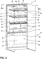
- the refrigerator 10 is shown with the first and second doors 18, 20 and freezer drawer 22 removed to reveal the refrigerator cabinet 12 and freezer cabinet 24 which are separated by a mullion 26.
- a number of shelves 28 are shown disposed in the refrigerator cabinet 12 and are contemplated to be vertically adjustable therein.
- the refrigerator cabinet 12 also includes a number of drawers 30 for storing various items, such as fresh fruits and vegetables, in specific temperature controlled environments.
- the refrigerator 10 includes an exterior wrapper 32 which includes first and second side walls 34, 36, top wall 38 and rear wall 40 ( FIG. 7A ).
- the exterior wrapper 32 is contemplated to be a metal component formed of a sheet metal material.
- the refrigerator 10 further includes a refrigerator liner 42 which includes first and second side walls 44, 46, top wall 48, rear wall 50 ( FIG. 7A ) and bottom wall 52.
- the freezer cabinet 24 also includes a freezer liner 54 having first and second side walls 56, 58 and top wall 60.
- the refrigerator liner 42 and freezer liner 54 are also contemplated to be metal components made of a sheet metal material that is bent and welded to the specifications of the refrigerator 10. As encapsulated by the exterior wrapper 32, the refrigerator liner 42 and freezer liner 54 are spaced-apart from the exterior wrapper 32 to provide an insulating space therebetween, as further described below.
- a wall covering assembly 62 includes a rear wall 64 and a top wall 66 disposed over and adjacent to the rear wall 50 ( FIG. 7A ) and top wall 48 of the refrigerator liner 42. In this way, the wall covering assembly 62 defines rearmost and uppermost parameters of the refrigerator cabinet 12 at rear wall 64 and top wall 66.
- the wall covering assembly 62 is configured to conceal cooling components of the refrigerator 10, and also conceal air distribution systems for the cooling of the refrigerator cabinet 12 and for specifically directing air flow for an air curtain system as further described below.
- the rear wall 64 of the wall covering assembly 62 is a ventilated wall having a plurality of ports 132 disposed therethrough.
- the rear wall 64 of the wall covering assembly 62 is configured to provide cooled air to the refrigerator cabinet 12 in use, as further described below.
- the duct assembly 70 is configured to be concealed by the wall covering assembly 62 as best shown in FIG. 6 .
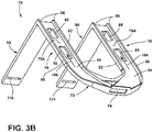
- the duct assembly 70 includes a lower portion 72 having a lower opening 74 ( FIG. 3B ) disposed therethrough.
- the lower opening 74 is configured to align with a housing for a radial fan for providing air to the duct assembly 70 as powered by the radial fan ( FIG. 6 ).
- first and second upright ducts 76, 78 define an upright portion of the duct assembly 70.
- the first and second upright ducts 76, 78 each include first and second side walls 80, 82, which are spaced-apart and interconnected by front walls 84 as best shown in FIG. 3B .
- the first and second side walls 80, 82 and front wall 84 of the first and second upright ducts 76, 78 form vertical channels 76A, 78A which open outwardly towards the rear wall 50 of the refrigerator liner 42 in assembly.
- the first and second side walls 80, 82 include outermost contact surfaces 86 which are configured to contact the rear wall 50 of the refrigerator liner 42 to substantially close off the channels 76A, 78A for channeling air upwards along the first and second upright ducts 76, 78 as powered by the radial fan.
- first and second upper ducts 90, 92 outwardly extend in a substantially horizontal manner to define a lateral portion of the duct assembly 70.
- the upper ducts 90, 92 each include first and second side walls 94, 96 which are interconnected by bottom walls 98 to form upwardly opening horizontal channels 90A, 92A, respectively.
- channels 90A, 92A, channels 90A, 92A are fluidly connected with channels 76A, 78A, respectively.
- air flow is configured to flow upward in a direction as indicated by arrows 104, 106 in vertical channels 76A, 78A, respectively, and is then directed outwardly in the directions as indicated by arrows 108, 110 along channels 90A, 92A, respectively.
- the air flows along the channels 90A, 92A towards an end wall 112 thereof, the air is directed downward through downwardly opening vents 114, 116 in the direction as indicated by arrows 118, 120 ( FIG. 3A ).
- Channels 90A, 92A are upwardly opening channels defined by first and second side walls 94, 96 which include uppermost contact surfaces 122 which are configured to be engaged with the top wall 48 of the refrigerator liner 42 ( FIG. 2 ), or other like structure, for closing off the upwardly opening channels 90A, 92A.
- the channels 90A, 92A are configured to direct air flow to the downwardly opening vents 114, 116 for providing an air curtain within the refrigerator cabinet 12 which can create an air barrier for blocking direct air flow to the gaskets of the refrigerator 10, and for keeping cold air inside the refrigerator cabinet 12, as further described below.
- the outwardly opening vertical channels 76A, 78A of the duct assembly 70 are shown with the outwardly extending upper ducts 90, 92 extending in a substantially perpendicular manner relative to the first and second lower ducts 76, 78.
- the configuration of the duct assembly 70 is configured to compliment the configuration of the wall covering assembly 62, as shown in FIG. 5 , and the refrigerator liner, as shown in FIG. 7A .
- the first and second upright ducts 76, 78 include a plurality of access apertures 85 disposed through the front wall 84 thereof.
- the access apertures 85 are configured to allow for air to pass through the upright ducts 76, 78 as air is directed in the travel pass as indicated by arrows 104 and 106. In this way, the upwardly directed air can escape through the access apertures 85 to provide cooling air to the refrigerator cabinet 12 through the ventilated rear wall 64 of the wall covering assembly 62, as further described below.
- the wall covering assembly 62 is shown having rear wall 64 and top wall 66, wherein the rear wall 64 is substantially vertical with top wall 66 extending outwardly therefrom in a substantially perpendicular or horizontal manner.
- the rear wall 64 includes a ventilated portion 130 which is a substantially planar portion having a plurality of ports 132 disposed therethrough.
- the ports 132 define venting apertures dispersed across the ventilated portion 130, such that the entire ventilated portion 130 includes a designed pattern 134 made up of the ports 132 disposed therethrough.
- the ventilated portion 130 includes an outer surface 136 and an inner surface 138.
- the top wall 66 of the wall covering assembly 62 includes an inner surface 144 and an outer surface 146.
- a front lip portion 148 is disposed at a front edge of the top wall 66 as shown in FIG. 4 .
- the top wall 66 further includes venting slots 150, 152 which are configured to align with the downwardly opening vents 114, 116 of the duct assembly 70 shown in FIGS. 3A and 3B . In this way, air channeled through the duct assembly 70 is directed downwardly through the downwardly opening vents 114, 116, in the direction indicated by arrows 118, 120 in FIG. 3A for dispersement into the refrigerator cabinet 12 through venting slots 150, 152 of the wall covering assembly 62.
- the ports 132 open outwardly into the refrigerator cabinet for cooling the refrigerator cabinet 12 with an air flow directed in a perpendicular manner emanating from the ventilated portion 130 of the wall covering assembly 62 as indicated by arrow 140.
- an air curtain (AC FIG. 5 ) will be created by the air directed downwardly through venting slots 150, 152 which will help prevent the air exiting the ports 132, indicated by arrow 140, from directly contacting the doors 18, 20 ( FIG. 1 ) of the refrigerator 10, and also from directly contacting gaskets disposed around the doors 18, 20, as further described below.
- Refrigerated air directly contacting the gaskets of the refrigerator 10 may cause condensation on outer surfaces of the gaskets, which are exposed to the ambient air of the room in which the refrigerator 10 is disposed.
- This condensation is an undesired effect of cooling the refrigerator cabinet 12, such that the present concept provides an air curtain (AC FIG. 5 ) for preventing outwardly directed cooled air along path 140 emanating from the ventilated portion of the wall covering assembly 62 from reaching the gaskets without disruption.
- AC FIG. 5 an air curtain for preventing outwardly directed cooled air along path 140 emanating from the ventilated portion of the wall covering assembly 62 from reaching the gaskets without disruption.
- the wall covering assembly 62 also includes an inclined portion 160 which generally defines a housing area 162 which is used to house and conceal components used to cool air for cooling the refrigerator cabinet 12. Such components may include fans for directing the cooled air, evaporators, condensers and other components (i.e., electrical components) of the refrigerator 10. As better shown in FIGS. 6 and 7 , the wall covering assembly 62 provides a false wall to the refrigerator cabinet 12 that is spaced-apart from the refrigerator liner 42, such that the duct assembly 70 and other components of the refrigerator 10 can also be concealed behind the false wall of wall covering assembly 62.
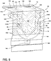
- the duct assembly 70 is shown in phantom as mounted on the wall covering assembly 62 at inner surfaces 144, 138 of the wall covering assembly 62.
- the upper ducts 90, 92 are shown disposed on the inner surface 144 of the top wall 66 of the wall covering assembly 62.
- First and second upright ducts 76, 78 are shown disposed on the rear inner surface 138 of the rear wall 64 of the wall covering assembly 62 at ventilated portion 130.
- a number of the ports 132A of ports 132 are aligned with the access apertures 85 of the first and second upright ducts 76, 78 which will provide air flow in an outward direction as indicated by arrow 140.
- An air curtain AC is defined by the downwardly directed air flowing from venting slots 150, 152 as channeled to the venting slots 150, 152 of the wall covering assembly 62 by first and second upper ducts 90, 92.
- the air curtain AC shown in FIG. 5 is substantially defined by the downward air flow indicated by arrows 118, 120 shown in FIG. 3A of the duct assembly 70. As shown in FIG.
- the air curtain AC intersects and disrupts the outward air flow 140 from ports 132A, such that the outward flow of air in the direction as indicated by arrow 140 will not directly contact the front portion of the refrigerator cabinet 12, but will instead be disrupted by the air curtain AC. In this way, a condensation effect on a gasket for the refrigerator 10 can be avoided, as further described below.
- a fan housing 164 is shown disposed at the lower portion 72 of the duct assembly 70 which is configured to house a radial fan for propelling air along the duct assembly 70 as indicated by arrows 104, 106, 108 and 110 and further downward in the direction as indicated by arrows 118, 120 ( FIG. 3A ) to create the air curtain AC.
- the fan housing 164 is disposed in the housing area 162 defined by the wall covering assembly 62 at inclined portion 160, as better shown in FIGS. 6 and 7A .
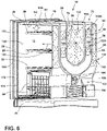
- the refrigerator 10 is shown with the exterior wrapper 32 and liner 42 removed to reveal the duct assembly 70 disposed on the wall covering assembly 62.
- the duct assembly 70 is configured to create an air curtain AC along a front portion 12A of the refrigerator cabinet 12.
- the front portion 12A of the refrigerator cabinet 12 is shown disposed adjacent to the second door 20 of the refrigerator 10 and is contemplated to provide air flow in a downward direction between the first and second doors 18, 20 and the outermost portions of the shelves 28 and drawers 30.
- the air curtain AC will intercept or otherwise disrupt the flow of air from the ports 132A of the ventilated portion 130 of the wall covering assembly 62 shown outwardly directed into the refrigerator cabinet 12 in the direction as indicated by arrow 140.
- a trim breaker 170 includes a stepped configuration having an outer rim 172 and an inner rim 174.
- the trim breaker 170 is configured to couple the exterior wrapper 32 ( FIG. 2 ) to the liner 42 ( FIG. 2 ). Specifically, the exterior wrapper 32 will couple to the outer rim 172 of the trim breaker 170, and the liner 42 will couple to the inner rim 174 of the trim breaker 170.
- a gasket 180 is positioned between the trim breaker 170 and the doors 18, 20, .
- the gasket 180 is contemplated to be coupled to the door and configured to form a seal against the front surface 14 ( FIGS. 1 and 2 ) of the refrigerator 10 and the doors 18, 20.
- the gasket 180 forms a seal against the front surface 14 of the refrigerator 10 when the first and second doors 18, 20 are in the closed position as shown in FIG. 1 .
- the air curtain AC of the present concept is provided to prevent cooled air, distributed through the ventilated portion 130 of the wall covering assembly 62, from directly contacting the gasket assembly 180.
- the gasket assembly 180 is contemplated to be a polymeric part that is in contact with the room environment outside of the refrigerator 10, as well as the cooled compartment of the refrigerator compartment 12. Air flow in the direction as indicated by arrow 140 may cause condensation to form on the outer surfaces of the gasket assembly 180 if this air flow is not disrupted by the air curtain AC of the present concept.
- the duct assembly 70 includes the upper lateral ducts 90, 92 which extend across the top wall 66 of the wall covering assembly 62 to properly position the air curtain AC at the front portion 12A of the refrigerator cabinet 12 for disrupting direct contact between the cooled air distributed through the ventilated portion 130 of the wall covering assembly 62 in the direction as indicated by arrow 140, and the gasket assembly 180.
- the gasket assembly 180 may include a number of separate gaskets used to seal the doors 18, 20 individually.
- a fan 166 is shown positioned within the fan housing 164 for providing cooled air to the duct assembly 70.
- the fan 166 is a radial fan disposed above an evaporator 168.
- the evaporator 168 is configured to provide cooled air to the housing area 162 defined between the wall covering assembly 62 and the liner 42 for dissemination of the cooled air into the refrigerator cabinet 12 via the ports 132A disposed on the ventilated portion 130 of the wall covering assembly 62.
- the fan 166 is configured to draw cooled air provided by the evaporator 168 into the duct assembly 70 for moving the cooled air in a downward direction at the air curtain AC along the front portion 12A of the refrigerator cabinet 12.
- the cooled air is not only provided by the ventilated portion 130 of the wall covering assembly 62, but is also provided by the downward air flow of the air curtain AC into the refrigerator cabinet 12.
- the fan assembly 166 is in thermal communication with the evaporator 168 and is fluidly connected to the duct assembly 70 within the housing area 162.
- the fan assembly 166 is configured to move cooled air from the evaporator 168 to the duct assembly 70 and propel the air through the upright ducts 76, 78 and upper ducts 90, 92.
- the evaporator 168 and fan assembly 166 are substantially concealed by the wall covering assembly 62 within the refrigerator cabinet 12 in assembly.
- the air curtain AC directs air flow along the front portion 12A of the refrigerator cabinet 12 which is positioned along inner surfaces of the doors 18, 20 and distal ends of the shelves 28 and drawers 30. It is further contemplated that the air curtain AC may be provided for accelerated air flow when the doors 18, 20 are opened in order to retain cooled air within the refrigerator cabinet 12 while a user keeps one or both of the doors 18, 20 in an open position. As further noted in FIG. 6 , the evaporator 168 and fan 166 are disposed within the housing area 162 created by the wall covering assembly 62.
- the wall covering assembly 62 creates a false wall disposed at both the rear portion and upper portion of the refrigerator cabinet 12 to conceal the fan 166 and evaporator 168, as well as the duct assembly 70, and other like components used to cool the refrigerator cabinet 12.
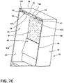
- channels 76A, 78A, 90A, 92A are outwardly opening channels which are closed off in assembly by the rear wall 50 of the refrigerator liner 42, as shown in FIG. 7B , and further closed off by top wall 48 of the refrigerator liner 42, as shown in FIG. 7C .
- the refrigerator 10 is shown with the exterior wrapper 32 disposed around the refrigerator liner 42 to create a spacing 200 therebetween, which may include a vacuum insulated space provided by vacuum ports 202.
- the refrigerator liner 42 includes a rear wall 50 that is adjacent to and spaced-apart from the rear wall 64 of the wall covering assembly 62.
- the top wall 48 of the refrigerator liner 42 is disposed adjacent to and spaced-apart from the top wall 66 of the wall covering assembly 62.
- a cavity 190 is formed between the spaced-apart portions of the refrigerator liner 42 and the wall covering assembly 62.
- the cavity 190 includes a first portion 192 that extends between the rear wall 64 of the wall covering assembly 62 and the rear wall 50 of the refrigerator liner 42. As shown in FIG. 7A , the first portion 192 of the cavity 190 houses the vertical section of the duct assembly 70, which is indicated as upright duct 76 in FIG. 7A .
- the cavity 190 further includes a second portion 194 that extends outwardly in a substantially horizontal manner relative to the first portion 192.
- the second portion 194 is configured to house the upper or lateral ducts 90, 92 ( FIG. 6 ) of the duct assembly 70, such that the duct assembly 70 can direct air for the air curtain to the front portion 12A of the refrigerator cabinet 12 in a concealed manner within the second portion 194 of the cavity 190.
- the inner and outer rim portions 172, 174 of the trim breaker 170 are shown coupled to the exterior wrapper 32 and the liner 42, respectively.
- the cross-sectional view of the refrigerator 10 shows the first portion 192 of the cavity 190 having the first and second upright ducts 76, 78 disposed therein with channels 76A, 78A, respectively.
- the rear wall 50 of the refrigerator liner 42 is shown as well as rear wall 40 of the exterior wrapper 32.
- a spacing 200 exists between the exterior wrapper 32 and the refrigerator liner 42 which may be a vacuum insulated space for insulating the refrigerator cabinet 12.
- the gasket 180 is shown on both doors 18, 20 relative to the trim breaker 170. As shown in FIG.
- channels 76A, 78A are closed by the rear wall 50 of the refrigerator liner 42 to properly channel air upward in the duct assembly 70.
- air will also be directed outwardly into the refrigerator cabinet 12 through ports 132A that align with access apertures 85 of the channel 76A, 78A, as best shown in FIG. 6 .
- the second portion 194 of the cavity 190 is shown housing the upper lateral ducts 90, 92 having channels 90A, 92A, respectively.
- the upwardly or outwardly opening channels 90A, 92A are shown closed off by a top wall 48 of the refrigerator liner 42 for properly channeling air towards the downwardly opening venting slots 150, 152 for providing the air curtain AC as shown in FIG. 5 .
- the duct assembly 70 is shown having upright duct 76 fluidly connected to upper duct 90 for providing air to downwardly opening vent 114 which is shown aligned with venting slot 150 disposed in the wall covering assembly 62. Air flow in the direction as indicated by arrow 140 is provided through ports 132A, which align with access aperture 85 in upright duct 76.
- FIG. 8A another embodiment of a wall covering assembly 210 is shown having a rear wall 212. It is contemplated that the wall covering assembly 210 will also include a top wall similar to top wall 66 shown and described above with wall covering assembly 62.
- the rear wall 212 of wall covering assembly 210 includes an upper portion 212A, a middle portion 212B and a bottom portion 212C.
- the middle portion 212B is an inclined portion which creates a housing area 214 disposed behind the rear wall 212 for housing components for cooling a refrigerator.
- the rear wall 212 includes a plurality of ports 216 disposed in a pattern 218 along the upper, middle and bottom portions 212A, 212B, 212C of the rear wall 212.
- the rear wall 212 includes a pattern 218 of ports 216 substantially covering the entirety of the rear wall 212.
- the ports 216 are contemplated to be optimally sized to sufficiently provide air in an outward direction as indicated by arrow 220 into a refrigerator cabinet, such as refrigerator cabinet 12 described above. It is contemplated that a number of the ports 216 will be aesthetic only, while other ports 216A may be aligned with access apertures disposed in a duct assembly, such as access apertures 85 shown in duct assembly 70 and described above.
- the rear wall 212 of the wall covering assembly 210 includes a ventilated portion 222 which includes a pattern 218 of ports 216 disposed substantially throughout the entirety of the rear wall 212.
- ports 216A While only ports 216A provide air flow in the direction as indicated by arrow 220 into the refrigerator cabinet, the remaining ports 216 provide the overall patterned appearance for the rear wall 212 of the wall covering assembly 210.
- the ports 216 may include round, square, or other like shaped apertures for adequately providing air flow into a refrigerator cabinet. Further, combination of variously shaped apertures may be used for the ports 216 and 216A for providing a variety of patterns 218 on the rear wall 212 of wall covering assembly 210.
- the ports 216 and 216A function in a similar manner as the ports 132, 132A described above with wall covering assembly 62.
- the rear wall 212 is a fully ventilated rear wall 212, whereas the rear wall 64 of wall covering assembly 62 included only a ventilated portion 130.
- FIG. 8B a rearview of the wall covering assembly 210 is shown with attachment features 224 disposed thereon for coupling the rear wall 212 to the inside of a refrigerator cabinet.
- the housing area 214 may include a radial fan that directly provides air flow into a refrigerator cabinet at ports 216B. Such a cooling configuration may provide a quick chill feature to the refrigerator cabinet and access through ports 216B may be selectively provided when desired by a user.
- the wall covering assembly 210 is shown disposed within the refrigerator cabinet 12.
- the wall covering assembly 210 includes a top wall 226 which is similar to top wall 66 shown and described above.
- the radial fan 166 is disposed within the radial fan housing 164 adjacent an evaporator 168 for providing cooling into the refrigerator cabinet 12.
- the top wall 226 and the rear wall 212 of the wall covering assembly 210 are disposed adjacent to the top wall 48 and rear wall 50 of the refrigerator liner 42 such that a spacing 190 is created therebetween for housing a duct assembly, such as duct assembly 70 shown and described above.
- ports 216B are disposed on the inclined portion or middle portion 212B of rear wall 212 for directly providing air into the refrigerator cabinet 12 as propelled by the radial fan 166.
- FIG. 10 another embodiment of a wall covering assembly 230 is shown having a rear wall 232 and a top wall 234.
- the wall covering assembly 230 is contemplated to be received in a refrigerator liner 42 in a manner similar to wall covering assembly 62 discussed above.
- the wall covering assembly 230 defines rearmost and uppermost parameters of the refrigerator cabinet 12 at rear wall 232 and top wall 234.
- the wall covering assembly 230 is used to conceal an air distribution system 231 in a manner similar to wall covering assembly 62 discussed above.
- the rear wall 232 is substantially vertical as disposed within refrigerator liner 42, and top wall 234 extends outwardly from the rear wall 232 in a substantially perpendicular manner. As shown in FIG.
- the rear wall 232 includes a ventilated portion 236 which is a substantially planar portion having a plurality of ports 238 disposed therethrough.
- the ports 238 define venting apertures dispersed across the ventilated portion 236, such that the entire ventilated portion 236 includes a designed pattern 240 made up of the ports 238 disposed therethrough.
- the pattern 240 of ports 238 extends across the entirety of the ventilated portion 236 between the sidewalls 44 and 46 of the refrigerator liner 42.
- the pattern 240 of ports 238 includes a first set of ports 238A that are in communication with the air distribution system 231.
- the pattern 240 of ports 238 further includes a second set of ports 238B that are in communication with a cavity similar to cavity 190 formed between the spaced-apart portions of the refrigerator liner 42 and the wall covering assembly 230, as discussed above.
- ports 238A introduce cooled air into the refrigerator cabinet 12, while ports 238B will help provide for a complete pattern 240 extending across the entire ventilated portion 236 of rear wall 232.
- the entirety of the rear wall 232 can be a ventilated portion, such as depicted on rear wall 212 of FIG. 8A discussed above.
- the top wall 234 of the wall covering assembly 230 includes a front lip portion 242 disposed at a forward most edge 244 of the top wall 234.
- the front lip portion 242 is an upwardly angled portion connecting the forward most edge 244 of the top wall 234 with the top wall 48 of the refrigerator liner 42.
- On the front lip portion 242, a number of angled venting slots 246A and 246B are disposed which are in communication with the air distribution system 231. Specifically, the angled venting slots 246A and 246B are in communication with a lateral portion of the air distribution system 231 as best described below with reference to FIG. 13 .
- the angled venting slots 246A and 246B are angled outward and downward in a direction as indicated by arrow 248. With the location of the angled venting slots 246A and 246B on the top wall 234 of wall covering assembly 230, the angled venting slots 246A and 246B are positioned at an upper portion of the refrigerator cabinet 12. This location provides the angled venting slots 246A and 246B with access to storage bins and shelves disposed on upper inner surfaces of the doors 18 and 20 ( FIG. 1 ) to cool these compartments without disruption from the air curtain, as best shown in FIG. 14 .
- the top wall 234 includes venting slots 250, 252 which are configured to align with downwardly opening vents of a duct assembly of the air distribution system 231, as best shown in FIG. 13 .
- venting slots 250, 252 are configured to align with downwardly opening vents of a duct assembly of the air distribution system 231, as best shown in FIG. 13 .
- an air curtain is formed through venting slots 250, 252 in a manner similar to air curtain AC shown and described above with reference to FIG. 5 emanating from venting slots 150, 152.
- the wall covering assembly 230 provides an air curtain from venting slots 250, 252, such that air exiting the ports 238A will be disrupted from directly contacting the inner surfaces of the doors 18, 20 ( FIG.
- the wall covering assembly 230 also includes an inwardly inclined portion 254 and a base portion 256 which generally define a housing area 258 which is used to house and conceal components used to cool air for cooling the refrigerator cabinet 12.
- Such components may include fans for directing the cooled air, evaporators, condensers and other components (i.e., electrical components) of the refrigerator 10.
- FIG. 11 rear wall 232 is shown exploded away from the refrigerator cabinet 12 to reveal a duct assembly 70A shown disposed on the rear wall 50 of the refrigerator liner 42.
- the duct assembly 70A is akin to duct assembly 70 shown and described above, such that like reference numerals are used herein to describe similar features of duct assembly 70A.
- duct assembly 70A is part of the air distribution system 231 configured to be concealed by the wall covering assembly 230, as best shown in FIG. 10 .
- the duct assembly 70A includes a lower portion 72 having a lower opening 74 ( FIG. 12 ) disposed therethrough.
- first and second upright ducts 76, 78 define an upright portion of the duct assembly 70A.
- the front walls 84 of the first and second upright ducts 76, 78 include access apertures 260 which are disposed in a complimentary pattern relative to pattern 240 of the ports 238 disposed on rear wall 232.
- the access apertures 260 are configured to align with the associated ports 238A disposed through the ventilated portion 236 of rear wall 232 to provide cooled air to the refrigerator compartment 12 through the wall covering assembly 230.
- the top wall 234 of the wall covering assembly 230 is shown exploded away from the refrigerator cabinet 12 to reveal first and second upper ducts 90, 92 of the duct assembly 70A shown disposed on the top wall 48 of the refrigerator liner 42.
- the first and second upper ducts 90, 92 outwardly extend in a substantially horizontal manner relative to the first and second upright ducts 76, 78 to define a lateral portion of the duct assembly 70A.
- Air is powered by the fan of the air distribution system 231 ( FIG. 10 ) and is directed from the first and second upright ducts 76, 78 to the first and second upper ducts 90, 92.
- the venting slots 250, 252 of the top wall 234 of the wall covering assembly 230 align with the downwardly opening vents 114, 116 disposed on the first and second upper ducts 90, 92, respectively.
- the first and second upper ducts 90, 92 include end walls 112 having the venting apertures 262A and 262B disposed thereon. End walls 112 are contemplated to be disposed at a complementary angle relative to the front lip portion 242 of top wall 234.
- venting apertures 262A and 262B of the first and second upper ducts 90, 92 align with the angled venting slots 246A and 246B disposed on front lip portion 242 of the top wall 234 of the wall covering assembly 230 to provide cooled air from the duct assembly 70A to the storage compartments or bins disposed on the inner surfaces of the doors 18, 20, as shown in FIG. 14 .
- FIG. 14 a cross-sectional view of the refrigerator compartment 12 of FIG. 10 is shown.
- the air distribution within the refrigerator compartment 12 is depicted. Specifically, cooled air emanating from the rear wall 232 of the wall covering assembly 230 is introduced into the refrigerator compartment 12 along a substantially horizontal path as indicated by arrow 270. This air is introduced through the first set of ports 238A of the rear wall 232 shown in FIG. 10 . As the cooled air flowing along the path as indicated by arrow 270 approaches the doors 18, 20 of the refrigerator 10, the cooled air is disrupted by the downwardly directed air curtain introduced into the refrigerator compartment 12 at venting slots 250, 252 of the top wall 234 along a path as indicated by arrow 272.
- door 18 includes an inner surface 176 having a plurality of storage bins 178 disposed thereon.
- the storage bins 178 are contemplated to be adjustable members that couple to the inner surface 176 of the door 18. Cooled air is directed towards the storage bins 178 along the path as indicated by arrow 274 for cooling the contents of the bins 178 in use.
- the air directed along the path indicated by arrow 274 emanates from the angled venting slots 246A and 246B disposed on front lip portion 242 of the top wall 234 of the wall covering assembly 230.
- the air flow at arrow 274 that is used to cool the contents of the storage bins 178 is uninterrupted by the downwardly directed air curtain depicted at arrow 272. It is further contemplated that the angled venting slots 246A and 246B disposed on front lip portion 242 of the top wall 234 of the wall covering assembly 230 are finely tuned to concentrate airflow on the storage bins 178 of the inner surface 176 of the door 18, and therefore do not direct air towards the gasket assembly 180 of the door 18.
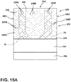
- the wall covering assembly 230 is shown having the ventilated portion 236 with a plurality of ports 238 disposed therethrough.
- the ports 238 are shown in a pattern 240A which includes a first group of ports 238A which are disposed adjacent to the first and second upright ducts 76, 78, such that ports 238A are in communication with the air distribution system 231 to introduce cooled air into the refrigerator compartment 12 in a substantially horizontal manner.
- the ports 238A shown in FIG. 15A are contemplated to be round ports having a diameter of approximately 10 mm.
- the second set of ports 238B may include round ports having a diameter of approximately 7 mm. In the embodiment shown in FIG.
- the ports 238A generally follow the contours of the first and second upright ducts 76, 78 as shown in the phantom lines provided in FIG. 15A .
- the ports 238 of the embodiment shown in FIG. 15A are arranged in a pattern 240A that covers the entirety of ventilated portion 236 of rear wall 232 between opposite ends OE1 and OE2 thereof.
- the pattern 240A includes a first set of ports 238A that are in communication with the air distribution system 231 along the first and second upright ducts 76, 78, and a second set of ports 238B which open into the refrigerator cabinet 12 on one side of the rear wall 232, and open into a cavity 190 ( FIG. 7B ) defined between the rear wall 232 of the wall covering assembly 230 and the rear wall 50 of the refrigerator liner 42 on an opposite side of the rear wall 232.
- the ports 238 are shown in a pattern 240B which includes a first group of ports 238A which are disposed adjacent to the first and second upright ducts 76, 78, such that ports 238A are in communication with the air distribution system 231 to introduce cooled air into the refrigerator compartment 12 in a substantially horizontal manner.
- the ports 238A shown in FIG. 15B are contemplated to be round ports having a diameter of approximately 13 mm.
- the second set of ports 238B may include round ports having a diameter of approximately 8 mm. While the embodiments shown in FIGS.
- 15A and 15B include mainly round ports 238, it is contemplated that other port shapes can be used having other dimensions to provide an aesthetically pleasing pattern covering, or partially covering, the ventilated portion 236 of the rear wall 232.
- the ports 238A generally follow the contours of the first and second upright ducts 76, 78 as shown in the phantom lines provided in FIG. 15B .
- the pattern 240B of ports 238 cover the entirety of ventilated portion 236 of rear wall 232 between opposite ends OE1 and OE2 thereof, however, it is contemplated that pattern 240B may cover only a portion of the ventilated portion 236 to achieve a desired aesthetic for the pattern 240B.
- the pattern 240B includes a first set of ports 238A that are in communication with the air distribution system 231 along the first and second upright ducts 76, 78, and a second set of ports 238B which open into the refrigerator cabinet 12 on one side of the rear wall 232, and open into a cavity 190 ( FIG. 14 ) defined between the rear wall 232 of the wall covering assembly 230 and the rear wall 50 of the refrigerator liner 42 on an opposite side of the rear wall 232.
- the term "coupled” in all of its forms, couple, coupling, coupled, etc. generally means the joining of two components (electrical or mechanical) directly or indirectly to one another. Such joining may be stationary in nature or movable in nature. Such joining may be achieved with the two components (electrical or mechanical) and any additional intermediate members being integrally formed as a single unitary body with one another or with the two components. Such joining may be permanent in nature or may be removable or releasable in nature unless otherwise stated.
- elements shown as integrally formed may be constructed of multiple parts or elements shown as multiple parts may be integrally formed, the operation of the interfaces may be reversed or otherwise varied, the length or width of the structures and/or members or connector or other elements of the system may be varied, the nature or number of adjustment positions provided between the elements may be varied.
- the elements and/or assemblies of the system may be constructed from any of a wide variety of materials that provide sufficient strength or durability, in any of a wide variety of colors, textures, and combinations. Accordingly, all such modifications are intended to be included within the scope of the present innovations.
Landscapes
- Engineering & Computer Science (AREA)
- General Engineering & Computer Science (AREA)
- Mechanical Engineering (AREA)
- Chemical & Material Sciences (AREA)
- Combustion & Propulsion (AREA)
- Physics & Mathematics (AREA)
- Thermal Sciences (AREA)
- Cold Air Circulating Systems And Constructional Details In Refrigerators (AREA)
Abstract
Description
- The present concept relates to a refrigeration device, and more particularly, to a refrigerator having a wall covering for concealing an air curtain system.
JP2004-061084A FR2980963A1 JP2002-168560A JP2002-295948A - One aspect of the present concept includes a refrigerator having an external wrapper and a liner disposed within the external wrapper. The liner includes a top wall, first and second sidewalls, a bottom wall and a rear wall. A wall covering assembly includes a top wall disposed adjacent to and spaced-apart from the top wall of the liner, and a rear wall disposed adjacent to and spaced-apart from the rear wall of the liner. In assembly, the liner and the wall covering assembly cooperate to define a refrigerator cabinet. A cavity is formed between the liner and the wall covering assembly and includes a first portion disposed between the rear wall of the liner and the rear wall of the wall covering assembly, and a second portion disposed between the top wall of the liner and the top wall of the wall covering assembly. A duct assembly includes an upright portion disposed in the first portion of the cavity and a lateral portion disposed in the second portion of the cavity.
- Another aspect of the present concept includes a refrigerator having a liner and a wall covering assembly. The liner includes a top wall, first and second sidewalls, a bottom wall and a rear wall. The wall covering assembly includes a top wall and a rear wall having a ventilated portion. In assembly, the wall covering assembly is spaced-apart from the liner to form a cavity therebetween. A duct assembly includes an upright portion disposed along the rear wall of the wall covering assembly. The upright portion includes one or more access apertures opening into the ventilated portion of the rear wall of the wall covering assembly to deliver cooled air to a refrigerator cabinet defined by the wall covering assembly and the liner.
- Yet another aspect of the present concept includes a refrigerator having a liner with a top wall, a rear wall, first and second sidewalls and a bottom wall. A wall covering assembly includes a top wall disposed adjacent to and spaced-apart from the top wall of the liner and a rear wall disposed adjacent to and spaced-apart from the rear wall of the liner. Together, the liner and the wall covering assembly cooperate to define a refrigerator cabinet in assembly. The rear wall of the wall covering assembly includes a ventilated portion for providing outwardly directed air to the refrigerator cabinet. A duct assembly is disposed between the wall covering assembly and the liner and is configured to deliver air to a front portion of the refrigerator cabinet to create a downwardly directed air curtain at the front portion of the refrigerator cabinet. The air curtain disrupts a flow of the outwardly directed air from the ventilated portion of the wall covering assembly at the front portion of the refrigerator cabinet.
- These and other features, advantages, and objects of the present device will be further understood and appreciated by those skilled in the art upon studying the following specification, claims, and appended drawings.
- In the drawings:
-
FIG. 1 is a front perspective view of a refrigerator according to one embodiment of the present concept; -
FIG. 2 is a front perspective view of the refrigerator ofFIG. 1 with doors and drawers removed to reveal a refrigerator cabinet and a freezer cabinet; -
FIG. 3A is a top perspective view of a duct assembly for an air curtain system; -
FIG. 3B is a bottom perspective view of the duct assembly ofFIG. 3A ; -
FIG. 4 is a top perspective view of a wall covering assembly; -
FIG. 5 is a rear perspective view of the wall covering assembly ofFIG. 4 having the duct assembly ofFIG. 3A coupled thereto; -
FIG. 6 is a rear perspective view of the refrigerator ofFIG. 2 with an exterior liner and wrapper removed therefrom to reveal the wall covering assembly and air curtain assembly of the present concept; -
FIG. 7A is a cross-sectional view of the refrigerator ofFIG. 2 take at line VIIA; -
FIG. 7B is a cross-sectional view of the refrigerator ofFIG. 1 take at line VIIB; -
FIG. 7C is a cross-sectional view of the refrigerator ofFIG. 1 take at line VIIC; -
FIG. 7D is a cross-sectional view of the refrigerator ofFIG. 1 take at line VIID; -
FIG. 8A is a front perspective view of a rear wall of a wall covering assembly according to another embodiment; -
FIG. 8B is a rear perspective view of the rear wall ofFIG. 8A ; -
FIG. 9 is a cross-sectional view of the rear wall ofFIG. 8A disposed within a refrigerator cabinet; -
FIG. 10 is a bottom perspective view of a refrigerator liner and wall covering assembly according to another embodiment; -
FIG. 11 is a top perspective view of the refrigerator liner and wall covering assembly ofFIG. 10 with a rear wall of the wall covering assembly exploded away; -
FIG. 12 is a bottom perspective view of the refrigerator liner and wall covering assembly ofFIG. 11 ; -
FIG. 13 is a bottom perspective view of the refrigerator liner and wall covering assembly ofFIG. 12 with a top wall of the wall covering assembly exploded away; -
FIG. 14 is a cross-sectional view of the refrigerator liner and wall covering assembly ofFIG. 10 taken at line XIV showing relative air distribution within a refrigerator cabinet; -
FIG. 15A is a front elevational view of a wall covering assembly according to another embodiment; and -
FIG. 15B is a front elevational view of a wall covering assembly according to another embodiment. - For purposes of description herein the terms "upper," "lower," "right," "left," "rear," "front," "vertical," "horizontal," and derivatives thereof shall relate to the device as oriented in
FIG. 1 . However, it is to be understood that the device may assume various alternative orientations and step sequences, except where expressly specified to the contrary. It is also to be understood that the specific devices and processes illustrated in the attached drawings, and described in the following specification are simply exemplary embodiments of the inventive concepts defined in the appended claims. Hence, specific dimensions and other physical characteristics relating to the embodiments disclosed herein are not to be considered as limiting, unless the claims expressly state otherwise. - Referring now to
FIG. 1 , arefrigerator 10 is shown having afront surface 14 that is generally disposed around a front opening 16 (FIG. 2 ) of a refrigerator cabinet 12 (FIG. 2 ). Therefrigerator cabinet 12 is contemplated to be an insulated space for storing fresh food items having first andsecond doors front surface 14 of therefrigerator cabinet 12 for selectively providing access to therefrigerator cabinet 12. In the embodiment shown inFIG. 1 , afreezer drawer 22 is configured to selectively provide access to a freezer cabinet 24 (FIG. 2 ) disposed below therefrigerator cabinet 12. Therefrigerator 10 shown inFIG. 1 is an exemplary embodiment of a refrigerator for use with the present concept, and is not meant to limit the scope of the present concept in any manner. - Referring now to
FIG. 2 , therefrigerator 10 is shown with the first andsecond doors freezer drawer 22 removed to reveal therefrigerator cabinet 12 andfreezer cabinet 24 which are separated by amullion 26. In the embodiment ofFIG. 2 , a number ofshelves 28 are shown disposed in therefrigerator cabinet 12 and are contemplated to be vertically adjustable therein. Therefrigerator cabinet 12 also includes a number ofdrawers 30 for storing various items, such as fresh fruits and vegetables, in specific temperature controlled environments. Therefrigerator 10 includes anexterior wrapper 32 which includes first andsecond side walls top wall 38 and rear wall 40 (FIG. 7A ). Theexterior wrapper 32 is contemplated to be a metal component formed of a sheet metal material. Therefrigerator 10 further includes arefrigerator liner 42 which includes first andsecond side walls top wall 48, rear wall 50 (FIG. 7A ) andbottom wall 52. Thefreezer cabinet 24 also includes afreezer liner 54 having first andsecond side walls top wall 60. Therefrigerator liner 42 andfreezer liner 54 are also contemplated to be metal components made of a sheet metal material that is bent and welded to the specifications of therefrigerator 10. As encapsulated by theexterior wrapper 32, therefrigerator liner 42 andfreezer liner 54 are spaced-apart from theexterior wrapper 32 to provide an insulating space therebetween, as further described below. - As further shown in
FIG. 2 , awall covering assembly 62 includes arear wall 64 and atop wall 66 disposed over and adjacent to the rear wall 50 (FIG. 7A ) andtop wall 48 of therefrigerator liner 42. In this way, thewall covering assembly 62 defines rearmost and uppermost parameters of therefrigerator cabinet 12 atrear wall 64 andtop wall 66. Thewall covering assembly 62 is configured to conceal cooling components of therefrigerator 10, and also conceal air distribution systems for the cooling of therefrigerator cabinet 12 and for specifically directing air flow for an air curtain system as further described below. As shown inFIG. 2 , therear wall 64 of thewall covering assembly 62 is a ventilated wall having a plurality ofports 132 disposed therethrough. Therear wall 64 of thewall covering assembly 62 is configured to provide cooled air to therefrigerator cabinet 12 in use, as further described below. - Referring now to
FIGS. 3A and3B , aduct assembly 70 is shown. Theduct assembly 70 is configured to be concealed by thewall covering assembly 62 as best shown inFIG. 6 . Theduct assembly 70 includes alower portion 72 having a lower opening 74 (FIG. 3B ) disposed therethrough. In assembly, thelower opening 74 is configured to align with a housing for a radial fan for providing air to theduct assembly 70 as powered by the radial fan (FIG. 6 ). Extending upwardly from thelower portion 72, first and secondupright ducts duct assembly 70. The first and secondupright ducts second side walls front walls 84 as best shown inFIG. 3B . Thus, as shown inFIG. 3B , the first andsecond side walls front wall 84 of the first and secondupright ducts vertical channels rear wall 50 of therefrigerator liner 42 in assembly. The first andsecond side walls rear wall 50 of therefrigerator liner 42 to substantially close off thechannels upright ducts upright ducts upper ducts duct assembly 70. Theupper ducts second side walls bottom walls 98 to form upwardly openinghorizontal channels rear portions channels channels channels arrows vertical channels arrows channels channels end wall 112 thereof, the air is directed downward through downwardly openingvents arrows 118, 120 (FIG. 3A ).Channels second side walls top wall 48 of the refrigerator liner 42 (FIG. 2 ), or other like structure, for closing off the upwardly openingchannels channels vents refrigerator cabinet 12 which can create an air barrier for blocking direct air flow to the gaskets of therefrigerator 10, and for keeping cold air inside therefrigerator cabinet 12, as further described below. - With further reference to
FIGS. 3A and3B , the outwardly openingvertical channels duct assembly 70 are shown with the outwardly extendingupper ducts lower ducts duct assembly 70 is configured to compliment the configuration of thewall covering assembly 62, as shown inFIG. 5 , and the refrigerator liner, as shown inFIG. 7A . As further shown inFIGS. 3A and3B , the first and secondupright ducts access apertures 85 disposed through thefront wall 84 thereof. The access apertures 85 are configured to allow for air to pass through theupright ducts arrows access apertures 85 to provide cooling air to therefrigerator cabinet 12 through the ventilatedrear wall 64 of thewall covering assembly 62, as further described below. - Referring now to
FIG. 4 , thewall covering assembly 62 is shown havingrear wall 64 andtop wall 66, wherein therear wall 64 is substantially vertical withtop wall 66 extending outwardly therefrom in a substantially perpendicular or horizontal manner. As shown inFIG. 4 , therear wall 64 includes a ventilatedportion 130 which is a substantially planar portion having a plurality ofports 132 disposed therethrough. Specifically, theports 132 define venting apertures dispersed across the ventilatedportion 130, such that the entire ventilatedportion 130 includes a designedpattern 134 made up of theports 132 disposed therethrough. The ventilatedportion 130 includes anouter surface 136 and aninner surface 138. It is theinner surface 138 of the ventilatedportion 130 that is contemplated to contact thefront wall 84 of theupright ducts duct assembly 70 shown inFIG. 3A . Further, it is contemplated that a number of the ports 132 (FIG. 5 ) of thepattern 134 will be aligned with theaccess apertures 85 of theupright ducts channels arrows FIG. 3A , but will also be directed outwardly towards therefrigerator cabinet 12 in a direction as indicated byarrow 140 inFIG. 4 from theaccess apertures 85 of theupright ducts - As further shown in
FIG. 4 , thetop wall 66 of thewall covering assembly 62 includes aninner surface 144 and anouter surface 146. Afront lip portion 148 is disposed at a front edge of thetop wall 66 as shown inFIG. 4 . Thetop wall 66 further includes ventingslots vents duct assembly 70 shown inFIGS. 3A and3B . In this way, air channeled through theduct assembly 70 is directed downwardly through the downwardly openingvents arrows FIG. 3A for dispersement into therefrigerator cabinet 12 through ventingslots wall covering assembly 62. Thus, theports 132 open outwardly into the refrigerator cabinet for cooling therefrigerator cabinet 12 with an air flow directed in a perpendicular manner emanating from the ventilatedportion 130 of thewall covering assembly 62 as indicated byarrow 140. Further, an air curtain (ACFIG. 5 ) will be created by the air directed downwardly through ventingslots ports 132, indicated byarrow 140, from directly contacting thedoors 18, 20 (FIG. 1 ) of therefrigerator 10, and also from directly contacting gaskets disposed around thedoors refrigerator 10 may cause condensation on outer surfaces of the gaskets, which are exposed to the ambient air of the room in which therefrigerator 10 is disposed. This condensation is an undesired effect of cooling therefrigerator cabinet 12, such that the present concept provides an air curtain (ACFIG. 5 ) for preventing outwardly directed cooled air alongpath 140 emanating from the ventilated portion of thewall covering assembly 62 from reaching the gaskets without disruption. - As further shown in
FIG. 4 , thewall covering assembly 62 also includes aninclined portion 160 which generally defines ahousing area 162 which is used to house and conceal components used to cool air for cooling therefrigerator cabinet 12. Such components may include fans for directing the cooled air, evaporators, condensers and other components (i.e., electrical components) of therefrigerator 10. As better shown inFIGS. 6 and7 , thewall covering assembly 62 provides a false wall to therefrigerator cabinet 12 that is spaced-apart from therefrigerator liner 42, such that theduct assembly 70 and other components of therefrigerator 10 can also be concealed behind the false wall ofwall covering assembly 62. - Referring now to
FIG. 5 , theduct assembly 70 is shown in phantom as mounted on thewall covering assembly 62 atinner surfaces wall covering assembly 62. Specifically, theupper ducts inner surface 144 of thetop wall 66 of thewall covering assembly 62. First and secondupright ducts inner surface 138 of therear wall 64 of thewall covering assembly 62 at ventilatedportion 130. As shown inFIG. 5 , a number of theports 132A ofports 132 are aligned with theaccess apertures 85 of the first and secondupright ducts arrow 140. Thus, theports 132A disposed on the ventilatedportion 130 of thewall covering assembly 62 will direct air in the direction as indicated byarrow 140 towards a front portion of therefrigerator cabinet 12. An air curtain AC is defined by the downwardly directed air flowing from ventingslots slots wall covering assembly 62 by first and secondupper ducts FIG. 5 is substantially defined by the downward air flow indicated byarrows FIG. 3A of theduct assembly 70. As shown inFIG. 5 , the air curtain AC intersects and disrupts theoutward air flow 140 fromports 132A, such that the outward flow of air in the direction as indicated byarrow 140 will not directly contact the front portion of therefrigerator cabinet 12, but will instead be disrupted by the air curtain AC. In this way, a condensation effect on a gasket for therefrigerator 10 can be avoided, as further described below. As further shown inFIG. 5 , afan housing 164 is shown disposed at thelower portion 72 of theduct assembly 70 which is configured to house a radial fan for propelling air along theduct assembly 70 as indicated byarrows arrows 118, 120 (FIG. 3A ) to create the air curtain AC. Thefan housing 164 is disposed in thehousing area 162 defined by thewall covering assembly 62 atinclined portion 160, as better shown inFIGS. 6 and7A . - Referring now to
FIG. 6 , therefrigerator 10 is shown with theexterior wrapper 32 andliner 42 removed to reveal theduct assembly 70 disposed on thewall covering assembly 62. As noted above, theduct assembly 70 is configured to create an air curtain AC along afront portion 12A of therefrigerator cabinet 12. Thefront portion 12A of therefrigerator cabinet 12 is shown disposed adjacent to thesecond door 20 of therefrigerator 10 and is contemplated to provide air flow in a downward direction between the first andsecond doors shelves 28 anddrawers 30. In this way, the air curtain AC will intercept or otherwise disrupt the flow of air from theports 132A of the ventilatedportion 130 of thewall covering assembly 62 shown outwardly directed into therefrigerator cabinet 12 in the direction as indicated byarrow 140. As specifically shown inFIG. 6 , atrim breaker 170 includes a stepped configuration having anouter rim 172 and aninner rim 174. Thetrim breaker 170 is configured to couple the exterior wrapper 32 (FIG. 2 ) to the liner 42 (FIG. 2 ). Specifically, theexterior wrapper 32 will couple to theouter rim 172 of thetrim breaker 170, and theliner 42 will couple to theinner rim 174 of thetrim breaker 170. Between thetrim breaker 170 and thedoors gasket 180 is positioned. Thegasket 180 is contemplated to be coupled to the door and configured to form a seal against the front surface 14 (FIGS. 1 and2 ) of therefrigerator 10 and thedoors gasket 180 forms a seal against thefront surface 14 of therefrigerator 10 when the first andsecond doors FIG. 1 . The air curtain AC of the present concept is provided to prevent cooled air, distributed through the ventilatedportion 130 of thewall covering assembly 62, from directly contacting thegasket assembly 180. Thegasket assembly 180 is contemplated to be a polymeric part that is in contact with the room environment outside of therefrigerator 10, as well as the cooled compartment of therefrigerator compartment 12. Air flow in the direction as indicated byarrow 140 may cause condensation to form on the outer surfaces of thegasket assembly 180 if this air flow is not disrupted by the air curtain AC of the present concept. Thus, theduct assembly 70 includes theupper lateral ducts top wall 66 of thewall covering assembly 62 to properly position the air curtain AC at thefront portion 12A of therefrigerator cabinet 12 for disrupting direct contact between the cooled air distributed through the ventilatedportion 130 of thewall covering assembly 62 in the direction as indicated byarrow 140, and thegasket assembly 180. Thegasket assembly 180 may include a number of separate gaskets used to seal thedoors - As further shown in
FIG. 6 , afan 166 is shown positioned within thefan housing 164 for providing cooled air to theduct assembly 70. In the embodiment shown inFIG. 6 , thefan 166 is a radial fan disposed above anevaporator 168. Theevaporator 168 is configured to provide cooled air to thehousing area 162 defined between thewall covering assembly 62 and theliner 42 for dissemination of the cooled air into therefrigerator cabinet 12 via theports 132A disposed on the ventilatedportion 130 of thewall covering assembly 62. Further, thefan 166 is configured to draw cooled air provided by theevaporator 168 into theduct assembly 70 for moving the cooled air in a downward direction at the air curtain AC along thefront portion 12A of therefrigerator cabinet 12. In this way, the cooled air is not only provided by the ventilatedportion 130 of thewall covering assembly 62, but is also provided by the downward air flow of the air curtain AC into therefrigerator cabinet 12. Thus, thefan assembly 166 is in thermal communication with theevaporator 168 and is fluidly connected to theduct assembly 70 within thehousing area 162. Thefan assembly 166 is configured to move cooled air from theevaporator 168 to theduct assembly 70 and propel the air through theupright ducts upper ducts evaporator 168 andfan assembly 166 are substantially concealed by thewall covering assembly 62 within therefrigerator cabinet 12 in assembly. - As noted above, the air curtain AC directs air flow along the
front portion 12A of therefrigerator cabinet 12 which is positioned along inner surfaces of thedoors shelves 28 anddrawers 30. It is further contemplated that the air curtain AC may be provided for accelerated air flow when thedoors refrigerator cabinet 12 while a user keeps one or both of thedoors FIG. 6 , theevaporator 168 andfan 166 are disposed within thehousing area 162 created by thewall covering assembly 62. In this way, thewall covering assembly 62 creates a false wall disposed at both the rear portion and upper portion of therefrigerator cabinet 12 to conceal thefan 166 andevaporator 168, as well as theduct assembly 70, and other like components used to cool therefrigerator cabinet 12. As further shown inFIG. 6 ,channels rear wall 50 of therefrigerator liner 42, as shown inFIG. 7B , and further closed off bytop wall 48 of therefrigerator liner 42, as shown inFIG. 7C . - Referring now to
FIG. 7A , therefrigerator 10 is shown with theexterior wrapper 32 disposed around therefrigerator liner 42 to create aspacing 200 therebetween, which may include a vacuum insulated space provided by vacuum ports 202. As shown inFIG. 7A , therefrigerator liner 42 includes arear wall 50 that is adjacent to and spaced-apart from therear wall 64 of thewall covering assembly 62. Similarly, thetop wall 48 of therefrigerator liner 42 is disposed adjacent to and spaced-apart from thetop wall 66 of thewall covering assembly 62. Thus, as shown inFIG. 7A , acavity 190 is formed between the spaced-apart portions of therefrigerator liner 42 and thewall covering assembly 62. Thecavity 190 includes afirst portion 192 that extends between therear wall 64 of thewall covering assembly 62 and therear wall 50 of therefrigerator liner 42. As shown inFIG. 7A , thefirst portion 192 of thecavity 190 houses the vertical section of theduct assembly 70, which is indicated asupright duct 76 inFIG. 7A . Thecavity 190 further includes asecond portion 194 that extends outwardly in a substantially horizontal manner relative to thefirst portion 192. Thesecond portion 194 is configured to house the upper orlateral ducts 90, 92 (FIG. 6 ) of theduct assembly 70, such that theduct assembly 70 can direct air for the air curtain to thefront portion 12A of therefrigerator cabinet 12 in a concealed manner within thesecond portion 194 of thecavity 190. As further shown inFIG. 7A , the inner andouter rim portions trim breaker 170 are shown coupled to theexterior wrapper 32 and theliner 42, respectively. - Referring now to
FIG. 7B , the cross-sectional view of therefrigerator 10 shows thefirst portion 192 of thecavity 190 having the first and secondupright ducts channels FIG. 7B , therear wall 50 of therefrigerator liner 42 is shown as well asrear wall 40 of theexterior wrapper 32. As noted above, aspacing 200 exists between theexterior wrapper 32 and therefrigerator liner 42 which may be a vacuum insulated space for insulating therefrigerator cabinet 12. In the embodiment shown inFIG. 7B , thegasket 180 is shown on bothdoors trim breaker 170. As shown inFIG. 7B ,channels rear wall 50 of therefrigerator liner 42 to properly channel air upward in theduct assembly 70. As noted above, air will also be directed outwardly into therefrigerator cabinet 12 throughports 132A that align withaccess apertures 85 of thechannel FIG. 6 . - Referring now to
FIG. 7C , thesecond portion 194 of thecavity 190 is shown housing theupper lateral ducts channels channels top wall 48 of therefrigerator liner 42 for properly channeling air towards the downwardlyopening venting slots FIG. 5 . - Referring now to
FIG. 7D , theduct assembly 70 is shown havingupright duct 76 fluidly connected toupper duct 90 for providing air to downwardly openingvent 114 which is shown aligned with ventingslot 150 disposed in thewall covering assembly 62. Air flow in the direction as indicated byarrow 140 is provided throughports 132A, which align withaccess aperture 85 inupright duct 76. - Referring now to
FIG. 8A , another embodiment of awall covering assembly 210 is shown having arear wall 212. It is contemplated that thewall covering assembly 210 will also include a top wall similar totop wall 66 shown and described above withwall covering assembly 62. Therear wall 212 ofwall covering assembly 210 includes anupper portion 212A, amiddle portion 212B and abottom portion 212C. Themiddle portion 212B is an inclined portion which creates ahousing area 214 disposed behind therear wall 212 for housing components for cooling a refrigerator. Therear wall 212 includes a plurality ofports 216 disposed in apattern 218 along the upper, middle andbottom portions rear wall 212. In this way, therear wall 212 includes apattern 218 ofports 216 substantially covering the entirety of therear wall 212. Theports 216 are contemplated to be optimally sized to sufficiently provide air in an outward direction as indicated byarrow 220 into a refrigerator cabinet, such asrefrigerator cabinet 12 described above. It is contemplated that a number of theports 216 will be aesthetic only, whileother ports 216A may be aligned with access apertures disposed in a duct assembly, such asaccess apertures 85 shown induct assembly 70 and described above. Thus, therear wall 212 of thewall covering assembly 210 includes a ventilatedportion 222 which includes apattern 218 ofports 216 disposed substantially throughout the entirety of therear wall 212. Whileonly ports 216A provide air flow in the direction as indicated byarrow 220 into the refrigerator cabinet, the remainingports 216 provide the overall patterned appearance for therear wall 212 of thewall covering assembly 210. Theports 216 may include round, square, or other like shaped apertures for adequately providing air flow into a refrigerator cabinet. Further, combination of variously shaped apertures may be used for theports patterns 218 on therear wall 212 ofwall covering assembly 210. Thus, theports ports wall covering assembly 62. In the embodiment shown inFIG. 8A , therear wall 212 is a fully ventilatedrear wall 212, whereas therear wall 64 ofwall covering assembly 62 included only a ventilatedportion 130. - Referring now to
FIG. 8B , a rearview of thewall covering assembly 210 is shown with attachment features 224 disposed thereon for coupling therear wall 212 to the inside of a refrigerator cabinet. With thebottom portion 212C being a ventilated portion, it is contemplated that thehousing area 214 may include a radial fan that directly provides air flow into a refrigerator cabinet atports 216B. Such a cooling configuration may provide a quick chill feature to the refrigerator cabinet and access throughports 216B may be selectively provided when desired by a user. - Referring now to
FIG. 9 , thewall covering assembly 210 is shown disposed within therefrigerator cabinet 12. Thewall covering assembly 210 includes atop wall 226 which is similar totop wall 66 shown and described above. Theradial fan 166 is disposed within theradial fan housing 164 adjacent anevaporator 168 for providing cooling into therefrigerator cabinet 12. As shown inFIG. 9 , thetop wall 226 and therear wall 212 of thewall covering assembly 210 are disposed adjacent to thetop wall 48 andrear wall 50 of therefrigerator liner 42 such that aspacing 190 is created therebetween for housing a duct assembly, such asduct assembly 70 shown and described above. In the embodiment shown inFIG. 9 ,ports 216B are disposed on the inclined portion ormiddle portion 212B ofrear wall 212 for directly providing air into therefrigerator cabinet 12 as propelled by theradial fan 166. - Referring now to
FIG. 10 , another embodiment of awall covering assembly 230 is shown having arear wall 232 and atop wall 234. Thewall covering assembly 230 is contemplated to be received in arefrigerator liner 42 in a manner similar towall covering assembly 62 discussed above. In this way, thewall covering assembly 230 defines rearmost and uppermost parameters of therefrigerator cabinet 12 atrear wall 232 andtop wall 234. Further, thewall covering assembly 230 is used to conceal anair distribution system 231 in a manner similar towall covering assembly 62 discussed above. As shown inFIG. 10 , therear wall 232 is substantially vertical as disposed withinrefrigerator liner 42, andtop wall 234 extends outwardly from therear wall 232 in a substantially perpendicular manner. As shown inFIG. 10 , therear wall 232 includes a ventilatedportion 236 which is a substantially planar portion having a plurality ofports 238 disposed therethrough. Specifically, theports 238 define venting apertures dispersed across the ventilatedportion 236, such that the entire ventilatedportion 236 includes a designedpattern 240 made up of theports 238 disposed therethrough. Thus, it is contemplated that thepattern 240 ofports 238 extends across the entirety of the ventilatedportion 236 between the sidewalls 44 and 46 of therefrigerator liner 42. Thepattern 240 ofports 238 includes a first set ofports 238A that are in communication with theair distribution system 231. Thepattern 240 ofports 238 further includes a second set ofports 238B that are in communication with a cavity similar tocavity 190 formed between the spaced-apart portions of therefrigerator liner 42 and thewall covering assembly 230, as discussed above. In use,ports 238A introduce cooled air into therefrigerator cabinet 12, whileports 238B will help provide for acomplete pattern 240 extending across the entire ventilatedportion 236 ofrear wall 232. It is further contemplated that the entirety of therear wall 232 can be a ventilated portion, such as depicted onrear wall 212 ofFIG. 8A discussed above. - As further shown in
FIG. 10 , thetop wall 234 of thewall covering assembly 230 includes afront lip portion 242 disposed at a forwardmost edge 244 of thetop wall 234. Thefront lip portion 242 is an upwardly angled portion connecting the forwardmost edge 244 of thetop wall 234 with thetop wall 48 of therefrigerator liner 42. On thefront lip portion 242, a number ofangled venting slots air distribution system 231. Specifically, theangled venting slots air distribution system 231 as best described below with reference toFIG. 13 . Theangled venting slots arrow 248. With the location of theangled venting slots top wall 234 ofwall covering assembly 230, theangled venting slots refrigerator cabinet 12. This location provides theangled venting slots doors 18 and 20 (FIG. 1 ) to cool these compartments without disruption from the air curtain, as best shown inFIG. 14 . - As further shown in
FIG. 10 , thetop wall 234 includes ventingslots air distribution system 231, as best shown inFIG. 13 . In this way, an air curtain is formed through ventingslots FIG. 5 emanating from ventingslots FIG. 10 , thewall covering assembly 230 provides an air curtain from ventingslots ports 238A will be disrupted from directly contacting the inner surfaces of thedoors 18, 20 (FIG. 1 ) of therefrigerator 10, and also from directly contacting the gasket assemblies disposed around thedoors angled venting slots doors FIG. 14 . - As further shown in
FIG. 10 , thewall covering assembly 230 also includes an inwardlyinclined portion 254 and abase portion 256 which generally define ahousing area 258 which is used to house and conceal components used to cool air for cooling therefrigerator cabinet 12. Such components may include fans for directing the cooled air, evaporators, condensers and other components (i.e., electrical components) of therefrigerator 10. - Referring now to
FIG. 11 ,rear wall 232 is shown exploded away from therefrigerator cabinet 12 to reveal aduct assembly 70A shown disposed on therear wall 50 of therefrigerator liner 42. Theduct assembly 70A is akin toduct assembly 70 shown and described above, such that like reference numerals are used herein to describe similar features ofduct assembly 70A. Much likeduct assembly 70,duct assembly 70A is part of theair distribution system 231 configured to be concealed by thewall covering assembly 230, as best shown inFIG. 10 . Theduct assembly 70A includes alower portion 72 having a lower opening 74 (FIG. 12 ) disposed therethrough. In assembly, thelower opening 74 is configured to align with a housing for a radial fan for providing air to theduct assembly 70A, such asradial fan 166 shown inFIG. 6 . Extending upwardly from thelower portion 72, and best shown inFIG. 12 , first and secondupright ducts duct assembly 70A. Thefront walls 84 of the first and secondupright ducts access apertures 260 which are disposed in a complimentary pattern relative topattern 240 of theports 238 disposed onrear wall 232. Specifically, theaccess apertures 260 are configured to align with the associatedports 238A disposed through the ventilatedportion 236 ofrear wall 232 to provide cooled air to therefrigerator compartment 12 through thewall covering assembly 230. - Referring now to
FIG. 13 , thetop wall 234 of thewall covering assembly 230 is shown exploded away from therefrigerator cabinet 12 to reveal first and secondupper ducts duct assembly 70A shown disposed on thetop wall 48 of therefrigerator liner 42. The first and secondupper ducts upright ducts duct assembly 70A. Air is powered by the fan of the air distribution system 231 (FIG. 10 ) and is directed from the first and secondupright ducts upper ducts upper ducts vents refrigerator cabinet 12 to provide an air curtain within therefrigerator cabinet 12. In assembly, the ventingslots top wall 234 of thewall covering assembly 230 align with the downwardly openingvents upper ducts upper ducts end walls 112 having the ventingapertures End walls 112 are contemplated to be disposed at a complementary angle relative to thefront lip portion 242 oftop wall 234. In assembly, the ventingapertures upper ducts angled venting slots front lip portion 242 of thetop wall 234 of thewall covering assembly 230 to provide cooled air from theduct assembly 70A to the storage compartments or bins disposed on the inner surfaces of thedoors FIG. 14 . - Referring now to
FIG. 14 , a cross-sectional view of therefrigerator compartment 12 ofFIG. 10 is shown. In this view, the air distribution within therefrigerator compartment 12 is depicted. Specifically, cooled air emanating from therear wall 232 of thewall covering assembly 230 is introduced into therefrigerator compartment 12 along a substantially horizontal path as indicated byarrow 270. This air is introduced through the first set ofports 238A of therear wall 232 shown inFIG. 10 . As the cooled air flowing along the path as indicated byarrow 270 approaches thedoors refrigerator 10, the cooled air is disrupted by the downwardly directed air curtain introduced into therefrigerator compartment 12 at ventingslots top wall 234 along a path as indicated byarrow 272. This disruption helps to keep cooled air in therefrigerator compartment 12 and further prevents cooled air from directly contactinggasket assemblies 180 of thedoors FIG. 14 ,door 18 includes aninner surface 176 having a plurality ofstorage bins 178 disposed thereon. Thestorage bins 178 are contemplated to be adjustable members that couple to theinner surface 176 of thedoor 18. Cooled air is directed towards thestorage bins 178 along the path as indicated byarrow 274 for cooling the contents of thebins 178 in use. The air directed along the path indicated byarrow 274 emanates from theangled venting slots front lip portion 242 of thetop wall 234 of thewall covering assembly 230. In this way, the air flow atarrow 274 that is used to cool the contents of thestorage bins 178 is uninterrupted by the downwardly directed air curtain depicted atarrow 272. It is further contemplated that theangled venting slots front lip portion 242 of thetop wall 234 of thewall covering assembly 230 are finely tuned to concentrate airflow on thestorage bins 178 of theinner surface 176 of thedoor 18, and therefore do not direct air towards thegasket assembly 180 of thedoor 18. - Referring now to
FIGS. 15A ,15B , thewall covering assembly 230 is shown having the ventilatedportion 236 with a plurality ofports 238 disposed therethrough. With specific reference toFIG. 15A , theports 238 are shown in apattern 240A which includes a first group ofports 238A which are disposed adjacent to the first and secondupright ducts ports 238A are in communication with theair distribution system 231 to introduce cooled air into therefrigerator compartment 12 in a substantially horizontal manner. Theports 238A shown inFIG. 15A are contemplated to be round ports having a diameter of approximately 10 mm. The second set ofports 238B may include round ports having a diameter of approximately 7 mm. In the embodiment shown inFIG. 15A , theports 238A generally follow the contours of the first and secondupright ducts FIG. 15A . Thus, theports 238 of the embodiment shown inFIG. 15A are arranged in apattern 240A that covers the entirety of ventilatedportion 236 ofrear wall 232 between opposite ends OE1 and OE2 thereof. Thepattern 240A includes a first set ofports 238A that are in communication with theair distribution system 231 along the first and secondupright ducts ports 238B which open into therefrigerator cabinet 12 on one side of therear wall 232, and open into a cavity 190 (FIG. 7B ) defined between therear wall 232 of thewall covering assembly 230 and therear wall 50 of therefrigerator liner 42 on an opposite side of therear wall 232. - With specific reference to
FIG. 15B , theports 238 are shown in apattern 240B which includes a first group ofports 238A which are disposed adjacent to the first and secondupright ducts ports 238A are in communication with theair distribution system 231 to introduce cooled air into therefrigerator compartment 12 in a substantially horizontal manner. Theports 238A shown inFIG. 15B are contemplated to be round ports having a diameter of approximately 13 mm. The second set ofports 238B may include round ports having a diameter of approximately 8 mm. While the embodiments shown inFIGS. 15A and15B include mainly roundports 238, it is contemplated that other port shapes can be used having other dimensions to provide an aesthetically pleasing pattern covering, or partially covering, the ventilatedportion 236 of therear wall 232. As further shown in the embodiment ofFIG. 15B , theports 238A generally follow the contours of the first and secondupright ducts FIG. 15B . InFIG. 15B , thepattern 240B ofports 238 cover the entirety of ventilatedportion 236 ofrear wall 232 between opposite ends OE1 and OE2 thereof, however, it is contemplated thatpattern 240B may cover only a portion of the ventilatedportion 236 to achieve a desired aesthetic for thepattern 240B. Thepattern 240B includes a first set ofports 238A that are in communication with theair distribution system 231 along the first and secondupright ducts ports 238B which open into therefrigerator cabinet 12 on one side of therear wall 232, and open into a cavity 190 (FIG. 14 ) defined between therear wall 232 of thewall covering assembly 230 and therear wall 50 of therefrigerator liner 42 on an opposite side of therear wall 232. - It will be understood by one having ordinary skill in the art that construction of the described device and other components is not limited to any specific material. Other exemplary embodiments of the device disclosed herein may be formed from a wide variety of materials, unless described otherwise herein.
- For purposes of this disclosure, the term "coupled" (in all of its forms, couple, coupling, coupled, etc.) generally means the joining of two components (electrical or mechanical) directly or indirectly to one another. Such joining may be stationary in nature or movable in nature. Such joining may be achieved with the two components (electrical or mechanical) and any additional intermediate members being integrally formed as a single unitary body with one another or with the two components. Such joining may be permanent in nature or may be removable or releasable in nature unless otherwise stated.
- It is also important to note that the construction and arrangement of the elements of the device as shown in the exemplary embodiments is illustrative only. Although only a few embodiments of the present innovations have been described in detail in this disclosure, those skilled in the art who review this disclosure will readily appreciate that many modifications are possible (e.g., variations in sizes, dimensions, structures, shapes and proportions of the various elements, values of parameters, mounting arrangements, use of materials, colors, orientations, etc.) without materially departing from the novel teachings and advantages of the subject matter recited. For example, elements shown as integrally formed may be constructed of multiple parts or elements shown as multiple parts may be integrally formed, the operation of the interfaces may be reversed or otherwise varied, the length or width of the structures and/or members or connector or other elements of the system may be varied, the nature or number of adjustment positions provided between the elements may be varied. It should be noted that the elements and/or assemblies of the system may be constructed from any of a wide variety of materials that provide sufficient strength or durability, in any of a wide variety of colors, textures, and combinations. Accordingly, all such modifications are intended to be included within the scope of the present innovations.
Claims (15)
- A refrigerator (10), comprising:a liner (42) having a top wall (48) and a rear wall (50);a wall covering assembly (62) having a top wall (66) and a rear wall (64) with a ventilated portion, wherein the wall covering assembly (62) is spaced-apart from the liner (42) to form a cavity (190) therebetween; anda duct assembly (70) including an upright portion disposed along the rear wall (64) of the wall covering assembly (62), the upright portion having one or more access apertures (85) opening into the ventilated portion (236) of the rear wall (64) of the wall covering assembly (62) to deliver cooled air to a refrigerator cabinet (12) defined by the wall covering assembly (62) and the liner (42).
- The refrigerator (10) of claim 1, wherein the upright portion of the duct assembly (70) includes first and second upright ducts (76, 78) that open outwardly towards the rear wall (50) of the liner (42), and further wherein the one or more access apertures (85) are disposed on a front wall of the first and second upright ducts (76, 78).
- The refrigerator (10) of claim 2, including first and second lateral ducts (90, 92) fluidly connected to the first and second upright ducts (76, 78), wherein the first and second lateral ducts (90, 92) open upwardly into the top wall (66) of the liner (42).
- The refrigerator (10) of claim 3, wherein the first and second lateral ducts (90, 92) include downwardly opening vents (114, 116) disposed above a front portion of the refrigerator cabinet (12) and further wherein the first and second lateral ducts (90, 92) provide an air curtain (AC) of downwardly directed air from the downwardly opening vents (114, 116) through the wall covering assembly (62).
- The refrigerator (10) of claim 4, wherein the downwardly directed air curtain (AC) disrupts a flow of the cooled air from the ventilated portion of the rear wall (64) of the wall covering assembly (62).
- The refrigerator (10) of any one of claims 1-5, comprising a pattern (240, 240A) of ports (238) extending across the entirety of the ventilated portion (236) between sidewalls (44, 46) of the refrigerator liner (42).
- The refrigerator (10) of claim 6, wherein said pattern (240) of ports (238) includes a first set of ports (238A) that are aligned with said access apertures (85), wherein in particular the first set of ports (238A) introduces cooled air into the refrigerator cabinet (12).
- The refrigerator (10) of claim 7, wherein said pattern (240, 240A) of ports (238) further includes a second set of ports (238B) that are in communication with the cavity, wherein in particular the second set of ports (238B) provides for a complete pattern (240) extending across the entire ventilated portion (236) of rear wall (232).
- A refrigerator (10), comprising:a liner (42) having a top wall (48), a rear wall (50), first and second sidewalls (44, 46) and a bottom wall (52);a wall covering assembly (62) having a top wall (66) disposed adjacent to and spaced-apart from the top wall (48) of the liner (42) and a rear wall (64) disposed adjacent to and spaced-apart from the rear wall (50) of the liner (42), wherein the liner (42) and the wall covering assembly (62) cooperate to define a refrigerator cabinet (12) and further wherein the rear wall (64) of the wall covering assembly (62) includes a ventilated portion for providing outwardly directed air to the refrigerator cabinet (12); anda duct assembly (70) disposed between the wall covering assembly (62) and the liner (42), wherein the duct assembly (70) is configured to deliver air to a front portion of the refrigerator cabinet (12) to create a downwardly directed air curtain (AC) at the front portion of the refrigerator cabinet (12), and further wherein the air curtain (AC) disrupts a flow of the outwardly directed air from the ventilated portion of the wall covering assembly (62).
- The refrigerator (10) of claim 9, wherein the duct assembly (70) includes an upright portion disposed along the rear wall (64) of the wall covering assembly (62), the upright portion including one or more access apertures opening into the ventilated portion (236) of the rear wall (64) of the wall covering assembly (62).
- The refrigerator (10) of claim 9 or claim 10, wherein the ventilated portion (236) of the rear wall (64) of the wall covering assembly (62) includes a plurality of ports (238) disposed therethrough.
- The refrigerator (10) of claim 11, wherein the plurality of ports (238) are arranged in a pattern substantially covering an entirety of the ventilated portion of the wall covering assembly (62) between the first and second sidewalls of the liner (42).
- The refrigerator (10) of claim 11 or claim 12, wherein a portion of the ports of the plurality of ports (238) disposed on the ventilated portion of the wall covering assembly (62) align with the one or more access apertures of the upright portion of the duct assembly (70) to deliver the flow of outwardly directed air from the ventilated portion of the wall covering assembly (62).
- The refrigerator (10) of any one of claims 9-13, including:an evaporator (168) disposed in a housing area (162) defined between the wall covering assembly (62) and the liner (42); anda fan assembly (166) in thermal communication with the evaporator (168) and fluidly connected to the duct assembly (70) within the housing area (162), the fan assembly (166) being configured to move cooled air from the evaporator (168) to the duct assembly (70), wherein the evaporator (168) and fan assembly (166) are substantially concealed by the wall covering assembly (62) within the refrigerator cabinet (12).
- A refrigerator (10), comprising:an external wrapper (32);a liner (42) disposed within the external wrapper (32), the liner including a top wall (48), first and second sidewalls (44, 46), a bottom wall (52) and a rear wall (50);a wall covering assembly (62) having a top wall (66) disposed adjacent to and spaced-apart from the top wall (48) of the liner (42) and a rear wall (64) disposed adjacent to and spaced-apart from the rear wall (50) of the liner (42), wherein the liner (42) and the wall covering assembly (62) cooperate to define a refrigerator cabinet (12);a cavity (190) formed between liner (42) and the wall covering assembly (62), the cavity (190) including a first portion (192) disposed between the rear wall (50) of the liner (42) and the rear wall (64) of the wall covering assembly (62), and a second portion (194) disposed between the top wall (48) of the liner (42) and the top wall (66) of the wall covering assembly (62); anda duct assembly (70) having an upright portion disposed in the first portion (192) of the cavity (190) and a lateral portion disposed in the second portion (194) of the cavity (190).
Priority Applications (1)
| Application Number | Priority Date | Filing Date | Title |
|---|---|---|---|
| EP22157115.1A EP4030128A1 (en) | 2016-08-08 | 2016-08-08 | Refrigerator with wall covering assembly |
Applications Claiming Priority (3)
| Application Number | Priority Date | Filing Date | Title |
|---|---|---|---|
| PCT/US2016/045986 WO2018030979A1 (en) | 2016-08-08 | 2016-08-08 | Wall covering assembly with ventilated portion and air curtain system |
| EP22157115.1A EP4030128A1 (en) | 2016-08-08 | 2016-08-08 | Refrigerator with wall covering assembly |
| EP16912812.1A EP3497388A4 (en) | 2016-08-08 | 2016-08-08 | Wall covering assembly with ventilated portion and air curtain system |
Related Parent Applications (1)
| Application Number | Title | Priority Date | Filing Date |
|---|---|---|---|
| EP16912812.1A Division EP3497388A4 (en) | 2016-08-08 | 2016-08-08 | Wall covering assembly with ventilated portion and air curtain system |
Publications (1)
| Publication Number | Publication Date |
|---|---|
| EP4030128A1 true EP4030128A1 (en) | 2022-07-20 |
Family
ID=61163117
Family Applications (2)
| Application Number | Title | Priority Date | Filing Date |
|---|---|---|---|
| EP16912812.1A Withdrawn EP3497388A4 (en) | 2016-08-08 | 2016-08-08 | Wall covering assembly with ventilated portion and air curtain system |
| EP22157115.1A Withdrawn EP4030128A1 (en) | 2016-08-08 | 2016-08-08 | Refrigerator with wall covering assembly |
Family Applications Before (1)
| Application Number | Title | Priority Date | Filing Date |
|---|---|---|---|
| EP16912812.1A Withdrawn EP3497388A4 (en) | 2016-08-08 | 2016-08-08 | Wall covering assembly with ventilated portion and air curtain system |
Country Status (3)
| Country | Link |
|---|---|
| US (1) | US10907889B2 (en) |
| EP (2) | EP3497388A4 (en) |
| WO (1) | WO2018030979A1 (en) |
Families Citing this family (3)
| Publication number | Priority date | Publication date | Assignee | Title |
|---|---|---|---|---|
| EP3497389B1 (en) | 2016-08-08 | 2021-05-26 | Whirlpool Corporation | Wall covering assembly with ventilation pattern and air curtain system |
| CN114076464B (en) * | 2020-08-18 | 2023-04-18 | 青岛海尔电冰箱有限公司 | Air-cooled refrigerator |
| US11384974B2 (en) * | 2020-12-14 | 2022-07-12 | Whirlpool Corporation | Refrigerator system |
Citations (4)
| Publication number | Priority date | Publication date | Assignee | Title |
|---|---|---|---|---|
| JP2002168560A (en) | 2000-11-30 | 2002-06-14 | Sanyo Electric Co Ltd | Refrigerator |
| JP2002295948A (en) | 2001-03-30 | 2002-10-09 | Fujitsu General Ltd | Electric refrigerator |
| JP2004061084A (en) | 2002-07-31 | 2004-02-26 | Sanyo Electric Co Ltd | Cold air passage controlling device |
| FR2980963A1 (en) | 2011-10-07 | 2013-04-12 | Andre Renard | Product exposure unit for refrigerating apparatus, has bent air transport pipe including two straight portions connected by elbow, where flap integral with one of straight portions covers cutout and part of wall of other straight portion |
Family Cites Families (17)
| Publication number | Priority date | Publication date | Assignee | Title |
|---|---|---|---|---|
| KR0159699B1 (en) | 1996-06-12 | 1999-01-15 | 김광호 | Refrigerator |
| KR0153496B1 (en) | 1996-06-29 | 1999-01-15 | 배순훈 | Refrigerator |
| KR0171523B1 (en) | 1996-09-25 | 1999-03-20 | 배순훈 | Cool air management apparatus of a refrigerator |
| JP3184776B2 (en) | 1997-03-14 | 2001-07-09 | 大宇電子株式會▲社▼ | Refrigerator with air curtain generator |
| US5791152A (en) | 1997-06-06 | 1998-08-11 | Daewoo Electronics Co., Ltd. | Refrigerator having a device for generating an air curtain and method for controlling an air curtain generating operation |
| US5809799A (en) | 1997-06-06 | 1998-09-22 | Daewoo Electronics Co., Ltd. | Refrigerator having a device for generating an air curtain |
| US6038880A (en) | 1997-06-06 | 2000-03-21 | Daewoo Electronics Co., Ltd. | Refrigerator having a device for generating an air curtain |
| KR19990005697A (en) * | 1997-06-30 | 1999-01-25 | 배순훈 | Freezer Cold Air Supply Unit with Cross Flow Fan |
| KR200263534Y1 (en) | 1998-10-30 | 2002-06-24 | 전주범 | An air curtain apparatus of a refrigerator |
| GB2358908B (en) | 1998-10-30 | 2003-04-16 | Daewoo Electronics Co Ltd | Air curtain generator for refrigerator |
| FR2828079B1 (en) * | 2001-08-06 | 2003-10-17 | Bonnet Neve | REFRIGERATED FURNITURE, ESPECIALLY VERTICAL FURNITURE, OF THE TYPE WITH COLD AIR CURTAINS AT THE FRONT OF THE FURNITURE |
| NZ534444A (en) | 2002-02-22 | 2006-02-24 | Multibras S | |
| WO2006032934A1 (en) | 2004-09-20 | 2006-03-30 | Enervac-Flutec Ltd | Air-curtain system for commercial open front refrigerators and display cabinets |
| DE102005057155A1 (en) * | 2005-11-30 | 2007-05-31 | BSH Bosch und Siemens Hausgeräte GmbH | A method for distributing chilled air into the chambers of a two temperature refrigeration appliance has a pivotable baffle blocking the air flow from one or other of the chambers according to a temperature sensor |
| KR100768851B1 (en) * | 2006-05-19 | 2007-10-22 | 엘지전자 주식회사 | Refrigerator |
| DE102008010520A1 (en) * | 2008-02-22 | 2009-09-03 | BSH Bosch und Siemens Hausgeräte GmbH | Refrigeration unit with circulating air cooling |
| KR101522186B1 (en) * | 2013-06-20 | 2015-05-22 | 삼성전자 주식회사 | Refrigerator |
-
2016
- 2016-08-08 EP EP16912812.1A patent/EP3497388A4/en not_active Withdrawn
- 2016-08-08 US US16/310,502 patent/US10907889B2/en active Active
- 2016-08-08 EP EP22157115.1A patent/EP4030128A1/en not_active Withdrawn
- 2016-08-08 WO PCT/US2016/045986 patent/WO2018030979A1/en not_active Ceased
Patent Citations (4)
| Publication number | Priority date | Publication date | Assignee | Title |
|---|---|---|---|---|
| JP2002168560A (en) | 2000-11-30 | 2002-06-14 | Sanyo Electric Co Ltd | Refrigerator |
| JP2002295948A (en) | 2001-03-30 | 2002-10-09 | Fujitsu General Ltd | Electric refrigerator |
| JP2004061084A (en) | 2002-07-31 | 2004-02-26 | Sanyo Electric Co Ltd | Cold air passage controlling device |
| FR2980963A1 (en) | 2011-10-07 | 2013-04-12 | Andre Renard | Product exposure unit for refrigerating apparatus, has bent air transport pipe including two straight portions connected by elbow, where flap integral with one of straight portions covers cutout and part of wall of other straight portion |
Also Published As
| Publication number | Publication date |
|---|---|
| EP3497388A4 (en) | 2020-03-25 |
| WO2018030979A1 (en) | 2018-02-15 |
| EP3497388A1 (en) | 2019-06-19 |
| US10907889B2 (en) | 2021-02-02 |
| US20190249918A1 (en) | 2019-08-15 |
Similar Documents
| Publication | Publication Date | Title |
|---|---|---|
| US12372293B2 (en) | Wall covering assembly with ventilation pattern and air curtain system | |
| US10823481B2 (en) | Refrigerator compartment with evaporator to provide cold air to ice maker | |
| US7726756B2 (en) | Refrigerator with varying width compartments and uniform width doors | |
| US5875642A (en) | Refrigerator forming an air curtain across an opening when a door is open | |
| EP2664872B1 (en) | Flat top modular cooling system with ice and air delivery | |
| US10907889B2 (en) | Wall covering assembly with ventilated portion and air curtain system | |
| EP2664876B1 (en) | Refrigerator with a modular cooling system | |
| JP4474276B2 (en) | refrigerator | |
| EP4006457B1 (en) | Refrigerator capable of improving air circulation in machine chamber | |
| JP7161891B2 (en) | refrigerator | |
| US20220378225A1 (en) | Refrigerator shelf | |
| EP1688688A1 (en) | No-frost Chest freezer | |
| JP2019095167A (en) | refrigerator | |
| CN101893361B (en) | Refrigerator | |
| CN107917574B (en) | refrigerator | |
| JP2001141355A (en) | Refrigerator | |
| JPH10243846A (en) | Freezing-refrigeration showcase | |
| JP2018105580A (en) | refrigerator | |
| WO2020114688A1 (en) | A cooling device comprising an air blowing channel | |
| JP6796754B2 (en) | refrigerator | |
| KR200148070Y1 (en) | Cold air ventilation structure of open type show case | |
| JP2016205777A (en) | refrigerator | |
| JPH11281247A (en) | refrigerator | |
| MXPA97003109A (en) | Circulation structure of cooling air for refrigeration | |
| MXPA01013085A (en) | A deflector for air currents of natural convection in refrigerators. |
Legal Events
| Date | Code | Title | Description |
|---|---|---|---|
| PUAI | Public reference made under article 153(3) epc to a published international application that has entered the european phase |
Free format text: ORIGINAL CODE: 0009012 |
|
| STAA | Information on the status of an ep patent application or granted ep patent |
Free format text: STATUS: THE APPLICATION HAS BEEN PUBLISHED |
|
| AC | Divisional application: reference to earlier application |
Ref document number: 3497388 Country of ref document: EP Kind code of ref document: P |
|
| AK | Designated contracting states |
Kind code of ref document: A1 Designated state(s): AL AT BE BG CH CY CZ DE DK EE ES FI FR GB GR HR HU IE IS IT LI LT LU LV MC MK MT NL NO PL PT RO RS SE SI SK SM TR |
|
| STAA | Information on the status of an ep patent application or granted ep patent |
Free format text: STATUS: THE APPLICATION IS DEEMED TO BE WITHDRAWN |
|
| 18D | Application deemed to be withdrawn |
Effective date: 20230121 |