EP4030068A1 - Verification cap - Google Patents
Verification cap Download PDFInfo
- Publication number
- EP4030068A1 EP4030068A1 EP22151065.4A EP22151065A EP4030068A1 EP 4030068 A1 EP4030068 A1 EP 4030068A1 EP 22151065 A EP22151065 A EP 22151065A EP 4030068 A1 EP4030068 A1 EP 4030068A1
- Authority
- EP
- European Patent Office
- Prior art keywords
- fastening clip
- verification
- verification cap
- end portion
- cap according
- Prior art date
- Legal status (The legal status is an assumption and is not a legal conclusion. Google has not performed a legal analysis and makes no representation as to the accuracy of the status listed.)
- Granted
Links
Images



Classifications
-
- F—MECHANICAL ENGINEERING; LIGHTING; HEATING; WEAPONS; BLASTING
- F16—ENGINEERING ELEMENTS AND UNITS; GENERAL MEASURES FOR PRODUCING AND MAINTAINING EFFECTIVE FUNCTIONING OF MACHINES OR INSTALLATIONS; THERMAL INSULATION IN GENERAL
- F16B—DEVICES FOR FASTENING OR SECURING CONSTRUCTIONAL ELEMENTS OR MACHINE PARTS TOGETHER, e.g. NAILS, BOLTS, CIRCLIPS, CLAMPS, CLIPS OR WEDGES; JOINTS OR JOINTING
- F16B21/00—Means for preventing relative axial movement of a pin, spigot, shaft or the like and a member surrounding it; Stud-and-socket releasable fastenings
- F16B21/06—Releasable fastening devices with snap-action
- F16B21/08—Releasable fastening devices with snap-action in which the stud, pin, or spigot has a resilient part
-
- F—MECHANICAL ENGINEERING; LIGHTING; HEATING; WEAPONS; BLASTING
- F16—ENGINEERING ELEMENTS AND UNITS; GENERAL MEASURES FOR PRODUCING AND MAINTAINING EFFECTIVE FUNCTIONING OF MACHINES OR INSTALLATIONS; THERMAL INSULATION IN GENERAL
- F16B—DEVICES FOR FASTENING OR SECURING CONSTRUCTIONAL ELEMENTS OR MACHINE PARTS TOGETHER, e.g. NAILS, BOLTS, CIRCLIPS, CLAMPS, CLIPS OR WEDGES; JOINTS OR JOINTING
- F16B45/00—Hooks; Eyes
- F16B45/002—Eyes
-
- F—MECHANICAL ENGINEERING; LIGHTING; HEATING; WEAPONS; BLASTING
- F16—ENGINEERING ELEMENTS AND UNITS; GENERAL MEASURES FOR PRODUCING AND MAINTAINING EFFECTIVE FUNCTIONING OF MACHINES OR INSTALLATIONS; THERMAL INSULATION IN GENERAL
- F16B—DEVICES FOR FASTENING OR SECURING CONSTRUCTIONAL ELEMENTS OR MACHINE PARTS TOGETHER, e.g. NAILS, BOLTS, CIRCLIPS, CLAMPS, CLIPS OR WEDGES; JOINTS OR JOINTING
- F16B2200/00—Constructional details of connections not covered for in other groups of this subclass
- F16B2200/95—Constructional details of connections not covered for in other groups of this subclass with markings, colours, indicators or the like
Definitions
- the invention relates generally to a verification cap.
- the invention relates to a verification cap, for verifying installation of a fastening clip into a support structure.
- the invention also relates to a verification cap assembly including a verification cap and a fastening clip.
- fastening clips are used to mount components, structures or panels to the frame of a vehicle.
- One particular type of fastening clip for use in a storage compartment of a vehicle is embedded to a base panel or a side panel of the storage compartment.
- Such a fastening clip is located at a fixed point, or more often, multiple fixed points, of the storage compartment.
- the fastening clip(s) is connected to a luggage ring, onto which loose objects such as shopping bags or items are attached so that they do not move around the storage compartment when the vehicle is in motion.
- Other types of fastening clips are also known within the automotive industry.
- a number of fastening clips are assembled into the storage compartment using fasteners, which can be a time-consuming process.
- the vehicle undergoes an inspection to check the quality of the fittings. This involves verifying that all of the fastening clips are installed properly. For example, the torque data recorded by electronic screwdrivers when installing the screwed luggage ring is used to verify correct installation. From this, it is understandable that having to carry and use a tool in order to install a luggage ring can be rather cumbersome, especially when access to the vehicle location is difficult. Also, since there are typically many fastening clips installed, the process for checking the quality of the fittings can be time-consuming and tedious.
- fastening clips are placed in hard-to-reach locations.
- fastening clips are placed within these hard-to-reach locations in order to prevent any objects attached to the fastening clips from moving around during transport.
- some storage compartments of vehicles have fastening clips connected to luggage rings placed at a location close to the rear passenger seats. It is particularly important to ensure that the fastening clips are properly installed in order to avoid vibrations when the vehicle is running.
- a verification cap for verifying installation of a fastening clip to a support structure, comprising:
- the correct (i.e. complete) installation of a fastening clip to a support structure can be quickly and efficiently verified.
- the provision of at least one stop member projecting away from the cover member provides a restricted space of a predetermined size that accommodates at least one component of the fastening clip.
- the cover member When the cover member is in the closed position, the at least one component of the fastening clip is accommodated within the space, to provide verification that the fastening clip is properly installed. If, however, the fastener clip is not properly installed, the space does not provide sufficient room to accommodate the at least one component of the fastening clip, and therefore the cover member is placed into an open position, disengaged from the top end part of the base member.
- the position of the cover member relative to the base member indicates whether or not, respectively, a fastening clip is fully installed to a support structure.
- This verification cap can therefore provide a visual indication of whether the fastening clip is properly installed, removing the need for tedious and time-consuming inspection processes.
- the interior space is configured to retainingly receive a head portion of the fastening clip, during assembly.
- the stop member is configured to contactingly engage with the at least one component when the at least one component is not entirely contained within the predetermined restricted space of the base member.
- the stop member comprises a latch at a distal end configured to catchingly engage with an aperture of the fastening clip when in the closed position.
- the base member comprises two opposing parallelly arranged pairs of teeth adapted to retainingly couple with a head portion of the fastening clip.
- the teeth extend from the side wall into the interior space and up towards the top end portion.
- the teeth comprise a latch portion configured to engage with the head portion of the fastening clip.
- the cover member comprises a lock member projecting away from the cover member
- the base member comprises a respective catch member configured to lockingly engage with the lock member when the cover member is in the closed position.
- the catch member is further adapted to selectively disengage from the lock member.
- the verification cap comprises two parallelly arranged stop members, spaced apart from one another at a distance corresponding to a distance between two respective components of the fastening clip.
- the at least one component is a bearing surface of an elastically deformable biasing member of the fastening clip, the bearing surface extending in a direction substantially parallel to a flat upper surface of the head portion of the fastening clip.
- the base member comprises a skirt portion projecting laterally outwardly from the bottom end portion and adapted to provide a seal between the verification cap and the support structure, during use.
- a verification cap assembly comprising a fastening clip and a verification cap.
- the fastening clip is for installation to at least one support structure, and has a body portion and a head portion.
- the verification cap is adapted to enclosingly receive the fastening clip when fastened to the at least one support structure.
- the fastening clip further comprises a pivotably movable ring member operably arranged outside the verification cap.
- the ring member is operably coupled to and forming a friction fit with the head portion of the fastening clip.
- the terms 'connected', 'attached', 'coupled', 'mounted' are intended to include direct connections between two members without any other members interposed therebetween, as well as, indirect connections between members in which one or more other members are interposed therebetween.
- the terminology includes the words specifically mentioned above, derivatives thereof, and words of similar import.
- a luggage ring assembly 10 including a fastening clip 100 having a body (104, Figure 2 ) which secures a luggage ring 20 in a way that allows the luggage ring 20 to be pivoted relative to fastening clip 100.
- the assembly 10 also includes a verification cap 200 provided with an upper lid 202 and a lower base 204.
- the lid 202 is connected together with the base 204 by a hinge 208 which allows the lid 202 to pivot about the base 204 between open and closed position.
- the base 204 has an outer side wall that defines an interior space of a predetermined depth.
- the side wall is formed as a single part having two pairs of opposing wall portions.
- the ends of the base 204 at the top and at the bottom are open, so that the outer side wall of the base 204 forms a tubular structure.
- the side wall of the base 204 has a square profile when viewed from the top.
- the base 204 may have a different profile other than a square, such as a circle or polygon, for example.
- the lid 202 is provided with an outer side wall with a profile corresponding to the profile of the base 204.
- the outer side wall of the lid 202 is formed as a single part having two pairs of opposing wall portions.
- the bottom end of the lid 202 side wall is open, having a square profile when viewed from the bottom.
- the top end of the lid 202 is closed.
- the lid 202 and the base 204 are shaped such that when they are closed together about the hinge 208, they form an enclosure which is closed at the top, and open at the bottom.
- the bottom of the base 204 is open in order to receive a head (102, Figure 2 ) of the fastening clip 100 within the interior space of the base 204.
- a skirt 206 is integrally formed on a lower part of the base 204, laterally protruding in a direction perpendicular to the side wall.
- the skirt 206 provides sealing properties when the assembly 10 is inserted into a support structure. Additionally, or alternatively, the skirt 206 is configured to cover any gaps between the trim or vehicle surface and the lower base 204 (e.g.
- the skirt 206 is continuous around the entire bottom edge of the base 204.
- the side walls of the lid 202 and base 204 each have a semi-circular cut-out (i.e. opening) on opposite wall portions, so that when the lid 202 and base 204 come together into a closed position, a circular opening is formed on opposite wall portions where the semi-circular cut-outs are formed.
- the circular opening is sized to house a section of the luggage ring 20 when the luggage ring 20 is secured to the fastening clip 100.
- a hook 210 projects downward from the lower surface of the lid 202, between the first verification tab 214 and the edge of the lid 202. As best shown in Figure 5(b) , the hook 210 is integrally formed with the first verification tab 214.
- the base 204 is provided with a catch (212, Figure 9(C) ) at a location corresponding to the hook 210 when the lid 202 is in a closed position relative to the base 204.
- the first verification tab 214 is provided with a latch at a distal end away from the lid 202.
- the hook 210 extends laterally in a direction parallel to the lower surface of the lid 202.
- the latch of the first verification tab 214 extends laterally in a direction opposite to the direction of the hook 210.
- the fastening clip 100 will be described in more detail with reference to Figures 2 and 3 , with a luggage ring 20 shown in an upstanding position.
- the body 104 of the fastening clip 100 is integrally formed with a head 102.
- the head 102 has an opening on its top surface, on which are provided mechanical stops 114 on opposite sides. These mechanical stops 114 act as a guide to secure the luggage ring 20 to the fastening clip 100 (best shown in Figure 7 ).
- the head 102 of the fastening clip 100 has holding arms 112 integral with and extending from opposite corners. The holding arms 112 are in contact with and partially surround the luggage ring 20 when the luggage ring 20 is secured to the fastening clip 100.
- the body 104 of the fastening clip 100 is provided with openings on the sides. The openings provide access for parts of the fastening clip 100 to extend through from the inside of the body 104 through to the outside. More specifically, the fastening clip 100 is provided with a pair of oppositely protruding resilient arms 110 extending through a respective pair of opposite upper openings in the body 104. The resilient arms 110 laterally protrude in a direction parallel to an upper surface of the head 102. The fastening clip 100 is also provided with a pair of oppositely protruding shoulders 108 extending through a respective pair of opposite lower openings in the body 104.
- the resilient arm 110 and shoulder 108 on each side are integrally formed, as best shown in Figure 7 .
- the fastening clip 100 is provided with legs 106 for inserting into a panel structure, in order to secure the fastening clip 100 to the support structure.
- the legs 106 of the fastening clip 100 are placed, from the top, downwards through the base 204 when the lid 202 is hinged open relative to the base 204.
- the head 102 of the fastening clip 100 is positioned in the interior space of the base 204.
- two opposing pairs of teeth 218 are parallelly arranged and extending inwards and upwards from the base 204 sidewall.
- the distal ends of the teeth 218, away from the side wall, are provided with a latch for securing the head 102 of the fastening clip in place when the fastening clip 100 is placed within the verification cap 200.
- the top surface of the head 102 is flat, so that it can easily be engaged by a digit of a user to push the fastening clip 100 downwards.
- the luggage ring 20 is held in place by the semi-circular cut-out of the base 204.
- the lid 202 and the base 204 are disengaged from one another at their respective lower and upper surfaces, but they remain connected by the hinge 208.
- the lid 202 is movable relative to the base 204 between an open position and a closed position.
- the open position the bottom end of the lid 202 side wall is disengaged from the top end of the base 204 side wall.
- the closed position the bottom end of the lid 202 side wall is engaged with the top end of the base 204 side wall.
- An example of the lid 202 in an open position is shown in Figure 5(a) , where the lid 202 is angled 45 degrees relative to the base 204.
- An example of the lid 202 in a closed position is shown in Figure 5(b) , where the lid 202 is arranged perpendicular to the base 204.
- the angle of the luggage ring 20 relative to the base 204 can vary depending on the required application.
- the luggage ring 20 is shown to be raised, offset relative to the base 204 by 45 degrees.
- the luggage ring is 20 is lowered (i.e. 0 degrees) relative to the base 204.
- Other angles are also envisaged.
- the luggage ring 20 once the luggage ring 20 has been placed into the desired position, it remains in that position since the holding arms 112 of the fastener clip 100 surround and hold the luggage ring 20 in place by friction. At the same time, the head 102 of the fastening clip 100 secures the luggage ring 20 by friction.
- the insertion of the fastening clip 100 and verification cap 200 assembly into a panel 30 is illustrated in Figure 6 .
- the legs 106 of the fastening clip 100 are inserted through an opening 32 of a panel 30.
- the top surface of the head 102 can be engaged by a digit of a user to push the fastening clip 100 downwards.
- the bottom end of the base 204 side wall has a skirt 206 that covers the opening 32 of the panel 30 from view and provides sealing between the verification cap 200 and panel 30 when the fastening clip 100 is inserted.
- the skirt 206 prevents dust and water from entering into the opening 32 of the panel 30 and into the fastening clip 100.
- the shoulders 108 and the arms 110 are elastic and resiliently biased outwards.
- the reference numeral 108 denotes the position of the shoulders before they are deformed inwardly by the force exerted.
- the reference numeral 108' denotes the position of the shoulders after deformation.
- the deformation of the shoulders 108 causes the resilient arms 110 to also deform inwards.
- the reference numeral 110 denotes the position of the arms before deformation caused by the deformation of the shoulders 108.
- the reference numeral 110 denotes the position of the arms after deformation.
- the fastening clip 100 can fit through the opening 32 of the panel 30.
- force is no longer exerted onto these components by the panel 30.
- the arms 110 and the shoulders 108 bias back outwards beyond the width of the opening 32, holding the fastening clip 100 in place, preventing removal.
- the verification cap 200 is able to verify whether a fastening clip 100 is fully (i.e. completely and properly) installed into a panel 30. After the fastening clip 100 has been secured to the panel 30, the verification cap 200 is also held in place since it is held by the fastening clip 100. In addition, the latch of the first verification tab 214 is held within an opening of the fastening clip 100 head 102 to secure the verification cap 200 in place.
- the resilient arms 110 and the shoulders 108 move completely past the opening 32 of the panel 30, and bias back outwards to their original position, to secure the fastening clip 100 in place.
- the resilient arms 110 are placed into a position laterally extending in a direction parallel to the panel 30. Since the resilient arms 110 occupy relatively little space, they can be accommodated within the predetermined space between the distal end of the verification tabs 214,216 and the base 204.
- the lid 202 of the verification cap 200 to be placed into the closed position without the verification tabs 214,216 coming into contact with the resilient arms 110.
- the top end of the base 204 side wall is in contact with the bottom end of the lid 202 side wall.
- the hook 210 of the lid 202 engages with a corresponding catch 212 of the base 204, to secure the lid 202 relative to the base 204. It is envisaged that this securement of the lid 202 to the base 204 may be releasable, so that the 202 lid and base 204 can be selectively engaged and disengaged with one another.
- the resilient arms 110 and the shoulders 108 do not move completely past the opening 32 of the panel 30, as shown in Figures 9(b)-(d) . As such, they remain in an inwardly deformed position due to a force exerted by the panel 30 onto the fastening clip 100.
- the inward bias of the shoulders 108 urges the resilient arms 110 inwards and upwards such that the resilient arms 110 come into contact with the verifications tabs 214, 216. This contact urges the lid 202 upward into an open position where the bottom of the lid 202 is disengaged with the top of the base 204.
- This provides a visual indication in a quick and simple manner that the fastening clip 100 is not properly or correctly installed into the panel 30.
- One or both of the resilient arms 110 may contact the corresponding verification tab 214,216 to urge the lid 202 upwards into an open position, indicating that the fastening clip 100 is not fully or properly installed.
- Figure 10 shows an alternative embodiment of the verification cap 300 of the present invention.
- the skirt 306 has been designed around the base 304 that is particularly adapted to eliminate, or at least minimise, any gapping between the base 304 of the cap 300 and the vehicle panel 30 (e.g. from a carpet in the trim).
- the skirt 306 comprises mechanical stops 310 for the luggage ring 20 adapted to prevent the luggage ring 20 from contacting the panel or trim (e.g. avoid rattling during movement).
- the stops 310 e.g. in the form of a ramp feature extending laterally outward from a centre portion of the skirt 306) allow for the luggage ring to be positioned at an angle with respect to the panel surface making it easier for the user to grab and pivot the luggage ring 20 during use.
- the ramp features of the stops 310 may be an integral part of the skirt 306 but may also be installed retrospectively.
- the predetermined spaces may be provided at the upper lid (e.g. through apertures or recesses within the interior surface of the upper lid) wherein verification tab(s) of a predetermined length are provided on an upper surface of the fastening clip, such that, when closing the upper lid, the verification tab(s) move into the apertures or recesses without contacting the inner surface of the lid when the fastening clip is installed correctly.
- the verification tab(s) on the fastening clip will contactingly engage with the inner surface of the upper lid, preventing the lid to be closed.
Landscapes
- Engineering & Computer Science (AREA)
- General Engineering & Computer Science (AREA)
- Mechanical Engineering (AREA)
- Insertion Pins And Rivets (AREA)
- Dairy Products (AREA)
Abstract
Description
- The invention relates generally to a verification cap. In particular, the invention relates to a verification cap, for verifying installation of a fastening clip into a support structure. The invention also relates to a verification cap assembly including a verification cap and a fastening clip.
- In the automotive industry, fastening clips are used to mount components, structures or panels to the frame of a vehicle. One particular type of fastening clip for use in a storage compartment of a vehicle, is embedded to a base panel or a side panel of the storage compartment. Such a fastening clip is located at a fixed point, or more often, multiple fixed points, of the storage compartment. The fastening clip(s) is connected to a luggage ring, onto which loose objects such as shopping bags or items are attached so that they do not move around the storage compartment when the vehicle is in motion. Other types of fastening clips are also known within the automotive industry.
- Typically, in an automotive manufacturing process, a number of fastening clips are assembled into the storage compartment using fasteners, which can be a time-consuming process. When all of the fastening clips and respective luggage rings are installed, the vehicle undergoes an inspection to check the quality of the fittings. This involves verifying that all of the fastening clips are installed properly. For example, the torque data recorded by electronic screwdrivers when installing the screwed luggage ring is used to verify correct installation. From this, it is understandable that having to carry and use a tool in order to install a luggage ring can be rather cumbersome, especially when access to the vehicle location is difficult. Also, since there are typically many fastening clips installed, the process for checking the quality of the fittings can be time-consuming and tedious. The process for quality checking is especially tedious when the fastening clips are placed in hard-to-reach locations. Often, fastening clips are placed within these hard-to-reach locations in order to prevent any objects attached to the fastening clips from moving around during transport. For example, some storage compartments of vehicles have fastening clips connected to luggage rings placed at a location close to the rear passenger seats. It is particularly important to ensure that the fastening clips are properly installed in order to avoid vibrations when the vehicle is running.
- It would be desirable to provide a verification cap that can alleviate or mitigate one or more of the aforementioned problems. Particularly, it is an object of the invention to provide a verification cap that facilitates a quick and efficient way of verifying installation of a fastening clip to a support structure. More specifically, it is an object of the invention to provide a verification cap that can quickly verify whether a fastening clip is properly installed into a support structure. It is another object of the invention to provide a verification cap that can allow an installer to efficiently verify installation of a fastening clip to a support structure by visual inspection only, which removes the need for tedious and unnecessarily involved inspection processes.
- In accordance with the present invention there is provided a verification cap according to the appended claims.
- According to an aspect of the present invention, there is provided a verification cap for verifying installation of a fastening clip to a support structure, comprising:
- a tubular base member, comprising an enclosing side wall defining an interior space between an open bottom end portion and an open top end portion, configured to retainingly receive at least a portion of the fastening clip during assembly, and
- a cover member, hingeably connected to the base member and movable between a closed position, lockingly engaged with the top end portion of the side wall, and an open position, disengaged from the top end portion of the side wall, comprising at least one stop member projecting away from the cover member into the interior space so as to define a predetermined restricted space for accommodating at least one component of the fastening clip between the bottom end portion and a distal end of the stop member when the cover member is in the closed position, during use.
- Thus, the correct (i.e. complete) installation of a fastening clip to a support structure can be quickly and efficiently verified. The provision of at least one stop member projecting away from the cover member provides a restricted space of a predetermined size that accommodates at least one component of the fastening clip. When the cover member is in the closed position, the at least one component of the fastening clip is accommodated within the space, to provide verification that the fastening clip is properly installed. If, however, the fastener clip is not properly installed, the space does not provide sufficient room to accommodate the at least one component of the fastening clip, and therefore the cover member is placed into an open position, disengaged from the top end part of the base member. The position of the cover member relative to the base member, in either a closed position or an open position, indicates whether or not, respectively, a fastening clip is fully installed to a support structure. This verification cap can therefore provide a visual indication of whether the fastening clip is properly installed, removing the need for tedious and time-consuming inspection processes.
- Advantageously, in some embodiments, the interior space is configured to retainingly receive a head portion of the fastening clip, during assembly.
- Advantageously, in some embodiments, the stop member is configured to contactingly engage with the at least one component when the at least one component is not entirely contained within the predetermined restricted space of the base member.
- Advantageously, in specific embodiments, the stop member comprises a latch at a distal end configured to catchingly engage with an aperture of the fastening clip when in the closed position.
- Advantageously, in some embodiments, the base member comprises two opposing parallelly arranged pairs of teeth adapted to retainingly couple with a head portion of the fastening clip.
- Advantageously, in some specific embodiments, the teeth extend from the side wall into the interior space and up towards the top end portion.
- Advantageously, in some embodiments, the teeth comprise a latch portion configured to engage with the head portion of the fastening clip.
- Advantageously, in some embodiments, the cover member comprises a lock member projecting away from the cover member, and the base member comprises a respective catch member configured to lockingly engage with the lock member when the cover member is in the closed position.
- Advantageously, in some specific embodiments, the catch member is further adapted to selectively disengage from the lock member.
- Advantageously, in some embodiments, the verification cap comprises two parallelly arranged stop members, spaced apart from one another at a distance corresponding to a distance between two respective components of the fastening clip.
- Advantageously, in some specific embodiments, the at least one component is a bearing surface of an elastically deformable biasing member of the fastening clip, the bearing surface extending in a direction substantially parallel to a flat upper surface of the head portion of the fastening clip.
- Advantageously, in some embodiments, the base member comprises a skirt portion projecting laterally outwardly from the bottom end portion and adapted to provide a seal between the verification cap and the support structure, during use.
- Accordingly to another aspect of the present invention, there is provided a verification cap assembly, comprising a fastening clip and a verification cap. The fastening clip is for installation to at least one support structure, and has a body portion and a head portion. The verification cap is adapted to enclosingly receive the fastening clip when fastened to the at least one support structure.
- Advantageously, in some embodiments, the fastening clip further comprises a pivotably movable ring member operably arranged outside the verification cap.
- Advantageously, in some embodiments, the ring member is operably coupled to and forming a friction fit with the head portion of the fastening clip.
- Embodiments of the invention are now described, by way of example only, hereinafter with reference to the accompanying drawings, in which:
- Figure 1
- illustrates a perspective view of a verification cap assembly including a verification cap, a fastening clip and additionally, a luggage ring secured to the fastening clip;
- Figure 2
- illustrates a perspective view of a fastening clip and luggage ring assembled together;
- Figure 3
- illustrates (a) a side view, and (b) a front view of the fastening clip and luggage ring assembly of
Figure 2 ; - Figure 4
- illustrates a perspective view of a verification cap assembly with a fastening clip (a) separated from the verification cap, and (b) assembled in the verification cap;
- Figure 5
- illustrates a perspective view of a verification cap assembly, showing a luggage ring and verification cap in (a) an open position with a raised luggage ring, and (b) a closed position with a lowered luggage ring;
- Figure 6
- illustrates a perspective view of a verification cap assembly that is (a) separate from a panel structure, and (b) installed into a panel structure;
- Figure 7
- illustrates a section view of the fastening clip and luggage ring assembly through A-A of
Figure 3(b) , showing the assembly installed into a support structure; - Figure 8
- illustrates a section view of a verification cap assembly in a closed position, having a fastening clip fully (i.e. correctly) installed into a support structure;
- Figure 9
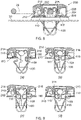
- illustrates a schematic side section view of a verification cap assembly in (a) a closed position with the lid engaged together with the base, and (b-d) an open position with the lid disengaged from the base, and
- Figure 10
- illustrates a (a) side view and (b) a top view, as well as, (c) a perspective view of an alternative embodiment of the verification cap assembly in closed position.
- Certain terminology is used in the following description for convenience only and is not limiting. The words 'right', 'left', 'lower', 'upper', 'front', 'rear', 'upward', 'down' and 'downward' designate directions in the drawings to which reference is made and are with respect to the described component when assembled and mounted. The words 'inner', 'inwardly' and 'outer', 'outwardly' refer to directions toward and away from, respectively, a designated centreline or a geometric centre of an element being described (e.g. central axis), the particular meaning being readily apparent from the context of the description.
- Further, as used herein, the terms 'connected', 'attached', 'coupled', 'mounted' are intended to include direct connections between two members without any other members interposed therebetween, as well as, indirect connections between members in which one or more other members are interposed therebetween. The terminology includes the words specifically mentioned above, derivatives thereof, and words of similar import.
- Further, unless otherwise specified, the use of ordinal adjectives, such as, "first", "second", "third" etc. merely indicate that different instances of like objects are being referred to and are not intended to imply that the objects so described must be in a given sequence, either temporally, spatially, in ranking or in any other manner.
- Like reference numerals are used to depict like features throughout.
- Referring now to
Figure 1 , there is shown aluggage ring assembly 10 including afastening clip 100 having a body (104,Figure 2 ) which secures aluggage ring 20 in a way that allows theluggage ring 20 to be pivoted relative tofastening clip 100. Theassembly 10 also includes averification cap 200 provided with anupper lid 202 and alower base 204. Thelid 202 is connected together with the base 204 by ahinge 208 which allows thelid 202 to pivot about the base 204 between open and closed position. Thebase 204 has an outer side wall that defines an interior space of a predetermined depth. The side wall is formed as a single part having two pairs of opposing wall portions. The ends of the base 204 at the top and at the bottom are open, so that the outer side wall of the base 204 forms a tubular structure. In this example embodiment, the side wall of thebase 204 has a square profile when viewed from the top. However, it is envisaged that the base 204 may have a different profile other than a square, such as a circle or polygon, for example. Thelid 202 is provided with an outer side wall with a profile corresponding to the profile of thebase 204. The outer side wall of thelid 202 is formed as a single part having two pairs of opposing wall portions. The bottom end of thelid 202 side wall is open, having a square profile when viewed from the bottom. The top end of thelid 202 is closed. Thelid 202 and the base 204 are shaped such that when they are closed together about thehinge 208, they form an enclosure which is closed at the top, and open at the bottom. The bottom of thebase 204 is open in order to receive a head (102,Figure 2 ) of thefastening clip 100 within the interior space of thebase 204. Askirt 206 is integrally formed on a lower part of thebase 204, laterally protruding in a direction perpendicular to the side wall. Theskirt 206 provides sealing properties when theassembly 10 is inserted into a support structure. Additionally, or alternatively, theskirt 206 is configured to cover any gaps between the trim or vehicle surface and the lower base 204 (e.g. due to tolerances) (see, for example, the alternative design of theverification cap 300 shown inFigure 10 ). Theskirt 206 is continuous around the entire bottom edge of thebase 204. In this example embodiment, the side walls of thelid 202 andbase 204 each have a semi-circular cut-out (i.e. opening) on opposite wall portions, so that when thelid 202 andbase 204 come together into a closed position, a circular opening is formed on opposite wall portions where the semi-circular cut-outs are formed. The circular opening is sized to house a section of theluggage ring 20 when theluggage ring 20 is secured to thefastening clip 100. - Projecting from a lower surface of the
lid 202 are afirst verification tab 214 and asecond verification tab 216. Thesecond verification tab 216 is spaced apart from thefirst verification tab 214 along the bottom surface of thelid 202. Although two verification tabs 214,216 are provided in this specific example embodiment, other embodiments may include a different number of verification tabs, for example one, three, four, or more. Ahook 210 projects downward from the lower surface of thelid 202, between thefirst verification tab 214 and the edge of thelid 202. As best shown inFigure 5(b) , thehook 210 is integrally formed with thefirst verification tab 214. Thebase 204 is provided with a catch (212,Figure 9(C) ) at a location corresponding to thehook 210 when thelid 202 is in a closed position relative to thebase 204. Thefirst verification tab 214 is provided with a latch at a distal end away from thelid 202. Thehook 210 extends laterally in a direction parallel to the lower surface of thelid 202. The latch of thefirst verification tab 214 extends laterally in a direction opposite to the direction of thehook 210. - The
fastening clip 100 will be described in more detail with reference toFigures 2 and 3 , with aluggage ring 20 shown in an upstanding position. Thebody 104 of thefastening clip 100 is integrally formed with ahead 102. Thehead 102 has an opening on its top surface, on which are providedmechanical stops 114 on opposite sides. Thesemechanical stops 114 act as a guide to secure theluggage ring 20 to the fastening clip 100 (best shown inFigure 7 ). Thehead 102 of thefastening clip 100 has holdingarms 112 integral with and extending from opposite corners. The holdingarms 112 are in contact with and partially surround theluggage ring 20 when theluggage ring 20 is secured to thefastening clip 100. This allows theluggage ring 20 to be maintained in a desired position by friction during use, such as in the upstanding position shown inFigure 2 . Thebody 104 of thefastening clip 100 is provided with openings on the sides. The openings provide access for parts of thefastening clip 100 to extend through from the inside of thebody 104 through to the outside. More specifically, thefastening clip 100 is provided with a pair of oppositely protrudingresilient arms 110 extending through a respective pair of opposite upper openings in thebody 104. Theresilient arms 110 laterally protrude in a direction parallel to an upper surface of thehead 102. Thefastening clip 100 is also provided with a pair of oppositelyprotruding shoulders 108 extending through a respective pair of opposite lower openings in thebody 104. Theresilient arm 110 andshoulder 108 on each side are integrally formed, as best shown inFigure 7 . At an end away from thehead 102, thefastening clip 100 is provided withlegs 106 for inserting into a panel structure, in order to secure thefastening clip 100 to the support structure. - Turning to
Figures 4 and 5 , to assemble thefastening clip 100 with theverification cap 200, thelegs 106 of thefastening clip 100 are placed, from the top, downwards through the base 204 when thelid 202 is hinged open relative to thebase 204. When thelegs 106 are placed through thebase 204, thehead 102 of thefastening clip 100 is positioned in the interior space of thebase 204. As best seen inFigure 4(a) , two opposing pairs ofteeth 218 are parallelly arranged and extending inwards and upwards from the base 204 sidewall. The distal ends of theteeth 218, away from the side wall, are provided with a latch for securing thehead 102 of the fastening clip in place when thefastening clip 100 is placed within theverification cap 200. The top surface of thehead 102 is flat, so that it can easily be engaged by a digit of a user to push thefastening clip 100 downwards. At the same time, theluggage ring 20 is held in place by the semi-circular cut-out of thebase 204. In the open postion, thelid 202 and the base 204 are disengaged from one another at their respective lower and upper surfaces, but they remain connected by thehinge 208. Since thelid 202 and the base 204 are connected together by ahinge 208, thelid 202 is movable relative to the base 204 between an open position and a closed position. In the open position, the bottom end of thelid 202 side wall is disengaged from the top end of the base 204 side wall. In the closed position, the bottom end of thelid 202 side wall is engaged with the top end of the base 204 side wall. An example of thelid 202 in an open position is shown inFigure 5(a) , where thelid 202 is angled 45 degrees relative to thebase 204. An example of thelid 202 in a closed position is shown inFigure 5(b) , where thelid 202 is arranged perpendicular to thebase 204. Other orientations of thelid 202 with different angles are envisaged. Similarly, the angle of theluggage ring 20 relative to the base 204 can vary depending on the required application. InFigure 5(a) , theluggage ring 20 is shown to be raised, offset relative to thebase 204 by 45 degrees. InFigure 5(b) , the luggage ring is 20 is lowered (i.e. 0 degrees) relative to thebase 204. Other angles are also envisaged. In this example embodiment, once theluggage ring 20 has been placed into the desired position, it remains in that position since the holdingarms 112 of thefastener clip 100 surround and hold theluggage ring 20 in place by friction. At the same time, thehead 102 of thefastening clip 100 secures theluggage ring 20 by friction. - The insertion of the
fastening clip 100 andverification cap 200 assembly into apanel 30 is illustrated inFigure 6 . Thelegs 106 of thefastening clip 100 are inserted through anopening 32 of apanel 30. For example, the top surface of thehead 102 can be engaged by a digit of a user to push thefastening clip 100 downwards. In this example embodiment, the bottom end of the base 204 side wall has askirt 206 that covers theopening 32 of thepanel 30 from view and provides sealing between theverification cap 200 andpanel 30 when thefastening clip 100 is inserted. Theskirt 206 prevents dust and water from entering into theopening 32 of thepanel 30 and into thefastening clip 100. In order to hold thefastening clip 100 into place inside thepanel 30, theshoulders 108 and thearms 110 are elastic and resiliently biased outwards. When thelegs 106 of thefastening clip 100 are inserted into thepanel opening 32, a force is exerted onto theshoulders 108 andarms 110 to urge them inwards, as indicated by the position denoted by the dashed line inFigure 7 . Thereference numeral 108 denotes the position of the shoulders before they are deformed inwardly by the force exerted. The reference numeral 108' denotes the position of the shoulders after deformation. The deformation of theshoulders 108 causes theresilient arms 110 to also deform inwards. Thereference numeral 110 denotes the position of the arms before deformation caused by the deformation of theshoulders 108. Thereference numeral 110 denotes the position of the arms after deformation. When theshoulders 108 andresilient arms 110 deform inwardly, thefastening clip 100 can fit through theopening 32 of thepanel 30. After theresilient arms 110 andshoulders 108 are inserted through and clear theopening 32 of thepanel 30, force is no longer exerted onto these components by thepanel 30. Thearms 110 and theshoulders 108 bias back outwards beyond the width of theopening 32, holding thefastening clip 100 in place, preventing removal. - The use of the
verification cap 200 for verifying installation of afastening clip 100 will now be described with reference toFigures 8 and 9 . Theverification cap 200 is able to verify whether afastening clip 100 is fully (i.e. completely and properly) installed into apanel 30. After thefastening clip 100 has been secured to thepanel 30, theverification cap 200 is also held in place since it is held by thefastening clip 100. In addition, the latch of thefirst verification tab 214 is held within an opening of thefastening clip 100head 102 to secure theverification cap 200 in place. - As shown in
Figure 8 and 9(a) , when thefastening clip 100 is properly or correctly installed, theresilient arms 110 and theshoulders 108 move completely past theopening 32 of thepanel 30, and bias back outwards to their original position, to secure thefastening clip 100 in place. This positions theresilient arms 110 in a way that occupies relatively little space towards the verification tabs 214,216. In this particular example embodiment, theresilient arms 110 are placed into a position laterally extending in a direction parallel to thepanel 30. Since theresilient arms 110 occupy relatively little space, they can be accommodated within the predetermined space between the distal end of the verification tabs 214,216 and thebase 204. This allows thelid 202 of theverification cap 200 to be placed into the closed position without the verification tabs 214,216 coming into contact with theresilient arms 110. When theverification cap 200 is in the closed position, the top end of the base 204 side wall is in contact with the bottom end of thelid 202 side wall. Also, in the closed position, thehook 210 of thelid 202 engages with acorresponding catch 212 of thebase 204, to secure thelid 202 relative to thebase 204. It is envisaged that this securement of thelid 202 to the base 204 may be releasable, so that the 202 lid andbase 204 can be selectively engaged and disengaged with one another. - If the
fastening clip 100 is not properly or correctly installed, then theresilient arms 110 and theshoulders 108 do not move completely past theopening 32 of thepanel 30, as shown inFigures 9(b)-(d) . As such, they remain in an inwardly deformed position due to a force exerted by thepanel 30 onto thefastening clip 100. In this example embodiment, the inward bias of theshoulders 108 urges theresilient arms 110 inwards and upwards such that theresilient arms 110 come into contact with theverifications tabs lid 202 upward into an open position where the bottom of thelid 202 is disengaged with the top of thebase 204. This provides a visual indication in a quick and simple manner that thefastening clip 100 is not properly or correctly installed into thepanel 30. One or both of theresilient arms 110 may contact the corresponding verification tab 214,216 to urge thelid 202 upwards into an open position, indicating that thefastening clip 100 is not fully or properly installed. -
Figure 10 shows an alternative embodiment of theverification cap 300 of the present invention. Here, theskirt 306 has been designed around the base 304 that is particularly adapted to eliminate, or at least minimise, any gapping between the base 304 of thecap 300 and the vehicle panel 30 (e.g. from a carpet in the trim). In addition, theskirt 306 comprisesmechanical stops 310 for theluggage ring 20 adapted to prevent theluggage ring 20 from contacting the panel or trim (e.g. avoid rattling during movement). Further, the stops 310 (e.g. in the form of a ramp feature extending laterally outward from a centre portion of the skirt 306) allow for the luggage ring to be positioned at an angle with respect to the panel surface making it easier for the user to grab and pivot theluggage ring 20 during use. The ramp features of thestops 310 may be an integral part of theskirt 306 but may also be installed retrospectively. - In yet another alternative embodiment of the verification cap of the luggage ring assembly of the present invention (not shown), the predetermined spaces may be provided at the upper lid (e.g. through apertures or recesses within the interior surface of the upper lid) wherein verification tab(s) of a predetermined length are provided on an upper surface of the fastening clip, such that, when closing the upper lid, the verification tab(s) move into the apertures or recesses without contacting the inner surface of the lid when the fastening clip is installed correctly. In the event the fastening clip is not properly inserted, the verification tab(s) on the fastening clip will contactingly engage with the inner surface of the upper lid, preventing the lid to be closed.
- It will be appreciated by persons skilled in the art that the above detailed examples have been described by way of example only and not in any limitative sense, and that various alterations and modifications are possible without departing from the scope of the invention as defined by the appended claims. Various modifications to the detailed examples described above are possible.
- Through the description and claims of this specification, the words "comprise" and "contain" and variations of them mean "including but not limited to", and they are not intended to (and do not) exclude other moieties, additives, components, integers or steps. Throughout the description and claims of this specification, the singular encompasses the plural unless the context otherwise requires. In particular, where the indefinite article is used, the specification is to be understood as contemplating plurality as well as singularity, unless the context requires otherwise.
- Features, integers, characteristics, compounds, chemical moieties or groups described in conjunction with a particular aspect, embodiment or example of the invention are to be understood to be applicable to any other aspect, embodiment or example described herein unless incompatible therewith. All of the features disclosed in this specification (including any accompanying claims, abstract and drawings), and/or all of the steps of any method or process so disclosed, may be combined in any combination, except combinations where at least some of such features and/or steps are mutually exclusive. The invention is not restricted to the details of any foregoing embodiments. The invention extends to any novel one, or any novel combination, of the features disclosed in this specification (including any accompanying claims, abstract or drawings), or to any novel one, or any novel combination, of the steps of any method or process so disclosed.
- It will be appreciated by persons skilled in the art that the above embodiment(s) have been described by way of example only and not in any limitative sense, and that various alterations and modifications are possible without departing from the scope of the invention as defined by the appended claims. Various modifications to the detailed designs as described above are possible.
Component list and reference numerals: 10 Luggage ring assembly 300 Alternative verification cap 20 Luggage ring 306 Alternative skirt 30 Panel 310 Luggage ring stops 32 Opening 100 Fastening clip 102 Head 104 Body 106 Leg 108 Shoulder (before deformation) 108' Shoulder (after deformation) 110 Resilient arm (before deformation) 110' Resilient arm (after deformation) 112 Holding arm 114 Mechanical stop 200 Verification cap 202 Lid 204 Base 206 Skirt 208 Hinge 210 Hook 212 Catch 214 First verification tab 216 Second verification tab 218 Teeth
Claims (15)
- A verification cap for verifying installation of a fastening clip to a support structure, comprising:a tubular base member, comprising an enclosing side wall defining an interior space between an open bottom end portion and an open top end portion, configured to retainingly receive at least a portion of the fastening clip during assembly, anda cover member, hingeably connected to said base member and movable between a closed position, lockingly engaged with said top end portion of said side wall, and an open position, disengaged from said top end portion of said side wall, comprising at least one stop member projecting away from said cover member into said interior space so as to define a predetermined restricted space for accommodating at least one component of the fastening clip between said bottom end portion and a distal end of said stop member when said cover member is in said closed position, during use.
- A verification cap according to claim 1, wherein said interior space is configured to retainingly receive a head portion of the fastening clip, during assembly.
- A verification cap according to any one of claims 1 and 2, wherein said stop member is configured to contactingly engage with the at least one component when the at least one component is not entirely contained within said predetermined restricted space of said base member.
- A verification cap according to any one of the preceding claims, wherein said stop member comprises a latch at a distal end configured to catchingly engage with an aperture of the fastening clip when in said closed position.
- A verification cap according to any one of the preceding claims, wherein said base member comprises two opposing parallelly arranged pairs of teeth adapted to retainingly couple with a head portion of the fastening clip.
- A verification cap according to claim 5, wherein said teeth extend from said side wall into said interior space and up towards said top end portion.
- A verification cap according to claim 5 or claim 6, wherein said teeth comprise a latch portion configured to engage with the head portion of the fastening clip.
- A verification cap according to any one of the preceding claims, wherein said cover member comprises a lock member projecting away from said cover member, and said base member comprises a respective catch member configured to lockingly engage with said lock member when said cover member is in said closed position.
- A verification cap according to claim 8, wherein said catch member is further adapted to selectively disengage from said lock member.
- A verification cap according to any one of the preceding claims, comprising two parallelly arranged stop members, spaced apart from one another at a distance corresponding to a distance between two respective components of the fastening clip.
- A verification cap according to any one of the preceding claims, wherein the at least one component is a bearing surface of an elastically deformable biasing member of the fastening clip, the bearing surface extending in a direction substantially parallel to a flat upper surface of the head portion of the fastening clip.
- A verification cap according to any one of the preceding claims, wherein said base member comprises a skirt portion projecting laterally outwardly from said bottom end portion and adapted to provide a seal between said verification cap and the support structure, during use.
- A verification cap assembly, comprising:a fastening clip for installation to at least one support structure, having a body portion and a head portion, anda verification cap according to any one of claims 1 to 12, adapted to enclosingly receive said fastening clip when fastened to the at least one support structure.
- A verification cap assembly according to claim 13, wherein said fastening clip further comprises a pivotably movable ring member operably arranged outside said verification cap.
- A verification cap assembly according to claim 14, wherein said ring member is operably coupled to and forming a friction fit with said head portion of said fastening clip.
Priority Applications (1)
| Application Number | Priority Date | Filing Date | Title |
|---|---|---|---|
| CN202210050502.XA CN114802006A (en) | 2021-01-18 | 2022-01-17 | Verification cap |
Applications Claiming Priority (1)
| Application Number | Priority Date | Filing Date | Title |
|---|---|---|---|
| ES202130025U ES1263682Y (en) | 2021-01-11 | 2021-01-11 | Tabletop portioning cheese slicer machine |
Publications (2)
| Publication Number | Publication Date |
|---|---|
| EP4030068A1 true EP4030068A1 (en) | 2022-07-20 |
| EP4030068B1 EP4030068B1 (en) | 2024-12-04 |
Family
ID=75109016
Family Applications (1)
| Application Number | Title | Priority Date | Filing Date |
|---|---|---|---|
| EP22151065.4A Active EP4030068B1 (en) | 2021-01-18 | 2022-01-11 | Verification cap |
Country Status (2)
| Country | Link |
|---|---|
| EP (1) | EP4030068B1 (en) |
| ES (1) | ES1263682Y (en) |
Citations (1)
| Publication number | Priority date | Publication date | Assignee | Title |
|---|---|---|---|---|
| EP2700828A1 (en) * | 2011-04-18 | 2014-02-26 | Nifco Inc. | Fastener |
Family Cites Families (1)
| Publication number | Priority date | Publication date | Assignee | Title |
|---|---|---|---|---|
| US6381806B1 (en) * | 2001-01-12 | 2002-05-07 | Nifty Products, Inc. | Retainer assembly for positive retention of floor mat |
-
2021
- 2021-01-11 ES ES202130025U patent/ES1263682Y/en not_active Expired - Fee Related
-
2022
- 2022-01-11 EP EP22151065.4A patent/EP4030068B1/en active Active
Patent Citations (1)
| Publication number | Priority date | Publication date | Assignee | Title |
|---|---|---|---|---|
| EP2700828A1 (en) * | 2011-04-18 | 2014-02-26 | Nifco Inc. | Fastener |
Also Published As
| Publication number | Publication date |
|---|---|
| ES1263682U (en) | 2021-03-25 |
| EP4030068B1 (en) | 2024-12-04 |
| ES1263682Y (en) | 2021-06-15 |
Similar Documents
| Publication | Publication Date | Title |
|---|---|---|
| US5354093A (en) | Air bag module having integral cover attachment | |
| US5513934A (en) | Fastener for truck bed liner | |
| US8458862B2 (en) | Locked base trim clip | |
| CN107524360B (en) | Shockproof fastener and vehicle actuator fastening device with shockproof fastener | |
| JPH0662718U (en) | Protector for wire harness | |
| KR101551025B1 (en) | Fastener for vehicle | |
| CN117791347A (en) | Switchgear | |
| KR20190094220A (en) | Fastener assembly | |
| EP4030068B1 (en) | Verification cap | |
| EP3444485B1 (en) | Fastener and fastening arrangement | |
| US5301917A (en) | Brake line isolator | |
| CN113696831B (en) | Elastic clip | |
| WO2012151403A1 (en) | An assembly for mounting a handle on a vehicle door | |
| JP4099644B2 (en) | Front bumper mounting structure | |
| CN114802006A (en) | Verification cap | |
| JP7028806B2 (en) | Striker for use in latch assemblies | |
| EP1568897B1 (en) | One part receptacle for a fastener | |
| JPH08107617A (en) | Cover locking structure | |
| JP5313631B2 (en) | Interior member mounting structure | |
| EP4015845A1 (en) | A fastener assembly | |
| US12512619B2 (en) | Hingeless peel back automotive connector cover | |
| EP4279752A1 (en) | Rfid verification cap | |
| US11059427B2 (en) | Storage box latch with a remotely located mechanical push button | |
| CN111152704B (en) | Holding structure and mounting method thereof | |
| US7631909B2 (en) | Crowned striker mounting plate |
Legal Events
| Date | Code | Title | Description |
|---|---|---|---|
| PUAI | Public reference made under article 153(3) epc to a published international application that has entered the european phase |
Free format text: ORIGINAL CODE: 0009012 |
|
| STAA | Information on the status of an ep patent application or granted ep patent |
Free format text: STATUS: THE APPLICATION HAS BEEN PUBLISHED |
|
| AK | Designated contracting states |
Kind code of ref document: A1 Designated state(s): AL AT BE BG CH CY CZ DE DK EE ES FI FR GB GR HR HU IE IS IT LI LT LU LV MC MK MT NL NO PL PT RO RS SE SI SK SM TR |
|
| STAA | Information on the status of an ep patent application or granted ep patent |
Free format text: STATUS: REQUEST FOR EXAMINATION WAS MADE |
|
| 17P | Request for examination filed |
Effective date: 20230116 |
|
| RBV | Designated contracting states (corrected) |
Designated state(s): AL AT BE BG CH CY CZ DE DK EE ES FI FR GB GR HR HU IE IS IT LI LT LU LV MC MK MT NL NO PL PT RO RS SE SI SK SM TR |
|
| STAA | Information on the status of an ep patent application or granted ep patent |
Free format text: STATUS: EXAMINATION IS IN PROGRESS |
|
| 17Q | First examination report despatched |
Effective date: 20230606 |
|
| GRAP | Despatch of communication of intention to grant a patent |
Free format text: ORIGINAL CODE: EPIDOSNIGR1 |
|
| STAA | Information on the status of an ep patent application or granted ep patent |
Free format text: STATUS: GRANT OF PATENT IS INTENDED |
|
| INTG | Intention to grant announced |
Effective date: 20240827 |
|
| RAP3 | Party data changed (applicant data changed or rights of an application transferred) |
Owner name: ILLINOIS TOOL WORKS INC. |
|
| GRAS | Grant fee paid |
Free format text: ORIGINAL CODE: EPIDOSNIGR3 |
|
| GRAA | (expected) grant |
Free format text: ORIGINAL CODE: 0009210 |
|
| STAA | Information on the status of an ep patent application or granted ep patent |
Free format text: STATUS: THE PATENT HAS BEEN GRANTED |
|
| P01 | Opt-out of the competence of the unified patent court (upc) registered |
Free format text: CASE NUMBER: APP_54482/2024 Effective date: 20241002 |
|
| AK | Designated contracting states |
Kind code of ref document: B1 Designated state(s): AL AT BE BG CH CY CZ DE DK EE ES FI FR GB GR HR HU IE IS IT LI LT LU LV MC MK MT NL NO PL PT RO RS SE SI SK SM TR |
|
| REG | Reference to a national code |
Ref country code: CH Ref legal event code: EP |
|
| REG | Reference to a national code |
Ref country code: DE Ref legal event code: R096 Ref document number: 602022008259 Country of ref document: DE |
|
| REG | Reference to a national code |
Ref country code: IE Ref legal event code: FG4D |
|
| REG | Reference to a national code |
Ref country code: LT Ref legal event code: MG9D |
|
| REG | Reference to a national code |
Ref country code: NL Ref legal event code: MP Effective date: 20241204 |
|
| PG25 | Lapsed in a contracting state [announced via postgrant information from national office to epo] |
Ref country code: HR Free format text: LAPSE BECAUSE OF FAILURE TO SUBMIT A TRANSLATION OF THE DESCRIPTION OR TO PAY THE FEE WITHIN THE PRESCRIBED TIME-LIMIT Effective date: 20241204 |
|
| PG25 | Lapsed in a contracting state [announced via postgrant information from national office to epo] |
Ref country code: FI Free format text: LAPSE BECAUSE OF FAILURE TO SUBMIT A TRANSLATION OF THE DESCRIPTION OR TO PAY THE FEE WITHIN THE PRESCRIBED TIME-LIMIT Effective date: 20241204 |
|
| PG25 | Lapsed in a contracting state [announced via postgrant information from national office to epo] |
Ref country code: BG Free format text: LAPSE BECAUSE OF FAILURE TO SUBMIT A TRANSLATION OF THE DESCRIPTION OR TO PAY THE FEE WITHIN THE PRESCRIBED TIME-LIMIT Effective date: 20241204 |
|
| PG25 | Lapsed in a contracting state [announced via postgrant information from national office to epo] |
Ref country code: ES Free format text: LAPSE BECAUSE OF FAILURE TO SUBMIT A TRANSLATION OF THE DESCRIPTION OR TO PAY THE FEE WITHIN THE PRESCRIBED TIME-LIMIT Effective date: 20241204 |
|
| PG25 | Lapsed in a contracting state [announced via postgrant information from national office to epo] |
Ref country code: NO Free format text: LAPSE BECAUSE OF FAILURE TO SUBMIT A TRANSLATION OF THE DESCRIPTION OR TO PAY THE FEE WITHIN THE PRESCRIBED TIME-LIMIT Effective date: 20250304 |
|
| PG25 | Lapsed in a contracting state [announced via postgrant information from national office to epo] |
Ref country code: LV Free format text: LAPSE BECAUSE OF FAILURE TO SUBMIT A TRANSLATION OF THE DESCRIPTION OR TO PAY THE FEE WITHIN THE PRESCRIBED TIME-LIMIT Effective date: 20241204 Ref country code: GR Free format text: LAPSE BECAUSE OF FAILURE TO SUBMIT A TRANSLATION OF THE DESCRIPTION OR TO PAY THE FEE WITHIN THE PRESCRIBED TIME-LIMIT Effective date: 20250305 |
|
| PG25 | Lapsed in a contracting state [announced via postgrant information from national office to epo] |
Ref country code: RS Free format text: LAPSE BECAUSE OF FAILURE TO SUBMIT A TRANSLATION OF THE DESCRIPTION OR TO PAY THE FEE WITHIN THE PRESCRIBED TIME-LIMIT Effective date: 20250304 |
|
| PG25 | Lapsed in a contracting state [announced via postgrant information from national office to epo] |
Ref country code: NL Free format text: LAPSE BECAUSE OF FAILURE TO SUBMIT A TRANSLATION OF THE DESCRIPTION OR TO PAY THE FEE WITHIN THE PRESCRIBED TIME-LIMIT Effective date: 20241204 |
|
| REG | Reference to a national code |
Ref country code: AT Ref legal event code: MK05 Ref document number: 1748443 Country of ref document: AT Kind code of ref document: T Effective date: 20241204 |
|
| PG25 | Lapsed in a contracting state [announced via postgrant information from national office to epo] |
Ref country code: SM Free format text: LAPSE BECAUSE OF FAILURE TO SUBMIT A TRANSLATION OF THE DESCRIPTION OR TO PAY THE FEE WITHIN THE PRESCRIBED TIME-LIMIT Effective date: 20241204 |
|
| PG25 | Lapsed in a contracting state [announced via postgrant information from national office to epo] |
Ref country code: PL Free format text: LAPSE BECAUSE OF FAILURE TO SUBMIT A TRANSLATION OF THE DESCRIPTION OR TO PAY THE FEE WITHIN THE PRESCRIBED TIME-LIMIT Effective date: 20241204 |
|
| PG25 | Lapsed in a contracting state [announced via postgrant information from national office to epo] |
Ref country code: IS Free format text: LAPSE BECAUSE OF FAILURE TO SUBMIT A TRANSLATION OF THE DESCRIPTION OR TO PAY THE FEE WITHIN THE PRESCRIBED TIME-LIMIT Effective date: 20250404 |
|
| PG25 | Lapsed in a contracting state [announced via postgrant information from national office to epo] |
Ref country code: PT Free format text: LAPSE BECAUSE OF FAILURE TO SUBMIT A TRANSLATION OF THE DESCRIPTION OR TO PAY THE FEE WITHIN THE PRESCRIBED TIME-LIMIT Effective date: 20250404 |
|
| PG25 | Lapsed in a contracting state [announced via postgrant information from national office to epo] |
Ref country code: EE Free format text: LAPSE BECAUSE OF FAILURE TO SUBMIT A TRANSLATION OF THE DESCRIPTION OR TO PAY THE FEE WITHIN THE PRESCRIBED TIME-LIMIT Effective date: 20241204 |
|
| PG25 | Lapsed in a contracting state [announced via postgrant information from national office to epo] |
Ref country code: AT Free format text: LAPSE BECAUSE OF FAILURE TO SUBMIT A TRANSLATION OF THE DESCRIPTION OR TO PAY THE FEE WITHIN THE PRESCRIBED TIME-LIMIT Effective date: 20241204 Ref country code: RO Free format text: LAPSE BECAUSE OF FAILURE TO SUBMIT A TRANSLATION OF THE DESCRIPTION OR TO PAY THE FEE WITHIN THE PRESCRIBED TIME-LIMIT Effective date: 20241204 |
|
| PG25 | Lapsed in a contracting state [announced via postgrant information from national office to epo] |
Ref country code: SK Free format text: LAPSE BECAUSE OF FAILURE TO SUBMIT A TRANSLATION OF THE DESCRIPTION OR TO PAY THE FEE WITHIN THE PRESCRIBED TIME-LIMIT Effective date: 20241204 |
|
| PG25 | Lapsed in a contracting state [announced via postgrant information from national office to epo] |
Ref country code: CZ Free format text: LAPSE BECAUSE OF FAILURE TO SUBMIT A TRANSLATION OF THE DESCRIPTION OR TO PAY THE FEE WITHIN THE PRESCRIBED TIME-LIMIT Effective date: 20241204 |
|
| PG25 | Lapsed in a contracting state [announced via postgrant information from national office to epo] |
Ref country code: IT Free format text: LAPSE BECAUSE OF FAILURE TO SUBMIT A TRANSLATION OF THE DESCRIPTION OR TO PAY THE FEE WITHIN THE PRESCRIBED TIME-LIMIT Effective date: 20241204 |
|
| REG | Reference to a national code |
Ref country code: CH Ref legal event code: PL |
|
| REG | Reference to a national code |
Ref country code: DE Ref legal event code: R097 Ref document number: 602022008259 Country of ref document: DE |
|
| PG25 | Lapsed in a contracting state [announced via postgrant information from national office to epo] |
Ref country code: SE Free format text: LAPSE BECAUSE OF FAILURE TO SUBMIT A TRANSLATION OF THE DESCRIPTION OR TO PAY THE FEE WITHIN THE PRESCRIBED TIME-LIMIT Effective date: 20241204 |
|
| PG25 | Lapsed in a contracting state [announced via postgrant information from national office to epo] |
Ref country code: MC Free format text: LAPSE BECAUSE OF FAILURE TO SUBMIT A TRANSLATION OF THE DESCRIPTION OR TO PAY THE FEE WITHIN THE PRESCRIBED TIME-LIMIT Effective date: 20241204 Ref country code: LU Free format text: LAPSE BECAUSE OF NON-PAYMENT OF DUE FEES Effective date: 20250111 |
|
| PG25 | Lapsed in a contracting state [announced via postgrant information from national office to epo] |
Ref country code: DK Free format text: LAPSE BECAUSE OF FAILURE TO SUBMIT A TRANSLATION OF THE DESCRIPTION OR TO PAY THE FEE WITHIN THE PRESCRIBED TIME-LIMIT Effective date: 20241204 |
|
| PLBE | No opposition filed within time limit |
Free format text: ORIGINAL CODE: 0009261 |
|
| STAA | Information on the status of an ep patent application or granted ep patent |
Free format text: STATUS: NO OPPOSITION FILED WITHIN TIME LIMIT |
|
| PG25 | Lapsed in a contracting state [announced via postgrant information from national office to epo] |
Ref country code: BE Free format text: LAPSE BECAUSE OF NON-PAYMENT OF DUE FEES Effective date: 20250131 |
|
| PG25 | Lapsed in a contracting state [announced via postgrant information from national office to epo] |
Ref country code: CH Free format text: LAPSE BECAUSE OF NON-PAYMENT OF DUE FEES Effective date: 20250131 |
|
| REG | Reference to a national code |
Ref country code: BE Ref legal event code: MM Effective date: 20250131 |
|
| 26N | No opposition filed |
Effective date: 20250905 |
|
| PG25 | Lapsed in a contracting state [announced via postgrant information from national office to epo] |
Ref country code: FR Free format text: LAPSE BECAUSE OF NON-PAYMENT OF DUE FEES Effective date: 20250204 |
|
| PG25 | Lapsed in a contracting state [announced via postgrant information from national office to epo] |
Ref country code: IE Free format text: LAPSE BECAUSE OF NON-PAYMENT OF DUE FEES Effective date: 20250111 |
|
| PGFP | Annual fee paid to national office [announced via postgrant information from national office to epo] |
Ref country code: DE Payment date: 20260128 Year of fee payment: 5 |