EP4029990B1 - A method for forming cellulose products in a forming mould system from a cellulose blank structure, a forming mould system, and a cellulose blank structure - Google Patents
A method for forming cellulose products in a forming mould system from a cellulose blank structure, a forming mould system, and a cellulose blank structure Download PDFInfo
- Publication number
- EP4029990B1 EP4029990B1 EP21152151.3A EP21152151A EP4029990B1 EP 4029990 B1 EP4029990 B1 EP 4029990B1 EP 21152151 A EP21152151 A EP 21152151A EP 4029990 B1 EP4029990 B1 EP 4029990B1
- Authority
- EP
- European Patent Office
- Prior art keywords
- forming
- cellulose
- blank structure
- section
- sections
- Prior art date
- Legal status (The legal status is an assumption and is not a legal conclusion. Google has not performed a legal analysis and makes no representation as to the accuracy of the status listed.)
- Active
Links
Images





Classifications
-
- D—TEXTILES; PAPER
- D21—PAPER-MAKING; PRODUCTION OF CELLULOSE
- D21J—FIBREBOARD; MANUFACTURE OF ARTICLES FROM CELLULOSIC FIBROUS SUSPENSIONS OR FROM PAPIER-MACHE
- D21J5/00—Manufacture of hollow articles by transferring sheets, produced from fibres suspensions or papier-mâché by suction on wire-net moulds, to couch-moulds
-
- B—PERFORMING OPERATIONS; TRANSPORTING
- B30—PRESSES
- B30B—PRESSES IN GENERAL
- B30B11/00—Presses specially adapted for forming shaped articles from material in particulate or plastic state, e.g. briquetting presses, tabletting presses
- B30B11/16—Presses specially adapted for forming shaped articles from material in particulate or plastic state, e.g. briquetting presses, tabletting presses using pocketed rollers, e.g. two co-operating pocketed rollers
-
- B—PERFORMING OPERATIONS; TRANSPORTING
- B30—PRESSES
- B30B—PRESSES IN GENERAL
- B30B15/00—Details of, or accessories for, presses; Auxiliary measures in connection with pressing
- B30B15/30—Feeding material to presses
- B30B15/302—Feeding material in particulate or plastic state to moulding presses
- B30B15/308—Feeding material in particulate or plastic state to moulding presses in a continuous manner, e.g. for roller presses, screw extrusion presses
-
- B—PERFORMING OPERATIONS; TRANSPORTING
- B29—WORKING OF PLASTICS; WORKING OF SUBSTANCES IN A PLASTIC STATE IN GENERAL
- B29C—SHAPING OR JOINING OF PLASTICS; SHAPING OF MATERIAL IN A PLASTIC STATE, NOT OTHERWISE PROVIDED FOR; AFTER-TREATMENT OF THE SHAPED PRODUCTS, e.g. REPAIRING
- B29C51/00—Shaping by thermoforming, i.e. shaping sheets or sheet like preforms after heating, e.g. shaping sheets in matched moulds or by deep-drawing; Apparatus therefor
- B29C51/002—Shaping by thermoforming, i.e. shaping sheets or sheet like preforms after heating, e.g. shaping sheets in matched moulds or by deep-drawing; Apparatus therefor characterised by the choice of material
-
- B—PERFORMING OPERATIONS; TRANSPORTING
- B29—WORKING OF PLASTICS; WORKING OF SUBSTANCES IN A PLASTIC STATE IN GENERAL
- B29C—SHAPING OR JOINING OF PLASTICS; SHAPING OF MATERIAL IN A PLASTIC STATE, NOT OTHERWISE PROVIDED FOR; AFTER-TREATMENT OF THE SHAPED PRODUCTS, e.g. REPAIRING
- B29C51/00—Shaping by thermoforming, i.e. shaping sheets or sheet like preforms after heating, e.g. shaping sheets in matched moulds or by deep-drawing; Apparatus therefor
- B29C51/08—Deep drawing or matched-mould forming, i.e. using mechanical means only
- B29C51/082—Deep drawing or matched-mould forming, i.e. using mechanical means only by shaping between complementary mould parts
-
- B—PERFORMING OPERATIONS; TRANSPORTING
- B29—WORKING OF PLASTICS; WORKING OF SUBSTANCES IN A PLASTIC STATE IN GENERAL
- B29C—SHAPING OR JOINING OF PLASTICS; SHAPING OF MATERIAL IN A PLASTIC STATE, NOT OTHERWISE PROVIDED FOR; AFTER-TREATMENT OF THE SHAPED PRODUCTS, e.g. REPAIRING
- B29C51/00—Shaping by thermoforming, i.e. shaping sheets or sheet like preforms after heating, e.g. shaping sheets in matched moulds or by deep-drawing; Apparatus therefor
- B29C51/18—Thermoforming apparatus
- B29C51/20—Thermoforming apparatus having movable moulds or mould parts
- B29C51/22—Thermoforming apparatus having movable moulds or mould parts rotatable about an axis
-
- B—PERFORMING OPERATIONS; TRANSPORTING
- B29—WORKING OF PLASTICS; WORKING OF SUBSTANCES IN A PLASTIC STATE IN GENERAL
- B29K—INDEXING SCHEME ASSOCIATED WITH SUBCLASSES B29B, B29C OR B29D, RELATING TO MOULDING MATERIALS OR TO MATERIALS FOR MOULDS, REINFORCEMENTS, FILLERS OR PREFORMED PARTS, e.g. INSERTS
- B29K2001/00—Use of cellulose, modified cellulose or cellulose derivatives, e.g. viscose, as moulding material
Definitions
- the present disclosure relates to a method for forming cellulose products in a forming mould system from an air-formed cellulose blank structure.
- the forming mould system comprises one or more forming moulds, wherein each forming mould comprises a first mould part and a second mould part configured for cooperating with each other during the forming of the cellulose products.
- the disclosure further relates to a forming mould system and a cellulose blank structure.
- Cellulose fibres are often used as raw material for producing or manufacturing products. Products formed of cellulose fibres can be used in many different situations where there is a need for having sustainable products. A wide range of products can be produced from cellulose fibres and a few examples are disposable plates and cups, cutlery, lids, bottle caps, coffee pods, and packaging materials.
- Forming moulds are commonly used when manufacturing cellulose products from raw materials including cellulose fibres, and traditionally the cellulose products have been produced with wet-forming techniques.
- a material commonly used for wet-forming cellulose fibre products is wet moulded pulp.
- Wet moulded pulp has the advantage of being considered as a sustainable packaging material, since it is produced from biomaterials and can be recycled after use. Consequently, wet moulded pulp has been quickly increasing in popularity for different applications.
- Wet moulded pulp articles are generally formed by immersing a suction forming mould into a liquid or semi liquid pulp suspension or slurry comprising cellulose fibres, and when suction is applied, a body of pulp is formed with the shape of the desired product by fibre deposition onto the forming mould.
- One development in the field of producing cellulose products is the forming of cellulose fibres without using wet-forming techniques. Instead of forming the cellulose products from a liquid or semi liquid pulp suspension or slurry, an air-formed cellulose blank structure is used. The air-formed cellulose blank structure is inserted into a forming mould and during the forming of the cellulose products the cellulose blank is subjected to a high forming pressure and a high forming temperature. A respective method is disclosed in document WO 2019/209160 A1 . When inserting the cellulose blank structure into the forming mould, there is a risk that the cellulose blank structure breaks apart in an undesired manner, which leads to an improper forming of the cellulose products.
- An object of the present disclosure is to provide a method for forming cellulose products in a forming mould system from a cellulose blank structure, a forming mould system, and a cellulose blank structure, where the previously mentioned problems are avoided.
- This object is at least partly achieved by the features of the independent claims.
- the dependent claims contain further developments of the method for forming cellulose products in a forming mould system from a cellulose blank structure.
- the disclosure concerns a method for forming cellulose products in a forming mould system from an air-formed cellulose blank structure.
- the forming mould system comprises one or more forming moulds, wherein each forming mould comprises a first mould part and a second mould part configured for cooperating with each other during the forming of the cellulose products.
- the method comprises the steps: providing the cellulose blank structure, and in the cellulose blank structure defining one or more product sections and a residual section surrounding or arranged in connection to the one or more product sections; compressing at least a portion of the residual section to a first degree of compression higher than a degree of compression of the one or more product sections; feeding the cellulose blank structure in a feeding direction to a forming position in the forming mould system, where in the forming position each product section is arranged between a corresponding first mould part and second mould part; forming the cellulose products from the cellulose blank structure between the first mould part and the second mould part by heating the cellulose blank structure to a forming temperature in the range of 100-300 °C; and pressing the cellulose blank structure with a forming pressure in the range of 1-100 MPa, preferably 4-20 MPa.
- the transportation of the cellulose blank structure is simplified and the residual sections are through the higher degree of compression allowing transportation of the cellulose blank structure at higher feeding speeds without breaking the structure.
- the less compressed product sections are allowing a flexible fibre transportation into the forming moulds. Higher feeding speeds are reducing the product forming cycle time.
- the cellulose blank structure further comprises one or more transition sections arranged between the one or more product sections and the residual section.
- the degree of compression is varying between the first degree of compression and the degree of compression of the one or more product sections.
- the transition sections are forming structures that are supporting the fibre transportation into the forming moulds. The transition sections are further preventing fractures of the fibres in the cellulose blank structure between the product sections and the residual section.
- the method further comprises the step: compressing at least a portion of the one or more product sections to a second degree of compression prior to the feeding of the cellulose blank structure to the forming position, wherein the first degree of compression is higher than the second degree of compression.
- the second degree of compression can be different for different types of products formed, and more deep-drawn products often require a lower degree of compression.
- the method further comprises the step: in the forming position at least partly displacing the residual section and the one or more product sections relative to each other in a pressing direction of the forming mould system prior to the forming of the cellulose products.
- the displacement is facilitating the forming of the cellulose products, especially for deep-draw products, where the fibres in the cellulose blank structure are allowed to move in relation to each other.
- the method further comprises the step: arranging a cutting pattern in the residual section and/or the transition section at least partly around each product section.
- Each cutting pattern is forming at least one bridging structure in the residual section and/or the transition section for keeping each product section partly connected with the residual section and/or the transition section.
- the cutting pattern are supporting the forming of the cellulose products, where the products sections are allowed to more relative to the rest of the cellulose blank structure.
- the bridging structures are efficiently keeping the product sections in position in relation to the forming moulds during the product forming operation.
- each cutting pattern comprises a non-continuous first cut arranged around and in connection to a corresponding product section.
- the non-continuous first cut comprises one or more first cut lines with one or more first intermediate sections between the one or more first cut lines.
- the one or more first intermediate sections are forming the at least one bridging structure.
- each cutting pattern comprises a first cut arranged around and in connection to a corresponding product section.
- the first cut comprises a first cut line with a first intermediate section forming the at least one bridging structure.
- each cutting pattern comprises a non-continuous first cut arranged around and in connection to a corresponding product section, and a non-continuous second cut arranged around and outwards of the non-continuous first cut relative to the product section.
- the first cut and the second cut are efficiently cooperating to form the at least one bridging structure.
- the non-continuous first cut comprises one or more first cut lines with one or more first intermediate sections between the one or more first cut lines.
- the non-continuous second cut comprises one or more second cut lines with one or more second intermediate sections between the one or more second cut lines.
- the one or more first intermediate sections and the one or more second intermediate sections are forming the at least one bridging structure.
- the non-continuous first cut and the non-continuous second cut are arranged in an overlapping relationship relative to each other.
- the one or more first cut lines are overlapping the one or more second intermediate sections, and the one or more second cut lines are overlapping the one or more first intermediate sections.
- each cutting pattern further comprises at least one non-continuous additional cut arranged around and outwards of the non-continuous second cut relative to the product section.
- Each of the at least one non-continuous additional cut comprises one or more additional cut lines with one or more additional intermediate sections between the one or more additional cut lines.
- each cut is extending through the cellulose blank structure. In this way, each cut is forming an opening in the cellulose blanks structure for an efficient displacement of the product sections.
- At least one of the intermediate sections comprise a cut extending partly through the cellulose blank structure.
- the partly extending cut may support the positioning of the product sections relative to the forming moulds during transportation of the cellulose blank structure.
- the method further comprises the step: arranging the one or more cutting patterns in the residual section and/or the transition section around each product section with a cutting unit.
- the cutting unit is used for forming the cutting patterns and may have different configurations, such as a rotary die cutter or a press cutting device.
- the cutting unit is arranged as a rotary die cutter.
- the method further comprises the step: forming the one or more cutting patterns and compressing at least a part of the residual section with the rotary die cutter in a single operational step; or forming the one or more cutting patterns, compressing at least a part of the residual section, and compressing at least a portion of the one or more product sections with the rotary die cutter in a single operational step.
- the method further comprises the step: cutting out the cellulose products from the cellulose blank structure in the forming mould system during forming of the cellulose products.
- the cellulose products can be cut out from the cellulose blank structure in direct connection to the forming moulds when the cellulose blank structure is arranged in the forming position.
- the product sections are arranged in the cellulose blank structure in a pattern corresponding to the arrangement of the one or more forming moulds in the forming mould system.
- the cellulose blank structure may be transported in the feeding direction with one or more feeder belts.
- the feeder belts are providing efficient and simple transportation means of the cellulose blank structure.
- the disclosure further concerns a forming mould system for forming cellulose products from an air-formed cellulose blank structure.
- the cellulose blank structure comprises one or more defined product sections and a defined residual section surrounding or arranged in connection to the one or more product sections.
- the forming mould system comprises one or more forming moulds, where each forming mould comprises a first mould part and a second mould part configured for cooperating with each other during the forming of the cellulose products.
- the forming mould system further comprises: a compacting unit configured for compressing at least a portion of the residual section to a first degree of compression higher than a degree of compression of the one or more product sections; and a feeding unit configured for feeding the cellulose blank structure in a feeding direction to a forming position in the forming mould system.
- each product section is arranged between a corresponding first mould part and second mould part.
- the one or more forming moulds are configured for: forming the cellulose products from the cellulose blank structure between the first mould part and the second mould part by heating the cellulose blank structure to a forming temperature in the range of 100-300 °C; and pressing the cellulose blank structure with a forming pressure in the range of 1-100 MPa, preferably 4-20 MPa.
- the disclosure further concerns a cellulose blank structure for forming cellulose products in a forming mould system.
- the cellulose blank structure is air-formed and comprises one or more defined product sections and a defined residual section surrounding or arranged in connection to the one or more product sections. At least a portion of the residual section has a first degree of compression higher than a degree of compression of the one or more product sections.
- the cellulose blank structure further comprises: one or more transition sections arranged between the one or more product sections and the residual section. In the transition section the degree of compression is varying between the first degree of compression and the degree of compression of the one or more product sections.
- the cellulose blank structure further comprises a cutting pattern in the residual section and/or the transition section at least partly around each product section.
- Each cutting pattern is forming at least one bridging structure in the residual section and/or the transition section. Cracks, fibre separations, material fractures, or other unwanted structural weakenings of the cellulose blank structure is with the system minimized through the forming of the product sections and residual section, when the cellulose blank structure is inserted into the forming mould and during the forming process in the forming mould. With the residual section compressed to a first degree of compression higher than a degree of compression of the one or more product sections, the transportation of the cellulose blank structure is simplified.
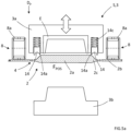
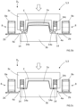
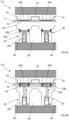
- Figures 1b , 2b , 5a-e , and 9a-b schematically show a forming mould system S for forming cellulose products 1 from an air-formed cellulose blank structure 2.
- the forming mould system S comprises one or more forming moulds 3, where each forming mould 3 comprises a first mould part 3a and a second mould part 3b configured for cooperating with each other during the forming of the cellulose products 1.
- a control unit connected to the forming mould system S is suitably used for controlling different forming steps.
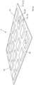
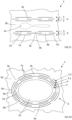
- FIGS 1a , 2a , 3a-b and 4a-b schematically show the air-formed cellulose blank structure 2.
- an air-formed cellulose blank structure 2 according to the disclosure is meant an essentially air-formed fibrous web structure produced from cellulose fibres.
- air-forming of the cellulose blank structure 2 is meant the formation of a cellulose blank structure in a dry-forming process in which cellulose fibres are air-formed to produce the cellulose blank structure 2.
- the cellulose fibres are carried and formed to the fibre blank structure 2 by air as carrying medium. This is different from a normal papermaking process or a traditional wet-forming process, where water is used as carrying medium for the cellulose fibres when forming the paper or fibre structure.
- the cellulose blank structure 2 may, if suitable have a dryness that is mainly corresponding to the ambient humidity in the atmosphere surrounding the air-formed cellulose blank structure 2.
- the dryness of the cellulose blank structure 2 can be controlled in order to have a suitable dryness level when forming the cellulose products 1.
- the air-formed cellulose blank structure 2 may be formed of cellulose fibres in a conventional air-forming process and be configured in different ways.
- the cellulose blank structure 2 may have a composition where the fibres are of the same origin or alternatively contain a mix of two or more types of cellulose fibres, depending on the desired properties of the cellulose products 1.
- the cellulose fibres used in the cellulose blank structure 2 are during the forming process of the cellulose products 1 strongly bonded to each other with hydrogen bonds.
- the cellulose fibres may be mixed with other substances or compounds to a certain amount as will be further described below.
- cellulose fibres is meant any type of cellulose fibres, such as natural cellulose fibres or manufactured cellulose fibres.
- the cellulose blank structure 2 may specifically comprise at least 95% cellulose fibres, or more specifically at least 99% cellulose fibres.
- the air-formed cellulose blank structure 2 may have a single-layer or a multi-layer configuration.
- a cellulose blank structure 2 having a single-layer configuration is referring to a structure that is formed of one layer containing cellulose fibres.
- a cellulose blank structure 2 having a multi-layer configuration is referring to a structure that is formed of two or more layers comprising cellulose fibres, where the layers may have the same or different compositions or configurations.
- the cellulose blank structure 2 may comprise a reinforcement layer comprising cellulose fibres, where the reinforcement layer may be arranged as a carrying layer for other layers of the cellulose blank structure 2.
- the reinforcement layer may have a higher tensile strength than other layers of the cellulose blank structure 2. This is useful when one or more air-formed layers of the cellulose blank structure 2 have compositions with low tensile strength in order to avoid that the cellulose blank structure 2 will break during the forming of the cellulose products 1.
- the reinforcement layer with a higher tensile strength acts in this way as a supporting structure for other layers of the cellulose blank structure 2.
- the reinforcement layer may be of a different composition than the rest of the cellulose blank structure, such as for example a tissue layer containing cellulose fibres, an airlaid structure comprising cellulose fibres, or other suitable layer structures. It is thus not necessary that the reinforcement layer is air-formed.
- the cellulose blank structure 2 may comprise more than one reinforcement layer if suitable.
- the one or more air-formed layers of the cellulose blank structure 2 are fluffy and airy structures, where the cellulose fibres forming the structures are arranged relatively loosely in relation to each other.
- the fluffy cellulose blank structures 2 are used for an efficient forming of the cellulose products 1, allowing the cellulose fibres to form the cellulose products 1 in an efficient way during the forming process.
- the cellulose blank structure 2 comprises one or more defined product sections 2a and a defined residual section 2b.
- the one or more product sections 2a are defined as areas or portions of the cellulose blank structure 2 that are corresponding to the positions of the one or more forming moulds 3 when forming the cellulose products 1.
- the residual section 2b is surrounding or arranged in connection to the one or more product sections 2a.
- At least a portion of the residual section 2b is compressed to a first degree of compression D C1 , higher than a degree of compression Dc of the one or more product sections 2a, as understood from the figures.
- the one or more product sections 2a may be non-compressed or alternatively at least a portion of one or more product sections 2a is compressed to a second degree of compression D C2 .
- the cellulose blank structure 2 may comprise one or more defined residual sections 2b, where each residual section 2b is surrounding or arranged in connection to one or more product sections 2a. Before the forming operations in the forming mould system, at least a portion of each residual section 2b is compressed to a first degree of compression D C1 higher than a degree of compression Dc of the one or more product sections 2a.
- the residual section 2b is suitably compressed to the first degree of compression D C1 .
- the residual section 2b may be compressed to the first degree of compression D C1 , with a density in the range of 40-1300 kg/m 3 .
- the density of the residual section 2b may be measured by cutting out a sample piece of material directly after the cellulose blank structure 2 has been compressed, for example between compacting rollers.
- the thickness of the sample piece from the residual section 2b is measured with a caliper within one minute from the compression, and thereafter the sample piece is weighed.
- the sample piece suitably has a square or circular shape with an area in the range of 400-2000 mm 2 .
- a first sample piece P1 of the residual section 2b is indicated with dotted lines for illustrative purposes, and in the shown embodiment, the first sample piece P1 has a square shape.
- a first area A1 and a first thickness direction T1 of the first sample piece P1 is indicated in figure 1a .
- the residual section 2b may have an embossed pattern, such as for example a waffled surface structure, on one or both sides to enhance the stiffness and strength of the cellulose blank structure 2.
- the cellulose blank structure 2 further comprises one or more transition sections 2c arranged between the one or more product sections 2a and the residual section 2b.
- the degree of compression may vary between the first degree of compression D C1 , and the degree of compression Dc of the one or more product sections 2a.
- the transition sections 2c may have other degrees of compression if suitable.
- the one or more product sections 2a are compressed to a second degree of compression D C2 prior to the feeding of the cellulose blank structure 2 to the forming position F POS .
- the first degree of compression D C1 is higher than the second degree of compression D C2 .
- the one or more product sections 2a may suitably be compressed to the second degree of compression D C2 with a density in the range of 15-400 kg/m 3 .
- the density of the one or more product sections 2a may be measured by cutting out a sample piece of material directly after the cellulose blank structure 2 has been compressed, for example between compacting rollers. The thickness of the sample piece from the one or more product sections 2a is measured with a caliper within one minute from the compression, and thereafter the sample piece is weighed.
- the sample piece suitably has a square or circular shape with an area in the range of 400-2000 mm 2 .
- a pressure of 0.5 kPa is applied onto the whole surface of the sample piece.
- a second sample piece P2 of the one or more product sections 2b is indicated with dotted lines for illustrative purposes, and in the shown embodiment, the second sample piece P2 has a square shape.
- a second area A2 and a second thickness direction T2 of the second sample piece P2 is indicated in figure 1a .
- the forming mould system S may further comprise a compacting unit 11 configured for compacting or compressing the residual section 2b to the first degree of compression D C1 , higher than the degree of compression Dc of the one or more product sections 2a.
- the compacting unit 11 comprises a first compacting roller 11a that is cooperating with a second compacting roller 11b.
- the compacting rollers are arranged on opposite sides of the cellulose blank structure 2, and when the cellulose blank structure 2 is fed between the first compacting roller 11a and the second compacting roller 11b a compression of the cellulose blank structure 2 is accomplished.
- the first compacting roller 11a comprises a plurality of recesses 12 that are forming the product sections 2a, and the area of the first compacting roller 11a between the recesses 12 is forming the residual section 2b of the cellulose blank structure 2 with a higher degree of compression.
- Each of the recesses 12 has a shape and configuration corresponding to the product sections 2a.
- the recesses 12 may be used for compressing the product sections 2a to the second degree of compression D C2 , where the second degree of compression D C2 is lower than the first degree of compression D C1 .
- the second compacting roller 2b may be arranged with recesses that are corresponding to the recesses 12 of the first compacting roller 11a for forming the product sections 2a.
- the forming mould system S may further comprise a cutting unit 9, configured for establishing one or more cutting patterns 4 in the cellulose blank structure 2.
- the cellulose blank structure 2 may be arranged with a cutting pattern 4 in the residual section 2b and/or the transition section 2c at least partly around each product section 2a, as illustrated in f igures 2a-b , 3a-b , 4a-b , 5a-e , 6a-c , and 7a-e .
- Each cutting pattern 4 is in the illustrated embodiments partly separating a part of the cellulose blank structure 2 in connection to a product section 2a from the rest of the cellulose blank structure 2.
- Each cutting pattern 4 is forming at least one bridging structure 4a in the residual section 2b and/or the transition section 2c.
- the bridging structures 4a are connecting the parts of the cellulose blank structure 2 in connection to the product sections 2a and the rest of the cellulose blank structure 2, allowing displacements of the parts of the cellulose blank structure 2 in connection to the product sections 2a, as shown in for example figures 5b-c and 6b .
- the displacements are facilitating the forming of the cellulose products 1 in the one or more forming moulds 3, especially if the cellulose products 1 are having deep drawn configurations.
- the cutting patterns 4 may have any suitable configuration for forming the bridging structures 4a.
- the cutting unit 9 may be arranged as a separate unit upstream the one or more forming moulds 3, as shown in figure 2b , or as one or more arrangements in connection to the one or more forming moulds 3, as shown in figures 9a-b .
- the cutting units described below may be used in connection with different embodiments of the forming mould system S.
- the cutting unit 9 is configured as a rotary die cutter 10.
- the shown rotary die cutter 10 comprises a die cutter 10a and an anvil roll 10b.
- the die cutter 10a comprises a plurality of cutting elements 10c that are forming the cutting patterns 4 in the cellulose blank structure 2 when the cellulose blank structure 2 is fed between the die cutter 10a and the anvil roll 10b.
- the cutting elements 10c thus have a configuration that is corresponding to the shape of the cutting patterns 4.
- the rotary die cutter 10 may also have the function as a compacting roller in a similar way as described above in connection to figure 1b .
- the die cutter 10a comprises a plurality of recesses 12 that are forming the product sections 2a, and the area of the die cutter 10a between the recesses 12 is forming the residual section 2b of the cellulose blank structure 2 with a higher degree of compression.
- Each of the recesses 12 has a shape and configuration corresponding to the product sections 2a.
- the recesses 12 may be used for compressing the product sections 2a to the second degree of compression D C2 , where the second degree of compression D C2 is lower than the first degree of compression D C1 .
- the anvil roll 2b may be arranged with recesses that are corresponding to the recesses 12 of the die cutter 10a for forming the product sections 2a.
- the cutting unit 9 may have other suitable configurations.
- the cutting unit 9 is configured as a press cutting device 20 arranged in connection to the forming moulds 3 of the forming mould system S.
- the press cutting device 20 comprises a movably arranged common plate structure 20a with a plurality of cutting elements 20b with cutting edges that are forming the cutting patterns 4 in the cellulose blank structure 2 when the cellulose blank structure 2 is arranged between the first mould parts 3a and the second mould parts 3b.
- the cutting patterns 4 are formed in the residual section 2b and/or the transition section 2c at least partly around each product section 2a, and the cutting elements 20b thus have a configuration that is corresponding to the shape of the cutting patterns 4.
- the plate structure 20a with the cutting elements 20b is in a non-cutting position shown in figure 9a arranged in connection to the second mould parts 3b.
- a pre-formed cellulose blank structure 2 with product sections 2a and residual sections 2b is arranged in connection to the first mould parts 3a.
- the press cutting device 20 further comprises pressure cylinders 20c that are arranged for displacing the plate structure 20a with the cutting elements 20b from the non-cutting position to a cutting position shown in figure 9b .
- the cutting elements 20b meet an anvil structure 20d arranged in connection to the first mould parts 3a for establishing the cutting patterns 4 in the cellulose structure.
- the anvil structure 20d may be made of a suitable material, such as for example a flexible plate structure made of polyurethane.
- each cutting pattern 4 comprises a first cut 5 arranged around and in connection to a corresponding product section 2a, where the first cut 5 comprises a first cut line 5a with a first intermediate section 5b forming the at least one bridging structure 4a.
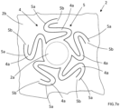
- FIG 7a an exemplified cutting pattern 4 with a spiral shape is schematically illustrated, where the first cut 5 is arranged around and in connection to the product section 2a.
- the first cut 5 comprises the first cut line 5a with the first intermediate section 5b between overlapping sections of the first cut line 5a, as shown in the figure.
- the intermediate section 5b is forming the at least one bridging structure 4a.
- each cutting pattern 4 comprises a non-continuous first cut 5 arranged around and in connection to a corresponding product section 2a, and a non-continuous second cut 6 arranged around and outwards of the non-continuous first cut 5 relative to the product section 2a.
- the non-continuous first cut 5 comprises one or more first cut lines 5a with one or more first intermediate sections 5b between the one or more first cut lines 5a.
- the non-continuous second cut 6 comprises one or more second cut lines 6a with one or more second intermediate sections 6b between the one or more second cut lines 6a.
- the one or more first intermediate sections 5b and the one or more second intermediate sections 6b are forming the at least one bridging structure 4a.
- exemplified cutting patterns 4 are illustrated where the cutting patterns 4 comprise the non-continuous first cut 5 arranged around and in connection to a corresponding product section 2a, and the non-continuous second cut 6 arranged around and outwards of the non-continuous first cut 5 relative to the product section 2a.
- the non-continuous first cut 5 comprises a plurality of first cut lines 5a with first intermediate sections 5b between the first cut lines 5a.
- the non-continuous second cut 6 comprises a plurality of second cut lines 6a with second intermediate sections 6b between the second cut lines 6a.
- the first intermediate sections 5b and the second intermediate sections 6b are forming the bridging structures 4a.
- the non-continuous first cut 5 and the non-continuous second cut 6 may as illustrated be arranged in an overlapping relationship relative to each other, where the one or more first cut lines 5a are overlapping the one or more second intermediate sections 6b and the one or more second cut lines 6a are overlapping the one or more first intermediate sections 5b.
- each cutting pattern 4 may further comprise at least one non-continuous additional cut 7 arranged around and outwards of the non-continuous second cut 6 relative to the product section 2a, where each of the at least one non-continuous additional cut 7 comprises one or more additional cut lines 7a with one or more additional intermediate sections 7b between the one or more additional cut lines 7a.
- FIG 7c an exemplified cutting pattern 4 is illustrated where the cutting pattern 4 comprise the non-continuous first cut 5 arranged around and in connection to a corresponding product section 2a, the non-continuous second cut 6 arranged around and outwards of the non-continuous first cut 5 relative to the product section 2a, and one non-continuous additional cut 7 arranged around and outwards of the non-continuous second cut 6 relative to the product section 2a.
- the non-continuous additional cut 7 comprises a plurality of additional cut lines 7a with additional intermediate sections 7b between the additional cut lines 7a.
- FIG 7d an exemplified cutting pattern 4 is illustrated where the cutting pattern 4 comprise the non-continuous first cut 5 arranged around and in connection to a corresponding product section 2a, the non-continuous second cut 6 arranged around and outwards of the non-continuous first cut 5 relative to the product section 2a, and two non-continuous additional cuts 7 arranged around and outwards of the non-continuous second cut 6 relative to the product section 2a.
- a non-continuous first additional cut 7:1 is arranged around and outwards of the non-continuous second cut 6 relative to the product section 2a
- a non-continuous second additional cut 7:2 is arranged around and outwards of the non-continuous first additional cut 7:1 relative to the product section 2a.
- Each of the non-continuous additional cuts 7 comprises a plurality of additional cut lines 7a with additional intermediate sections 7b between the additional cut lines 7a.
- each cutting pattern 4 may instead comprise only a non-continuous first cut 5 arranged around and in connection to a corresponding product section 2a.
- the non-continuous first cut 5 comprises one or more first cut lines 5a with one or more first intermediate sections 5b between the one or more first cut lines 5a, and the one or more first intermediate sections 5b are forming the at least one bridging structure 4a.
- FIG 7e an exemplified cutting pattern 4 comprising only a non-continuous first cut 5 arranged around and in connection to a corresponding product section 2a is illustrated.
- the non-continuous first cut 5 comprises a plurality of first cut lines 5a with first intermediate sections 5b between the first cut lines 5a.
- the first intermediate sections 5b are forming the bridging structures 4a.
- Each cut 5, 6, 7 is suitably extending through the cellulose blank structure 2.
- at least one of the intermediate sections 5b, 6b, 7b comprise a cut extending partly through the cellulose blank structure 2.
- some of the intermediate sections 5b, 6b, 7b may be made narrow and configured to break during forming of the cellulose products 1.
- the narrow configuration of the intermediate sections 5b, 6b, 7b are allowing transportation of the cellulose blank structure 2 without breakage or separation, for a secure positioning of the cellulose blank structure 2 in relation to the one or more forming moulds 3.
- the forming mould system S comprises one or more forming moulds 3, where each forming mould 3 comprises the first mould part 3a and the second mould part 3b, which are cooperating with each other during the forming of the cellulose products 1.
- the first mould part 3a and the second mould part 3b are movably arranged in relation to each other, and the first mould part 3a and the second mould part 3b are configured for moving in relation to each other in a pressing direction D P .
- the second mould part 3b is stationary and the first mould part 3a is movably arranged in relation to the second mould part 3b in the pressing direction D P .
- the first mould part 3a is configured to move both towards the second mould part 3b and away from the second mould part 3b in linear movements along an axis extending in the pressing direction D P .
- first mould part 3a may be stationary with the second mould part 3b movably arranged in relation to the first mould part 3a, or both mould parts may be movably arranged in relation to each other.
- the forming mould system S may be of a single-cavity configuration or alternatively of a multi-cavity configuration.
- a single-cavity forming mould system comprises only one forming mould 3 with first and second mould parts.
- a multi-cavity forming mould system comprises two or more forming moulds 3, each having first and second mould parts.
- the forming mould system S is arranged as a multi-cavity forming mould system comprising a plurality of forming moulds 3 with first and second mould parts, where the movements of the mould parts suitably are synchronized for a simultaneous forming operation.
- the part of the forming mould system S shown in figures 5a-e and 6a-c could illustrate the single-cavity configuration, or alternatively a section of the multi-cavity configuration.
- the forming mould system S will be described in connection to a multi-cavity forming mould system, but the disclosure is equally applicable on a single-cavity forming mould system.
- the expression moving in the pressing direction D P includes a movement along an axis extending in the pressing direction D P , and the movement may take place along the axis in opposite directions.
- the expression further includes both linear and non-linear movements of a mould part for all embodiments, where the result of the movement during forming is a repositioning of the mould part in the pressing direction D P .
- the air-formed cellulose blank structure 2 is first provided from a suitable source.
- the cellulose blank structure 2 may be air-formed from cellulose fibres and arranged on rolls or in stacks. The rolls or stacks may thereafter be arranged in connection to the forming mould system S.
- the cellulose blank structure 2 may be air-formed from cellulose fibres in connection to the forming mould system S and directly fed to the mould parts.
- the forming mould system S further comprises a feeding unit 8 configured for feeding the cellulose blank structure 2 in a feeding direction D F to a forming position F POS in the forming mould system S.
- the feeding unit 8 comprises one or more feeder belts 8a that are used for transporting the cellulose blank structure 2 in the feeding direction D F to the forming position F POS between the first mould part 3a and the second mould part 3b.
- the feeder belts 8a are further used for holding the cellulose blank structure in position during the forming process.
- the feeder belts 8a may have any suitable configuration for transporting the cellulose blank structure 2.
- the feeder belts 8a are schematically illustrated in perspective views.
- the feeder belts 8a may be of vacuum-type with suction channels 8b for holding the cellulose blank structure 2 during transportation, as indicated in figures 6a-c .
- feeder belts 8a are arranged on each side of the first mould parts 3a.
- the feeder belts 8a are cooperating to transport the cellulose blank structure 2 to the forming position F POS shown in figure 5a .
- the cellulose blank structure 2 is arranged between the first mould parts 3a and the second mould parts 3b.
- the feeding unit 8 may have other suitable configurations, such as feeding rollers.
- the feeding unit 8 is feeding the cellulose blank structure 2 in the feeding direction D F to the forming position F POS in the forming mould system S.
- each product section 2a is arranged between a corresponding first mould part 3a and second mould part 3b.
- the product sections 2a are thus arranged in the cellulose blank structure 2 in a pattern corresponding to the arrangement of the one or more forming moulds 3 in the forming mould system S, as illustrated in figures 1b and 2b .
- the first mould parts 3a are arranged for forming the cellulose products 1 through interaction with the corresponding second mould parts 3b.
- the cellulose blank structure 2 is in each forming mould 3 exerted to a product forming pressure P F of at least 1 MPa, preferably in the range of 4-20 MPa, and a product forming temperature T F in the range of 100°C to 300°C.
- the cellulose products 1 are thus formed from the cellulose blank structure 2 between each of the first mould parts 3a and corresponding second mould parts 3b by heating the cellulose blank structure 2 to the forming temperature T F in the range of 100-300 °C, and by pressing the cellulose blank structure 2 with the forming pressure P F in the range of 1-100 MPa, preferably 4-20 MPa.
- T F the forming temperature
- P F the forming pressure
- strong hydrogen bonds are formed between the cellulose fibres in the cellulose blank structure 2 arranged between the first mould parts 3a and the second mould parts 3b.
- the temperature and pressure levels are for example measured in the cellulose blank structure 2 during the forming process with suitable sensors arranged in or in connection to the cellulose fibres in the cellulose blank structure 2.
- the first mould parts 3a are moved towards the second mould parts 3b in the pressing direction D P , as illustrated with the arrow in figure 5b .
- the position of the cellulose blank structure 2 in figure 5b is schematically shown in a perspective view without the first mould part 3a for illustrative purposes.
- the residual section 2b and the one or more product sections 2a may at least partly be displaced relative to each other in a pressing direction D P of the forming mould system S prior to the forming of the cellulose products 1, as schematically illustrated in figure 6b .
- the cellulose blank structure 2 is being compacted between the mould parts.
- the first mould parts 3a have been further moved towards the second mould parts 3b and reached a product forming position, in which the forming pressure P F and forming temperature T F is exerted onto the cellulose blank structure 2.
- a forming cavity C for forming the cellulose products 1 is formed between each first mould part 3a and second mould part 3b during forming of the cellulose products 1 when each first mould part 3a is pressed towards the corresponding second mould part 3b with the cellulose blank structure 2 arranged between the mould parts.
- the forming pressure P F and the forming temperature T F are applied to the cellulose blank structure 2 in each forming cavity C.
- the forming of the cellulose products 1 may further include a cutting operation, where the cellulose products 1 are cut out from the cellulose blank structure 2 in the forming mould system S during forming of the cellulose products 1.
- the mould parts may for example be arranged with cutting devices for such an operation.
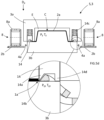
- FIG 5c-d positions of an exemplified forming mould system S is illustrated, in which an edge-forming operation is taking place for forming edge structures 1a of the cellulose products 1.
- the edge-forming operation may be used instead of a cutting operation for separating the cellulose products 1 from the cellulose blank structure 2 and at the same time forming the edge structures 1a.
- Each of the first mould parts 3a comprises an edge-forming device 14 with a protruding element 14a configured for compacting and separating fibres of the cellulose blank structure 2.
- the protruding element 14a is arranged with an edge section 14b that is facing the second mould part 3b.
- the protruding element 14a is suitably arranged as a continuous element extending around the edge-forming device 14, where the protruding element 14a has an extension corresponding to the edge shape or outer contour of the cellulose products 1 produced in the forming mould system S. It should however be understood that the protruding element 14a may have any suitable extension, such as for example non-continuous, depending on the shape of the cellulose products 1 to be formed.
- the protruding element 14a may further have a pointed cross-sectional configuration with the edge section 14b, as shown in figure 5d .
- the protruding element 14a with the edge section 14b may have other suitable cross-sectional configurations in other non-illustrated embodiments, such as a rounded or flat edge section.
- the edge-forming device 14 may be movably arranged in relation to a base structure of the first mould part 3a, as illustrated in figures 5a-e , and the edge-forming device 14 is adapted for interacting with a pressure member arranged in the base structure.
- the edge-forming device 14 may have any suitable shape and configuration, depending on the shape and configuration of the cellulose products 1.
- the edge-forming device 14 may for example be slidingly arranged in relation to the base structure in the pressing direction D P .
- the pressure member may comprise one or more springs 14c arranged between the base structure and the edge-forming device 14.
- the pressure member may alternatively be arranged as a hydraulic or pneumatic pressure device.
- the edge-forming device 14 may also be configured as a non-movable structure with the protruding element 14a arranged on the first mould part 3a.
- the edge-forming device may instead be arranged on the second mould parts 3b, or on both the first mould parts 3a and the second mould parts 3b.
- each edge-forming device 14 During the movement of the first mould parts 3a towards the second mould parts 3b, the protruding element 14a of each edge-forming device 14 is separating some of the fibres 2a of the cellulose blank structure 2 by forces applied to the cellulose blank structure 2 by the protruding element 14a.
- a stopping member 14d arranged on each edge-forming device 14 is preventing direct contact between the protruding element 14a and the second mould part 3b during forming of the compacted edge structure 1a, as indicated in figure 5d .
- the stopping member 14d is arranged as a protrusion on the edge-forming device 14, with an extension in the pressing direction D P that is greater than the extension of the protruding element 14a.
- each stopping member 14d is meeting the corresponding second mould part 3b, as shown in figures 5c-d , and through the greater extension in the pressing direction D P , direct contact between the protruding element 14a and the second mould part 3b is prevented.
- the cutting pattern 4 in the cellulose blank structure 2 is establishing openings in the cellulose blank structure 2, allowing direct contact between each stopping member 14d and corresponding second mould part 3b, as understood from figure 5d .
- the stopping member 14d may be arranged as a continuous element extending around each edge-forming device 14, or alternatively as one or more protrusions extending from each edge-forming device 14.
- the stopping members 14d may instead be arranged on the second mould parts 3b, or both on the first mould parts 3a and the second mould parts 3b.
- Each stopping member 14d is preventing contact between the protruding element 14a and corresponding second mould part 3b during forming of the compacted edge structure 1a, and with this arrangement, the protruding element 14a is arranged at a small distance from the second mould part 4. A small gap is formed between the protruding element 14a and the second mould part 3b.
- edge structures 1a When forming the edge structures 1a, fibres of the cellulose blank structure 2 are gathered in the area between each protruding element 14a and corresponding second mould part 3b. At the same time, an edge-forming pressure P EF and an edge-forming temperature T EF is applied onto the cellulose blank structure 2. When the edge-forming pressure P EF and the edge-forming temperature T EF are applied to the cellulose blank structure 2, a highly compacted edge structure 1a is formed.
- the edge structure 1a is suitably formed as a thin edge extending around the periphery of the cellulose products 1, and the highly compacted formed edge structure 1a is efficiently preventing delamination of and moisture absorption into the cellulose products 1.
- a very thin compacted cellulose structure is formed that could be used for an easy separation of the cellulose product 1 and the cellulose blank structure 2 outside the forming mould parts.
- the thin highly compacted cellulose structure is during the edge-forming operation exposed to high compressive stresses, and during the edge-forming process the cellulose fibres fracture due to the stored energy, high tension, and/or tensile stress, in the cellulose structure when the high pressure level is applied onto the cellulose fibres with the edge-forming pressure P EF .
- the residual fibres in the cellulose blank structure 2 remaining after the forming of the cellulose products 1 may be reused.
- the edge-forming operation is with the edge-forming device 14 taking place with the product-forming operation.
- a suitable edge-forming pressure P EF applied onto the cellulose blank structure 2 is at least 10 MPa, preferably in the range of 10-4000 MPa, or more preferably in the range of 100-4000 MPa, when forming the edge-structure 1a.
- a suitable edge-forming temperature T EF applied onto the cellulose blank structure 2 is in the range of 50-300 °C, preferably in the range of 100-300 °C, when forming the edge-structure 1a.
- a deformation element E for establishing the product forming pressure may be arranged in connection to each first mould part 3a and/or second mould part 3b. In the embodiment illustrated in figures 5a-e , the deformation element E is attached to the first mould part 3a. By using a deformation element E, the forming pressure P F may be an isostatic forming pressure.
- the first mould parts 3a and/or the second mould parts 3b may comprise the deformation elements E, and the deformation elements E are configured for exerting the forming pressure P F on the cellulose blank structure 2 in the forming cavities C during forming of the cellulose products 1.
- the deformation elements E may be attached to the first mould parts 3a and/or the second mould parts 3b with suitable attachment means, such as for example glue or mechanical fastening members.
- the deformation elements E are deformed to exert the forming pressure P F on the cellulose blank structure 2 in the forming cavities C and through deformation of the deformation elements E, an even pressure distribution is achieved even if the cellulose products 1 are having complex three-dimensional shapes or if the cellulose blank structure 2 is having a varied thickness.
- the deformation elements E are made of a material that can be deformed when a force or pressure is applied, and the deformation elements E are suitably made of an elastic material capable of recovering size and shape after deformation.
- the deformation elements E may further be made of a material with suitable properties that is withstanding the high forming pressure P F and forming temperature T F levels used when forming the cellulose products 1.
- Certain elastic or deformable materials have fluid-like properties when being exposed to high pressure levels. If the deformation elements E are made of such a material, an even pressure distribution can be achieved in the forming process, where the pressure exerted on the cellulose blank structure 2 in the forming cavity C from the deformation elements E is equal or essentially equal in all directions between the mould parts. When each deformation element E under pressure is in its fluid-like state, a uniform fluid-like pressure distribution is achieved.
- the forming pressure P F is with such a material thus applied to the cellulose blank structure 2 from all directions, and the deformation element E is in this way during the forming of the cellulose products 1 exerting an isostatic forming pressure on the cellulose blank structure 2.
- Each deformation element E may be made of a suitable structure of elastomeric material or materials, and as an example, the deformation element E may be made of a massive structure or an essentially massive structure of silicone rubber, polyurethane, polychloroprene, or rubber with a hardness in the range 20-90 Shore A.
- Other materials for the deformation elements E may for example be suitable gel materials, liquid crystal elastomers, and MR fluids.
- the forming mould system S further comprises a heating unit.
- the heating unit is configured for applying the forming temperature T F onto the cellulose blank structure 2 in each forming cavity C.
- the heating unit is further suitably configured for applying the edge-forming temperature T EF onto the cellulose blank structure 2 during the edge-forming operation.
- the heating unit may have any suitable configuration.
- a suitable heating unit such as a heated forming mould part or heated forming mould parts may be used for establishing the forming temperature T F and the edge-forming temperature T EF .
- the heating unit may be integrated in or cast into the first mould parts 3a and/or the second mould parts 3b, and suitable heating devices are e.g. electrical heaters, such as a resistor element, or fluid heaters. Other suitable heat sources may also be used.
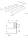
- FIG 8a an alternative embodiment of the cellulose blank structure 2 is schematically illustrated.
- the cellulose blank structure 2 comprises one or more defined product sections 2a and residual sections 2b, where the residual sections 2b are arranged in connection to the one or more product sections 2a.
- the residual section 2b is compressed to a first degree of compression D C1 , higher than a degree of compression D C of the one or more product sections 2a, as understood from the figure.
- the cellulose blank structure 2 further comprises one or more transition sections 2c arranged between the one or more product sections 2a and the residual section 2b.
- the degree of compression is varying between the first degree of compression D C1 , and the degree of compression D C of the one or more product sections 2a.
- the one or more product sections 2a may be compressed to a second degree of compression D C2 , where the first degree of compression D C1 is higher than the second degree of compression D C2 .
- the respective sections may have densities as described above.
- the configurations of the cellulose blank structure 2 in figures 1a , 2a , and 8a may be fed to the forming position F POS with the feeding unit 8 described above.
- the feeding unit 8 instead has a tractor feed configuration for transporting the cellulose blank structure 2 to the feeding position F POS .
- the feeding unit 8 comprises a first roller 15a and a second cooperating roller 15b, and the cellulose blank structure 2 is arranged between the rollers, as shown in figure 8b .
- the first roller 15a and the second roller 15b are compacting the cellulose blank structure 2 for forming the product sections and the residual section 2b.
- the first roller 15a comprises recessed portions 16a for forming the product sections 2a, in a similar way as described in connection to figures 1b and 2b .
- Non-recessed portions 16b of the first roller 15a are arranged on each side of the recessed portions 16a for forming the residual sections 2b.
- the first roller 15a comprises a plurality of perforation cutters 17 in the non-recessed portions 16b for forming tractor feed holes 18 arranged in rows R of the cellulose blank structure 2.
- the tractor feed holes 18 are used for the transportation of the cellulose blank structure 2.
- the first roller 15a is arranged with five rows of perforation cutters 17 arranged on each side of the respective recessed portions 16a.
- the perforation cutters 17 are in this way forming five rows R of tractor feed holes 18 in the cellulose blank structure 2.
- the feeding unit 8 further comprises sprocket wheels 19 that are used for feeding the cellulose blank structure 2 to the feeding position F POS , where sprockets are engaging the tractor feed holes 18.
- the first roller 15a and the second roller 15b are illustrated more in detail with the plurality of peroration cutters 17.
- the perforation cutters 17 are arranged as sharp protrusions that are cutting out the tractor feed holes 18 in the cellulose blank structure 2.
- the tractor feed holes 18 may be partly cut by the perforation cutters as illustrated in the enlarged portions of the cellulose blank structure 2 in figure 8b for avoiding loose separated cut-out pieces 18a of residual material.
- the tractor feed holes 18 are engaging the sprocket wheels 19 during the feeding operation.
- the partly cut tractor feed holes 18 may be arranged with connecting portions 18b having hinge-like configurations for holding the cut-out pieces 18a of fibre material connected to the cellulose blank structure 2, as shown in figure 8b .
- the rotational placement of the connecting portions 18b in relation to the partly cut tractor feed holes 18 may be alternated in the cutting pattern to improve registration between the tractor feed holes 18 and the sprocket wheels 19, as illustrated in the enlarged portions of the cellulose blank structure 2 in figure 8b .
- the connection portions 18b of two adjacent tractor feed holes 18 are arranged on opposite sides relative to their respective tractor feed holes 18.
- a non-transitory computer-readable storage medium storing one or more programs configured to be executed by one or more processors of the control unit of the forming mould system S, the one or more programs comprising instructions for performing the method according to any one of the above-discussed embodiments.
- a cloud computing system can be configured to perform any of the method aspects presented herein.
- the cloud computing system may comprise distributed cloud computing resources that jointly perform the method aspects presented herein under control of one or more computer program products.
- the processor may be connected to one or more communication interfaces and/or sensor interfaces for receiving and/transmitting data with external entities such as e.g. sensors, an off-site server, or a cloud-based server.
- the processor or processors of the forming mould system S may be or include any number of hardware components for conducting data or signal processing or for executing computer code stored in memory.
- the system may have an associated memory, and the memory may be one or more devices for storing data and/or computer code for completing or facilitating the various methods described in the present description.
- the memory may include volatile memory or non-volatile memory.
- the memory may include database components, object code components, script components, or any other type of information structure for supporting the various activities of the present description. According to an exemplary embodiment, any distributed or local memory device may be utilized with the systems and methods of this description.
- the memory is communicably connected to the processor (e.g., via a circuit or any other wired, wireless, or network connection) and includes computer code for executing one or more processes described herein.
Landscapes
- Engineering & Computer Science (AREA)
- Mechanical Engineering (AREA)
- Manufacturing & Machinery (AREA)
- Casting Or Compression Moulding Of Plastics Or The Like (AREA)
- Moulds For Moulding Plastics Or The Like (AREA)
- Paper (AREA)
- Blow-Moulding Or Thermoforming Of Plastics Or The Like (AREA)
- Making Paper Articles (AREA)
- Dry Formation Of Fiberboard And The Like (AREA)
- Processing And Handling Of Plastics And Other Materials For Molding In General (AREA)
Description
- The present disclosure relates to a method for forming cellulose products in a forming mould system from an air-formed cellulose blank structure. The forming mould system comprises one or more forming moulds, wherein each forming mould comprises a first mould part and a second mould part configured for cooperating with each other during the forming of the cellulose products. The disclosure further relates to a forming mould system and a cellulose blank structure.
- Cellulose fibres are often used as raw material for producing or manufacturing products. Products formed of cellulose fibres can be used in many different situations where there is a need for having sustainable products. A wide range of products can be produced from cellulose fibres and a few examples are disposable plates and cups, cutlery, lids, bottle caps, coffee pods, and packaging materials.
- Forming moulds are commonly used when manufacturing cellulose products from raw materials including cellulose fibres, and traditionally the cellulose products have been produced with wet-forming techniques. A material commonly used for wet-forming cellulose fibre products is wet moulded pulp. Wet moulded pulp has the advantage of being considered as a sustainable packaging material, since it is produced from biomaterials and can be recycled after use. Consequently, wet moulded pulp has been quickly increasing in popularity for different applications. Wet moulded pulp articles are generally formed by immersing a suction forming mould into a liquid or semi liquid pulp suspension or slurry comprising cellulose fibres, and when suction is applied, a body of pulp is formed with the shape of the desired product by fibre deposition onto the forming mould. With all wet-forming techniques, there is a need for drying of the wet moulded product, where the drying is a very time and energy consuming part of the production. The demands on aesthetical, chemical and mechanical properties of cellulose products are increasing, and due to the properties of wet-formed cellulose products, the mechanical strength, flexibility, freedom in material thickness, and chemical properties are limited. It is also difficult in wet-forming processes to control the mechanical properties of the products with high precision.
- One development in the field of producing cellulose products is the forming of cellulose fibres without using wet-forming techniques. Instead of forming the cellulose products from a liquid or semi liquid pulp suspension or slurry, an air-formed cellulose blank structure is used. The air-formed cellulose blank structure is inserted into a forming mould and during the forming of the cellulose products the cellulose blank is subjected to a high forming pressure and a high forming temperature. A respective method is disclosed in document
WO 2019/209160 A1 . When inserting the cellulose blank structure into the forming mould, there is a risk that the cellulose blank structure breaks apart in an undesired manner, which leads to an improper forming of the cellulose products. This is a common issue with traditional cellulose high pressure forming methods, especially for deep-drawn products, leading to products with low quality. Other problems with traditional forming methods using standard cellulose blank structures, especially when forming deep-drawn products, are that that cracks, fibre separations, material fractures, or other unwanted structural weakenings of the cellulose blank structure are occurring during the insertion of the cellulose blank structure into the forming mould and during the forming process in the forming mould. - There is thus a need for an improved method, forming mould system, and cellulose blank structure, for forming cellulose products from an air-formed cellulose blank structure.
- An object of the present disclosure is to provide a method for forming cellulose products in a forming mould system from a cellulose blank structure, a forming mould system, and a cellulose blank structure, where the previously mentioned problems are avoided. This object is at least partly achieved by the features of the independent claims. The dependent claims contain further developments of the method for forming cellulose products in a forming mould system from a cellulose blank structure.
- The disclosure concerns a method for forming cellulose products in a forming mould system from an air-formed cellulose blank structure. The forming mould system comprises one or more forming moulds, wherein each forming mould comprises a first mould part and a second mould part configured for cooperating with each other during the forming of the cellulose products. The method comprises the steps: providing the cellulose blank structure, and in the cellulose blank structure defining one or more product sections and a residual section surrounding or arranged in connection to the one or more product sections; compressing at least a portion of the residual section to a first degree of compression higher than a degree of compression of the one or more product sections; feeding the cellulose blank structure in a feeding direction to a forming position in the forming mould system, where in the forming position each product section is arranged between a corresponding first mould part and second mould part; forming the cellulose products from the cellulose blank structure between the first mould part and the second mould part by heating the cellulose blank structure to a forming temperature in the range of 100-300 °C; and pressing the cellulose blank structure with a forming pressure in the range of 1-100 MPa, preferably 4-20 MPa.
- Advantages with these features are that when transporting and inserting the cellulose blank structure into the forming mould, the risk for the cellulose blank structure to break apart in an undesired manner is prevented. The solution leads to better forming of the cellulose products with improved product quality, especially for deep-drawn products. Cracks, fibre separations, material fractures, or other unwanted structural weakenings of the cellulose blank structure is with the method minimized through the forming of the product sections and residual section, when the cellulose blank structure is inserted into the forming mould and during the forming process in the forming mould. With the residual section compressed to a first degree of compression higher than a degree of compression of the one or more product sections, the transportation of the cellulose blank structure is simplified and the residual sections are through the higher degree of compression allowing transportation of the cellulose blank structure at higher feeding speeds without breaking the structure. The less compressed product sections are allowing a flexible fibre transportation into the forming moulds. Higher feeding speeds are reducing the product forming cycle time.
- According to an aspect of the disclosure, the cellulose blank structure further comprises one or more transition sections arranged between the one or more product sections and the residual section. In the one or more transition sections, the degree of compression is varying between the first degree of compression and the degree of compression of the one or more product sections. The transition sections are forming structures that are supporting the fibre transportation into the forming moulds. The transition sections are further preventing fractures of the fibres in the cellulose blank structure between the product sections and the residual section.
- According to another aspect of the disclosure, the method further comprises the step: compressing at least a portion of the one or more product sections to a second degree of compression prior to the feeding of the cellulose blank structure to the forming position, wherein the first degree of compression is higher than the second degree of compression. The second degree of compression can be different for different types of products formed, and more deep-drawn products often require a lower degree of compression.
- According to an aspect of the disclosure, the method further comprises the step: in the forming position at least partly displacing the residual section and the one or more product sections relative to each other in a pressing direction of the forming mould system prior to the forming of the cellulose products. The displacement is facilitating the forming of the cellulose products, especially for deep-draw products, where the fibres in the cellulose blank structure are allowed to move in relation to each other.
- According to another aspect of the disclosure, the method further comprises the step: arranging a cutting pattern in the residual section and/or the transition section at least partly around each product section. Each cutting pattern is forming at least one bridging structure in the residual section and/or the transition section for keeping each product section partly connected with the residual section and/or the transition section. The cutting pattern are supporting the forming of the cellulose products, where the products sections are allowed to more relative to the rest of the cellulose blank structure. The bridging structures are efficiently keeping the product sections in position in relation to the forming moulds during the product forming operation.
- According to a further aspect of the disclosure, each cutting pattern comprises a non-continuous first cut arranged around and in connection to a corresponding product section. The non-continuous first cut comprises one or more first cut lines with one or more first intermediate sections between the one or more first cut lines. The one or more first intermediate sections are forming the at least one bridging structure. The cutting pattern with this configuration is simple in design.
- According to an aspect of the disclosure, each cutting pattern comprises a first cut arranged around and in connection to a corresponding product section. The first cut comprises a first cut line with a first intermediate section forming the at least one bridging structure.
- According to another aspect of the disclosure, each cutting pattern comprises a non-continuous first cut arranged around and in connection to a corresponding product section, and a non-continuous second cut arranged around and outwards of the non-continuous first cut relative to the product section. The first cut and the second cut are efficiently cooperating to form the at least one bridging structure.
- According to a further aspect of the disclosure, the non-continuous first cut comprises one or more first cut lines with one or more first intermediate sections between the one or more first cut lines. The non-continuous second cut comprises one or more second cut lines with one or more second intermediate sections between the one or more second cut lines. The one or more first intermediate sections and the one or more second intermediate sections are forming the at least one bridging structure. This type of cutting pattern is efficiently allowing displacement of the product sections in relation to the rest of the cellulose blank structure during the product forming operation, and is suitable for deep-drawn products.
- According to an aspect of the disclosure, the non-continuous first cut and the non-continuous second cut are arranged in an overlapping relationship relative to each other. The one or more first cut lines are overlapping the one or more second intermediate sections, and the one or more second cut lines are overlapping the one or more first intermediate sections.
- According to another aspect of the disclosure, each cutting pattern further comprises at least one non-continuous additional cut arranged around and outwards of the non-continuous second cut relative to the product section. Each of the at least one non-continuous additional cut comprises one or more additional cut lines with one or more additional intermediate sections between the one or more additional cut lines. This type of cutting pattern is efficiently allowing displacement of the product sections in relation to the rest of the cellulose blank structure during the product forming operation, and is suitable for deep-drawn products.
- According to a further aspect of the disclosure, each cut is extending through the cellulose blank structure. In this way, each cut is forming an opening in the cellulose blanks structure for an efficient displacement of the product sections.
- According to an aspect of the disclosure, at least one of the intermediate sections comprise a cut extending partly through the cellulose blank structure. The partly extending cut may support the positioning of the product sections relative to the forming moulds during transportation of the cellulose blank structure.
- According to another aspect of the disclosure, the method further comprises the step: arranging the one or more cutting patterns in the residual section and/or the transition section around each product section with a cutting unit. The cutting unit is used for forming the cutting patterns and may have different configurations, such as a rotary die cutter or a press cutting device.
- According to a further aspect of the disclosure, the cutting unit is arranged as a rotary die cutter. The method further comprises the step: forming the one or more cutting patterns and compressing at least a part of the residual section with the rotary die cutter in a single operational step; or forming the one or more cutting patterns, compressing at least a part of the residual section, and compressing at least a portion of the one or more product sections with the rotary die cutter in a single operational step.
- According to an aspect of the disclosure, the method further comprises the step: cutting out the cellulose products from the cellulose blank structure in the forming mould system during forming of the cellulose products. With this method, the cellulose products can be cut out from the cellulose blank structure in direct connection to the forming moulds when the cellulose blank structure is arranged in the forming position.
- According to another aspect of the disclosure, the product sections are arranged in the cellulose blank structure in a pattern corresponding to the arrangement of the one or more forming moulds in the forming mould system.
- The cellulose blank structure may be transported in the feeding direction with one or more feeder belts. The feeder belts are providing efficient and simple transportation means of the cellulose blank structure.
- The disclosure further concerns a forming mould system for forming cellulose products from an air-formed cellulose blank structure. The cellulose blank structure comprises one or more defined product sections and a defined residual section surrounding or arranged in connection to the one or more product sections. The forming mould system comprises one or more forming moulds, where each forming mould comprises a first mould part and a second mould part configured for cooperating with each other during the forming of the cellulose products. The forming mould system further comprises: a compacting unit configured for compressing at least a portion of the residual section to a first degree of compression higher than a degree of compression of the one or more product sections; and a feeding unit configured for feeding the cellulose blank structure in a feeding direction to a forming position in the forming mould system. In the forming position, each product section is arranged between a corresponding first mould part and second mould part. The one or more forming moulds are configured for: forming the cellulose products from the cellulose blank structure between the first mould part and the second mould part by heating the cellulose blank structure to a forming temperature in the range of 100-300 °C; and pressing the cellulose blank structure with a forming pressure in the range of 1-100 MPa, preferably 4-20 MPa. Advantages with these system features are that when inserting the cellulose blank structure into the forming mould, the risk for the cellulose blank structure to break apart in an undesired manner is prevented. The solution leads to better forming of the cellulose products, especially for deep-drawn products.
- The disclosure further concerns a cellulose blank structure for forming cellulose products in a forming mould system. The cellulose blank structure is air-formed and comprises one or more defined product sections and a defined residual section surrounding or arranged in connection to the one or more product sections. At least a portion of the residual section has a first degree of compression higher than a degree of compression of the one or more product sections. The cellulose blank structure further comprises: one or more transition sections arranged between the one or more product sections and the residual section. In the transition section the degree of compression is varying between the first degree of compression and the degree of compression of the one or more product sections. The cellulose blank structure further comprises a cutting pattern in the residual section and/or the transition section at least partly around each product section. Each cutting pattern is forming at least one bridging structure in the residual section and/or the transition section. Cracks, fibre separations, material fractures, or other unwanted structural weakenings of the cellulose blank structure is with the system minimized through the forming of the product sections and residual section, when the cellulose blank structure is inserted into the forming mould and during the forming process in the forming mould. With the residual section compressed to a first degree of compression higher than a degree of compression of the one or more product sections, the transportation of the cellulose blank structure is simplified.
- The disclosure will be described in detail in the following, with reference to the attached drawings, in which
- Fig. 1a-b
- show schematically in perspective views, a cellulose blank structure and a forming mould system with a compacting unit, according to the disclosure,
- Fig. 2a-c
- show schematically in perspective views, a cellulose blank structure with cutting patterns and a forming mould system with a cutting unit, according to the disclosure,
- Fig. 3a-b
- show schematically in a view from above and in a front view, the cellulose blank structure with cutting patterns in a multi-cavity configuration, according to the disclosure,
- Fig. 4a-b
- show schematically in a view from above and in a front view, the cellulose blank structure with cutting patterns in a single-cavity configuration or a section of the multi-cavity configuration, according to the disclosure,
- Fig. 5a-e
- show schematically in front views, the forming mould system, according to the disclosure,
- Fig. 6a-c
- show schematically in perspective views, the forming mould system without a first mould part, and a feeding unit with feeder belts, according to the disclosure,
- Fig. 7a-e
- show schematically in views from above, the cellulose blank structure with different cutting patterns, according to the disclosure,
- Fig. 8a-c
- show schematically in perspective views and in a front view, a cellulose blank structure and a forming mould system according to an alternative embodiment of the disclosure, and
- Fig. 9a-b
- show schematically in front views, a forming mould system with a cutting unit, according to an alternative embodiment of the disclosure.
- Various aspects of the disclosure will hereinafter be described in conjunction with the appended drawings to illustrate and not to limit the disclosure, wherein like designations denote like elements, and variations of the described aspects are not restricted to the specifically shown embodiments, but are applicable on other variations of the disclosure.
- Those skilled in the art will appreciate that the steps and functions explained herein may be implemented using individual hardware circuitry, using software functioning in conjunction with a programmed microprocessor or general purpose computer, using one or more Application Specific Integrated Circuits (ASICs) and/or using one or more Digital Signal Processors (DSPs). It will also be appreciated that when the present disclosure is described in terms of a method, it may also be embodied in one or more processors and one or more memories coupled to the one or more processors, wherein the one or more memories store one or more programs that perform the steps, services and functions disclosed herein when executed by the one or more processors.
-
Figures 1b ,2b ,5a-e , and9a-b , schematically show a forming mould system S for formingcellulose products 1 from an air-formed celluloseblank structure 2. The forming mould system S comprises one or more formingmoulds 3, where each formingmould 3 comprises afirst mould part 3a and asecond mould part 3b configured for cooperating with each other during the forming of thecellulose products 1. A control unit connected to the forming mould system S is suitably used for controlling different forming steps. -
Figures 1a ,2a ,3a-b and4a-b , schematically show the air-formed celluloseblank structure 2. With an air-formed celluloseblank structure 2 according to the disclosure is meant an essentially air-formed fibrous web structure produced from cellulose fibres. With air-forming of the celluloseblank structure 2 is meant the formation of a cellulose blank structure in a dry-forming process in which cellulose fibres are air-formed to produce the celluloseblank structure 2. When forming the celluloseblank structure 2 in the air-forming process, the cellulose fibres are carried and formed to the fibreblank structure 2 by air as carrying medium. This is different from a normal papermaking process or a traditional wet-forming process, where water is used as carrying medium for the cellulose fibres when forming the paper or fibre structure. In the air-forming process, small amounts of water or other substances may if desired be added to the cellulose fibres in order to change the properties of the cellulose product, but air is still used as carrying medium in the forming process. The celluloseblank structure 2 may, if suitable have a dryness that is mainly corresponding to the ambient humidity in the atmosphere surrounding the air-formed celluloseblank structure 2. As an alternative, the dryness of the celluloseblank structure 2 can be controlled in order to have a suitable dryness level when forming thecellulose products 1. - The air-formed cellulose
blank structure 2 may be formed of cellulose fibres in a conventional air-forming process and be configured in different ways. For example, the celluloseblank structure 2 may have a composition where the fibres are of the same origin or alternatively contain a mix of two or more types of cellulose fibres, depending on the desired properties of thecellulose products 1. The cellulose fibres used in the celluloseblank structure 2 are during the forming process of thecellulose products 1 strongly bonded to each other with hydrogen bonds. The cellulose fibres may be mixed with other substances or compounds to a certain amount as will be further described below. With cellulose fibres is meant any type of cellulose fibres, such as natural cellulose fibres or manufactured cellulose fibres. The celluloseblank structure 2 may specifically comprise at least 95% cellulose fibres, or more specifically at least 99% cellulose fibres. - The air-formed cellulose
blank structure 2 may have a single-layer or a multi-layer configuration. A celluloseblank structure 2 having a single-layer configuration is referring to a structure that is formed of one layer containing cellulose fibres. A celluloseblank structure 2 having a multi-layer configuration is referring to a structure that is formed of two or more layers comprising cellulose fibres, where the layers may have the same or different compositions or configurations. - The cellulose
blank structure 2 may comprise a reinforcement layer comprising cellulose fibres, where the reinforcement layer may be arranged as a carrying layer for other layers of the celluloseblank structure 2. The reinforcement layer may have a higher tensile strength than other layers of the celluloseblank structure 2. This is useful when one or more air-formed layers of the celluloseblank structure 2 have compositions with low tensile strength in order to avoid that the celluloseblank structure 2 will break during the forming of thecellulose products 1. The reinforcement layer with a higher tensile strength acts in this way as a supporting structure for other layers of the celluloseblank structure 2. The reinforcement layer may be of a different composition than the rest of the cellulose blank structure, such as for example a tissue layer containing cellulose fibres, an airlaid structure comprising cellulose fibres, or other suitable layer structures. It is thus not necessary that the reinforcement layer is air-formed. The celluloseblank structure 2 may comprise more than one reinforcement layer if suitable. - The one or more air-formed layers of the cellulose
blank structure 2 are fluffy and airy structures, where the cellulose fibres forming the structures are arranged relatively loosely in relation to each other. The fluffy celluloseblank structures 2 are used for an efficient forming of thecellulose products 1, allowing the cellulose fibres to form thecellulose products 1 in an efficient way during the forming process. - As illustrated in for example
figures 1a ,2a ,3a-b ,4a-b ,7a-e ,8a , and9a-b , the celluloseblank structure 2 comprises one or more definedproduct sections 2a and a definedresidual section 2b. The one ormore product sections 2a are defined as areas or portions of the celluloseblank structure 2 that are corresponding to the positions of the one or more formingmoulds 3 when forming thecellulose products 1. Theresidual section 2b is surrounding or arranged in connection to the one ormore product sections 2a. Before the forming operations in the forming mould system, at least a portion of theresidual section 2b is compressed to a first degree of compression DC1, higher than a degree of compression Dc of the one ormore product sections 2a, as understood from the figures. The one ormore product sections 2a may be non-compressed or alternatively at least a portion of one ormore product sections 2a is compressed to a second degree of compression DC2. - In certain embodiments, the cellulose
blank structure 2 may comprise one or more definedresidual sections 2b, where eachresidual section 2b is surrounding or arranged in connection to one ormore product sections 2a. Before the forming operations in the forming mould system, at least a portion of eachresidual section 2b is compressed to a first degree of compression DC1 higher than a degree of compression Dc of the one ormore product sections 2a. - As shown in the illustrated embodiments, the
residual section 2b is suitably compressed to the first degree of compression DC1. Theresidual section 2b may be compressed to the first degree of compression DC1, with a density in the range of 40-1300 kg/m3. The density of theresidual section 2b may be measured by cutting out a sample piece of material directly after the celluloseblank structure 2 has been compressed, for example between compacting rollers. The thickness of the sample piece from theresidual section 2b is measured with a caliper within one minute from the compression, and thereafter the sample piece is weighed. The sample piece suitably has a square or circular shape with an area in the range of 400-2000 mm2. When measuring the thickness of the sample piece with the caliper, a pressure of 0.5 kPa is applied onto the whole surface of the sample piece. The weight [m] of the sample piece together with the thickness [t] and area [A] are used for calculating the density [ρ] according to the formula:
- In
figure 1a , a first sample piece P1 of theresidual section 2b is indicated with dotted lines for illustrative purposes, and in the shown embodiment, the first sample piece P1 has a square shape. A first area A1 and a first thickness direction T1 of the first sample piece P1 is indicated infigure 1a . - The
residual section 2b may have an embossed pattern, such as for example a waffled surface structure, on one or both sides to enhance the stiffness and strength of the celluloseblank structure 2. - The cellulose
blank structure 2 further comprises one ormore transition sections 2c arranged between the one ormore product sections 2a and theresidual section 2b. In thetransition sections 2c, the degree of compression may vary between the first degree of compression DC1, and the degree of compression Dc of the one ormore product sections 2a. Thetransition sections 2c may have other degrees of compression if suitable. - In certain embodiments, the one or
more product sections 2a are compressed to a second degree of compression DC2 prior to the feeding of the celluloseblank structure 2 to the forming position FPOS. The first degree of compression DC1, is higher than the second degree of compression DC2. The one ormore product sections 2a may suitably be compressed to the second degree of compression DC2 with a density in the range of 15-400 kg/m3. The density of the one ormore product sections 2a may be measured by cutting out a sample piece of material directly after the celluloseblank structure 2 has been compressed, for example between compacting rollers. The thickness of the sample piece from the one ormore product sections 2a is measured with a caliper within one minute from the compression, and thereafter the sample piece is weighed. The sample piece suitably has a square or circular shape with an area in the range of 400-2000 mm2. When measuring the thickness of the sample piece with the caliper, a pressure of 0.5 kPa is applied onto the whole surface of the sample piece. The weight [m] of the sample piece together with the thickness [t] and area [A] are used for calculating the density [ρ] according to the formula:
- In
figure 1a , a second sample piece P2 of the one ormore product sections 2b is indicated with dotted lines for illustrative purposes, and in the shown embodiment, the second sample piece P2 has a square shape. A second area A2 and a second thickness direction T2 of the second sample piece P2 is indicated infigure 1a . - As shown in
figure 1b , the forming mould system S may further comprise a compactingunit 11 configured for compacting or compressing theresidual section 2b to the first degree of compression DC1, higher than the degree of compression Dc of the one ormore product sections 2a. The compactingunit 11 comprises afirst compacting roller 11a that is cooperating with asecond compacting roller 11b. The compacting rollers are arranged on opposite sides of the celluloseblank structure 2, and when the celluloseblank structure 2 is fed between thefirst compacting roller 11a and thesecond compacting roller 11b a compression of the celluloseblank structure 2 is accomplished. As shown infigure 1b , thefirst compacting roller 11a comprises a plurality ofrecesses 12 that are forming theproduct sections 2a, and the area of thefirst compacting roller 11a between therecesses 12 is forming theresidual section 2b of the celluloseblank structure 2 with a higher degree of compression. Each of therecesses 12 has a shape and configuration corresponding to theproduct sections 2a. Therecesses 12 may be used for compressing theproduct sections 2a to the second degree of compression DC2, where the second degree of compression DC2 is lower than the first degree of compression DC1. In an alternative non-illustrated embodiment, thesecond compacting roller 2b may be arranged with recesses that are corresponding to therecesses 12 of thefirst compacting roller 11a for forming theproduct sections 2a. - The forming mould system S may further comprise a cutting unit 9, configured for establishing one or
more cutting patterns 4 in the celluloseblank structure 2. The celluloseblank structure 2 may be arranged with acutting pattern 4 in theresidual section 2b and/or thetransition section 2c at least partly around eachproduct section 2a, as illustrated in figures 2a-b ,3a-b ,4a-b ,5a-e ,6a-c , and7a-e . Eachcutting pattern 4 is in the illustrated embodiments partly separating a part of the celluloseblank structure 2 in connection to aproduct section 2a from the rest of the celluloseblank structure 2. Eachcutting pattern 4 is forming at least onebridging structure 4a in theresidual section 2b and/or thetransition section 2c. The bridgingstructures 4a are connecting the parts of the celluloseblank structure 2 in connection to theproduct sections 2a and the rest of the celluloseblank structure 2, allowing displacements of the parts of the celluloseblank structure 2 in connection to theproduct sections 2a, as shown in for examplefigures 5b-c and6b . The displacements are facilitating the forming of thecellulose products 1 in the one or more formingmoulds 3, especially if thecellulose products 1 are having deep drawn configurations. The cuttingpatterns 4 may have any suitable configuration for forming thebridging structures 4a. - The cutting unit 9 may be arranged as a separate unit upstream the one or more forming
moulds 3, as shown infigure 2b , or as one or more arrangements in connection to the one or more formingmoulds 3, as shown infigures 9a-b . The cutting units described below may be used in connection with different embodiments of the forming mould system S. - In the embodiment illustrated in
figures 2b-c , the cutting unit 9 is configured as a rotary die cutter 10. The shown rotary die cutter 10 comprises adie cutter 10a and ananvil roll 10b. Thedie cutter 10a comprises a plurality of cuttingelements 10c that are forming the cuttingpatterns 4 in the celluloseblank structure 2 when the celluloseblank structure 2 is fed between thedie cutter 10a and theanvil roll 10b. The cuttingelements 10c thus have a configuration that is corresponding to the shape of the cuttingpatterns 4. The rotary die cutter 10 may also have the function as a compacting roller in a similar way as described above in connection tofigure 1b . As shown infigure 2b , thedie cutter 10a comprises a plurality ofrecesses 12 that are forming theproduct sections 2a, and the area of thedie cutter 10a between therecesses 12 is forming theresidual section 2b of the celluloseblank structure 2 with a higher degree of compression. Each of therecesses 12 has a shape and configuration corresponding to theproduct sections 2a. Therecesses 12 may be used for compressing theproduct sections 2a to the second degree of compression DC2, where the second degree of compression DC2 is lower than the first degree of compression DC1. In an alternative non-illustrated embodiment, theanvil roll 2b may be arranged with recesses that are corresponding to therecesses 12 of thedie cutter 10a for forming theproduct sections 2a. With this configuration, the forming of the one ormore cutting patterns 4 and the compressing of the celluloseblank structure 2 are established in a single operational step with the rotary die cutter 10. - The cutting unit 9 may have other suitable configurations. In the embodiment illustrated in
figures 9a-b , the cutting unit 9 is configured as apress cutting device 20 arranged in connection to the formingmoulds 3 of the forming mould system S. Thepress cutting device 20 comprises a movably arrangedcommon plate structure 20a with a plurality of cuttingelements 20b with cutting edges that are forming the cuttingpatterns 4 in the celluloseblank structure 2 when the celluloseblank structure 2 is arranged between thefirst mould parts 3a and thesecond mould parts 3b. In the same way as described above, the cuttingpatterns 4 are formed in theresidual section 2b and/or thetransition section 2c at least partly around eachproduct section 2a, and the cuttingelements 20b thus have a configuration that is corresponding to the shape of the cuttingpatterns 4. Theplate structure 20a with the cuttingelements 20b is in a non-cutting position shown infigure 9a arranged in connection to thesecond mould parts 3b. Infigure 9a , a pre-formed celluloseblank structure 2 withproduct sections 2a andresidual sections 2b is arranged in connection to thefirst mould parts 3a. Thepress cutting device 20 further comprisespressure cylinders 20c that are arranged for displacing theplate structure 20a with the cuttingelements 20b from the non-cutting position to a cutting position shown infigure 9b . Infigure 9b , the cuttingelements 20b meet ananvil structure 20d arranged in connection to thefirst mould parts 3a for establishing thecutting patterns 4 in the cellulose structure. Theanvil structure 20d may be made of a suitable material, such as for example a flexible plate structure made of polyurethane. When the cuttingpatterns 4 have been formed in the celluloseblank structure 2, theplate structure 20a with the cuttingelements 20b are displaced back to the position shown infigure 9a , allowing a product forming operation to be performed. - In certain embodiments, each cutting
pattern 4 comprises afirst cut 5 arranged around and in connection to acorresponding product section 2a, where thefirst cut 5 comprises afirst cut line 5a with a firstintermediate section 5b forming the at least onebridging structure 4a. - In
figure 7a , an exemplifiedcutting pattern 4 with a spiral shape is schematically illustrated, where thefirst cut 5 is arranged around and in connection to theproduct section 2a. Thefirst cut 5 comprises thefirst cut line 5a with the firstintermediate section 5b between overlapping sections of thefirst cut line 5a, as shown in the figure. Theintermediate section 5b is forming the at least onebridging structure 4a. - In alternative embodiments, each cutting
pattern 4 comprises a non-continuousfirst cut 5 arranged around and in connection to acorresponding product section 2a, and a non-continuoussecond cut 6 arranged around and outwards of the non-continuousfirst cut 5 relative to theproduct section 2a. The non-continuousfirst cut 5 comprises one or morefirst cut lines 5a with one or more firstintermediate sections 5b between the one or morefirst cut lines 5a. The non-continuoussecond cut 6 comprises one or moresecond cut lines 6a with one or more secondintermediate sections 6b between the one or moresecond cut lines 6a. The one or more firstintermediate sections 5b and the one or more secondintermediate sections 6b are forming the at least onebridging structure 4a. - In
figures 2c ,3a-b ,4a-b ,6b , and7b , exemplified cuttingpatterns 4 are illustrated where the cuttingpatterns 4 comprise the non-continuousfirst cut 5 arranged around and in connection to acorresponding product section 2a, and the non-continuoussecond cut 6 arranged around and outwards of the non-continuousfirst cut 5 relative to theproduct section 2a. The non-continuousfirst cut 5 comprises a plurality offirst cut lines 5a with firstintermediate sections 5b between thefirst cut lines 5a. The non-continuoussecond cut 6 comprises a plurality ofsecond cut lines 6a with secondintermediate sections 6b between thesecond cut lines 6a. The firstintermediate sections 5b and the secondintermediate sections 6b are forming thebridging structures 4a. The non-continuousfirst cut 5 and the non-continuoussecond cut 6 may as illustrated be arranged in an overlapping relationship relative to each other, where the one or morefirst cut lines 5a are overlapping the one or more secondintermediate sections 6b and the one or moresecond cut lines 6a are overlapping the one or more firstintermediate sections 5b. - In alternative embodiments, each cutting
pattern 4 may further comprise at least one non-continuousadditional cut 7 arranged around and outwards of the non-continuoussecond cut 6 relative to theproduct section 2a, where each of the at least one non-continuousadditional cut 7 comprises one or moreadditional cut lines 7a with one or more additionalintermediate sections 7b between the one or moreadditional cut lines 7a. - In
figure 7c , an exemplifiedcutting pattern 4 is illustrated where thecutting pattern 4 comprise the non-continuousfirst cut 5 arranged around and in connection to acorresponding product section 2a, the non-continuoussecond cut 6 arranged around and outwards of the non-continuousfirst cut 5 relative to theproduct section 2a, and one non-continuousadditional cut 7 arranged around and outwards of the non-continuoussecond cut 6 relative to theproduct section 2a. The non-continuousadditional cut 7 comprises a plurality ofadditional cut lines 7a with additionalintermediate sections 7b between theadditional cut lines 7a. Infigure 7d , an exemplifiedcutting pattern 4 is illustrated where thecutting pattern 4 comprise the non-continuousfirst cut 5 arranged around and in connection to acorresponding product section 2a, the non-continuoussecond cut 6 arranged around and outwards of the non-continuousfirst cut 5 relative to theproduct section 2a, and two non-continuousadditional cuts 7 arranged around and outwards of the non-continuoussecond cut 6 relative to theproduct section 2a. A non-continuous first additional cut 7:1 is arranged around and outwards of the non-continuoussecond cut 6 relative to theproduct section 2a, and a non-continuous second additional cut 7:2 is arranged around and outwards of the non-continuous first additional cut 7:1 relative to theproduct section 2a. Each of the non-continuousadditional cuts 7 comprises a plurality ofadditional cut lines 7a with additionalintermediate sections 7b between theadditional cut lines 7a. - In alternative embodiments, each cutting
pattern 4 may instead comprise only a non-continuousfirst cut 5 arranged around and in connection to acorresponding product section 2a. The non-continuousfirst cut 5 comprises one or morefirst cut lines 5a with one or more firstintermediate sections 5b between the one or morefirst cut lines 5a, and the one or more firstintermediate sections 5b are forming the at least onebridging structure 4a. - In
figure 7e , an exemplifiedcutting pattern 4 comprising only a non-continuousfirst cut 5 arranged around and in connection to acorresponding product section 2a is illustrated. The non-continuousfirst cut 5 comprises a plurality offirst cut lines 5a with firstintermediate sections 5b between thefirst cut lines 5a. The firstintermediate sections 5b are forming thebridging structures 4a. - Each
cut blank structure 2. In alternative non-illustrated embodiments, at least one of theintermediate sections blank structure 2. - In alternative non-illustrated embodiments, some of the
intermediate sections cellulose products 1. The narrow configuration of theintermediate sections blank structure 2 without breakage or separation, for a secure positioning of the celluloseblank structure 2 in relation to the one or more formingmoulds 3. - As described above, the forming mould system S comprises one or more forming
moulds 3, where each formingmould 3 comprises thefirst mould part 3a and thesecond mould part 3b, which are cooperating with each other during the forming of thecellulose products 1. Thefirst mould part 3a and thesecond mould part 3b are movably arranged in relation to each other, and thefirst mould part 3a and thesecond mould part 3b are configured for moving in relation to each other in a pressing direction DP. In the embodiment illustrated infigures 5a-e , thesecond mould part 3b is stationary and thefirst mould part 3a is movably arranged in relation to thesecond mould part 3b in the pressing direction DP. As indicated with the double arrow infigure 5a , thefirst mould part 3a is configured to move both towards thesecond mould part 3b and away from thesecond mould part 3b in linear movements along an axis extending in the pressing direction DP. - In alternative embodiments, the
first mould part 3a may be stationary with thesecond mould part 3b movably arranged in relation to thefirst mould part 3a, or both mould parts may be movably arranged in relation to each other. - The forming mould system S may be of a single-cavity configuration or alternatively of a multi-cavity configuration. A single-cavity forming mould system comprises only one forming
mould 3 with first and second mould parts. A multi-cavity forming mould system comprises two or more formingmoulds 3, each having first and second mould parts. Infigures 1b and2b , the forming mould system S is arranged as a multi-cavity forming mould system comprising a plurality of formingmoulds 3 with first and second mould parts, where the movements of the mould parts suitably are synchronized for a simultaneous forming operation. The part of the forming mould system S shown infigures 5a-e and6a-c could illustrate the single-cavity configuration, or alternatively a section of the multi-cavity configuration. In the following, the forming mould system S will be described in connection to a multi-cavity forming mould system, but the disclosure is equally applicable on a single-cavity forming mould system. - It should be understood that for all embodiments according to the disclosure, the expression moving in the pressing direction DP includes a movement along an axis extending in the pressing direction DP, and the movement may take place along the axis in opposite directions. The expression further includes both linear and non-linear movements of a mould part for all embodiments, where the result of the movement during forming is a repositioning of the mould part in the pressing direction DP.
- To form the
cellulose products 1 from the air-formed celluloseblank structure 2 in the forming mould system S, the air-formed celluloseblank structure 2 is first provided from a suitable source. The celluloseblank structure 2 may be air-formed from cellulose fibres and arranged on rolls or in stacks. The rolls or stacks may thereafter be arranged in connection to the forming mould system S. As an alternative, the celluloseblank structure 2 may be air-formed from cellulose fibres in connection to the forming mould system S and directly fed to the mould parts. - The forming mould system S further comprises a
feeding unit 8 configured for feeding the celluloseblank structure 2 in a feeding direction DF to a forming position FPOS in the forming mould system S. As shown in for examplefigures 1b ,2b ,5a-e , and6a-c thefeeding unit 8 comprises one ormore feeder belts 8a that are used for transporting the celluloseblank structure 2 in the feeding direction DF to the forming position FPOS between thefirst mould part 3a and thesecond mould part 3b. Thefeeder belts 8a are further used for holding the cellulose blank structure in position during the forming process. Thefeeder belts 8a may have any suitable configuration for transporting the celluloseblank structure 2. Infigures 6a-b , thefeeder belts 8a are schematically illustrated in perspective views. Thefeeder belts 8a may be of vacuum-type withsuction channels 8b for holding the celluloseblank structure 2 during transportation, as indicated infigures 6a-c . - In the embodiments illustrated in
figures 5a-e and6a-c ,feeder belts 8a are arranged on each side of thefirst mould parts 3a. Thefeeder belts 8a are cooperating to transport the celluloseblank structure 2 to the forming position FPOS shown infigure 5a . In the forming position FPOS, the celluloseblank structure 2 is arranged between thefirst mould parts 3a and thesecond mould parts 3b. Thefeeding unit 8 may have other suitable configurations, such as feeding rollers. - The
feeding unit 8 is feeding the celluloseblank structure 2 in the feeding direction DF to the forming position FPOS in the forming mould system S. In the forming position FPOS, as understood fromfigure 1b and2b , eachproduct section 2a is arranged between a correspondingfirst mould part 3a andsecond mould part 3b. Theproduct sections 2a are thus arranged in the celluloseblank structure 2 in a pattern corresponding to the arrangement of the one or more formingmoulds 3 in the forming mould system S, as illustrated infigures 1b and2b . - The
first mould parts 3a are arranged for forming thecellulose products 1 through interaction with the correspondingsecond mould parts 3b. During forming of thecellulose products 1, the celluloseblank structure 2 is in each formingmould 3 exerted to a product forming pressure PF of at least 1 MPa, preferably in the range of 4-20 MPa, and a product forming temperature TF in the range of 100°C to 300°C. Thecellulose products 1 are thus formed from the celluloseblank structure 2 between each of thefirst mould parts 3a and correspondingsecond mould parts 3b by heating the celluloseblank structure 2 to the forming temperature TF in the range of 100-300 °C, and by pressing the celluloseblank structure 2 with the forming pressure PF in the range of 1-100 MPa, preferably 4-20 MPa. When forming thecellulose products 1, strong hydrogen bonds are formed between the cellulose fibres in the celluloseblank structure 2 arranged between thefirst mould parts 3a and thesecond mould parts 3b. The temperature and pressure levels are for example measured in the celluloseblank structure 2 during the forming process with suitable sensors arranged in or in connection to the cellulose fibres in the celluloseblank structure 2. - When the cellulose
blank structure 2 is arranged in the forming position FPOS between thefirst mould parts 3a and thesecond mould part 3b, thefirst mould parts 3a are moved towards thesecond mould parts 3b in the pressing direction DP, as illustrated with the arrow infigure 5b . Infigure 6b , the position of the celluloseblank structure 2 infigure 5b is schematically shown in a perspective view without thefirst mould part 3a for illustrative purposes. In the forming position FPOS, theresidual section 2b and the one ormore product sections 2a may at least partly be displaced relative to each other in a pressing direction DP of the forming mould system S prior to the forming of thecellulose products 1, as schematically illustrated infigure 6b . Upon movement of thefirst mould parts 3a towards thesecond mould parts 3b, the celluloseblank structure 2 is being compacted between the mould parts. In the position illustrated infigure 5d , thefirst mould parts 3a have been further moved towards thesecond mould parts 3b and reached a product forming position, in which the forming pressure PF and forming temperature TF is exerted onto the celluloseblank structure 2. A forming cavity C for forming thecellulose products 1 is formed between eachfirst mould part 3a andsecond mould part 3b during forming of thecellulose products 1 when eachfirst mould part 3a is pressed towards the correspondingsecond mould part 3b with the celluloseblank structure 2 arranged between the mould parts. The forming pressure PF and the forming temperature TF are applied to the celluloseblank structure 2 in each forming cavity C. The forming of thecellulose products 1 may further include a cutting operation, where thecellulose products 1 are cut out from the celluloseblank structure 2 in the forming mould system S during forming of thecellulose products 1. The mould parts may for example be arranged with cutting devices for such an operation. Once thecellulose products 1 have been formed in the forming mould system S, thefirst mould parts 3a are moved in a direction away from thesecond mould parts 3b, as indicated with the arrow infigure 5e , and thecellulose products 1 can be removed from the forming mould system S, as indicated infigure 6c , for example by using ejector rods or similar devices. - In
figure 5c-d , positions of an exemplified forming mould system S is illustrated, in which an edge-forming operation is taking place for formingedge structures 1a of thecellulose products 1. The edge-forming operation may be used instead of a cutting operation for separating thecellulose products 1 from the celluloseblank structure 2 and at the same time forming theedge structures 1a. Each of thefirst mould parts 3a comprises an edge-formingdevice 14 with aprotruding element 14a configured for compacting and separating fibres of the celluloseblank structure 2. The protrudingelement 14a is arranged with anedge section 14b that is facing thesecond mould part 3b. The protrudingelement 14a is suitably arranged as a continuous element extending around the edge-formingdevice 14, where the protrudingelement 14a has an extension corresponding to the edge shape or outer contour of thecellulose products 1 produced in the forming mould system S. It should however be understood that the protrudingelement 14a may have any suitable extension, such as for example non-continuous, depending on the shape of thecellulose products 1 to be formed. The protrudingelement 14a may further have a pointed cross-sectional configuration with theedge section 14b, as shown infigure 5d . The protrudingelement 14a with theedge section 14b may have other suitable cross-sectional configurations in other non-illustrated embodiments, such as a rounded or flat edge section. - The edge-forming
device 14 may be movably arranged in relation to a base structure of thefirst mould part 3a, as illustrated infigures 5a-e , and the edge-formingdevice 14 is adapted for interacting with a pressure member arranged in the base structure. The edge-formingdevice 14 may have any suitable shape and configuration, depending on the shape and configuration of thecellulose products 1. The edge-formingdevice 14 may for example be slidingly arranged in relation to the base structure in the pressing direction DP. The pressure member may comprise one ormore springs 14c arranged between the base structure and the edge-formingdevice 14. The pressure member may alternatively be arranged as a hydraulic or pneumatic pressure device. In alternative non-illustrated embodiments, the edge-formingdevice 14 may also be configured as a non-movable structure with the protrudingelement 14a arranged on thefirst mould part 3a. The edge-forming device may instead be arranged on thesecond mould parts 3b, or on both thefirst mould parts 3a and thesecond mould parts 3b. - During the movement of the
first mould parts 3a towards thesecond mould parts 3b, the protrudingelement 14a of each edge-formingdevice 14 is separating some of thefibres 2a of the celluloseblank structure 2 by forces applied to the celluloseblank structure 2 by the protrudingelement 14a. When thefirst mould parts 3a are reaching thesecond mould parts 3b, as shown infigures 5c-d , a stoppingmember 14d arranged on each edge-formingdevice 14 is preventing direct contact between theprotruding element 14a and thesecond mould part 3b during forming of the compactededge structure 1a, as indicated infigure 5d . In the embodiment illustrated infigures 5a-e , the stoppingmember 14d is arranged as a protrusion on the edge-formingdevice 14, with an extension in the pressing direction DP that is greater than the extension of theprotruding element 14a. When thefirst mould parts 3a are reaching thesecond mould parts 3b, each stoppingmember 14d is meeting the correspondingsecond mould part 3b, as shown infigures 5c-d , and through the greater extension in the pressing direction DP, direct contact between theprotruding element 14a and thesecond mould part 3b is prevented. Thecutting pattern 4 in the celluloseblank structure 2 is establishing openings in the celluloseblank structure 2, allowing direct contact between each stoppingmember 14d and correspondingsecond mould part 3b, as understood fromfigure 5d . The stoppingmember 14d may be arranged as a continuous element extending around each edge-formingdevice 14, or alternatively as one or more protrusions extending from each edge-formingdevice 14. The stoppingmembers 14d may instead be arranged on thesecond mould parts 3b, or both on thefirst mould parts 3a and thesecond mould parts 3b. - Each stopping
member 14d is preventing contact between theprotruding element 14a and correspondingsecond mould part 3b during forming of the compactededge structure 1a, and with this arrangement, the protrudingelement 14a is arranged at a small distance from thesecond mould part 4. A small gap is formed between theprotruding element 14a and thesecond mould part 3b. Upon further movement of thefirst mould parts 3a towards thesecond mould parts 3b, the edge-formingdevices 14 are pushed into thefirst mould parts 3a to an edge forming position shown infigure 5d . When the edge-formingdevices 14 are pushed into thefirst mould parts 3a, theedge structures 1a of thecellulose products 1 are formed. When forming theedge structures 1a, fibres of the celluloseblank structure 2 are gathered in the area between eachprotruding element 14a and correspondingsecond mould part 3b. At the same time, an edge-forming pressure PEF and an edge-forming temperature TEF is applied onto the celluloseblank structure 2. When the edge-forming pressure PEF and the edge-forming temperature TEF are applied to the celluloseblank structure 2, a highly compactededge structure 1a is formed. Theedge structure 1a is suitably formed as a thin edge extending around the periphery of thecellulose products 1, and the highly compacted formededge structure 1a is efficiently preventing delamination of and moisture absorption into thecellulose products 1. With the high edge-forming pressure PEF applied onto the celluloseblank structure 2 together with the small distance between eachedge section 14b and correspondingsecond mould part 3b, a very thin compacted cellulose structure is formed that could be used for an easy separation of thecellulose product 1 and the celluloseblank structure 2 outside the forming mould parts. The thin highly compacted cellulose structure is during the edge-forming operation exposed to high compressive stresses, and during the edge-forming process the cellulose fibres fracture due to the stored energy, high tension, and/or tensile stress, in the cellulose structure when the high pressure level is applied onto the cellulose fibres with the edge-forming pressure PEF. The residual fibres in the celluloseblank structure 2 remaining after the forming of thecellulose products 1 may be reused. The edge-forming operation is with the edge-formingdevice 14 taking place with the product-forming operation. - A suitable edge-forming pressure PEF applied onto the cellulose
blank structure 2 is at least 10 MPa, preferably in the range of 10-4000 MPa, or more preferably in the range of 100-4000 MPa, when forming the edge-structure 1a. A suitable edge-forming temperature TEF applied onto the celluloseblank structure 2 is in the range of 50-300 °C, preferably in the range of 100-300 °C, when forming the edge-structure 1a. - A deformation element E for establishing the product forming pressure may be arranged in connection to each
first mould part 3a and/orsecond mould part 3b. In the embodiment illustrated infigures 5a-e , the deformation element E is attached to thefirst mould part 3a. By using a deformation element E, the forming pressure PF may be an isostatic forming pressure. - For all embodiments, the
first mould parts 3a and/or thesecond mould parts 3b may comprise the deformation elements E, and the deformation elements E are configured for exerting the forming pressure PF on the celluloseblank structure 2 in the forming cavities C during forming of thecellulose products 1. The deformation elements E may be attached to thefirst mould parts 3a and/or thesecond mould parts 3b with suitable attachment means, such as for example glue or mechanical fastening members. During the forming of thecellulose products 1, the deformation elements E are deformed to exert the forming pressure PF on the celluloseblank structure 2 in the forming cavities C and through deformation of the deformation elements E, an even pressure distribution is achieved even if thecellulose products 1 are having complex three-dimensional shapes or if the celluloseblank structure 2 is having a varied thickness. To exert a required forming pressure PF on the celluloseblank structure 2, the deformation elements E are made of a material that can be deformed when a force or pressure is applied, and the deformation elements E are suitably made of an elastic material capable of recovering size and shape after deformation. The deformation elements E may further be made of a material with suitable properties that is withstanding the high forming pressure PF and forming temperature TF levels used when forming thecellulose products 1. - Certain elastic or deformable materials have fluid-like properties when being exposed to high pressure levels. If the deformation elements E are made of such a material, an even pressure distribution can be achieved in the forming process, where the pressure exerted on the cellulose
blank structure 2 in the forming cavity C from the deformation elements E is equal or essentially equal in all directions between the mould parts. When each deformation element E under pressure is in its fluid-like state, a uniform fluid-like pressure distribution is achieved. The forming pressure PF is with such a material thus applied to the celluloseblank structure 2 from all directions, and the deformation element E is in this way during the forming of thecellulose products 1 exerting an isostatic forming pressure on the celluloseblank structure 2. Each deformation element E may be made of a suitable structure of elastomeric material or materials, and as an example, the deformation element E may be made of a massive structure or an essentially massive structure of silicone rubber, polyurethane, polychloroprene, or rubber with a hardness in the range 20-90 Shore A. Other materials for the deformation elements E may for example be suitable gel materials, liquid crystal elastomers, and MR fluids. - The forming mould system S further comprises a heating unit. The heating unit is configured for applying the forming temperature TF onto the cellulose
blank structure 2 in each forming cavity C. The heating unit is further suitably configured for applying the edge-forming temperature TEF onto the celluloseblank structure 2 during the edge-forming operation. The heating unit may have any suitable configuration. A suitable heating unit, such as a heated forming mould part or heated forming mould parts may be used for establishing the forming temperature TF and the edge-forming temperature TEF. The heating unit may be integrated in or cast into thefirst mould parts 3a and/or thesecond mould parts 3b, and suitable heating devices are e.g. electrical heaters, such as a resistor element, or fluid heaters. Other suitable heat sources may also be used. - In
figure 8a , an alternative embodiment of the celluloseblank structure 2 is schematically illustrated. The celluloseblank structure 2 comprises one or more definedproduct sections 2a andresidual sections 2b, where theresidual sections 2b are arranged in connection to the one ormore product sections 2a. Before the forming operations in the forming mould system S, theresidual section 2b is compressed to a first degree of compression DC1, higher than a degree of compression DC of the one ormore product sections 2a, as understood from the figure. The celluloseblank structure 2 further comprises one ormore transition sections 2c arranged between the one ormore product sections 2a and theresidual section 2b. In thetransition section 2c, the degree of compression is varying between the first degree of compression DC1, and the degree of compression DC of the one ormore product sections 2a. In this embodiment, the one ormore product sections 2a may be compressed to a second degree of compression DC2, where the first degree of compression DC1 is higher than the second degree of compression DC2. The respective sections may have densities as described above. - The configurations of the cellulose
blank structure 2 infigures 1a ,2a , and8a may be fed to the forming position FPOS with thefeeding unit 8 described above. In an alternative embodiment shown infigures 8b-c , thefeeding unit 8 instead has a tractor feed configuration for transporting the celluloseblank structure 2 to the feeding position FPOS. Thefeeding unit 8 comprises afirst roller 15a and a second cooperatingroller 15b, and the celluloseblank structure 2 is arranged between the rollers, as shown infigure 8b . Thefirst roller 15a and thesecond roller 15b are compacting the celluloseblank structure 2 for forming the product sections and theresidual section 2b. Thefirst roller 15a comprises recessedportions 16a for forming theproduct sections 2a, in a similar way as described in connection tofigures 1b and2b .Non-recessed portions 16b of thefirst roller 15a are arranged on each side of the recessedportions 16a for forming theresidual sections 2b. In connection to the recessedportions 16a, thefirst roller 15a comprises a plurality ofperforation cutters 17 in thenon-recessed portions 16b for forming tractor feed holes 18 arranged in rows R of the celluloseblank structure 2. The tractor feed holes 18 are used for the transportation of the celluloseblank structure 2. In the embodiment illustrated infigure 8b , thefirst roller 15a is arranged with five rows ofperforation cutters 17 arranged on each side of the respective recessedportions 16a. Theperforation cutters 17 are in this way forming five rows R of tractor feed holes 18 in the celluloseblank structure 2. Thefeeding unit 8 further comprisessprocket wheels 19 that are used for feeding the celluloseblank structure 2 to the feeding position FPOS, where sprockets are engaging the tractor feed holes 18. Infigure 8c , thefirst roller 15a and thesecond roller 15b are illustrated more in detail with the plurality ofperoration cutters 17. Theperforation cutters 17 are arranged as sharp protrusions that are cutting out the tractor feed holes 18 in the celluloseblank structure 2. The tractor feed holes 18 may be partly cut by the perforation cutters as illustrated in the enlarged portions of the celluloseblank structure 2 infigure 8b for avoiding loose separated cut-outpieces 18a of residual material. The tractor feed holes 18 are engaging thesprocket wheels 19 during the feeding operation. The partly cut tractor feed holes 18 may be arranged with connectingportions 18b having hinge-like configurations for holding the cut-outpieces 18a of fibre material connected to the celluloseblank structure 2, as shown infigure 8b . The rotational placement of the connectingportions 18b in relation to the partly cut tractor feed holes 18 may be alternated in the cutting pattern to improve registration between the tractor feed holes 18 and thesprocket wheels 19, as illustrated in the enlarged portions of the celluloseblank structure 2 infigure 8b . Infigure 8b , theconnection portions 18b of two adjacent tractor feed holes 18 are arranged on opposite sides relative to their respective tractor feed holes 18. - The present disclosure has been presented above with reference to specific embodiments. However, other embodiments than the above described are possible and within the scope of the disclosure. Different method steps than those described above, performing the method by hardware or software, may be provided within the scope of the disclosure. Thus, according to an exemplary embodiment, there is provided a non-transitory computer-readable storage medium storing one or more programs configured to be executed by one or more processors of the control unit of the forming mould system S, the one or more programs comprising instructions for performing the method according to any one of the above-discussed embodiments. Alternatively, according to another exemplary embodiment a cloud computing system can be configured to perform any of the method aspects presented herein. The cloud computing system may comprise distributed cloud computing resources that jointly perform the method aspects presented herein under control of one or more computer program products. Moreover, the processor may be connected to one or more communication interfaces and/or sensor interfaces for receiving and/transmitting data with external entities such as e.g. sensors, an off-site server, or a cloud-based server.
- The processor or processors of the forming mould system S, may be or include any number of hardware components for conducting data or signal processing or for executing computer code stored in memory. The system may have an associated memory, and the memory may be one or more devices for storing data and/or computer code for completing or facilitating the various methods described in the present description. The memory may include volatile memory or non-volatile memory. The memory may include database components, object code components, script components, or any other type of information structure for supporting the various activities of the present description. According to an exemplary embodiment, any distributed or local memory device may be utilized with the systems and methods of this description. According to an exemplary embodiment the memory is communicably connected to the processor (e.g., via a circuit or any other wired, wireless, or network connection) and includes computer code for executing one or more processes described herein.
- It will be appreciated that the above description is merely exemplary in nature and is not intended to limit the present disclosure, its application or uses. While specific examples have been described in the specification and illustrated in the drawings, it will be understood by those of ordinary skill in the art that various changes may be made and equivalents may be substituted for elements thereof without departing from the scope of the present disclosure as defined in the claims. Furthermore, modifications may be made to adapt a particular situation or material to the teachings of the present disclosure without departing from the essential scope thereof. Therefore, it is intended that the present disclosure not be limited to the particular examples illustrated by the drawings and described in the specification as the best mode presently contemplated for carrying out the teachings of the present disclosure, but that the scope of the present disclosure will include any embodiments falling within the foregoing description and the appended claims. Reference signs mentioned in the claims should not be seen as limiting the extent of the matter protected by the claims, and their sole function is to make claims easier to understand.
-
- 1:
- Cellulose product
- 1a:
- Edge structure
- 2:
- Cellulose blank structure
- 2a:
- Product section
- 2b:
- Residual section
- 2c:
- Transition section
- 3:
- Forming mould
- 3a:
- First mould part
- 3b:
- Second mould part
- 4:
- Cutting pattern
- 4a:
- Bridging structure
- 5:
- First cut
- 5a:
- First cut line
- 5b:
- First intermediate section
- 6:
- Second cut
- 6a:
- Second cut line
- 6b:
- Second intermediate section
- 7:
- Additional cut
- 7a:
- Additional cut line
- 7b:
- Additional intermediate section
- 8:
- Feeding unit
- 8a:
- Feeder belts
- 8b:
- Suction channel
- 9:
- Cutting unit
- 10:
- Rotary die cutter
- 10a:
- Die cutter
- 10b:
- Anvil roll
- 11:
- Compacting unit
- 11a:
- First compacting roller
- 11b:
- Second compacting roller
- 12:
- Recess
- 14:
- Edge-forming device
- 14a:
- Protruding element
- 14b:
- Edge section
- 14c:
- Spring
- 14d:
- Stopping member
- 15a:
- First roller
- 15b:
- Second roller
- 16a:
- Recessed portions
- 16b:
- Non-recessed portions
- 17:
- Perforation cutters
- 18:
- Tractor feed holes
- 18a:
- Cut-out pieces
- 18b:
- Connecting portions
- 19:
- Sprocket wheels
- 20:
- Press cutting device
- 20a:
- Plate structure
- 20b:
- Cutting elements
- 20c:
- Pressure cylinders
- 20d:
- Anvil structure
- C:
- Forming cavity
- DC1:
- First degree of compression
- DC2:
- Second degree of compression
- DF:
- Feeding direction
- Dp:
- Pressing direction
- E:
- Deformation element
- FPOS:
- Forming position
- PEF:
- Edge-forming pressure
- PF:
- Forming pressure
- R:
- Row
- TEF:
- Edge-forming temperature
- TF:
- Forming temperature
- S:
- Forming mould system
Claims (19)
- A method for forming cellulose products (1) in a forming mould system (S) from an air-formed cellulose blank structure (2), wherein the forming mould system (S) comprises one or more forming moulds (3), wherein each forming mould (3) comprises a first mould part (3a) and a second mould part (3b) configured for cooperating with each other during the forming of the cellulose products (1), wherein the method comprises the steps:providing the cellulose blank structure (2), and in the cellulose blank structure (2) defining one or more product sections (2a) and a residual section (2b) surrounding or arranged in connection to the one or more product sections (2a);compressing at least a portion of the residual section (2b) to a first degree of compression (DC1) higher than a degree of compression (DC) of the one or more product sections (2a);feeding the cellulose blank structure (2) in a feeding direction (DF) to a forming position (FPOS) in the forming mould system (S), wherein in the forming position (FPOS) each product section (2a) is arranged between a corresponding first mould part (3a) and second mould part (3b);forming the cellulose products (1) from the cellulose blank structure (2) between the first mould part (3a) and the second mould part (3b) by heating the cellulose blank structure (2) to a forming temperature (TF) in the range of 100-300 °C; and pressing the cellulose blank structure (2) with a forming pressure (PF) in the range of 1-100 MPa, preferably 4-20 MPa.
- The method according to claim 1,
wherein the cellulose blank structure (2) further comprises one or more transition sections (2c) arranged between the one or more product sections (2a) and the residual section (2b), wherein in the one or more transition sections (2c) the degree of compression is varying between the first degree of compression (DC1) and the degree of compression (DC) of the one or more product sections (2a). - The method according to claim 1 or 2,
wherein the method further comprises the step: compressing at least a portion of the one or more product sections (2a) to a second degree of compression (DC2) prior to the feeding of the cellulose blank structure (2) to the forming position (FPOS), wherein the first degree of compression (DC1) is higher than the second degree of compression (DC2). - The method according to any preceding claim,
wherein the method further comprises the step: in the forming position (FPOS) at least partly displacing the residual section (2b) and the one or more product sections (2a) relative to each other in a pressing direction (DP) of the forming mould system (S) prior to the forming of the cellulose products (1). - The method according to any of claims 2 to 4,
wherein the method further comprises the step: arranging a cutting pattern (4) in the residual section (2b) and/or the transition section (2c) at least partly around each product section (2a); wherein each cutting pattern (4) is forming at least one bridging structure (4a) in the residual section (2b) and/or the transition section (2c) for keeping each product section (2a) partly connected with the residual section (2b) and/or the transition section (2c). - The method according to claim 5,
wherein each cutting pattern (4) comprises a non-continuous first cut (5) arranged around and in connection to a corresponding product section (2a), wherein the non-continuous first cut (5) comprises one or more first cut lines (5a) with one or more first intermediate sections (5b) between the one or more first cut lines (5a), wherein the one or more first intermediate sections (5b) are forming the at least one bridging structure (4a). - The method according to claim 5,
wherein each cutting pattern (4) comprises a first cut (5) arranged around and in connection to a corresponding product section (2a), wherein the first cut (5) comprises a first cut line (5a) with a first intermediate section (5b) forming the at least one bridging structure (4a). - The method according to claim 5,
wherein each cutting pattern (4) comprises a non-continuous first cut (5) arranged around and in connection to a corresponding product section (2a), and a non-continuous second cut (6) arranged around and outwards of the non-continuous first cut (5) relative to the product section (2a). - The method according to claim 8,
wherein the non-continuous first cut (5) comprises one or more first cut lines (5a) with one or more first intermediate sections (5b) between the one or more first cut lines (5a), wherein the non-continuous second cut (6) comprises one or more second cut lines (6a) with one or more second intermediate sections (6b) between the one or more second cut lines (6a), wherein the one or more first intermediate sections (5b) and the one or more second intermediate sections (6b) are forming the at least one bridging structure (4a). - The method according to claim 9,
wherein the non-continuous first cut (5) and the non-continuous second cut (6) are arranged in an overlapping relationship relative to each other, wherein the one or more first cut lines (5a) are overlapping the one or more second intermediate sections (6b), and wherein the one or more second cut lines (6a) are overlapping the one or more first intermediate sections (5b). - The method according to any of claims 8 to 10,
wherein each cutting pattern (4) further comprises at least one non-continuous additional cut (7) arranged around and outwards of the non-continuous second cut (6) relative to the product section (2a), wherein each of the at least one non-continuous additional cut (7) comprises one or more additional cut lines (7a) with one or more additional intermediate sections (7b) between the one or more additional cut lines (7a). - The method according to any of claims 6 to 11,
wherein each cut (5, 6, 7) is extending through the cellulose blank structure (2). - The method according to any of claims 6 to 12,
wherein at least one of the intermediate sections (5b, 6b, 7b) comprise a cut extending partly through the cellulose blank structure (2). - The method according to any of claims 5 to 13,
wherein the method further comprises the step: arranging the one or more cutting patterns (4) in the residual section (2b) and/or the transition section (2c) around each product section (2a) with a cutting unit (9). - The method according to claim 14,
wherein the cutting unit (9) is arranged as a rotary die cutter (10), wherein the method further comprises the step:
forming the one or more cutting patterns (4), and compressing at least a part of the residual section (2b) with the rotary die cutter (10) in a single operational step; or forming the one or more cutting patterns (4), compressing at least a part of the residual section (2b), and compressing at least a portion of the one or more product sections (2a) with the rotary die cutter (10) in a single operational step. - The method according to any preceding claim,
wherein the method further comprises the step: cutting out the cellulose products (1) from the cellulose blank structure (2) in the forming mould system (S) during forming of the cellulose products (S). - The method according to any preceding claim,
wherein the one or more product sections (2a) are arranged in the cellulose blank structure (2) in a pattern corresponding to the arrangement of the one or more forming moulds (3) in the forming mould system (S). - A forming mould system (S) for forming cellulose products (1) from an air-formed cellulose blank structure (2) comprising one or more defined product sections (2a) and a defined residual section (2b) surrounding or arranged in connection to the one or more product sections (2a), wherein the forming mould system (S) comprises one or more forming moulds (3), wherein each forming mould (3) comprises a first mould part (3a) and a second mould part (3b) configured for cooperating with each other during the forming of the cellulose products (1),wherein the forming mould system (S) further comprises: a compacting unit (11) configured for compressing at least a portion of the residual section (2b) to a first degree of compression (DC1) higher than a degree of compression (DC) of the one or more product sections (2a); and a feeding unit (8) configured for feeding the cellulose blank structure (2) in a feeding direction (DF) to a forming position (FPOS) in the forming mould system (S), wherein in the forming position (FPOS) each product section (2a) is arranged between a corresponding first mould part (3a) and second mould part (3b);wherein the one or more forming moulds (3) are configured for: forming the cellulose products (1) from the cellulose blank structure (2) between the first mould part (3a) and the second mould part (3b) by heating the cellulose blank structure (2) to a forming temperature (TF) in the range of 100-300 °C; and pressing the cellulose blank structure (2) with a forming pressure (PF) in the range of 1-100 MPa, preferably 4-20 MPa.
- A cellulose blank structure (2) for forming cellulose products (1) in a forming mould system (S), wherein the cellulose blank structure (2) is air-formed and comprises one or more defined product sections (2a) and a defined residual section (2b) surrounding or arranged in connection to the one or more product sections (2a), wherein at least a portion of the residual section (2b) has a first degree of compression (DC1) higher than a degree of compression (DC) of the one or more product sections (2a), wherein the cellulose blank structure (2) further comprises:one or more transition sections (2c) arranged between the one or more product sections (2a) and the residual section (2b), wherein in the transition section (2c) the degree of compression is varying between the first degree of compression (DC1) and the degree of compression (DC) of the one or more product sections (2a); anda cutting pattern (4) in the residual section (2b) and/or the transition section (2c) at least partly around each product section (2a); wherein each cutting pattern (4) is forming at least one bridging structure (4a) in the residual section (2b) and/or the transition section (2c).
Priority Applications (21)
| Application Number | Priority Date | Filing Date | Title |
|---|---|---|---|
| EP23158166.1A EP4209634B1 (en) | 2021-01-18 | 2021-01-18 | A method for forming cellulose products in a forming mould system from a cellulose blank structure, a forming mould system, and a cellulose blank structure |
| HRP20231173TT HRP20231173T1 (en) | 2021-01-18 | 2021-01-18 | PROCEDURE FOR MOLDING CELLULOSE PRODUCTS IN MOLD SYSTEM FOR MOLDING FROM EMPTY CELLULOSE STRUCTURE, MOLD SYSTEM FOR MOLDING AND EMPTY CELLULOSE STRUCTURE |
| SI202130053T SI4029990T1 (en) | 2021-01-18 | 2021-01-18 | A method for forming cellulose products in a forming mould system from a cellulose blank structure, a forming mould system, and a cellulose blank structure |
| PT211521513T PT4029990T (en) | 2021-01-18 | 2021-01-18 | A method for forming cellulose products in a forming mould system from a cellulose blank structure, a forming mould system, and a cellulose blank structure |
| LTEP21152151.3T LT4029990T (en) | 2021-01-18 | 2021-01-18 | METHOD OF FORMING CELLULOSE PRODUCTS FROM CELLULOSE PREPARATION STRUCTURE IN MOLD SYSTEM, MOLD SYSTEM AND CELLULOSE PREPARATION STRUCTURE |
| HUE21152151A HUE063784T2 (en) | 2021-01-18 | 2021-01-18 | Process for the production of cellulose products in a forming mold system from cellulose raw structure, forming mold system and cellulose raw structure |
| EP22212348.1A EP4166717A1 (en) | 2021-01-18 | 2021-01-18 | A method for forming cellulose products in a forming mould system from a cellulose blank structure, a forming mould system, and a cellulose blank structure |
| PL21152151.3T PL4029990T3 (en) | 2021-01-18 | 2021-01-18 | METHOD OF FORMING CELLULOSE PRODUCTS IN THE IN-MOULD FORMING SYSTEM FROM THE STRUCTURE OF THE CELLULOSE SEMI-PRODUCT, THE IN-MOULD FORMING SYSTEM AND THE STRUCTURE OF THE CELLULOSE SEMI-PRODUCT |
| FIEP21152151.3T FI4029990T3 (en) | 2021-01-18 | 2021-01-18 | METHOD FOR FORMING CELLULOSE PRODUCTS IN MOLDING MOLD SYSTEM FROM CELLULOSE BLANK STRUCTURE, MOLDING MOLD SYSTEM AND CELLULOSE BLANK STRUCTURE |
| RS20230848A RS64702B1 (en) | 2021-01-18 | 2021-01-18 | A method for forming cellulose products in a forming mould system from a cellulose blank structure, a forming mould system, and a cellulose blank structure |
| DK21152151.3T DK4029990T3 (en) | 2021-01-18 | 2021-01-18 | Method for forming cellulose products in a forming mold system from a cellulose raw material structure, a forming mold system and a cellulose raw material structure |
| EP21152151.3A EP4029990B1 (en) | 2021-01-18 | 2021-01-18 | A method for forming cellulose products in a forming mould system from a cellulose blank structure, a forming mould system, and a cellulose blank structure |
| ES21152151T ES2961886T3 (en) | 2021-01-18 | 2021-01-18 | A method of forming cellulose products in a forming mold system from a cellulose blank, a forming mold system and a cellulose blank |
| MX2023008240A MX2023008240A (en) | 2021-01-18 | 2022-01-05 | A method for forming cellulose products in a forming mould system from a cellulose blank structure, a forming mould system, and a cellulose blank structure. |
| AU2022208295A AU2022208295A1 (en) | 2021-01-18 | 2022-01-05 | A method for forming cellulose products in a forming mould system from a cellulose blank structure, a forming mould system, and a cellulose blank structure |
| CN202280021143.3A CN116981806B (en) | 2021-01-18 | 2022-01-05 | Method for forming a cellulose product from a cellulose blank structure in a forming die system, forming die system and cellulose blank structure |
| CA3208133A CA3208133A1 (en) | 2021-01-18 | 2022-01-05 | A method for forming cellulose products in a forming mould system from a cellulose blank structure, a forming mould system, and a cellulose blank structure |
| PCT/EP2022/050164 WO2022152609A1 (en) | 2021-01-18 | 2022-01-05 | A method for forming cellulose products in a forming mould system from a cellulose blank structure, a forming mould system, and a cellulose blank structure |
| US18/272,464 US12515393B2 (en) | 2021-01-18 | 2022-01-05 | Method for forming cellulose products in a forming mould system from a cellulose blank structure, a forming mould system, and a cellulose blank structure |
| JP2023542825A JP7739437B2 (en) | 2021-01-18 | 2022-01-05 | Method for forming a cellulose product in a mold system from a cellulose blank structure, mold system, and cellulose blank structure |
| TW111101784A TWI804159B (en) | 2021-01-18 | 2022-01-17 | A method for forming cellulose products in a forming mould system from a cellulose blank structure, a forming mould system, and a cellulose blank structure |
Applications Claiming Priority (1)
| Application Number | Priority Date | Filing Date | Title |
|---|---|---|---|
| EP21152151.3A EP4029990B1 (en) | 2021-01-18 | 2021-01-18 | A method for forming cellulose products in a forming mould system from a cellulose blank structure, a forming mould system, and a cellulose blank structure |
Related Child Applications (4)
| Application Number | Title | Priority Date | Filing Date |
|---|---|---|---|
| EP23158166.1A Division-Into EP4209634B1 (en) | 2021-01-18 | 2021-01-18 | A method for forming cellulose products in a forming mould system from a cellulose blank structure, a forming mould system, and a cellulose blank structure |
| EP23158166.1A Division EP4209634B1 (en) | 2021-01-18 | 2021-01-18 | A method for forming cellulose products in a forming mould system from a cellulose blank structure, a forming mould system, and a cellulose blank structure |
| EP22212348.1A Division-Into EP4166717A1 (en) | 2021-01-18 | 2021-01-18 | A method for forming cellulose products in a forming mould system from a cellulose blank structure, a forming mould system, and a cellulose blank structure |
| EP22212348.1A Division EP4166717A1 (en) | 2021-01-18 | 2021-01-18 | A method for forming cellulose products in a forming mould system from a cellulose blank structure, a forming mould system, and a cellulose blank structure |
Publications (2)
| Publication Number | Publication Date |
|---|---|
| EP4029990A1 EP4029990A1 (en) | 2022-07-20 |
| EP4029990B1 true EP4029990B1 (en) | 2023-07-26 |
Family
ID=74187196
Family Applications (3)
| Application Number | Title | Priority Date | Filing Date |
|---|---|---|---|
| EP21152151.3A Active EP4029990B1 (en) | 2021-01-18 | 2021-01-18 | A method for forming cellulose products in a forming mould system from a cellulose blank structure, a forming mould system, and a cellulose blank structure |
| EP23158166.1A Active EP4209634B1 (en) | 2021-01-18 | 2021-01-18 | A method for forming cellulose products in a forming mould system from a cellulose blank structure, a forming mould system, and a cellulose blank structure |
| EP22212348.1A Pending EP4166717A1 (en) | 2021-01-18 | 2021-01-18 | A method for forming cellulose products in a forming mould system from a cellulose blank structure, a forming mould system, and a cellulose blank structure |
Family Applications After (2)
| Application Number | Title | Priority Date | Filing Date |
|---|---|---|---|
| EP23158166.1A Active EP4209634B1 (en) | 2021-01-18 | 2021-01-18 | A method for forming cellulose products in a forming mould system from a cellulose blank structure, a forming mould system, and a cellulose blank structure |
| EP22212348.1A Pending EP4166717A1 (en) | 2021-01-18 | 2021-01-18 | A method for forming cellulose products in a forming mould system from a cellulose blank structure, a forming mould system, and a cellulose blank structure |
Country Status (19)
| Country | Link |
|---|---|
| US (1) | US12515393B2 (en) |
| EP (3) | EP4029990B1 (en) |
| JP (1) | JP7739437B2 (en) |
| CN (1) | CN116981806B (en) |
| AU (1) | AU2022208295A1 (en) |
| CA (1) | CA3208133A1 (en) |
| DK (1) | DK4029990T3 (en) |
| ES (1) | ES2961886T3 (en) |
| FI (1) | FI4029990T3 (en) |
| HR (1) | HRP20231173T1 (en) |
| HU (1) | HUE063784T2 (en) |
| LT (1) | LT4029990T (en) |
| MX (1) | MX2023008240A (en) |
| PL (1) | PL4029990T3 (en) |
| PT (1) | PT4029990T (en) |
| RS (1) | RS64702B1 (en) |
| SI (1) | SI4029990T1 (en) |
| TW (1) | TWI804159B (en) |
| WO (1) | WO2022152609A1 (en) |
Families Citing this family (11)
| Publication number | Priority date | Publication date | Assignee | Title |
|---|---|---|---|---|
| ES2934657T3 (en) * | 2019-05-16 | 2023-02-23 | Pulpac AB | A method for producing pulp products and a rotary forming mold system |
| DE102021101358A1 (en) | 2021-01-22 | 2022-07-28 | Marbach Werkzeugbau Gmbh | Technique for forming three-dimensional articles |
| IL304964A (en) * | 2021-02-15 | 2023-10-01 | Mosaic Co | Compaction of potash into briquettes |
| WO2023134879A1 (en) * | 2022-01-17 | 2023-07-20 | Yangi Ab | Method and apparatus for dry manufacturing rigid celloluse products |
| DE102023107364A1 (en) | 2023-03-23 | 2024-09-26 | IP Verpackungen GmbH | Method and apparatus for producing a three-dimensional cellulose product and three-dimensional cellulose product |
| WO2024229243A2 (en) * | 2023-05-02 | 2024-11-07 | Koslow Technologies Corporation | Water filter and medium therefor |
| SE547761C2 (en) * | 2023-12-22 | 2025-11-25 | Pulpac AB | Multi-cavity forming mould system and method for dry-forming cellulose products in a multi-cavity forming mould system |
| SE547760C2 (en) * | 2023-12-22 | 2025-11-25 | Pulpac AB | Multi-cavity forming mould system and method for dry-forming cellulose products in a multi-cavity forming mould system |
| SE2450549A1 (en) * | 2024-05-21 | 2025-11-22 | Pulpac AB | Method for dry-forming cellulose products from cellulose fibres in a product forming unit and a product forming unit |
| DE102024117134A1 (en) * | 2024-06-18 | 2025-12-18 | Kiefel Gmbh | Surface section made of fibrous material, method for producing a surface section and method for producing three-dimensional molded parts from a surface section |
| EP4729280A1 (en) * | 2024-10-21 | 2026-04-22 | IP Verpackungen GmbH | Process for the manufacture of three-dimensional cellulose products |
Family Cites Families (7)
| Publication number | Priority date | Publication date | Assignee | Title |
|---|---|---|---|---|
| JP4299398B2 (en) * | 1999-04-09 | 2009-07-22 | 木村化工機株式会社 | Dry mold board manufacturing method and dry mold board manufacturing apparatus |
| JP2003247200A (en) * | 2002-02-18 | 2003-09-05 | Aeba Toshiyuki | Method for producing molded article from pulp fiber sheet |
| TW201018569A (en) * | 2008-11-05 | 2010-05-16 | Pegarton Corportation | Outer part of an electronic device and manufacturing method thereof |
| US8398915B2 (en) * | 2010-08-12 | 2013-03-19 | Johnson & Johnson do Brasil Industria e Comercio Produtos Paral Saude Ltda. Rodovia | Method for making a fibrous article |
| SE539948C2 (en) * | 2016-03-18 | 2018-02-06 | The Core Company Ab | Isostatic pressure forming of heated dry cellulose fibers |
| US11717993B2 (en) * | 2018-04-25 | 2023-08-08 | Pulpac AB | Method for producing a cellulose product |
| ES2934657T3 (en) * | 2019-05-16 | 2023-02-23 | Pulpac AB | A method for producing pulp products and a rotary forming mold system |
-
2021
- 2021-01-18 RS RS20230848A patent/RS64702B1/en unknown
- 2021-01-18 PT PT211521513T patent/PT4029990T/en unknown
- 2021-01-18 EP EP21152151.3A patent/EP4029990B1/en active Active
- 2021-01-18 HR HRP20231173TT patent/HRP20231173T1/en unknown
- 2021-01-18 EP EP23158166.1A patent/EP4209634B1/en active Active
- 2021-01-18 DK DK21152151.3T patent/DK4029990T3/en active
- 2021-01-18 LT LTEP21152151.3T patent/LT4029990T/en unknown
- 2021-01-18 HU HUE21152151A patent/HUE063784T2/en unknown
- 2021-01-18 EP EP22212348.1A patent/EP4166717A1/en active Pending
- 2021-01-18 FI FIEP21152151.3T patent/FI4029990T3/en active
- 2021-01-18 PL PL21152151.3T patent/PL4029990T3/en unknown
- 2021-01-18 ES ES21152151T patent/ES2961886T3/en active Active
- 2021-01-18 SI SI202130053T patent/SI4029990T1/en unknown
-
2022
- 2022-01-05 WO PCT/EP2022/050164 patent/WO2022152609A1/en not_active Ceased
- 2022-01-05 AU AU2022208295A patent/AU2022208295A1/en active Pending
- 2022-01-05 US US18/272,464 patent/US12515393B2/en active Active
- 2022-01-05 MX MX2023008240A patent/MX2023008240A/en unknown
- 2022-01-05 CN CN202280021143.3A patent/CN116981806B/en active Active
- 2022-01-05 CA CA3208133A patent/CA3208133A1/en active Pending
- 2022-01-05 JP JP2023542825A patent/JP7739437B2/en active Active
- 2022-01-17 TW TW111101784A patent/TWI804159B/en active
Also Published As
| Publication number | Publication date |
|---|---|
| ES2961886T3 (en) | 2024-03-14 |
| MX2023008240A (en) | 2023-07-25 |
| CA3208133A1 (en) | 2022-07-21 |
| US20240075676A1 (en) | 2024-03-07 |
| WO2022152609A1 (en) | 2022-07-21 |
| FI4029990T3 (en) | 2023-09-12 |
| PL4029990T3 (en) | 2023-12-27 |
| EP4029990A1 (en) | 2022-07-20 |
| TW202231439A (en) | 2022-08-16 |
| HRP20231173T1 (en) | 2024-01-05 |
| TWI804159B (en) | 2023-06-01 |
| LT4029990T (en) | 2023-10-10 |
| RS64702B1 (en) | 2023-11-30 |
| PT4029990T (en) | 2023-10-16 |
| JP2024504943A (en) | 2024-02-02 |
| US12515393B2 (en) | 2026-01-06 |
| AU2022208295A1 (en) | 2023-07-20 |
| CN116981806B (en) | 2025-09-02 |
| EP4209634A1 (en) | 2023-07-12 |
| EP4209634B1 (en) | 2026-05-06 |
| SI4029990T1 (en) | 2023-12-29 |
| CN116981806A (en) | 2023-10-31 |
| JP7739437B2 (en) | 2025-09-16 |
| DK4029990T3 (en) | 2023-09-18 |
| EP4166717A1 (en) | 2023-04-19 |
| HUE063784T2 (en) | 2024-01-28 |
Similar Documents
| Publication | Publication Date | Title |
|---|---|---|
| EP4209634B1 (en) | A method for forming cellulose products in a forming mould system from a cellulose blank structure, a forming mould system, and a cellulose blank structure | |
| US12415330B2 (en) | Forming mould system and a method for forming a cellulose product in a forming mould system | |
| EP4504469B1 (en) | A dry-forming mould system and a method for manufacturing a cellulose product in a dry-forming mould system | |
| EP4540039B1 (en) | Forming mould comprising an ejection element and method for forming cellulose products | |
| US12208591B2 (en) | Method for edge-forming cellulose products in a forming mould system, and a forming mould system for forming edges of cellulose products | |
| EP4448266B1 (en) | A pressing module for forming cellulose products and a method for forming cellulose products | |
| US20260008248A1 (en) | Forming mould comprising a movable element and method for forming cellulose products | |
| EP1637297B1 (en) | Cutting device and cutting method, and equipment and method for manufacturing inter-labia majora pad | |
| US20250369193A1 (en) | Deformation element, forming mould comprising a deformation element and method for forming cellulose products | |
| RU2778308C2 (en) | Method and device for manufacturing a three-dimensional product based on cellulose | |
| WO2025132684A1 (en) | Multi-cavity forming mould system and method for dry-forming cellulose products in a multi-cavity forming mould system | |
| US20250382747A1 (en) | Surface section of fibrous material, method for producing a surface section and method for producing three-dimensional molded parts from a surface section |
Legal Events
| Date | Code | Title | Description |
|---|---|---|---|
| REG | Reference to a national code |
Ref country code: HR Ref legal event code: TUEP Ref document number: P20231173T Country of ref document: HR |
|
| PUAI | Public reference made under article 153(3) epc to a published international application that has entered the european phase |
Free format text: ORIGINAL CODE: 0009012 |
|
| STAA | Information on the status of an ep patent application or granted ep patent |
Free format text: STATUS: THE APPLICATION HAS BEEN PUBLISHED |
|
| AK | Designated contracting states |
Kind code of ref document: A1 Designated state(s): AL AT BE BG CH CY CZ DE DK EE ES FI FR GB GR HR HU IE IS IT LI LT LU LV MC MK MT NL NO PL PT RO RS SE SI SK SM TR |
|
| STAA | Information on the status of an ep patent application or granted ep patent |
Free format text: STATUS: REQUEST FOR EXAMINATION WAS MADE |
|
| 17P | Request for examination filed |
Effective date: 20230109 |
|
| RBV | Designated contracting states (corrected) |
Designated state(s): AL AT BE BG CH CY CZ DE DK EE ES FI FR GB GR HR HU IE IS IT LI LT LU LV MC MK MT NL NO PL PT RO RS SE SI SK SM TR |
|
| GRAP | Despatch of communication of intention to grant a patent |
Free format text: ORIGINAL CODE: EPIDOSNIGR1 |
|
| STAA | Information on the status of an ep patent application or granted ep patent |
Free format text: STATUS: GRANT OF PATENT IS INTENDED |
|
| INTG | Intention to grant announced |
Effective date: 20230222 |
|
| GRAS | Grant fee paid |
Free format text: ORIGINAL CODE: EPIDOSNIGR3 |
|
| P01 | Opt-out of the competence of the unified patent court (upc) registered |
Effective date: 20230516 |
|
| GRAA | (expected) grant |
Free format text: ORIGINAL CODE: 0009210 |
|
| STAA | Information on the status of an ep patent application or granted ep patent |
Free format text: STATUS: THE PATENT HAS BEEN GRANTED |
|
| AK | Designated contracting states |
Kind code of ref document: B1 Designated state(s): AL AT BE BG CH CY CZ DE DK EE ES FI FR GB GR HR HU IE IS IT LI LT LU LV MC MK MT NL NO PL PT RO RS SE SI SK SM TR |
|
| REG | Reference to a national code |
Ref country code: CH Ref legal event code: EP |
|
| REG | Reference to a national code |
Ref country code: IE Ref legal event code: FG4D |
|
| REG | Reference to a national code |
Ref country code: DE Ref legal event code: R096 Ref document number: 602021003651 Country of ref document: DE |
|
| REG | Reference to a national code |
Ref country code: FI Ref legal event code: FGE |
|
| REG | Reference to a national code |
Ref country code: DK Ref legal event code: T3 Effective date: 20230913 |
|
| REG | Reference to a national code |
Ref country code: NL Ref legal event code: FP |
|
| REG | Reference to a national code |
Ref country code: SE Ref legal event code: TRGR |
|
| REG | Reference to a national code |
Ref country code: PT Ref legal event code: SC4A Ref document number: 4029990 Country of ref document: PT Date of ref document: 20231016 Kind code of ref document: T Free format text: AVAILABILITY OF NATIONAL TRANSLATION Effective date: 20231009 |
|
| REG | Reference to a national code |
Ref country code: NO Ref legal event code: T2 Effective date: 20230726 |
|
| REG | Reference to a national code |
Ref country code: GR Ref legal event code: EP Ref document number: 20230401841 Country of ref document: GR Effective date: 20231113 |
|
| REG | Reference to a national code |
Ref country code: EE Ref legal event code: FG4A Ref document number: E023677 Country of ref document: EE Effective date: 20230928 |
|
| REG | Reference to a national code |
Ref country code: SK Ref legal event code: T3 Ref document number: E 42502 Country of ref document: SK |
|
| REG | Reference to a national code |
Ref country code: HR Ref legal event code: T1PR Ref document number: P20231173 Country of ref document: HR |
|
| REG | Reference to a national code |
Ref country code: HR Ref legal event code: ODRP Ref document number: P20231173 Country of ref document: HR Payment date: 20231120 Year of fee payment: 4 |
|
| PG25 | Lapsed in a contracting state [announced via postgrant information from national office to epo] |
Ref country code: IS Free format text: LAPSE BECAUSE OF FAILURE TO SUBMIT A TRANSLATION OF THE DESCRIPTION OR TO PAY THE FEE WITHIN THE PRESCRIBED TIME-LIMIT Effective date: 20231126 |
|
| REG | Reference to a national code |
Ref country code: HU Ref legal event code: AG4A Ref document number: E063784 Country of ref document: HU |
|
| PG25 | Lapsed in a contracting state [announced via postgrant information from national office to epo] |
Ref country code: IS Free format text: LAPSE BECAUSE OF FAILURE TO SUBMIT A TRANSLATION OF THE DESCRIPTION OR TO PAY THE FEE WITHIN THE PRESCRIBED TIME-LIMIT Effective date: 20231126 |
|
| REG | Reference to a national code |
Ref country code: ES Ref legal event code: FG2A Ref document number: 2961886 Country of ref document: ES Kind code of ref document: T3 Effective date: 20240314 |
|
| REG | Reference to a national code |
Ref country code: DE Ref legal event code: R097 Ref document number: 602021003651 Country of ref document: DE |
|
| PG25 | Lapsed in a contracting state [announced via postgrant information from national office to epo] |
Ref country code: SM Free format text: LAPSE BECAUSE OF FAILURE TO SUBMIT A TRANSLATION OF THE DESCRIPTION OR TO PAY THE FEE WITHIN THE PRESCRIBED TIME-LIMIT Effective date: 20230726 |
|
| PLBE | No opposition filed within time limit |
Free format text: ORIGINAL CODE: 0009261 |
|
| STAA | Information on the status of an ep patent application or granted ep patent |
Free format text: STATUS: NO OPPOSITION FILED WITHIN TIME LIMIT |
|
| 26N | No opposition filed |
Effective date: 20240429 |
|
| PG25 | Lapsed in a contracting state [announced via postgrant information from national office to epo] |
Ref country code: MC Free format text: LAPSE BECAUSE OF FAILURE TO SUBMIT A TRANSLATION OF THE DESCRIPTION OR TO PAY THE FEE WITHIN THE PRESCRIBED TIME-LIMIT Effective date: 20230726 |
|
| PG25 | Lapsed in a contracting state [announced via postgrant information from national office to epo] |
Ref country code: MC Free format text: LAPSE BECAUSE OF FAILURE TO SUBMIT A TRANSLATION OF THE DESCRIPTION OR TO PAY THE FEE WITHIN THE PRESCRIBED TIME-LIMIT Effective date: 20230726 |
|
| PG25 | Lapsed in a contracting state [announced via postgrant information from national office to epo] |
Ref country code: LU Free format text: LAPSE BECAUSE OF NON-PAYMENT OF DUE FEES Effective date: 20240118 |
|
| PG25 | Lapsed in a contracting state [announced via postgrant information from national office to epo] |
Ref country code: LU Free format text: LAPSE BECAUSE OF NON-PAYMENT OF DUE FEES Effective date: 20240118 |
|
| REG | Reference to a national code |
Ref country code: HR Ref legal event code: ODRP Ref document number: P20231173 Country of ref document: HR Payment date: 20241122 Year of fee payment: 5 |
|
| PG25 | Lapsed in a contracting state [announced via postgrant information from national office to epo] |
Ref country code: CY Free format text: LAPSE BECAUSE OF FAILURE TO SUBMIT A TRANSLATION OF THE DESCRIPTION OR TO PAY THE FEE WITHIN THE PRESCRIBED TIME-LIMIT; INVALID AB INITIO Effective date: 20210118 |
|
| REG | Reference to a national code |
Ref country code: AT Ref legal event code: UEP Ref document number: 1592029 Country of ref document: AT Kind code of ref document: T Effective date: 20230726 |
|
| PGFP | Annual fee paid to national office [announced via postgrant information from national office to epo] |
Ref country code: PT Payment date: 20251118 Year of fee payment: 6 |
|
| PGFP | Annual fee paid to national office [announced via postgrant information from national office to epo] |
Ref country code: NL Payment date: 20251117 Year of fee payment: 6 |
|
| PGFP | Annual fee paid to national office [announced via postgrant information from national office to epo] |
Ref country code: LT Payment date: 20251118 Year of fee payment: 6 Ref country code: GB Payment date: 20251117 Year of fee payment: 6 |
|
| PGFP | Annual fee paid to national office [announced via postgrant information from national office to epo] |
Ref country code: NO Payment date: 20251219 Year of fee payment: 6 |
|
| PGFP | Annual fee paid to national office [announced via postgrant information from national office to epo] |
Ref country code: FI Payment date: 20251210 Year of fee payment: 6 Ref country code: DK Payment date: 20251118 Year of fee payment: 6 |
|
| PGFP | Annual fee paid to national office [announced via postgrant information from national office to epo] |
Ref country code: FR Payment date: 20251119 Year of fee payment: 6 |
|
| PGFP | Annual fee paid to national office [announced via postgrant information from national office to epo] |
Ref country code: GR Payment date: 20251211 Year of fee payment: 6 Ref country code: BE Payment date: 20251119 Year of fee payment: 6 |
|
| PGFP | Annual fee paid to national office [announced via postgrant information from national office to epo] |
Ref country code: SE Payment date: 20251117 Year of fee payment: 6 |
|
| PGFP | Annual fee paid to national office [announced via postgrant information from national office to epo] |
Ref country code: IE Payment date: 20251217 Year of fee payment: 6 Ref country code: CZ Payment date: 20251119 Year of fee payment: 6 |
|
| PGFP | Annual fee paid to national office [announced via postgrant information from national office to epo] |
Ref country code: LV Payment date: 20251124 Year of fee payment: 6 |
|
| PGFP | Annual fee paid to national office [announced via postgrant information from national office to epo] |
Ref country code: PL Payment date: 20251205 Year of fee payment: 6 |
|
| PGFP | Annual fee paid to national office [announced via postgrant information from national office to epo] |
Ref country code: EE Payment date: 20251202 Year of fee payment: 6 Ref country code: BG Payment date: 20251119 Year of fee payment: 6 |
|
| PGFP | Annual fee paid to national office [announced via postgrant information from national office to epo] |
Ref country code: RO Payment date: 20251209 Year of fee payment: 6 Ref country code: SK Payment date: 20251124 Year of fee payment: 6 |
|
| PGFP | Annual fee paid to national office [announced via postgrant information from national office to epo] |
Ref country code: SI Payment date: 20251118 Year of fee payment: 6 |
|
| REG | Reference to a national code |
Ref country code: HR Ref legal event code: ODRP Ref document number: P20231173 Country of ref document: HR Payment date: 20251219 Year of fee payment: 6 |
|
| REG | Reference to a national code |
Ref country code: CH Ref legal event code: U11 Free format text: ST27 STATUS EVENT CODE: U-0-0-U10-U11 (AS PROVIDED BY THE NATIONAL OFFICE) Effective date: 20260201 |
|
| PGFP | Annual fee paid to national office [announced via postgrant information from national office to epo] |
Ref country code: HU Payment date: 20251222 Year of fee payment: 6 |
|
| PGFP | Annual fee paid to national office [announced via postgrant information from national office to epo] |
Ref country code: ES Payment date: 20260320 Year of fee payment: 6 |
|
| PGFP | Annual fee paid to national office [announced via postgrant information from national office to epo] |
Ref country code: DE Payment date: 20251208 Year of fee payment: 6 |
|
| PGFP | Annual fee paid to national office [announced via postgrant information from national office to epo] |
Ref country code: HR Payment date: 20260122 Year of fee payment: 6 Ref country code: AT Payment date: 20251210 Year of fee payment: 6 |
|
| PGFP | Annual fee paid to national office [announced via postgrant information from national office to epo] |
Ref country code: IT Payment date: 20251209 Year of fee payment: 6 |
|
| PGFP | Annual fee paid to national office [announced via postgrant information from national office to epo] |
Ref country code: RS Payment date: 20260109 Year of fee payment: 6 |
|
| PGFP | Annual fee paid to national office [announced via postgrant information from national office to epo] |
Ref country code: TR Payment date: 20260109 Year of fee payment: 6 |
|
| PGFP | Annual fee paid to national office [announced via postgrant information from national office to epo] |
Ref country code: CH Payment date: 20260201 Year of fee payment: 6 |