EP4029787A1 - Aircraft comprising hydrogen storage tanks - Google Patents
Aircraft comprising hydrogen storage tanks Download PDFInfo
- Publication number
- EP4029787A1 EP4029787A1 EP21215798.6A EP21215798A EP4029787A1 EP 4029787 A1 EP4029787 A1 EP 4029787A1 EP 21215798 A EP21215798 A EP 21215798A EP 4029787 A1 EP4029787 A1 EP 4029787A1
- Authority
- EP
- European Patent Office
- Prior art keywords
- hydrogen storage
- cargo bay
- tanks
- storage tanks
- aircraft
- Prior art date
- Legal status (The legal status is an assumption and is not a legal conclusion. Google has not performed a legal analysis and makes no representation as to the accuracy of the status listed.)
- Granted
Links
Images


Classifications
-
- B—PERFORMING OPERATIONS; TRANSPORTING
- B64—AIRCRAFT; AVIATION; COSMONAUTICS
- B64D—EQUIPMENT FOR FITTING IN OR TO AIRCRAFT; FLIGHT SUITS; PARACHUTES; ARRANGEMENT OR MOUNTING OF POWER PLANTS OR PROPULSION TRANSMISSIONS IN AIRCRAFT
- B64D37/00—Arrangements in connection with fuel supply for power plant
- B64D37/30—Fuel systems for specific fuels
-
- B—PERFORMING OPERATIONS; TRANSPORTING
- B64—AIRCRAFT; AVIATION; COSMONAUTICS
- B64C—AEROPLANES; HELICOPTERS
- B64C1/00—Fuselages; Constructional features common to fuselages, wings, stabilising surfaces or the like
- B64C1/22—Other structures integral with fuselages to facilitate loading, e.g. cargo bays, cranes
-
- B—PERFORMING OPERATIONS; TRANSPORTING
- B64—AIRCRAFT; AVIATION; COSMONAUTICS
- B64D—EQUIPMENT FOR FITTING IN OR TO AIRCRAFT; FLIGHT SUITS; PARACHUTES; ARRANGEMENT OR MOUNTING OF POWER PLANTS OR PROPULSION TRANSMISSIONS IN AIRCRAFT
- B64D37/00—Arrangements in connection with fuel supply for power plant
- B64D37/02—Tanks
- B64D37/04—Arrangement thereof in or on aircraft
-
- B—PERFORMING OPERATIONS; TRANSPORTING
- B64—AIRCRAFT; AVIATION; COSMONAUTICS
- B64D—EQUIPMENT FOR FITTING IN OR TO AIRCRAFT; FLIGHT SUITS; PARACHUTES; ARRANGEMENT OR MOUNTING OF POWER PLANTS OR PROPULSION TRANSMISSIONS IN AIRCRAFT
- B64D37/00—Arrangements in connection with fuel supply for power plant
- B64D37/02—Tanks
- B64D37/06—Constructional adaptations thereof
-
- F—MECHANICAL ENGINEERING; LIGHTING; HEATING; WEAPONS; BLASTING
- F17—STORING OR DISTRIBUTING GASES OR LIQUIDS
- F17C—VESSELS FOR CONTAINING OR STORING COMPRESSED, LIQUEFIED OR SOLIDIFIED GASES; FIXED-CAPACITY GAS-HOLDERS; FILLING VESSELS WITH, OR DISCHARGING FROM VESSELS, COMPRESSED, LIQUEFIED, OR SOLIDIFIED GASES
- F17C1/00—Pressure vessels, e.g. gas cylinder, gas tank, replaceable cartridge
-
- F—MECHANICAL ENGINEERING; LIGHTING; HEATING; WEAPONS; BLASTING
- F17—STORING OR DISTRIBUTING GASES OR LIQUIDS
- F17C—VESSELS FOR CONTAINING OR STORING COMPRESSED, LIQUEFIED OR SOLIDIFIED GASES; FIXED-CAPACITY GAS-HOLDERS; FILLING VESSELS WITH, OR DISCHARGING FROM VESSELS, COMPRESSED, LIQUEFIED, OR SOLIDIFIED GASES
- F17C2201/00—Vessel construction, in particular geometry, arrangement or size
- F17C2201/01—Shape
- F17C2201/0104—Shape cylindrical
-
- F—MECHANICAL ENGINEERING; LIGHTING; HEATING; WEAPONS; BLASTING
- F17—STORING OR DISTRIBUTING GASES OR LIQUIDS
- F17C—VESSELS FOR CONTAINING OR STORING COMPRESSED, LIQUEFIED OR SOLIDIFIED GASES; FIXED-CAPACITY GAS-HOLDERS; FILLING VESSELS WITH, OR DISCHARGING FROM VESSELS, COMPRESSED, LIQUEFIED, OR SOLIDIFIED GASES
- F17C2201/00—Vessel construction, in particular geometry, arrangement or size
- F17C2201/03—Orientation
- F17C2201/035—Orientation with substantially horizontal main axis
-
- F—MECHANICAL ENGINEERING; LIGHTING; HEATING; WEAPONS; BLASTING
- F17—STORING OR DISTRIBUTING GASES OR LIQUIDS
- F17C—VESSELS FOR CONTAINING OR STORING COMPRESSED, LIQUEFIED OR SOLIDIFIED GASES; FIXED-CAPACITY GAS-HOLDERS; FILLING VESSELS WITH, OR DISCHARGING FROM VESSELS, COMPRESSED, LIQUEFIED, OR SOLIDIFIED GASES
- F17C2201/00—Vessel construction, in particular geometry, arrangement or size
- F17C2201/05—Size
- F17C2201/054—Size medium (>1 m3)
-
- F—MECHANICAL ENGINEERING; LIGHTING; HEATING; WEAPONS; BLASTING
- F17—STORING OR DISTRIBUTING GASES OR LIQUIDS
- F17C—VESSELS FOR CONTAINING OR STORING COMPRESSED, LIQUEFIED OR SOLIDIFIED GASES; FIXED-CAPACITY GAS-HOLDERS; FILLING VESSELS WITH, OR DISCHARGING FROM VESSELS, COMPRESSED, LIQUEFIED, OR SOLIDIFIED GASES
- F17C2201/00—Vessel construction, in particular geometry, arrangement or size
- F17C2201/05—Size
- F17C2201/056—Small (<1 m3)
-
- F—MECHANICAL ENGINEERING; LIGHTING; HEATING; WEAPONS; BLASTING
- F17—STORING OR DISTRIBUTING GASES OR LIQUIDS
- F17C—VESSELS FOR CONTAINING OR STORING COMPRESSED, LIQUEFIED OR SOLIDIFIED GASES; FIXED-CAPACITY GAS-HOLDERS; FILLING VESSELS WITH, OR DISCHARGING FROM VESSELS, COMPRESSED, LIQUEFIED, OR SOLIDIFIED GASES
- F17C2205/00—Vessel construction, in particular mounting arrangements, attachments or identifications means
- F17C2205/01—Mounting arrangements
- F17C2205/0123—Mounting arrangements characterised by number of vessels
- F17C2205/013—Two or more vessels
-
- F—MECHANICAL ENGINEERING; LIGHTING; HEATING; WEAPONS; BLASTING
- F17—STORING OR DISTRIBUTING GASES OR LIQUIDS
- F17C—VESSELS FOR CONTAINING OR STORING COMPRESSED, LIQUEFIED OR SOLIDIFIED GASES; FIXED-CAPACITY GAS-HOLDERS; FILLING VESSELS WITH, OR DISCHARGING FROM VESSELS, COMPRESSED, LIQUEFIED, OR SOLIDIFIED GASES
- F17C2221/00—Handled fluid, in particular type of fluid
- F17C2221/01—Pure fluids
- F17C2221/012—Hydrogen
-
- F—MECHANICAL ENGINEERING; LIGHTING; HEATING; WEAPONS; BLASTING
- F17—STORING OR DISTRIBUTING GASES OR LIQUIDS
- F17C—VESSELS FOR CONTAINING OR STORING COMPRESSED, LIQUEFIED OR SOLIDIFIED GASES; FIXED-CAPACITY GAS-HOLDERS; FILLING VESSELS WITH, OR DISCHARGING FROM VESSELS, COMPRESSED, LIQUEFIED, OR SOLIDIFIED GASES
- F17C2223/00—Handled fluid before transfer, i.e. state of fluid when stored in the vessel or before transfer from the vessel
- F17C2223/01—Handled fluid before transfer, i.e. state of fluid when stored in the vessel or before transfer from the vessel characterised by the phase
- F17C2223/0107—Single phase
- F17C2223/0123—Single phase gaseous, e.g. CNG, GNC
-
- F—MECHANICAL ENGINEERING; LIGHTING; HEATING; WEAPONS; BLASTING
- F17—STORING OR DISTRIBUTING GASES OR LIQUIDS
- F17C—VESSELS FOR CONTAINING OR STORING COMPRESSED, LIQUEFIED OR SOLIDIFIED GASES; FIXED-CAPACITY GAS-HOLDERS; FILLING VESSELS WITH, OR DISCHARGING FROM VESSELS, COMPRESSED, LIQUEFIED, OR SOLIDIFIED GASES
- F17C2223/00—Handled fluid before transfer, i.e. state of fluid when stored in the vessel or before transfer from the vessel
- F17C2223/03—Handled fluid before transfer, i.e. state of fluid when stored in the vessel or before transfer from the vessel characterised by the pressure level
- F17C2223/036—Very high pressure (>80 bar)
-
- F—MECHANICAL ENGINEERING; LIGHTING; HEATING; WEAPONS; BLASTING
- F17—STORING OR DISTRIBUTING GASES OR LIQUIDS
- F17C—VESSELS FOR CONTAINING OR STORING COMPRESSED, LIQUEFIED OR SOLIDIFIED GASES; FIXED-CAPACITY GAS-HOLDERS; FILLING VESSELS WITH, OR DISCHARGING FROM VESSELS, COMPRESSED, LIQUEFIED, OR SOLIDIFIED GASES
- F17C2270/00—Applications
- F17C2270/01—Applications for fluid transport or storage
- F17C2270/0186—Applications for fluid transport or storage in the air or in space
- F17C2270/0189—Planes
-
- Y—GENERAL TAGGING OF NEW TECHNOLOGICAL DEVELOPMENTS; GENERAL TAGGING OF CROSS-SECTIONAL TECHNOLOGIES SPANNING OVER SEVERAL SECTIONS OF THE IPC; TECHNICAL SUBJECTS COVERED BY FORMER USPC CROSS-REFERENCE ART COLLECTIONS [XRACs] AND DIGESTS
- Y02—TECHNOLOGIES OR APPLICATIONS FOR MITIGATION OR ADAPTATION AGAINST CLIMATE CHANGE
- Y02T—CLIMATE CHANGE MITIGATION TECHNOLOGIES RELATED TO TRANSPORTATION
- Y02T90/00—Enabling technologies or technologies with a potential or indirect contribution to GHG emissions mitigation
- Y02T90/40—Application of hydrogen technology to transportation, e.g. using fuel cells
Definitions
- the invention relates to aircraft comprising hydrogen storage tanks, particularly hydrogen storage tanks containing gaseous hydrogen or suitable for containing gaseous hydrogen.
- Hydrogen in either gaseous or liquid form is of increasing interest as a fuel for a variety of transport applications, including aeronautical applications, due to an absence of CO 2 generation at the point of use.
- storage of gaseous hydrogen at high pressure presents a significant technical challenge and in particular requires a significant increase in the volume of stored fuel compared to that required for traditional fuel.
- Minimising the loss of useful space within an aircraft and maximising the amount of stored hydrogen are important considerations in relation to retro-fitting known aircraft with hydrogen storage tanks, or in designing new aircraft having conventional fuselage and wing forms.
- an aircraft comprises a hydrogen-fuelled propulsion system, a plurality of like generally cylindrical hydrogen storage tanks, and a conveying system arranged to convey hydrogen from the hydrogen storage tanks to the hydrogen-fuelled propulsion system, the aircraft further comprising a fuselage having a cargo bay including one or more of the plurality of hydrogen storage tanks, the longitudinal axes of the one or more hydrogen storage tanks within the cargo bay extending parallel to the longitudinal axis of the fuselage and lying in one or more planes extending across the width dimension of the cargo bay, and wherein the hydrogen storage tanks within the cargo bay have a common aspect ratio R in the range 4.2 ⁇ R ⁇ 25.7.
- the aircraft has the format of one of number of known aircraft, for example a format like that of the Airbus ® A320 ® , the volume of the cargo bay which is occupied by the hydrogen storage tanks it contains is maximised or approximately maximised.
- the cargo bay may include exactly two hydrogen storage tanks having a common aspect ratio R in the range 4.2 ⁇ R ⁇ 7.7, each hydrogen storage tank being disposed on a respective lateral side of a vertical plane which passes through the central longitudinal axis of the fuselage and bisects the cargo bay.
- the hydrogen storage tanks may have a common diameter d in the range 1.0m ⁇ d ⁇ 1.1m.
- the cargo bay may be either a forward or rear cargo bay of the aircraft.
- the fuselage of the aircraft may have a forward cargo bay and rear cargo bay, each being bisected by a vertical plane passing through the central longitudinal axis of the fuselage, with the forward and rear cargo bays each including exactly one hydrogen storage tank, each hydrogen storage tank being located on a respective lateral side of the vertical plane and having an aspect ratio R in the range 4.2 ⁇ R ⁇ 7.7.
- R aspect ratio
- the hydrogen storage tanks may optionally also have a common diameter d in the range 1.0m ⁇ d ⁇ 1.1m.
- the cargo bay may include exactly seven like generally cylindrical hydrogen storage tanks arranged in a first set of three tanks and second set of four tanks, longitudinal axes of hydrogen storage tanks of the first and second sets lying in first and second planes respectively which extend across the width dimension of the cargo bay, the second plane being disposed vertically above the first plane, and the longitudinal axis of any given hydrogen storage tank of the first set having a position across the width of the cargo bay between the positions of the longitudinal axes of two adjacent hydrogen storage tanks of the second set.
- the hydrogen storage tanks may have a common aspect ratio R having a value in the range 7.5 ⁇ R ⁇ 15.4, and optionally also a common diameter d in the range 0.5 ⁇ d ⁇ 0.63.
- the seven tanks within the cargo bay are preferably distributed symmetrically about a vertical plane which passes through the central longitudinal axis of the fuselage and bisects the cargo bay so that their centre of gravity lies in or near that plane.
- the cargo bay may include exactly thirteen like hydrogen storage tanks arranged in a first set of four tanks, a second set of five tanks and a third set of four tanks, the longitudinal axes of the hydrogen storage tanks of the first, second sets and third sets lying in first, second and third planes respectively which extend across the width dimension of the cargo bay, the second plane being disposed vertically above the first plane and the third plane being disposed vertically above the second plane, the longitudinal axis of any given hydrogen storage tank of the first and third sets having a position across the width of the cargo bay between the positions of the longitudinal axes of two adjacent tanks of the second set.
- the hydrogen storage tanks may have a common aspect ratio having a value R in the range 10.4 ⁇ R ⁇ 25.7 and optionally also a common diameter d in the range 0.3 ⁇ d ⁇ 0.44.
- the thirteen tanks within the cargo bay are distributed symmetrically about a vertical plane which passes through the central longitudinal axis of the fuselage and bisects the cargo bay, so the centre of gravity of the tanks lies in or near that plane.
- the conveying system preferably comprises a manifold system providing for one or more of the hydrogen storage tanks within a cargo bay to be removed from the cargo bay such that the remaining hydrogen storage tanks within the cargo bay remain operatively coupled to the hydrogen-fuelled propulsion system.
- This provides an aircraft in which the hydrogen fuel capacity and payload may be optimised for a given flight mission or flight profile.
- an aircraft 100 of known type (e.g. an Airbus ® A320 ® or similar aircraft) comprises a fuselage 180 having central longitudinal axis 101.
- the fuselage 180 is divided longitudinally into a passenger space (not shown) and a cargo space 150 located vertically below the passenger space.
- the cargo space 150 includes a forward cargo bay 102 and a rear cargo bay 104 located respectively fore and aft of the wing centre structure 103 of the aircraft 100.
- a vertical plane 120 passing through the central longitudinal axis 101 of the fuselage 180 of the aircraft 100 divides each of the cargo spaces 102, 104 into like lateral halves, each being on a respective lateral side of the plane 120.
- the forward and rear cargo bays 102, 104 have lengths of three and four standard pallets respectively.
- Figure 3 shows a horizontal longitudinal cross-section through the fuselage 280 of a second aircraft 200 of a known type (e.g. an Airbus ® A321 ® or similar aircraft).
- the fuselage 280 has central longitudinal axis 201.
- the fuselage 280 is divided longitudinally into a passenger space and a cargo space located vertically below the passenger space.
- the cargo space has forward and rear cargo bays 202, 204 respectively fore and aft of the wing centre structure 203 of the aircraft 200.
- the forward and rear cargo bays 202, 204 have lengths of four and five pallets respectively.
- Figure 5 shows a side elevation of a third aircraft 300 of a known type (e.g. a Boeing ® 737 ® or similar aircraft) having a fuselage 380 with a central longitudinal axis 301, and forward and rear cargo bays 302, 304 located respectively fore and aft of a wing centre structure 303.
- Cargo bays of commercial aircraft such as 100, 200, 300 are typically in the region of 4.6m to 7.7m in length.
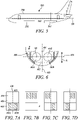
- Figure 6 shows a transverse cross-section through a lower portion of the fuselage of a first example aircraft of the invention, the portion defining a cargo space 450.
- the aircraft has a format similar to any of the aircraft 100, 200, 300 of Figures 1, 3 and 5 respectively.
- the cross-section includes a forward cargo bay 402 containing two like, generally cylindrical hydrogen storage tanks 410A, 410B.
- the tanks 410A, 410B are cylindrical with domed (e.g. hemispherical) ends.
- a vertical plane 420 through the longitudinal axis 401 of the fuselage of the aircraft divides the forward cargo bay into two like lateral portions, each hydrogen storage tank 410A, 41B being located in a respective lateral portion.
- the longitudinal axes 411A, 411B of the hydrogen storage tanks 410A, 410B are generally parallel to the central longitudinal axis 401 of the fuselage of the aircraft and lie in a plane 495 which is orthogonal to the plane 420 and which extends across the with dimension (x) of the cargo bay 402.
- the hydrogen storage tanks 410A, 410B are substantially identical, each having a diameter of 1.0m or 1.1m, or a diameter substantially equal to the height h of the cargo bay 402.
- the aspect ratio R (i.e. length/diameter) of the hydrogen storage tanks 410A, 410B may be in the range 4.2 ⁇ R ⁇ 7.7 so that the length of the tanks may be equal to the length of the cargo bay 402.
- Figure 7A shows a horizontal longitudinal cross-section through the cargo bay 402 in the plane 495.
- the aircraft has a rear cargo bay 404 available for payloads such as baggage and freight.
- the aircraft comprises a hydrogen-fuelled propulsion system (for example one or more PEM fuel cells, one or more hydrogen-fuelled gas turbine engines or a combination of one or more fuel-cells and one or more gas turbine engines) and a conveying system arranged to convey hydrogen from the hydrogen storage tanks to the propulsion system.
- a hydrogen-fuelled propulsion system for example one or more PEM fuel cells, one or more hydrogen-fuelled gas turbine engines or a combination of one or more fuel-cells and one or more gas turbine engines
- a conveying system arranged to convey hydrogen from the hydrogen storage tanks to the propulsion system.
- FIGS 7B - 7D show alternative locations for the hydrogen fuel tanks in other examples of the invention. Both tanks may be located in the rear cargo bay ( Figure 7B ), or alternatively one tank may be in the forward cargo bay and one in the rear cargo bay ( Figures 7C and 7D ), although in all cases each tank is located on a respective lateral side of the plane 420.
- Figure 8 shows a transverse cross-section through a lower portion of the fuselage of a second example aircraft of the invention, the portion defining a cargo space 550 which includes a forward cargo bay 502.
- the aircraft has a general format similar to that of any of the aircraft 100, 200, 300 of Figures 1, 3 and 5 .
- the forward cargo bay 502 contains seven hydrogen storage tanks 510A-G, the longitudinal axes 511A-G of the tanks being substantially parallel to the central longitudinal axis 501 of the fuselage of the aircraft.
- a first set of three tanks 510A-C is arranged such the tanks' longitudinal axes 511A-C lie in a first plane 595 extending across the width dimension (x) of the forward cargo bay 502.
- a second set of four tanks 510D-G is arranged such that the tanks' longitudinal axes 511D-G lie in a second plane 597 extending across the width of the forward cargo bay 502, the second plane 597 being disposed vertically above the first plane 595.
- Any given tank of the first set has a longitudinal axis which has a position x across the width of the cargo bay 502 which is in between the positions of the longitudinal axes of two adjacent tanks in the second set.
- tank 510A has a longitudinal axis 511A located in the x direction between the positions of longitudinal axes 511D, 511E of tanks 510D, 510E respectively.
- the seven tanks 510A-G within the forward cargo bay 502 have a common aspect ratio R in the range 75 ⁇ R ⁇ 15.4 and a common diameter d in the range 0.5 ⁇ d ⁇ 0.63.
- the length of the tanks may be equal to the length of the cargo bay 502.
- the seven hydrogen storage tanks 510A-G may be located in a rear cargo bay of the aircraft.
- the hydrogen storage tanks 510A-G within the cargo bay 502 are distributed symmetrically about a vertical plane 520 passing through the central longitudinal axis 501 of the aircraft, so that their centre of gravity lies in or near the plane 520.
- Further hydrogen storage tanks may be located elsewhere in or on the aircraft, the centre of gravity of any such tanks lying in the plane 520.
- the aircraft comprises a hydrogen-fuelled propulsion system and a conveying system arranged to convey hydrogen from the hydrogen storage tanks to the propulsion system.
- the maximum width of the cargo bay 502 is 8r and the height of the cargo bay 502 is 3.732r, where r is the outer radius of the hydrogen storage tanks.
- Figure 9 shows a transverse cross-section through a lower portion of the fuselage of a third example aircraft of the invention, the portion defining a cargo space 650 which includes a forward cargo bay 602.
- the aircraft has a general format similar to that of any of the aircraft 100, 200, 300 of Figures 1, 3 and 5 .
- the forward cargo bay 602 contains thirteen hydrogen storage tanks 610A-M, the longitudinal axes 611A-M of the tanks being substantially parallel to the central longitudinal axis 601 of the fuselage of the aircraft.
- a first set of four tanks 610A-D is arranged such that the tanks' longitudinal axes 611A-D lie in a plane 695 extending across the width dimension (x) of the forward cargo bay 602.
- each of a second set of five tanks 610E-I lie in a plane 697 which extends across the width dimension of the cargo bay 602, the plane 697 being parallel to and vertically above the plane 695.
- a third set of four tanks 610J-M is arranged such the longitudinal axes 611J-M of the tanks lie in a third plane 699 extending across the width dimension of the cargo bay 602, the plane 699 being parallel to the planes 695, 697 and vertically above the plane 697.
- any given tank of the first or third sets of tanks has a longitudinal axis which has a position across the width dimension (x) of the cargo bay 602 which is in between the positions of the longitudinal axes of a pair of adjacent tanks in the second set.
- tanks 610A, 610J have respective longitudinal axes 611A, 611J located between the positions of the longitudinal axes 611E, 611F of tanks 610E, 610F of the second set of tanks.
- the thirteen hydrogen storage tanks may be located in a rear cargo bay of the aircraft.
- the hydrogen storage tanks within the cargo bay 602 are distributed symmetrically about a vertical plane 620 passing through the central longitudinal axis 601 of the aircraft so that the centre of gravity of the tanks lies in or near the plane 620.
- the tanks 610A-M may have an aspect ratio R in the range 10.4 ⁇ R ⁇ 25.7.
- the diameter d of the tanks 610A-M may be in the range 0.3 ⁇ d ⁇ 0.44.
- the maximum width of the cargo bay 502 is 10r and the height of the cargo bay 502 is 5.464r, where r is radius of the hydrogen storage tanks.
- Tanks of the Figure 6 arrangement have a larger diameter than those of the Figure 8 arrangement, and tanks of the Figure 8 arrangement have a larger diameter than those of the Figure 9 arrangement for a given size of cargo bay.
- Tank packing fraction i.e. the fraction of cargo bay volume occupied by hydrogen storage tanks
- the volume of a cargo bay occupied by stored hydrogen may be increased further by taking advantage of the possibility of reduced tank wall thickness as tank diameter is reduced.
- overall tank stiffness decreases. A long, thin composite tank of relatively small wall thickness may therefore need to be supported to prevent tank flexing and resulting damage to the brittle matrix of the composite material of the tank.
- a further alternative embodiment of the invention employs an arrangement similar to that of Figure 8 but with the tanks distributed differently between forward and rear cargo bays.
- the rear cargo bay may accommodate four tanks and the forward cargo bay accommodate three tanks.
- the distribution of the hydrogen tanks preferably remains symmetric with respect to the plane 520.
- the arrangements of hydrogen storage tanks shown in Figures 8 and 9 may each include an in-situ or common manifold arrangement allowing the number of tanks to be varied simply by removing some of the hydrogen storage tanks, with the rest of the tanks remaining operatively coupled to the hydrogen-fuelled propulsion system of the aircraft. This allows for the respective volumes of a cargo bay occupied by fuel and luggage or freight to be adjusted or traded-off in order to meet the requirements of a particular flight mission or flight profile.
- An in-situ manifold arrangement allows tanks to be inserted or removed without making further adjustments to the fuel system of an aircraft and allows an optimum balance between range and payload to be achieved for a given flight mission.
Landscapes
- Engineering & Computer Science (AREA)
- Aviation & Aerospace Engineering (AREA)
- Mechanical Engineering (AREA)
- General Engineering & Computer Science (AREA)
- Filling Or Discharging Of Gas Storage Vessels (AREA)
Abstract
Description
- The invention relates to aircraft comprising hydrogen storage tanks, particularly hydrogen storage tanks containing gaseous hydrogen or suitable for containing gaseous hydrogen.
- Hydrogen in either gaseous or liquid form is of increasing interest as a fuel for a variety of transport applications, including aeronautical applications, due to an absence of CO2 generation at the point of use. However, storage of gaseous hydrogen at high pressure presents a significant technical challenge and in particular requires a significant increase in the volume of stored fuel compared to that required for traditional fuel. Minimising the loss of useful space within an aircraft and maximising the amount of stored hydrogen are important considerations in relation to retro-fitting known aircraft with hydrogen storage tanks, or in designing new aircraft having conventional fuselage and wing forms.
- According to the invention, an aircraft comprises a hydrogen-fuelled propulsion system, a plurality of like generally cylindrical hydrogen storage tanks, and a conveying system arranged to convey hydrogen from the hydrogen storage tanks to the hydrogen-fuelled propulsion system, the aircraft further comprising a fuselage having a cargo bay including one or more of the plurality of hydrogen storage tanks, the longitudinal axes of the one or more hydrogen storage tanks within the cargo bay extending parallel to the longitudinal axis of the fuselage and lying in one or more planes extending across the width dimension of the cargo bay, and wherein the hydrogen storage tanks within the cargo bay have a common aspect ratio R in the range 4.2 ≤ R ≤ 25.7. Where the aircraft has the format of one of number of known aircraft, for example a format like that of the Airbus® A320®, the volume of the cargo bay which is occupied by the hydrogen storage tanks it contains is maximised or approximately maximised.
- The cargo bay may include exactly two hydrogen storage tanks having a common aspect ratio R in the range 4.2 ≤ R ≤ 7.7, each hydrogen storage tank being disposed on a respective lateral side of a vertical plane which passes through the central longitudinal axis of the fuselage and bisects the cargo bay. The hydrogen storage tanks may have a common diameter d in the range 1.0m ≤ d ≤ 1.1m. The cargo bay may be either a forward or rear cargo bay of the aircraft.
- The fuselage of the aircraft may have a forward cargo bay and rear cargo bay, each being bisected by a vertical plane passing through the central longitudinal axis of the fuselage, with the forward and rear cargo bays each including exactly one hydrogen storage tank, each hydrogen storage tank being located on a respective lateral side of the vertical plane and having an aspect ratio R in the range 4.2 ≤ R ≤ 7.7. This allows the weight of the hydrogen storage tanks to be more evenly distributed along the length of the aircraft whilst keeping the centre of gravity of the tanks within or near the vertical plane passing through the central longitudinal axis of the fuselage. The hydrogen storage tanks may optionally also have a common diameter d in the range 1.0m≤d≤1.1m.
- The cargo bay may include exactly seven like generally cylindrical hydrogen storage tanks arranged in a first set of three tanks and second set of four tanks, longitudinal axes of hydrogen storage tanks of the first and second sets lying in first and second planes respectively which extend across the width dimension of the cargo bay, the second plane being disposed vertically above the first plane, and the longitudinal axis of any given hydrogen storage tank of the first set having a position across the width of the cargo bay between the positions of the longitudinal axes of two adjacent hydrogen storage tanks of the second set. In this case, the hydrogen storage tanks may have a common aspect ratio R having a value in the range 7.5 ≤ R ≤ 15.4, and optionally also a common diameter d in the range 0.5 ≤ d ≤ 0.63. The seven tanks within the cargo bay are preferably distributed symmetrically about a vertical plane which passes through the central longitudinal axis of the fuselage and bisects the cargo bay so that their centre of gravity lies in or near that plane.
- The cargo bay may include exactly thirteen like hydrogen storage tanks arranged in a first set of four tanks, a second set of five tanks and a third set of four tanks, the longitudinal axes of the hydrogen storage tanks of the first, second sets and third sets lying in first, second and third planes respectively which extend across the width dimension of the cargo bay, the second plane being disposed vertically above the first plane and the third plane being disposed vertically above the second plane, the longitudinal axis of any given hydrogen storage tank of the first and third sets having a position across the width of the cargo bay between the positions of the longitudinal axes of two adjacent tanks of the second set. In this case the hydrogen storage tanks may have a common aspect ratio having a value R in the range 10.4 ≤ R ≤ 25.7 and optionally also a common diameter d in the range 0.3 ≤ d ≤ 0.44. Preferably, the thirteen tanks within the cargo bay are distributed symmetrically about a vertical plane which passes through the central longitudinal axis of the fuselage and bisects the cargo bay, so the centre of gravity of the tanks lies in or near that plane.
- The conveying system preferably comprises a manifold system providing for one or more of the hydrogen storage tanks within a cargo bay to be removed from the cargo bay such that the remaining hydrogen storage tanks within the cargo bay remain operatively coupled to the hydrogen-fuelled propulsion system. This provides an aircraft in which the hydrogen fuel capacity and payload may be optimised for a given flight mission or flight profile.
- Embodiments of the invention are described below by way of example only and with reference to the accompanying drawings in which:
- Figure 1
- is a side elevation of a first aircraft of a known type;
- Figure 2
- is a longitudinal cross-section of the fuselage of the
Figure 1 aircraft; - Figure 3
- is a longitudinal cross-section of the fuselage of a second aircraft of a known type;
- Figure 4
- is a transverse cross-section of a lower portion of the fuselage of the
Figure 1 aircraft; - Figure 5
- is a side elevation of a third aircraft of a known type;
- Figure 6
- is a transverse cross-section of a lower portion of the fuselage of a first example aircraft of the invention;
- Figures 7A-D
- show alternative distributions of a pair of hydrogen storage tanks within the first example aircraft of the invention;
- Figure 8
- is a transverse cross-section of a lower portion of the fuselage of a second example aircraft of the invention; and
- Figure 9
- is a transverse cross-section of a lower portion of the fuselage of a third example aircraft of the invention.
- Referring to
Figures 1, 2 and 4 , anaircraft 100 of known type (e.g. an Airbus® A320® or similar aircraft) comprises afuselage 180 having centrallongitudinal axis 101. Thefuselage 180 is divided longitudinally into a passenger space (not shown) and acargo space 150 located vertically below the passenger space. Thecargo space 150 includes aforward cargo bay 102 and arear cargo bay 104 located respectively fore and aft of thewing centre structure 103 of theaircraft 100. Avertical plane 120 passing through the centrallongitudinal axis 101 of thefuselage 180 of theaircraft 100 divides each of thecargo spaces plane 120. The forward andrear cargo bays -
Figure 3 shows a horizontal longitudinal cross-section through thefuselage 280 of asecond aircraft 200 of a known type (e.g. an Airbus® A321® or similar aircraft). Thefuselage 280 has centrallongitudinal axis 201. Thefuselage 280 is divided longitudinally into a passenger space and a cargo space located vertically below the passenger space. The cargo space has forward andrear cargo bays wing centre structure 203 of theaircraft 200. The forward andrear cargo bays -
Figure 5 shows a side elevation of athird aircraft 300 of a known type (e.g. a Boeing® 737® or similar aircraft) having afuselage 380 with a central longitudinal axis 301, and forward andrear cargo bays wing centre structure 303. Cargo bays of commercial aircraft such as 100, 200, 300 are typically in the region of 4.6m to 7.7m in length. -
Figure 6 shows a transverse cross-section through a lower portion of the fuselage of a first example aircraft of the invention, the portion defining acargo space 450. The aircraft has a format similar to any of theaircraft Figures 1, 3 and5 respectively. The cross-section includes aforward cargo bay 402 containing two like, generally cylindricalhydrogen storage tanks 410A, 410B. Thetanks 410A, 410B are cylindrical with domed (e.g. hemispherical) ends. Avertical plane 420 through thelongitudinal axis 401 of the fuselage of the aircraft divides the forward cargo bay into two like lateral portions, each hydrogen storage tank 410A, 41B being located in a respective lateral portion. Thelongitudinal axes 411A, 411B of thehydrogen storage tanks 410A, 410B are generally parallel to the centrallongitudinal axis 401 of the fuselage of the aircraft and lie in aplane 495 which is orthogonal to theplane 420 and which extends across the with dimension (x) of thecargo bay 402. Thehydrogen storage tanks 410A, 410B are substantially identical, each having a diameter of 1.0m or 1.1m, or a diameter substantially equal to the height h of thecargo bay 402. The aspect ratio R (i.e. length/diameter) of thehydrogen storage tanks 410A, 410B may be in the range 4.2 ≤ R ≤ 7.7 so that the length of the tanks may be equal to the length of thecargo bay 402.Figure 7A shows a horizontal longitudinal cross-section through thecargo bay 402 in theplane 495. The aircraft has arear cargo bay 404 available for payloads such as baggage and freight. - The aircraft comprises a hydrogen-fuelled propulsion system (for example one or more PEM fuel cells, one or more hydrogen-fuelled gas turbine engines or a combination of one or more fuel-cells and one or more gas turbine engines) and a conveying system arranged to convey hydrogen from the hydrogen storage tanks to the propulsion system.
- The mass of hydrogen storage tanks is much greater than the mass of fuel they may contain, therefore such tanks need to be carefully located within an aircraft in order to ensure that the centre of gravity of the aircraft is not in an unsuitable position. Gaseous hydrogen fuel accounts for only 20% of the total mass of a full hydrogen storage tank.
Figures 7B - 7D show alternative locations for the hydrogen fuel tanks in other examples of the invention. Both tanks may be located in the rear cargo bay (Figure 7B ), or alternatively one tank may be in the forward cargo bay and one in the rear cargo bay (Figures 7C and 7D ), although in all cases each tank is located on a respective lateral side of theplane 420. -
Figure 8 shows a transverse cross-section through a lower portion of the fuselage of a second example aircraft of the invention, the portion defining acargo space 550 which includes aforward cargo bay 502. The aircraft has a general format similar to that of any of theaircraft Figures 1, 3 and5 . Theforward cargo bay 502 contains sevenhydrogen storage tanks 510A-G, thelongitudinal axes 511A-G of the tanks being substantially parallel to the centrallongitudinal axis 501 of the fuselage of the aircraft. A first set of threetanks 510A-C is arranged such the tanks'longitudinal axes 511A-C lie in afirst plane 595 extending across the width dimension (x) of theforward cargo bay 502. A second set of fourtanks 510D-G is arranged such that the tanks'longitudinal axes 511D-G lie in asecond plane 597 extending across the width of theforward cargo bay 502, thesecond plane 597 being disposed vertically above thefirst plane 595. Any given tank of the first set has a longitudinal axis which has a position x across the width of thecargo bay 502 which is in between the positions of the longitudinal axes of two adjacent tanks in the second set. For example,tank 510A has alongitudinal axis 511A located in the x direction between the positions oflongitudinal axes tanks tanks 510A-G within theforward cargo bay 502 have a common aspect ratio R in the range 75 ≤ R ≤ 15.4 and a common diameter d in the range 0.5 ≤ d ≤ 0.63. The length of the tanks may be equal to the length of thecargo bay 502. In an alternative example aircraft of the invention, the sevenhydrogen storage tanks 510A-G may be located in a rear cargo bay of the aircraft. Thehydrogen storage tanks 510A-G within thecargo bay 502 are distributed symmetrically about avertical plane 520 passing through the centrallongitudinal axis 501 of the aircraft, so that their centre of gravity lies in or near theplane 520. - Further hydrogen storage tanks may be located elsewhere in or on the aircraft, the centre of gravity of any such tanks lying in the
plane 520. The aircraft comprises a hydrogen-fuelled propulsion system and a conveying system arranged to convey hydrogen from the hydrogen storage tanks to the propulsion system. - If the hydrogen storage tanks with the
cargo bay 502 are touching, with tanks of the second set (plane 597) spanning the maximum width of the cargo bay, and the first and second set of tanks in contact with the bottom and top of thecargo bay 502 respectively, then the maximum width of thecargo bay 502 is 8r and the height of thecargo bay 502 is 3.732r, where r is the outer radius of the hydrogen storage tanks. -
Figure 9 shows a transverse cross-section through a lower portion of the fuselage of a third example aircraft of the invention, the portion defining acargo space 650 which includes aforward cargo bay 602. The aircraft has a general format similar to that of any of theaircraft Figures 1, 3 and5 . Theforward cargo bay 602 contains thirteen hydrogen storage tanks 610A-M, thelongitudinal axes 611A-M of the tanks being substantially parallel to the centrallongitudinal axis 601 of the fuselage of the aircraft. A first set of four tanks 610A-D is arranged such that the tanks'longitudinal axes 611A-D lie in aplane 695 extending across the width dimension (x) of theforward cargo bay 602. Thelongitudinal axes 611E-I of each of a second set of five tanks 610E-I lie in aplane 697 which extends across the width dimension of thecargo bay 602, theplane 697 being parallel to and vertically above theplane 695. A third set of fourtanks 610J-M is arranged such thelongitudinal axes 611J-M of the tanks lie in athird plane 699 extending across the width dimension of thecargo bay 602, theplane 699 being parallel to theplanes plane 697. Any given tank of the first or third sets of tanks has a longitudinal axis which has a position across the width dimension (x) of thecargo bay 602 which is in between the positions of the longitudinal axes of a pair of adjacent tanks in the second set. For example,tanks 610A, 610J have respectivelongitudinal axes longitudinal axes tanks 610E, 610F of the second set of tanks. In an alternative example aircraft of the invention, the thirteen hydrogen storage tanks may be located in a rear cargo bay of the aircraft. The hydrogen storage tanks within thecargo bay 602 are distributed symmetrically about avertical plane 620 passing through the centrallongitudinal axis 601 of the aircraft so that the centre of gravity of the tanks lies in or near theplane 620. The tanks 610A-M may have an aspect ratio R in the range 10.4 ≤ R ≤ 25.7. The diameter d of the tanks 610A-M may be in the range 0.3 ≤ d ≤ 0.44. - If the hydrogen storage tanks are touching, with tanks of the second set (plane 697) spanning the maximum width of the cargo bay, and the first and third sets of tanks in contact with the bottom and top of the
cargo bay 602 respectively, then the maximum width of thecargo bay 502 is 10r and the height of thecargo bay 502 is 5.464r, where r is radius of the hydrogen storage tanks. - Tanks of the
Figure 6 arrangement have a larger diameter than those of theFigure 8 arrangement, and tanks of theFigure 8 arrangement have a larger diameter than those of theFigure 9 arrangement for a given size of cargo bay. As tank diameter decreases, hoop stress also decreases and therefore the wall thickness of the tanks may be reduced. Tank packing fraction (i.e. the fraction of cargo bay volume occupied by hydrogen storage tanks) increases moving from theFigure 6 arrangement to theFigure 8 arrangement, and from theFigure 8 arrangement to theFigure 9 arrangement due to decreasing tank diameter. The volume of a cargo bay occupied by stored hydrogen may be increased further by taking advantage of the possibility of reduced tank wall thickness as tank diameter is reduced. However, as tank wall thickness reduces at constant tank length, overall tank stiffness decreases. A long, thin composite tank of relatively small wall thickness may therefore need to be supported to prevent tank flexing and resulting damage to the brittle matrix of the composite material of the tank. - As the number of hydrogen storage tanks within a cargo bay increases, interconnection and manifolding of the tanks become more complex, adding weight to an aircraft of the invention. There may therefore be trade-off between the number of hydrogen storage tanks within a cargo bay and the overall weight of an aircraft of the invention.
- A further alternative embodiment of the invention employs an arrangement similar to that of
Figure 8 but with the tanks distributed differently between forward and rear cargo bays. For example, the rear cargo bay may accommodate four tanks and the forward cargo bay accommodate three tanks. However, the distribution of the hydrogen tanks preferably remains symmetric with respect to theplane 520. - The arrangements of hydrogen storage tanks shown in
Figures 8 and 9 may each include an in-situ or common manifold arrangement allowing the number of tanks to be varied simply by removing some of the hydrogen storage tanks, with the rest of the tanks remaining operatively coupled to the hydrogen-fuelled propulsion system of the aircraft. This allows for the respective volumes of a cargo bay occupied by fuel and luggage or freight to be adjusted or traded-off in order to meet the requirements of a particular flight mission or flight profile. An in-situ manifold arrangement allows tanks to be inserted or removed without making further adjustments to the fuel system of an aircraft and allows an optimum balance between range and payload to be achieved for a given flight mission.
Claims (15)
- An aircraft comprising a hydrogen-fuelled propulsion system, a plurality of like generally cylindrical hydrogen storage tanks, and a conveying system arranged to convey hydrogen from the hydrogen storage tanks to the hydrogen-fuelled propulsion system, wherein the aircraft further comprises a fuselage having a cargo bay (402; 502; 602) including one or more (410A, 410B; 510A-G; 610A-M) of the plurality of hydrogen storage tanks, the longitudinal axes (411A, 411B; 511A-G; 611A-M) of the one or more hydrogen storage tanks within the cargo bay extending parallel to the longitudinal axis (401; 501; 601) of the fuselage and lying in one or more planes (495; 595, 597; 695, 697, 699) extending across the width dimension of the cargo bay, and wherein the hydrogen storage tanks within the cargo bay have a common aspect ratio R in the range 4.2 ≤ R ≤ 25.7.
- An aircraft according to claim 1 wherein the cargo bay (402) includes exactly two hydrogen storage tanks (410A, 410B) having a common aspect ratio R in the range 4.2 ≤ R ≤ 7.7, each hydrogen storage tank being disposed on a respective lateral side of a vertical plane (420) which passes through the central longitudinal axis of the fuselage and bisects the cargo bay.
- An aircraft according to claim 2 wherein the hydrogen storage tanks have a common diameter d in the range 1.0m ≤ d ≤ 1.1m.
- An aircraft according to claim 2 or claim 3 wherein the cargo bay is either a forward cargo bay (402) or a rear cargo bay (404).
- An aircraft according to claim 1 wherein the fuselage has a forward cargo bay (402) and rear cargo bay (404) each being bisected by a vertical plane (420) passing through the central longitudinal axis (401) of the fuselage and wherein the forward and rear cargo bays each include exactly one hydrogen storage tank, each hydrogen storage tank being located on a respective lateral side of the vertical plane and having an aspect ratio R in the range 4.2 ≤ R ≤ 7.7.
- An aircraft according to claim 5 wherein the hydrogen storage tanks have a common diameter d in the range 1.0m ≤ d ≤ 1.1m.
- An aircraft according to claim 1 wherein the cargo bay includes exactly seven like generally cylindrical hydrogen storage tanks (510A-G), arranged in a first set of three tanks and second set of four tanks, longitudinal axes (511A-G) of hydrogen storage tanks of the first and second sets lying in first (595) and second (597) planes respectively which extend across the width dimension of the cargo bay, the second plane being disposed vertically above the first plane, and wherein the longitudinal axis of any given hydrogen storage tank of the first set has a position across the width of the cargo bay between the positions of the longitudinal axes of two adjacent hydrogen storage tanks of the second set.
- An aircraft according to claim 7 wherein the hydrogen storage tanks have a common aspect ratio R having a value in the range 7.5 ≤ R ≤ 15.4.
- An aircraft according to claim 8 wherein the hydrogen storage tanks have a common diameter d in the range 0.5 ≤ d ≤ 0.63.
- An aircraft according to any of claims 7 to 9 wherein the seven tanks within the cargo bay are distributed symmetrically about a vertical plane (520) which passes through the central longitudinal axis (501) of the fuselage and bisects the cargo bay.
- An aircraft according to claim 1 wherein the cargo bay includes exactly thirteen like hydrogen storage tanks (610A-M) arranged in a first set of four tanks, a second set of five tanks and a third set of four tanks, the longitudinal axes (611A-M) of the hydrogen storage tanks of the first, second sets and third sets lying in first, second and third planes (695, 697, 699) respectively which extend across the width dimension of the cargo bay, the second plane being disposed vertically above the first plane and the third plane being disposed vertically above the second plane, and wherein the longitudinal axis of any given hydrogen storage tank of the first and third sets has a position across the width of the cargo bay between the positions of the longitudinal axes of two adjacent tanks of the second set.
- An aircraft according to claim 11 wherein the hydrogen storage tanks have a common aspect ratio having a value R in the range 10.4 ≤ R ≤ 25.7.
- An aircraft according to claim 12 wherein the hydrogen storage tanks have a common diameter d in the range 0.3 ≤ d ≤ 0.44.
- An aircraft according to any of claims 11 to 13 wherein the thirteen tanks within the cargo bay are distributed symmetrically about a vertical plane (620) which passes through the central longitudinal axis (601) of the fuselage and bisects the cargo bay.
- An aircraft according to any preceding claim wherein the conveying system comprises a manifold system providing for one or more of the hydrogen storage tanks within a cargo bay to be removed from the cargo bay, the remaining hydrogen storage tanks within the cargo bay remaining operatively coupled to the hydrogen-fuelled propulsion system.
Applications Claiming Priority (1)
| Application Number | Priority Date | Filing Date | Title |
|---|---|---|---|
| GBGB2100664.8A GB202100664D0 (en) | 2021-01-19 | 2021-01-19 | Aircraft comprising hydrogen storage tanks |
Publications (2)
| Publication Number | Publication Date |
|---|---|
| EP4029787A1 true EP4029787A1 (en) | 2022-07-20 |
| EP4029787B1 EP4029787B1 (en) | 2026-02-11 |
Family
ID=74678965
Family Applications (1)
| Application Number | Title | Priority Date | Filing Date |
|---|---|---|---|
| EP21215798.6A Active EP4029787B1 (en) | 2021-01-19 | 2021-12-20 | Aircraft comprising hydrogen storage tanks |
Country Status (3)
| Country | Link |
|---|---|
| US (3) | US11905028B2 (en) |
| EP (1) | EP4029787B1 (en) |
| GB (1) | GB202100664D0 (en) |
Cited By (3)
| Publication number | Priority date | Publication date | Assignee | Title |
|---|---|---|---|---|
| CN115071951A (en) * | 2022-07-25 | 2022-09-20 | 中国商用飞机有限责任公司北京民用飞机技术研究中心 | A three-body fusion aircraft |
| FR3138650A1 (en) * | 2022-08-03 | 2024-02-09 | Airbus Operations (S.A.S.) | Aircraft comprising a fuselage reinforced by a ventral beam and provided with at least one opening closed by a removable panel |
| WO2025168177A1 (en) * | 2024-02-09 | 2025-08-14 | MTU Aero Engines AG | Heat exchanger - storage tank assembly for an aircraft |
Families Citing this family (1)
| Publication number | Priority date | Publication date | Assignee | Title |
|---|---|---|---|---|
| US12601299B1 (en) | 2025-04-16 | 2026-04-14 | General Electric Company | Hydrogen fuel system for an aircraft |
Citations (2)
| Publication number | Priority date | Publication date | Assignee | Title |
|---|---|---|---|---|
| US20140117163A1 (en) * | 2012-10-31 | 2014-05-01 | General Electric Company | Cryogenic tank |
| US20160033083A1 (en) * | 2014-08-04 | 2016-02-04 | Washington State University | Vapor Cooled Shielding Liner for Cryogenic Storage in Composite Pressure Vessels |
Family Cites Families (15)
| Publication number | Priority date | Publication date | Assignee | Title |
|---|---|---|---|---|
| US20040129836A1 (en) * | 2002-09-10 | 2004-07-08 | The Boeing Company | Liquid hydrogen fueled aircraft |
| US7051979B2 (en) | 2004-01-29 | 2006-05-30 | The Boeing Company | Auxiliary fuel tank systems for aircraft and methods for their manufacture and use |
| US7624946B2 (en) * | 2004-03-30 | 2009-12-01 | Airbus Deutschland Gmbh | Reservoir for cryogenic fuels and vehicles |
| US7871042B2 (en) * | 2006-11-14 | 2011-01-18 | The Boeing Company | Hydrogen fueled blended wing body ring tank |
| EP2224519A1 (en) * | 2009-02-16 | 2010-09-01 | HyET Holding B.V. | Hydrogen storage vessel and fuel cell apparatus comprising an ionic decompression cell |
| US8851424B2 (en) | 2010-05-06 | 2014-10-07 | Embraer S.A. | Systems and methods to provide compliance with structural load requirements for aircraft with additional fuel tankage |
| CA2878530C (en) * | 2012-07-26 | 2021-01-26 | Zodiac Aerotechnics | Removable storage for hydrogen on-board passenger transport vehicles such as aircraft |
| US10800525B2 (en) | 2013-05-20 | 2020-10-13 | The Boeing Company | Efficient low carbon emission airplane integrating jet fuel and cryogenic fuel systems |
| DE102014107316A1 (en) | 2014-05-23 | 2015-11-26 | Airbus Operations Gmbh | Tank system for the cryogenic storage of hydrogen and aircraft with a tank system for the cryogenic storage of hydrogen |
| CN207712306U (en) | 2017-12-26 | 2018-08-10 | 中国空气动力研究与发展中心高速空气动力研究所 | A kind of hydrogen fuel aircraft |
| CN107972877B (en) | 2017-12-26 | 2024-03-15 | 中国空气动力研究与发展中心高速空气动力研究所 | Hydrogen fuel aircraft |
| FR3096029A1 (en) * | 2019-09-16 | 2020-11-20 | Airbus | AIRCRAFT CONTAINING HYDROGEN TANKS |
| US11643204B2 (en) | 2019-12-09 | 2023-05-09 | Arizona Board Of Regents On Behalf Of Arizona State University | Unmanned aerial vehicle for low-pressure hydrogen transport |
| EP4149794A4 (en) | 2020-05-12 | 2024-05-29 | Universal Hydrogen Co. | Systems and methods for storing, transporting, and using hydrogen |
| US11796132B2 (en) * | 2020-12-02 | 2023-10-24 | Green Grid Inc. | Hydrogen fuel storage and delivery system |
-
2021
- 2021-01-19 GB GBGB2100664.8A patent/GB202100664D0/en not_active Ceased
- 2021-12-20 EP EP21215798.6A patent/EP4029787B1/en active Active
- 2021-12-27 US US17/562,775 patent/US11905028B2/en active Active
-
2023
- 2023-03-22 US US18/187,830 patent/US20230249840A1/en not_active Abandoned
- 2023-03-22 US US18/187,818 patent/US20230219695A1/en not_active Abandoned
Patent Citations (2)
| Publication number | Priority date | Publication date | Assignee | Title |
|---|---|---|---|---|
| US20140117163A1 (en) * | 2012-10-31 | 2014-05-01 | General Electric Company | Cryogenic tank |
| US20160033083A1 (en) * | 2014-08-04 | 2016-02-04 | Washington State University | Vapor Cooled Shielding Liner for Cryogenic Storage in Composite Pressure Vessels |
Non-Patent Citations (2)
| Title |
|---|
| DIETL TOBIAS ET AL: "Polaris Future Aircraft Design Concept", 1 July 2018 (2018-07-01), pages 1 - 38, XP055918589, Retrieved from the Internet <URL:https://www.dlr.de/content/en/downloads/2018/university-of-stuttgart-polaris-future-aircraft-design-concept_3098.pdf?__blob=publicationFile&v=10> [retrieved on 20220506] * |
| GARDINER GINGER: "Carbon fiber in pressure vessels for hydrogen | CompositesWorld", 23 October 2020 (2020-10-23), pages 1 - 15, XP055918568, Retrieved from the Internet <URL:https://www.compositesworld.com/articles/cfrp-pressure-vessels-for-hydrogen> [retrieved on 20220506] * |
Cited By (3)
| Publication number | Priority date | Publication date | Assignee | Title |
|---|---|---|---|---|
| CN115071951A (en) * | 2022-07-25 | 2022-09-20 | 中国商用飞机有限责任公司北京民用飞机技术研究中心 | A three-body fusion aircraft |
| FR3138650A1 (en) * | 2022-08-03 | 2024-02-09 | Airbus Operations (S.A.S.) | Aircraft comprising a fuselage reinforced by a ventral beam and provided with at least one opening closed by a removable panel |
| WO2025168177A1 (en) * | 2024-02-09 | 2025-08-14 | MTU Aero Engines AG | Heat exchanger - storage tank assembly for an aircraft |
Also Published As
| Publication number | Publication date |
|---|---|
| US20230249840A1 (en) | 2023-08-10 |
| US11905028B2 (en) | 2024-02-20 |
| EP4029787B1 (en) | 2026-02-11 |
| GB202100664D0 (en) | 2021-03-03 |
| US20220281615A1 (en) | 2022-09-08 |
| US20230219695A1 (en) | 2023-07-13 |
Similar Documents
| Publication | Publication Date | Title |
|---|---|---|
| US11905028B2 (en) | Aircraft comprising hydrogen storage tanks | |
| EP4029786B1 (en) | Aircraft with hydrogen storage tanks | |
| EP2848520B1 (en) | Cryogenic fuel tanks for use in aircraft structures | |
| US20150336680A1 (en) | Tank System For The Cryogenic Storage Of Hydrogen, And Aircraft With A Tank System For The Cryogenic Storage Of Hydrogen | |
| US8851424B2 (en) | Systems and methods to provide compliance with structural load requirements for aircraft with additional fuel tankage | |
| CN101903242B (en) | Fuel Cell System Module | |
| US6123295A (en) | Fuel tank for lifting body re-entry vehicle | |
| WO2021148335A1 (en) | An aircraft fuselage | |
| EP4124568A1 (en) | Aircraft with hydrogen tank | |
| CN106628114A (en) | Integrated unmanned aerial vehicle wing | |
| US20080230654A1 (en) | Hydrogen fueled blended wing body ring tank | |
| EP4112478B1 (en) | Fuselage section of an aircraft, aircraft fuselage, and aircraft | |
| EP4455017A1 (en) | Fuel tank for aircraft, processor of aircraft, and aircraft | |
| CN217125165U (en) | A satellite power cabin structure capable of carrying large-capacity propellant | |
| EP4477558B1 (en) | An aircraft fuselage section | |
| Tam et al. | Conceptual design of space efficient tanks | |
| EP4574674A1 (en) | Aircraft with fuel tank | |
| EP4124577B1 (en) | Modular aircraft tank, tank system, aircraft and operation method | |
| Stautner et al. | Cryotankage—Tank Shapes and Airframe Integration | |
| EP4660080A1 (en) | Fuel tank of or for an aircraft, and aircraft with fuel tank | |
| Cho et al. | Structural design and analysis of a BWB military cargo transport fuselage | |
| Gavrilovic et al. | Ground testing and analysis of a liquid-hydrogen propulsion system for UAVs | |
| WO2020202237A1 (en) | Airship with rigid supporting structure | |
| Tyler Jr | Maximizing the physical capacity of a fleet of aircraft and containers handling mixed freight | |
| Mockelman et al. | Conceptual Design Studies of Fuel Cell Powered Unmanned Aircraft for Long Loiter |
Legal Events
| Date | Code | Title | Description |
|---|---|---|---|
| PUAI | Public reference made under article 153(3) epc to a published international application that has entered the european phase |
Free format text: ORIGINAL CODE: 0009012 |
|
| STAA | Information on the status of an ep patent application or granted ep patent |
Free format text: STATUS: THE APPLICATION HAS BEEN PUBLISHED |
|
| AK | Designated contracting states |
Kind code of ref document: A1 Designated state(s): AL AT BE BG CH CY CZ DE DK EE ES FI FR GB GR HR HU IE IS IT LI LT LU LV MC MK MT NL NO PL PT RO RS SE SI SK SM TR |
|
| STAA | Information on the status of an ep patent application or granted ep patent |
Free format text: STATUS: REQUEST FOR EXAMINATION WAS MADE |
|
| 17P | Request for examination filed |
Effective date: 20221114 |
|
| RBV | Designated contracting states (corrected) |
Designated state(s): AL AT BE BG CH CY CZ DE DK EE ES FI FR GB GR HR HU IE IS IT LI LT LU LV MC MK MT NL NO PL PT RO RS SE SI SK SM TR |
|
| STAA | Information on the status of an ep patent application or granted ep patent |
Free format text: STATUS: EXAMINATION IS IN PROGRESS |
|
| 17Q | First examination report despatched |
Effective date: 20230915 |
|
| GRAP | Despatch of communication of intention to grant a patent |
Free format text: ORIGINAL CODE: EPIDOSNIGR1 |
|
| STAA | Information on the status of an ep patent application or granted ep patent |
Free format text: STATUS: GRANT OF PATENT IS INTENDED |
|
| INTG | Intention to grant announced |
Effective date: 20251126 |
|
| GRAS | Grant fee paid |
Free format text: ORIGINAL CODE: EPIDOSNIGR3 |
|
| GRAA | (expected) grant |
Free format text: ORIGINAL CODE: 0009210 |
|
| STAA | Information on the status of an ep patent application or granted ep patent |
Free format text: STATUS: THE PATENT HAS BEEN GRANTED |
|
| P01 | Opt-out of the competence of the unified patent court (upc) registered |
Free format text: CASE NUMBER: UPC_APP_0017827_4029787/2025 Effective date: 20251216 |
|
| AK | Designated contracting states |
Kind code of ref document: B1 Designated state(s): AL AT BE BG CH CY CZ DE DK EE ES FI FR GB GR HR HU IE IS IT LI LT LU LV MC MK MT NL NO PL PT RO RS SE SI SK SM TR |
|
| REG | Reference to a national code |
Ref country code: CH Ref legal event code: F10 Free format text: ST27 STATUS EVENT CODE: U-0-0-F10-F00 (AS PROVIDED BY THE NATIONAL OFFICE) Effective date: 20260211 Ref country code: GB Ref legal event code: FG4D |
|
| REG | Reference to a national code |
Ref country code: DE Ref legal event code: R096 Ref document number: 602021047651 Country of ref document: DE |
|
| REG | Reference to a national code |
Ref country code: IE Ref legal event code: FG4D |