EP4029782B1 - Doppelfunktions aktivierungsschalter und modusauswahlsystem für auswurfsysteme - Google Patents
Doppelfunktions aktivierungsschalter und modusauswahlsystem für auswurfsysteme Download PDFInfo
- Publication number
- EP4029782B1 EP4029782B1 EP22150225.5A EP22150225A EP4029782B1 EP 4029782 B1 EP4029782 B1 EP 4029782B1 EP 22150225 A EP22150225 A EP 22150225A EP 4029782 B1 EP4029782 B1 EP 4029782B1
- Authority
- EP
- European Patent Office
- Prior art keywords
- controller
- arm switch
- switch assembly
- mode
- ejection
- Prior art date
- Legal status (The legal status is an assumption and is not a legal conclusion. Google has not performed a legal analysis and makes no representation as to the accuracy of the status listed.)
- Active
Links
Images


Classifications
-
- B—PERFORMING OPERATIONS; TRANSPORTING
- B64—AIRCRAFT; AVIATION; COSMONAUTICS
- B64D—EQUIPMENT FOR FITTING IN OR TO AIRCRAFT; FLIGHT SUITS; PARACHUTES; ARRANGEMENT OR MOUNTING OF POWER PLANTS OR PROPULSION TRANSMISSIONS IN AIRCRAFT
- B64D25/00—Emergency apparatus or devices, not otherwise provided for
- B64D25/08—Ejecting or escaping means
- B64D25/10—Ejector seats
-
- B—PERFORMING OPERATIONS; TRANSPORTING
- B60—VEHICLES IN GENERAL
- B60N—SEATS SPECIALLY ADAPTED FOR VEHICLES; VEHICLE PASSENGER ACCOMMODATION NOT OTHERWISE PROVIDED FOR
- B60N2/00—Seats specially adapted for vehicles; Arrangement or mounting of seats in vehicles
- B60N2/24—Seats specially adapted for vehicles; Arrangement or mounting of seats in vehicles for particular purposes or particular vehicles
- B60N2/42—Seats specially adapted for vehicles; Arrangement or mounting of seats in vehicles for particular purposes or particular vehicles the seat constructed to protect the occupant from the effect of abnormal g-forces, e.g. crash or safety seats
- B60N2/427—Seats or parts thereof displaced during a crash
- B60N2/42772—Seats or parts thereof displaced during a crash characterised by the triggering system
- B60N2/42781—Seats or parts thereof displaced during a crash characterised by the triggering system mechanical triggering
-
- G—PHYSICS
- G05—CONTROLLING; REGULATING
- G05B—CONTROL OR REGULATING SYSTEMS IN GENERAL; FUNCTIONAL ELEMENTS OF SUCH SYSTEMS; MONITORING OR TESTING ARRANGEMENTS FOR SUCH SYSTEMS OR ELEMENTS
- G05B19/00—Program-control systems
- G05B19/02—Program-control systems electric
- G05B19/04—Program control other than numerical control, i.e. in sequence controllers or logic controllers
- G05B19/042—Program control other than numerical control, i.e. in sequence controllers or logic controllers using digital processors
- G05B19/0428—Safety, monitoring
-
- B—PERFORMING OPERATIONS; TRANSPORTING
- B64—AIRCRAFT; AVIATION; COSMONAUTICS
- B64D—EQUIPMENT FOR FITTING IN OR TO AIRCRAFT; FLIGHT SUITS; PARACHUTES; ARRANGEMENT OR MOUNTING OF POWER PLANTS OR PROPULSION TRANSMISSIONS IN AIRCRAFT
- B64D11/00—Passenger or crew accommodation; Flight-deck installations not otherwise provided for
- B64D11/06—Arrangements of seats, or adaptations or details specially adapted for aircraft seats
- B64D11/0616—Arrangements of seats, or adaptations or details specially adapted for aircraft seats with ejection means
-
- B—PERFORMING OPERATIONS; TRANSPORTING
- B64—AIRCRAFT; AVIATION; COSMONAUTICS
- B64D—EQUIPMENT FOR FITTING IN OR TO AIRCRAFT; FLIGHT SUITS; PARACHUTES; ARRANGEMENT OR MOUNTING OF POWER PLANTS OR PROPULSION TRANSMISSIONS IN AIRCRAFT
- B64D11/00—Passenger or crew accommodation; Flight-deck installations not otherwise provided for
- B64D11/06—Arrangements of seats, or adaptations or details specially adapted for aircraft seats
- B64D11/0689—Arrangements of seats, or adaptations or details specially adapted for aircraft seats specially adapted for pilots
Definitions
- Ejection systems are designed to expel ejection seats and their occupants from an aircraft.
- Some aircraft include a two-seat ejection system, wherein a pilot ejection seat and a co-pilot ejection seat are expelled from the aircraft.
- Current two-seat ejection systems generally include an ejection mode select system, which allows a flight crew member to manually select which ejection seats will be ejected upon deployment of the ejection system and whether initiation of the eject sequence by the co-pilot ejection seat will also initiate deployment of the pilot ejection seat.
- An incorrect ejection mode selection can lead to injury and/or death if an ejection seat is not ejected before impact.
- US 2017/297725 A1 discloses a system for selecting an ejection mode on an aircraft which includes an egress actuator, a ballistic signal system operatively connected to the egress actuator, and a processor operatively connected to the ballistic signal system and the egress actuator.
- the processor is configured to receive a flight characteristic from an aircraft controller, and select, based on the flight characteristic, an ejection mode from two ejection modes.
- the processor is further configured to receive a pilot egress command and transmit a signal to actuate the ejection mode from the two ejection modes.
- the dual switch arm and mode select system comprises a controller and an ejection mode selector in communication with the controller.
- a first arm switch assembly is in communication with the controller.
- the first arm switch assembly is configured to translate between a safe position and an armed position.
- a second arm switch assembly is in communication with the controller.
- the second arm switch assembly is configured to translate between the safe position and the armed position.
- a display is in communication with the controller.
- a tangible, non-transitory medium is configured to communicate with the controller.
- the tangible, non-transitory medium has instructions stored thereon that, in response to execution by the controller, cause the controller to perform operations, which comprise determining, by the controller, an ejection mode of the ejection system based on a signal received from the ejection mode selector; determining, by the controller, a position of the first arm switch assembly; determining, by the controller, a position of the second arm switch assembly; and commanding, by the controller, the display to output at least one of a fault-free signal, a fault signal, or a warning signal based on the ejection mode, the position of the first arm switch assembly, and the position of the second arm switch assembly.
- the ejection mode may comprise at least one of a solo mode, a dual mode, or a pilot command mode.
- the controller may be configured to command a first indicator of the display to output the fault-free signal in response to the controller determining the ejection mode is the solo mode, the first arm switch assembly is in the armed position, and the second arm switch assembly is in the safe position.
- the controller may be configured to command the first indicator of the display to output the fault signal in response to the controller determining the ejection mode is the solo mode and at least one of the first arm switch assembly is in the safe position or the second arm switch assembly is in the armed position.
- the controller may be configured to command a second indicator of the display to output the warning signal in response to the controller determining the ejection mode is the dual mode, the first arm switch assembly is in the armed position, and the second arm switch assembly is in the armed position.
- the controller may be configured to command the second indicator of the display to output the fault signal in response to the controller determining the ejection mode is the dual mode and at least one of the first arm switch assembly or the second arm switch assembly is in the safe position.
- the controller may be configured to command a third indicator of the display to output the warning signal in response to the controller determining the ejection mode is the pilot command mode, the first arm switch assembly is in the armed position, and the second arm switch assembly is in the armed position.
- the controller may be configured to command the third indicator of the display to output the fault signal in response to the controller determining the ejection mode is the pilot command mode and at least one of the first arm switch assembly or the second arm switch assembly is in the safe position.
- the controller may be configured to command a first seat indicator of the display to output an armed signal in response to the controller determining the first arm switch assembly is in the armed position.
- the controller may be configured to command a second seat indicator of the display to output the armed signal in response to the controller determining the second arm switch assembly is in the armed position.
- the first arm switch assembly may comprise a lever and a circuit assembly.
- the circuit assembly may be configured to output an arm switch position signal to the controller.
- determining, by the controller, the position of the first arm switch assembly may comprise receiving, by the controller, the arm switch position signal, from the circuit assembly; and determining, by the controller, if the first arm switch assembly is in the armed position or the safe position based on the arm switch position signal.
- a method for monitoring an ejection mode selection for an ejection system comprises determining, by a controller, an ejection mode of the ejection system; and determining, by the controller, a position of a first arm switch assembly of a first ejection seat.
- the position of the first arm switch assembly is at least one of an armed position or a safe position.
- the method further comprises determining, by the controller, a position of a second arm switch assembly of a second ejection seat, the position of the second arm switch assembly is at least one of the armed position or the safe position; and commanding, by the controller, a display to output at least one of a fault-free signal, a fault signal, or a warning signal based on the ejection mode, the position of the first arm switch assembly, and the position of the second arm switch assembly.
- determining, by the controller, the ejection mode of the ejection system may comprise receiving, by the controller, a signal from an ejection mode selector; and determining, by the controller, if the ejection mode is a solo mode, a dual mode, or a pilot command mode based on the signal from the ejection mode selector.
- commanding, by the controller, the display to output at least one of the fault-free signal, the fault signal, or the warning signal may comprise at least one of commanding, by the controller, an indicator of the display to output the fault-free signal in response to the controller determining the ejection mode is the solo mode, the first arm switch assembly is in the armed position, and the second arm switch assembly is in the safe position; or commanding, by the controller, the indicator of the display to output the fault signal in response to the controller determining the ejection mode is the solo mode and at least one of the first arm switch assembly is in the safe position or the second arm switch assembly is in the armed position.
- commanding, by the controller, the display to output at least one of the fault-free signal, the fault signal, or the warning signal may comprise at least one of commanding, by the controller, an indicator of the display to output the warning signal in response to the controller determining the ejection mode is the dual mode, the first arm switch assembly is in the armed position, and the second arm switch assembly is in the armed position; or commanding, by the controller, the indicator of the display to output the fault signal in response to the controller determining the ejection mode is the dual mode and at least one of the first arm switch assembly or the second arm switch assembly is in the safe position.
- commanding, by the controller, the display to output at least one of the fault-free signal, the fault signal, or the warning signal may comprise at least one of commanding, by the controller, an indicator of the display to output the warning signal in response to the controller determining the ejection mode is the pilot command mode, the first arm switch assembly is in the armed position, and the second arm switch assembly is in the armed position; or commanding, by the controller, the indicator of the display to output the fault signal in response to the controller determining the ejection mode is the pilot command mode and at least one of the first arm switch assembly or the second arm switch assembly is in the safe position.
- the method may further comprise at least one of commanding, by the controller, a first seat indicator of the display to output an armed signal in response to the controller determining the first arm switch assembly is in the armed position; commanding, by the controller, the first seat indicator of the display to output a safe signal in response to the controller determining the first arm switch assembly is in the safe position; commanding, by the controller, a second seat indicator of the display to output the armed signal in response to the controller determining the second arm switch assembly is in the armed position, or commanding, by the controller, the second seat indicator of the display to output the safe signal in response to the controller determining the second arm switch assembly is in the safe position.
- any reference to singular includes plural embodiments, and any reference to more than one component or step may include a singular embodiment or step.
- any reference to attached, fixed, connected or the like may include permanent, removable, temporary, partial, full and/or any other possible attachment option.
- any reference to without contact (or similar phrases) may also include reduced contact or minimal contact. Surface shading lines may be used throughout the figures to denote different parts but not necessarily to denote the same or different materials.
- non-transitory is to be understood to remove only propagating transitory signals per se from the claim scope and does not relinquish rights to all standard computer-readable media that are not only propagating transitory signals per se.
- the dual arm switch and mode select system is configured to determine which of the ejection seats are armed and whether the selected ejection mode agrees with the armed seat determination.
- the dual arm switch and mode select system may send an alert if the selected ejection mode does not agree with the armed seat determination.
- the dual arm switch and mode select system may send an alert if both the pilot seat and the co-pilot seat are armed, but a "solo" mode (i.e., eject pilot seat only mode) is selected.
- an alert may be sent if the co-pilot seat is not armed, but a "both" mode (i.e., an ejection pilot seat and co-pilot seat) is selected.
- the dual arm switch and mode select system may also allow the flight crew to easily determine whether an initiation of the co-pilot ejection sequence will also initiate the pilot ejection sequence.
- dual arm switch and mode select system can improve safety by decreasing the probability for incorrect ejection mode selection, thereby reducing the risk a crew member will not be ejected when he/she should be ejected or that a pilot will be inadvertently ejected.
- Aircraft ejection system 100 may be installed in aircraft 102 to safely expel a pilot (or first) ejection seat 104 and a co-pilot (or second) ejection seat 106 from the cockpit 108 of aircraft 102.
- Pilot ejection seat 104 may be urged from cockpit 108 by a propulsion system 110.
- Co-pilot ejection seat 106 may be urged from cockpit 108 by a propulsion system 112.
- Aircraft 102 may be a passenger aircraft, a cargo aircraft, a military aircraft, or the like.
- ejection system 100 may include a dual arm switch and mode select (DASMS) system 120.
- DASMS system 120 includes a controller 122.
- Controller 122 may include one or more logic devices such as one or more of a central processing unit (CPU), an accelerated processing unit (APU), a digital signal processor (DSP), a field programmable gate array (FPGA), an application specific integrated circuit (ASIC), or the like. Controller 122 further includes any tangible, non-transitory computer-readable storage medium 124 known in the art. The storage medium 124 has instructions stored thereon that, in response to execution by controller 122, cause controller 122 to perform various operations for determining if a correct ejection mode is selected.
- CPU central processing unit
- APU accelerated processing unit
- DSP digital signal processor
- FPGA field programmable gate array
- ASIC application specific integrated circuit
- controller 122 is configured to determine which of pilot ejection seat 104 and co-pilot ejection seat 106 are armed and if the ejection mode (i.e., the current ejection mode) of ejection system 100 is congruous with armed seat determination.
- Controller 122 is in communication (wired communication or wireless communication) with an ejection mode selector 126 of ejection system 100.
- Ejection mode selector 126 is configured to allow a crew member of aircraft 102 to manually select an ejection mode for ejection system 100.
- ejection mode selector 126 may send a signal 127 to controller 122 indicative of the current ejection mode for ejection system 100.
- controller 122 may determine the ejection mode of ejection system 100 based the signal 127 received from ejection mode selector 126.
- ejection mode selector 126 may allow the crew members to select between a "solo ejection mode," a "dual ejection mode,” and a "pilot command mode.”
- solo ejection mode is configured such that initiation of an ejection sequence by pilot ejection seat 104 (e.g., actuation of pilot (or first) ejection handle 128) causes expulsion of only pilot ejection seat 104. Stated differently, when solo ejection mode is selected, actuation of pilot ejection handle 128 does not cause co-pilot ejection seat 106 to deploy.
- Dual ejection mode is configured such that initiation of an ejection sequence by either pilot ejection seat 104 or co-pilot ejection seat 106 (e.g., actuation of either pilot ejection handle 128 or a co-pilot (or second) ejection handle 130) causes expulsion of both pilot ejection seat 104 and co-pilot ejection seat 106.
- pilot ejection seat 104 or co-pilot ejection seat 106 e.g., actuation of either pilot ejection handle 128 or a co-pilot (or second) ejection handle 130
- Pilot command mode is configured such that initiation of an ejection sequence by pilot ejection seat 104 (e.g., actuation of pilot ejection handle 128) causes expulsion of both pilot ejection seat 104 and co-pilot ejection seat 106, while initiation of an ejection sequence by co-pilot ejection seat 106 (e.g., actuation of co-pilot ejection handle 130) causes expulsion of only co-pilot ejection seat 106.
- Ejection mode selector 126 may be a knob, push button(s), switch, touch screen, or any other component capable of allowing a crew member to select one of solo ejection mode, dual ejection mode, or pilot command ejection mode.
- Controller 122 is also in communication with a pilot (or first) arm switch assembly 132 located on pilot ejection seat 104, and a co-pilot (or second) arm switch assembly 134 located on co-pilot ejection seat 106.
- pilot arm switch assembly 132 and co-pilot arm switch assembly 134 are configured to translate between a "safe position" and an "armed position". In FIG. 2 , both pilot arm switch assembly 132 and co-pilot arm switch assembly 134 are shown in the safe position. In the safe position, the ejection seat cannot initiate an ejection sequence.
- pilot arm switch assembly 132 when pilot arm switch assembly 132 is in the safe position, a mechanical lockout assembly operably coupled between pilot arm switch assembly 132 and pilot ejection handle 128 blocks, or otherwise prevents, actuation of pilot ejection handle 128, such that pilot ejection handle 128 will not be able to initiate an ejection sequence for either pilot ejection seat 104 or co-pilot ejection seat 106.
- a mechanical lockout assembly operably coupled between co-pilot arm switch assembly 134 and co-pilot ejection handle 130 blocks, or otherwise prevents, actuation of co-pilot ejection handle 130, such that co-pilot ejection handle 130 will not be able to initiate an ejection sequence for either co-pilot ejection seat 106 or pilot ejection seat 104.
- the ejection seat can initiate the selected ejection mode.
- pilot arm switch assembly 132 when pilot arm switch assembly 132 is in the armed position actuation of pilot ejection handle 128 will initiate an ejection sequence for pilot ejection seat 104 and, if dual ejection mode or pilot command ejection mode is selected, for co-pilot ejection seat 106.
- co-pilot arm switch assembly 134 when co-pilot arm switch assembly 134 is in the armed position, actuation of co-pilot ejection handle 130 will initiate an ejection sequence for co-pilot ejection seat 106 and, if dual ejection mode is selected, for pilot ejection seat 104.
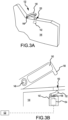
- pilot arm switch assembly 132 is illustrated in the safe position. While FIGs. 3A, 3B , 4A, 4B , 5A and 5B illustrate details of pilot arm switch assembly 132, it is contemplated and understood that co-pilot arm switch assembly, in FIG. 2 , includes the features and functionalities as described herein with reference to pilot arm switch assembly 132.
- Pilot arm switch assembly 132 includes a lever 140 and a circuit assembly 142.
- circuit assembly 142 may be located within a side panel 144 of pilot ejection seat 104.
- Lever 140 may be configured to rotate about a pivot joint 146.
- Lever 140 may include a protrusion 148.
- protrusion 148 may be located outside (e.g., above) an opening 150 defined by side panel 144.
- Controller 122 is in communication with circuit assembly 142. Controller 122 is configured to determine if pilot arm switch assembly 132 is in the safe position or the armed position based on an arm switch position signal received from circuit assembly 142. For example, in various embodiments, in the safe position, a circuit 154 of circuit assembly may be in an open state such that no signal (or a signal indicative of pilot arm switch assembly 132 being in the position) is provided to controller 122. The lack of signal indicates to controller 122 that pilot arm switch assembly 132 is in the safe position.
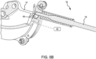
- pilot arm switch assembly 132 is illustrated in the armed position.
- rotation of lever 140 about pivot joint 146 is configured to cause protrusion 148 to translate through opening 150 in side panel 144 and into contact with an arm 152 of circuit assembly 142.
- Rotation of lever 140 may cause protrusion 148 to force arm 152 towards a switch 156 of circuit assembly 142.
- rotating protrusion 148 into opening 150 may cause arm 152 to actuate switch 156.
- Actuation of switch 156 may close circuit 154, or otherwise cause circuit assembly 142 to output arm switch position signal 158 indicative of pilot arm switch assembly 132 being in the armed position.
- controller 122 may determine that pilot arm switch assembly 132 is in the armed position.
- circuit 154 is described as being in the open state when pilot arm switch assembly 132 is in the safe position and in the closed state when pilot arm switch assembly 132 is in the safe position, it is further contemplated and understood that, in various embodiments, in the armed position, circuit 154 may be in the open state and the lack of signal indicates to controller 122 that pilot arm switch assembly 132 is in the armed position. Additionally, a signal frequency, magnitude, or any other type of signal conditioning may be employed to allow controller 122 to determine if pilot arm switch assembly 132 is in the safe position or the armed position.
- a mechanical lockout assembly 133 is operably coupled between pilot arm switch assembly 132 and pilot ejection handle 128. Rotation of lever 140 is configured to actuate a lock pin 135 of mechanical lockout assembly 133.
- lock pin 135 blocks actuation of pilot ejection handle 128.
- lock pin 135 may be located within a bell crank 137 of mechanical lockout assembly 133. In the safe position, lock pin 135 blocks (i.e., generates an interference that prevents) rotation of bell crank 137.
- Bell crank 137 is coupled to pilot ejection handle 128 such that blocking rotation of bell crank 137 prevents actuation of pilot ejection handle 128.
- Mechanical lockout assembly 133 is configured such that lock pin 135 translates out of bell crank 137 (i.e., the interference between lock pin 135 and bell crank 137 is removed) in response to translation of lever 140 from the safe position to the armed position. In this regard, when pilot arm switch assembly 132 is in the armed position, bell crank 137 is free to rotate, thereby allowing actuation of pilot ejection handle 128 to initiate the ejection sequence.
- pilot arm switch assembly 132 may include a sensor 139.
- Sensor 139 is configured to detect a position of lock pin 135.
- sensor 139 may be located on, or in, bell crank 137.
- Sensor 139 is in communication with controller 122.
- controller 122 may receive signals, indicative of the position of lock pin 135, output from sensor 139.
- Controller 122 may determine if pilot arm switch assembly 132 is in the safe position or the armed position based on the signals received from sensor 139. Stated differently, controller 122 may determine if pilot arm switch assembly 132 is in the safe position or the armed position based on the position of lock pin 135.
- pilot arm switch assembly 132 may include sensor 139 in place of circuit assembly 142 (i.e., sensor 139 may allow circuit assembly 142 to be eliminated from pilot arm switch assembly 132).
- controller 122 is in communication with a display 160.
- Display 160 may be configured to indicate to the occupant of pilot ejection seat 104 and/or to the occupant of co-pilot ejection seat 106 which ejection seats are armed and which ejection mode is selected.
- display 160 may include an seat indicator section 162 and a mode indicator section 164.
- Seat indicator section 162 may include a pilot seat (or first seat) indicator 166 and a co-pilot seat (or second seat) indicator 168. Controller 122 may send commands to pilot seat indicator 166 and co-pilot seat indicator 168 based on the signals (or lack of signals) received from pilot arm switch assembly 132 and co-pilot arm switch assembly 134, respectively. The commands received from controller 122 may cause pilot seat indicator 166 and co-pilot seat indicator 168 to output a light, display a symbol, output a visual message, output an audio message, and/or output any indictor configured to convey the position of pilot arm switch assembly 132 and co-pilot arm switch assembly 134.
- display 160 may include an analog display, a digital display, a head-up display, smart glass, an audio alert system, and/or any other system capable of indicating to a crew member which ejection seat(s) is/are in the armed position, which ejection seat(s) is/are in the safe position, and which ejection mode is selected.
- controller 122 may be configured to command pilot seat indicator 166 to output an armed signal, in response to controller 122 determining pilot arm switch assembly 132 is in the armed position.
- controller 122 may command co-pilot seat indicator 168 to output the armed signal, in response to controller 122 determining co-pilot arm switch assembly 134 is in the armed position.
- pilot seat indicator 166 and co-pilot seat indicator 168 may each comprise a light emitting diode (LED). Controller 122 may cause the LED of pilot seat indicator 166 to emit light (i.e.
- Controller 122 may cause the LED of co-pilot seat indicator 168 to emit light (i.e. be powered on) in response to controller 122 determining co-pilot arm switch assembly 134 is in the armed position and to not emit light (i.e., be powered off) in response to controller 122 determining co-pilot arm switch assembly 132 is in the safe position.
- Controller 122 may cause the LEDs of pilot seat indicator 166 and co-pilot seat indicator 168 to not emit light (i.e.
- pilot arm switch assembly 132 and co-pilot arm switch assembly 134 respectively, are in the armed position and to emit light (i.e., be powered on) in response to determining pilot arm switch assembly 132 and co-pilot arm switch assembly 134, respectively, are in the safe position.
- Mode indicator section 164 of display 160 may include a solo mode (or first) indicator 170, a dual mode (or second) indicator 172, and a pilot command (P_CMD) (or third) mode indicator 174.
- Controller 122 may send commands to solo mode indicator 170, dual mode indicator 172, or P_CMD mode indicator 174 based on the signal 127 received from ejection mode selector 126 and the positions of pilot arm switch assembly 132 and co-pilot arm switch assembly 134.
- the commands received from controller 122 may cause solo mode indicator 170, dual mode indicator 172, or P_CMD mode indicator 174 to light up, display a symbol, output a message, or the like.
- display 160 may be configured such that only one of solo mode indicator 170, dual mode indicator 172, or P_CMD mode indicator 174 is illuminated at a time.
- controller 122 may command solo mode indicator 170, dual mode indicator 172, or P_CMD mode indicator 174 do display a fault-free signal (e.g., a first color light, a first symbol, first message, etc.) if controller 122 determines the selected mode is congruous with the positions of pilot arm switch assembly 132 and co-pilot arm switch assembly 134.
- a fault-free signal e.g., a first color light, a first symbol, first message, etc.
- Controller 122 may command solo mode indicator 170, dual mode indicator 172, or P_CMD mode indicator 174 to display a fault signal (e.g., a second color light, a second symbol, second message, etc.) different from the fault-free signal if controller 122 determines the selected mode is not in agreement with the positions of pilot arm switch assembly 132 and co-pilot arm switch assembly 134.
- a fault signal e.g., a second color light, a second symbol, second message, etc.
- Controller 122 may command solo mode indicator 170, dual mode indicator 172, or P_CMD mode indicator 174 to display a warning signal (e.g., a third color light, a third symbol, third message, etc.) different from the fault-free signal and the fault signal if controller 122 determines the currently selected ejection mode may be correct based on the position of pilot arm switch assembly 132 and the position of co-pilot arm switch assembly 134.
- a warning signal e.g., a third color light, a third symbol, third message, etc.
- controller 122 determines solo mode is selected, pilot arm switch assembly 132 is in the armed position, and co-pilot arm switch assembly 134 is in the safe position, controller 122 commands solo mode indicator 170 to display a fault-free signal, for example, a green light or other message, configured to convey to the pilot that the current ejection mode is correct based on the current positions of pilot arm switch assembly 132 and co-pilot arm switch assembly 134.
- controller 122 commands solo mode indicator 170 to display the fault-free signal if solo mode is in agreement with the position of pilot arm switch assembly 132 and the position of co-pilot arm switch assembly 134.
- controller 122 determines solo mode is selected and pilot arm switch assembly 132 is in the safe position or co-pilot arm switch assembly 134 is in the armed position, controller 122 commands solo mode indicator 170 to display a fault signal, for example, a red light or other message, configured to covey to the pilot or other crew members that the current ejection mode is not in agreement with one or more arm switch positions. Stated differently, controller 122 commands solo mode indicator 170 to display the fault signal if solo mode (i.e., the current ejection mode) is not in agreement with the position of pilot arm switch assembly 132 and/or the position of co-pilot arm switch assembly 134. In various embodiments, controller 122 may also command display 160 to output an audio alert in response to determining the current ejection mode is not in agreement with the position of pilot arm switch assembly 132 and/or the position of co-pilot arm switch assembly 134.
- a fault signal for example, a red light or other message
- controller 122 determines dual mode is selected, pilot arm switch assembly 132 is in the armed position, and co-pilot arm switch assembly 134 is in the armed position, controller 122 commands dual mode indicator 172 to output a warning signal, for example, a yellow light or other message, configured to convey to the pilot or other crew members that the current ejection mode should be confirmed.
- the warning signal indicates that the current ejection mode may be correct, but that the pilot should confirm. For example, if a trainee or other person to which the pilot does not want to grant control of pilot ejection seat 104 is occupying co-pilot ejection seat 106, co-pilot arm switch assembly 134 should be armed, but pilot command mode should be selected.
- the pilot can change the ejection mode to pilot command mode, if he/she so desires.
- controller 122 determines dual mode is selected and either of pilot arm switch assembly 132 or co-pilot arm switch assembly 134 is in the safe position, controller 122 commands dual mode indicator 172 to display a fault alert, for example, a red light or other message, configured to covey to the pilot or other crew members that the current ejection mode is not in agreement with at least one of the position of pilot arm switch assembly 132 and/or the position of co-pilot arm switch assembly 134.
- a fault alert for example, a red light or other message
- controller 122 determines pilot command mode is selected and either of pilot arm switch assembly 132 or co-pilot arm switch assembly 134 is in the safe position, controller 122 commands P_CMD mode indicator 174 to display a fault alert, for example, a red light or other message, configured to covey to the pilot or other crew members that the current ejection mode is not in agreement with at least one of the position of pilot arm switch assembly 132 and/or the position of co-pilot arm switch assembly 134.
- a fault alert for example, a red light or other message
- DASMS system 120 allows the pilot and/or crew member(s) to quickly determine if a fault exists, the cause of the fault, and what is needed to correct the fault by viewing which indicators in seat indicator section 162 and mode indicator section 164 of display 160 are illuminated. For example, if co-pilot ejection seat 106 is occupied, but co-pilot seat indicator 168 is not illuminated, the pilot and/or crew members can quickly determine that dual mode indicator 172 is outputting a fault signal because co-pilot arm switch assembly 134 is not in the armed position.
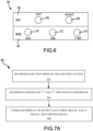
- Method 200 comprises determining, by a controller, an ejection mode of the ejection system (step 202) and determining, by the controller, a position of a first arm switch assembly of a first ejection seat and a position of a second arm switch assembly of a second ejection seat (step 204).
- Method 200 may further include commanding, by the controller, a display to output at least one of a fault-free signal, a fault signal, or a warning signal based on the ejection mode, the position of the first arm switch assembly, and the position of the second arm switch assembly.
- the position of the first arm switch assembly and the position of the second arm switch assembly may each be at least one of an armed position or a safe position.
- step 202 includes determining, by controller 122, an ejection mode of ejection system 100.
- Step 204 includes determining, by controller 122, a position of pilot arm switch assembly 132 of pilot ejection seat 104 and a position of co-pilot arm switch assembly 134 of co-pilot ejection seat 106.
- Step 206 includes commanding, by controller, display 160 to output at least one of a fault-free signal, a fault signal, or a warning signal based on the ejection mode, the position of pilot arm switch assembly 132, and the position of co-pilot arm switch assembly 134.
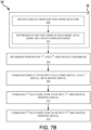
- step 202 may comprise receiving, by the controller, a signal from an ejection mode selector (step 208) and determining, by the controller, if the ejection mode is a solo mode, a dual mode, or a pilot command mode based on the signal from the ejection mode selector (step 210).
- step 208 may include receiving, by controller 122, signal 127 from ejection mode selector 126.
- Step 210 may include and determining, by controller 122, if the ejection mode is a solo mode, a dual mode, or a pilot command mode based on signal 127 from ejection mode selector 126.
- step 206 may include commanding, by controller 122, an indicator (e.g., solo mode indicator 170) of display 160 to output the fault-free signal in response to controller 122 determining the ejection mode is the solo mode, the pilot arm switch assembly 132 is in the armed position, and the co-pilot arm switch assembly 134 is in the safe position.
- an indicator e.g., solo mode indicator 170
- step 206 may include commanding, by controller 122, an indicator (e.g., solo mode indicator 170) of display 160 to output the fault signal in response to controller 122 determining the ejection mode is the solo mode and at least one of pilot arm switch assembly 132 is in the safe position or co-pilot arm switch assembly 134 is in the armed position.
- an indicator e.g., solo mode indicator 170
- step 206 may include commanding, by controller 122, an indicator (e.g., dual mode indicator 172) of display 160 to output the warning signal in response to controller 122 determining the ejection mode is the dual mode, the pilot arm switch assembly 132 is in the armed position, and co-pilot arm switch assembly 134 is in the armed position.
- step 206 may include commanding, by controller 122, an indicator (e.g., dual mode indicator 172) of display 160 to output the fault signal in response to controller 122 determining the ejection mode is the dual mode and at least one of pilot arm switch assembly 132 or co-pilot arm switch assembly 134 is in the safe position.
- step 206 may include commanding, by controller 122, an indicator (e.g., P_CMD mode indicator 174) of display 160 to output the warning signal in response to controller 122 determining the ejection mode is the pilot command mode, pilot arm switch assembly 132 is in the armed position, and co-pilot arm switch assembly 134 is in the armed position.
- step 206 may include commanding, by controller 122, an indicator (e.g., P_CMD mode indicator 174) of display 160 to output the fault signal in response to controller 122 determining the ejection mode is the pilot command mode and at least one of pilot arm switch assembly 132 or co-pilot arm switch assembly is in the safe position.
- an indicator e.g., P_CMD mode indicator 174
- method 200 may further comprise commanding, by the controller, a first seat indictor of the display to output a first arm switch position signal based on the position of the first arm switch assembly (step 212), and commanding, by the controller, a second seat indictor of the display to output a second arm switch position signal based on the position of the second arm switch assembly (step 214).
- step 212 may include commanding, by controller 122, pilot seat indicator 166 of display 160 to output an armed signal if controller 122 determines pilot arm switch assembly 132 is in the armed position or to output a safe signal if controller 122 determines pilot arm switch assembly 132 is in the safe position.
- step 214 may include commanding, by controller 122, co-pilot seat indicator 168 of display 160 to output the armed signal in response to controller 122 determining co-pilot arm switch assembly 134 is in the armed position or to output the safe signal in response to controller 122 determining co-pilot arm switch assembly 134 is in the safe position.
- references to "various embodiments”, “one embodiment”, “an embodiment”, “an example embodiment”, etc. indicate that the embodiment described may include a particular feature, structure, or characteristic, but every embodiment may not necessarily include the particular feature, structure, or characteristic. Moreover, such phrases are not necessarily referring to the same embodiment. Further, when a particular feature, structure, or characteristic is described in connection with an embodiment, it is submitted that it is within the knowledge of one skilled in the art to affect such feature, structure, or characteristic in connection with other embodiments whether or not explicitly described.
- the terms “comprises”, “comprising”, or any other variation thereof, are intended to cover a non-exclusive inclusion, such that a process, method, article, or apparatus that comprises a list of elements does not include only those elements but may include other elements not expressly listed or inherent to such process, method, article, or apparatus.
Landscapes
- Engineering & Computer Science (AREA)
- Aviation & Aerospace Engineering (AREA)
- Business, Economics & Management (AREA)
- Emergency Management (AREA)
- Transportation (AREA)
- Mechanical Engineering (AREA)
- Physics & Mathematics (AREA)
- General Physics & Mathematics (AREA)
- Automation & Control Theory (AREA)
- Mechanical Control Devices (AREA)
Claims (10)
- Doppelschalteraktivierungs- und Modusauswahlsystem (120) zum Überwachen einer Auswurfmodusauswahl eines Auswurfsystems, wobei das Doppelschalteraktivierungs- und Modusauswahlsystem folgendes umfasst:eine Steuerung (122);einen Auswurfmoduswähler (126), der mit der Steuerung in Kommunikation steht;eine erste Aktivierungsschalterbaugruppe (132), die mit der Steuerung in Kommunikation steht, wobei die erste Aktivierungsschalterbaugruppe so konfiguriert ist, dass sie zwischen einer sicheren Position und einer aktivierten Position wechselt;eine zweite Aktivierungsschalterbaugruppe (134), die mit der Steuerung in Kommunikation steht, wobei die zweite Aktivierungsschalterbaugruppe so konfiguriert ist, dass sie zwischen der sicheren Position und der aktivierten Position wechselt;eine Anzeige (160), die mit der Steuerung in Kommunikation steht; undein materielles, nicht transitorisches Medium (124), das dazu konfiguriert ist, mit der Steuerung zu kommunizieren, wobei auf dem materiellen, nicht transitorischen Medium Anweisungen gespeichert sind, die als Reaktion auf die Ausführung durch die Steuerung (122) die Steuerung dazu veranlassen, Vorgänge durchzuführen, die Folgendes umfassen:Bestimmen eines Auswurfmodus des Auswurfsystems durch die Steuerung (122) basierend auf einem von dem Auswurfmoduswähler empfangenen Signal;Bestimmen einer Position der ersten Aktivierungsschalterbaugruppe durch die Steuerung (122);Bestimmen einer Position der zweiten Aktivierungsschalterbaugruppe durch die Steuerung (122); undBefehlen des Bildschirms durch die Steuerung (122), mindestens eines von einem fehlerfreien Signal, einem Fehlersignal oder einem Warnsignal basierend auf dem Auswurfmodus, der Position der ersten Aktivierungsschalterbaugruppe und der Position der zweiten Aktivierungsschalterbaugruppe anzuzeigen.
- Doppelschalteraktivierungs- und Modusauswahlsystem nach Anspruch 1, wobei der Auswurfmodus mindestens einen von einem Solo-Modus, einem Dual-Modus oder einem Pilotbefehlsmodus umfasst.
- Doppelschalteraktivierungs- und Modusauswahlsystem nach Anspruch 2, wobei die Steuerung (122) so konfiguriert ist, dass sie einem ersten Indikator des Bildschirms befiehlt, das fehlerfreie Signal auszugeben, wenn die Steuerung bestimmt, dass der Auswurfmodus der Solo-Modus ist, die erste Aktivierungsschalterbaugruppe sich in der aktiven Position befindet und die zweite Aktivierungsschalterbaugruppe sich in der sicheren Position befindet; und
wobei die Steuerung (122) so konfiguriert ist, dass sie dem ersten Indikator des Bildschirms befiehlt, das Fehlersignal auszugeben, wenn die Steuerung bestimmt, dass der Auswurfmodus der Solo-Modus ist und mindestens einer der ersten Aktivierungsschalterbaugruppe sich in der sicheren Position oder der zweiten Aktivierungsschalterbaugruppe sich in der aktiven Position befindet. - Doppelschalteraktivierungs- und Modusauswahlsystem nach Anspruch 3, wobei die Steuerung (122) so konfiguriert ist, dass sie einem zweiten Indikator des Bildschirms befiehlt, das Warnsignal auszugeben, wenn die Steuerung bestimmt, dass der Auswurfmodus der Dual-Modus ist, die erste Aktivierungsschalterbaugruppe sich in der aktiven Position befindet und die zweite Aktivierungsschalterbaugruppe sich in der aktiven Position befindet; undwobei die Steuerung (122) so konfiguriert ist, dass sie dem zweiten Indikator des Bildschirms befiehlt, das Fehlersignal auszugeben, wenn die Steuerung bestimmt, dass der Auswurfmodus der Doppelmodus ist und mindestens eine der Aktivierungsschalterbaugruppe oder der zweiten Aktivierungsschalterbaugruppe sich in der sicheren Position befindet, und wobei die Steuerung vorzugsweise so konfiguriert ist, dass sie einem dritten Indikator des Bildschirms befiehlt, das Warnsignal auszugeben, wenn die Steuerung bestimmt, dass der Auswurfmodus der Pilotbefehlsmodus ist, die erste Aktivierungsschalterbaugruppe sich in der aktiven Position befindet und die zweite Aktivierungsschalterbaugruppe sich in der aktiven Position befindet; undwobei die Steuerung so konfiguriert ist, dass sie dem dritten Indikator des Bildschirms befiehlt, das Fehlersignal auszugeben, wenn die Steuerung bestimmt, dass der Auswurfmodus der Pilotbefehlsmodus ist und mindestens einer der ersten Aktivierungsschalterbaugruppe oder der zweiten Aktivierungsschalterbaugruppe sich in der sicheren Position befindet.
- Doppelschalteraktivierungs- und Modusauswahlsystem nach Anspruch 3, wobei die Steuerung (122) so konfiguriert ist, dass sie einem ersten Sitzindikator des Bildschirms befiehlt, ein Aktivierungssignal auszugeben, wenn die Steuerung bestimmt, dass sich die erste Aktivierungsschalterbaugruppe in der aktiven Position befindet; und
wobei die Steuerung (122) so konfiguriert ist, dass sie einem zweiten Sitzindikator des Bildschirms befiehlt, das Aktivierungssignal auszugeben, wenn die Steuerung bestimmt, dass sich die zweite Aktivierungsschalterbaugruppe in der aktiven Position befindet. - Doppelschalterschalteraktivierungs- und Modusauswahlsystem nach Anspruch 5, wobei die erste Aktivierungsschalterbaugruppe (132) einen Hebel und eine Schaltungsbaugruppe umfasst, wobei die Schaltungsbaugruppe so konfiguriert ist, dass sie ein Aktivierungsschalterpositionssignal an die Steuerung ausgibt; und
wobei Bestimmen der Position der ersten Aktivierungsschalterbaugruppe durch die Steuerung (122) umfasst:Empfangen des Positionssignals des Armschalters von der Schaltungsanordnung durch die Steuerung (122); undBestimmen, durch die Steuerung (122), ob sich die erste Aktivierungsschalterbaugruppe in der aktiven Position oder in der sicheren Position befindet, basierend auf dem Aktivierungsschalterpositionssignal; oderwobei die erste Aktivierungsschalterbaugruppe einen Hebel und einen Sensor umfasst; undwobei Bestimmen der Position der ersten Aktivierungsschalterbaugruppe durch die Steuerung (122) umfasst:Empfangen eines Signals von dem Sensor durch die Steuerung (122); undBestimmen, durch die Steuerung (122), ob sich die erste Aktivierungsschalterbaugruppe in der aktiven Position oder in der sicheren Position befindet, basierend auf dem Signal des Sensors. - Verfahren zur Überwachung einer Auswurfmodusauswahl für ein Schleudersystem, wobei das Verfahren folgendes umfasst:Bestimmen eines Auswurfmodus des Auswurfsystems durch eine Steuerung;Bestimmen einer Position einer ersten Aktivierungsschalterbaugruppe eines ersten Auswurfsitzes durch die Steuerung, wobei die Position der ersten Aktivierungsschalterbaugruppe mindestens eine aktive Position oder eine sichere Position ist;Bestimmen einer Position einer zweiten Aktivierungsschalterbaugruppe eines zweiten Auswurfsitzes durch die Steuerung, wobei die Position der zweiten Aktivierungsschalterbaugruppe mindestens eine aktive Position oder eine sichere Position ist; undBefehlen eines Bildschirms durch die Steuerung, mindestens eines von einem fehlerfreien Signal, einem Fehlersignal oder einem Warnsignal basierend auf dem Auswurfmodus, der Position der ersten Aktivierungsschalterbaugruppe und der Position der zweiten Aktivierungsschalterbaugruppe anzuzeigen.
- Verfahren nach Anspruch 7, wobei das Bestimmen des Auswurfmodus des Auswurfsystems durch die Steuerung Folgendes umfasst:Empfangen eines Signals von einem Auswurfmodus-Selektor durch die Steuerung; undBestimmen des Auswurfmodus durch die Steuerung basierend auf dem Signal, wobei der Auswurfmodus mindestens einen Solo-Modus, einen Dual-Modus oder einen Pilotbefehlsmodus umfasst, basierend auf dem Signal des Auswurfmodus-Selektors.
- Verfahren nach Anspruch 8, wobei das Befehlen des Bildschirms durch die Steuerung zur Ausgabe mindestens eines von dem fehlerfreien Signal, dem Fehlersignal oder dem Warnsignal mindestens eines von Folgendem umfasst:Befehlen eines Indikators des Bildschirms durch die Steuerung, das fehlerfreie Signal auszugeben, wenn die Steuerung bestimmt, dass der Auswurfmodus der Solo-Modus ist, die erste Aktivierungsschalterbaugruppe sich in der aktiven Position befindet und die zweite Aktivierungsschalterbaugruppe sich in der sicheren Position befindet; oderBefehlen des Indikators des Bildschirms durch die Steuerung, das Fehlersignal auszugeben, wenn die Steuerung bestimmt, dass der Auswurfmodus der Solo-Modus ist und mindestens eine der Aktivierungsschalterbaugruppen in der sicheren Position oder die zweite Aktivierungsschalterbaugruppe in der aktiven Position ist; oderwobei das Befehlen des Bildschirms durch die Steuerung zur Ausgabe mindestens eines von dem fehlerfreien Signal, dem Fehlersignal oder dem Warnsignal mindestens eines von Folgendem umfasst:Befehlen eines Indikators des Bildschirms durch die Steuerung, das Warnsignal auszugeben, wenn die Steuerung bestimmt, dass der Auswurfmodus der Dual-Modus ist, die erste Aktivierungsschalterbaugruppe sich in der aktiven Position befindet und die zweite Aktivierungsschalterbaugruppe sich in der aktiven Position befindet; oderBefehlen des Indikators des Bildschirms durch die Steuerung, das Fehlersignal auszugeben, wenn die Steuerung bestimmt, dass der Auswurfmodus der Dual-Modus ist und mindestens eine der Aktivierungsschalterbaugruppen oder die zweite Aktivierungsschalterbaugruppe in der sicheren Position ist.
- Verfahren nach Anspruch 8, wobei das Befehlen des Bildschirms durch die Steuerung zur Ausgabe mindestens eines von dem fehlerfreien Signal, dem Fehlersignal oder dem Warnsignal mindestens eines von Folgendem umfasst:Befehlen eines Indikators des Bildschirms durch die Steuerung, das Warnsignal auszugeben, wenn die Steuerung bestimmt, dass der Auswurfmodus der Pilotbefehlsmodus ist, die erste Aktivierungsschalterbaugruppe sich in der aktiven Position befindet und die zweite Aktivierungsschalterbaugruppe sich in der aktiven Position befindet; oderBefehlen des Indikators des Bildschirms durch die Steuerung, das Fehlersignal auszugeben, wenn die Steuerung bestimmt, dass der Auswurfmodus der Pilotbefehlsmodus ist und mindestens eine der Aktivierungsschalterbaugruppen oder die zweite Aktivierungsschalterbaugruppe in der sicheren Position ist, undvorzugsweise eines von Folgendem umfasst:Befehlen eines ersten Sitzindikators des Bildschirms durch die Steuerung, ein Aktivierungssignal auszugeben, wenn die Steuerung feststellt, dass die erste Aktivierungsschalterbaugruppe sich in der aktiven Position befindet;Befehlen des ersten Sitzindikators des Bildschirms durch die Steuerung, ein Sicherheitssignal auszugeben, wenn die Steuerung bestimmt, dass sich die erste Aktivierungsschalterbaugruppe in der sicheren Position befindet;Befehlen eines zweiten Sitzindikators des Bildschirms durch die Steuerung, das Aktivierungssignal auszugeben, wenn die Steuerung bestimmt, dass sich die zweite Aktivierungsschalterbaugruppe in der aktiven Position befindet; oderBefehlen des zweiten Sitzindikators des Bildschirms durch die Steuerung, das Sicherheitssignal auszugeben, wenn die Steuerung bestimmt, dass sich die zweite Aktivierungsschalterbaugruppe in der sicheren Position befindet.
Applications Claiming Priority (1)
| Application Number | Priority Date | Filing Date | Title |
|---|---|---|---|
| US17/152,434 US11655040B2 (en) | 2021-01-19 | 2021-01-19 | Dual function arm switch and mode select system for ejection systems |
Publications (2)
| Publication Number | Publication Date |
|---|---|
| EP4029782A1 EP4029782A1 (de) | 2022-07-20 |
| EP4029782B1 true EP4029782B1 (de) | 2024-08-07 |
Family
ID=79231060
Family Applications (1)
| Application Number | Title | Priority Date | Filing Date |
|---|---|---|---|
| EP22150225.5A Active EP4029782B1 (de) | 2021-01-19 | 2022-01-04 | Doppelfunktions aktivierungsschalter und modusauswahlsystem für auswurfsysteme |
Country Status (2)
| Country | Link |
|---|---|
| US (1) | US11655040B2 (de) |
| EP (1) | EP4029782B1 (de) |
Families Citing this family (3)
| Publication number | Priority date | Publication date | Assignee | Title |
|---|---|---|---|---|
| US11713127B2 (en) * | 2021-12-13 | 2023-08-01 | Ami Industries, Inc. | Multi-seat escape system and ejection seat sequencer |
| CN116811693A (zh) * | 2023-06-06 | 2023-09-29 | 奇瑞汽车股份有限公司 | 用于飞行汽车的弹射座椅及具有其的车辆 |
| CN117446183A (zh) * | 2023-12-11 | 2024-01-26 | 航宇救生装备有限公司 | 一种并列双座电子式指令弹射系统自适应控制方法 |
Citations (1)
| Publication number | Priority date | Publication date | Assignee | Title |
|---|---|---|---|---|
| EP3822168A1 (de) * | 2019-11-16 | 2021-05-19 | AMI Industries, Inc. | Robuste sequenziersysteme für schleudervorrichtung |
Family Cites Families (6)
| Publication number | Priority date | Publication date | Assignee | Title |
|---|---|---|---|---|
| US3633852A (en) * | 1970-03-31 | 1972-01-11 | Fairchild Hiller Corp | Aircraft seat ejection safety system |
| US4290568A (en) * | 1979-11-09 | 1981-09-22 | The United States Of America As Represented By The Secretary Of The Air Force | Aircraft ejection seat safetying device |
| US4673147A (en) * | 1985-02-21 | 1987-06-16 | Rockwell International Corporation | Programmable ejection seat system |
| US4911382A (en) * | 1989-01-17 | 1990-03-27 | Grumman Aerospace Corporation | Safe electro ballistic escape sequencing system |
| CN201355433Y (zh) | 2008-12-30 | 2009-12-02 | 武汉航空仪表有限责任公司 | 一种飞机座椅弹射开锁控制电路 |
| US10384788B2 (en) * | 2016-04-18 | 2019-08-20 | Goodrich Corporation | Multiple aircraft seat ejection mode selector |
-
2021
- 2021-01-19 US US17/152,434 patent/US11655040B2/en active Active
-
2022
- 2022-01-04 EP EP22150225.5A patent/EP4029782B1/de active Active
Patent Citations (1)
| Publication number | Priority date | Publication date | Assignee | Title |
|---|---|---|---|---|
| EP3822168A1 (de) * | 2019-11-16 | 2021-05-19 | AMI Industries, Inc. | Robuste sequenziersysteme für schleudervorrichtung |
Also Published As
| Publication number | Publication date |
|---|---|
| US11655040B2 (en) | 2023-05-23 |
| US20220227496A1 (en) | 2022-07-21 |
| EP4029782A1 (de) | 2022-07-20 |
Similar Documents
| Publication | Publication Date | Title |
|---|---|---|
| EP4029782B1 (de) | Doppelfunktions aktivierungsschalter und modusauswahlsystem für auswurfsysteme | |
| EP2108585B1 (de) | System und Methode zur Vorbeugung einer unbeabsichtigten Notrutschenentfaltung für ein Flugzeug | |
| US8473189B2 (en) | Helicopter having collision avoidance apparatus | |
| US9870691B2 (en) | Apparatus for operating a door of an aircraft, an aircraft having such an apparatus and method for operating a door of an aircraft | |
| US10988251B2 (en) | On-board emergency response system for a vehicle | |
| US20090319104A1 (en) | System for guiding and piloting an aircraft in case of inability of the pilots | |
| US12122522B2 (en) | Flying object operation device, malfunction prevention method for flying object operation device, flying object thrust generation device, parachute or paraglider deploying device, and airbag device | |
| US9004400B2 (en) | Method of controlling a buoyancy system for an aircraft, a buoyancy system implementing said method, and an aircraft | |
| WO2010002437A2 (en) | Smart recovery system | |
| EP2023507B1 (de) | Automatische Abwärtsmitteilungen in Flug-Notfallsituationen | |
| EP3287366A1 (de) | Flugzeug mit einem notschwimmersystem | |
| US6633239B2 (en) | Cargo door electrical control and warning indication system and method of use | |
| EP2780231B1 (de) | Überwachungsvorrichtung und verfahren zur überwachung eines bewegungsprofils eines benutzers in der region eines betätigungselements eines luft-oder raumfahrzeuges | |
| US11608183B2 (en) | Automatic ejection time delay system | |
| EP2982601B1 (de) | Sicherheitssystem für flugzeuge | |
| US12162610B2 (en) | Readiness indicator light system for evacuation slide | |
| US7271713B2 (en) | Digital automatic escape system | |
| US8044825B2 (en) | Aircraft security | |
| GB2614953A (en) | Multi-seat escape system and ejection seat sequencer | |
| US12134479B2 (en) | Readiness indicator light system having projection light for evacuation slide | |
| EP4270341B1 (de) | Intelligentes evakuierungsleitsystem | |
| EP1980489A2 (de) | Flugzeugsicherheit | |
| EP4190697B1 (de) | Bereitschaftsanzeigelichtsystem mit projektionslicht für notrutsche | |
| US20230227167A1 (en) | Parachute and inflatable assembly for air taxi | |
| US12448132B2 (en) | Slide pack growth detection method of evacuation slides or slide/rafts |
Legal Events
| Date | Code | Title | Description |
|---|---|---|---|
| PUAI | Public reference made under article 153(3) epc to a published international application that has entered the european phase |
Free format text: ORIGINAL CODE: 0009012 |
|
| STAA | Information on the status of an ep patent application or granted ep patent |
Free format text: STATUS: THE APPLICATION HAS BEEN PUBLISHED |
|
| AK | Designated contracting states |
Kind code of ref document: A1 Designated state(s): AL AT BE BG CH CY CZ DE DK EE ES FI FR GB GR HR HU IE IS IT LI LT LU LV MC MK MT NL NO PL PT RO RS SE SI SK SM TR |
|
| STAA | Information on the status of an ep patent application or granted ep patent |
Free format text: STATUS: REQUEST FOR EXAMINATION WAS MADE |
|
| 17P | Request for examination filed |
Effective date: 20230110 |
|
| RBV | Designated contracting states (corrected) |
Designated state(s): AL AT BE BG CH CY CZ DE DK EE ES FI FR GB GR HR HU IE IS IT LI LT LU LV MC MK MT NL NO PL PT RO RS SE SI SK SM TR |
|
| P01 | Opt-out of the competence of the unified patent court (upc) registered |
Effective date: 20230922 |
|
| GRAP | Despatch of communication of intention to grant a patent |
Free format text: ORIGINAL CODE: EPIDOSNIGR1 |
|
| STAA | Information on the status of an ep patent application or granted ep patent |
Free format text: STATUS: GRANT OF PATENT IS INTENDED |
|
| RIC1 | Information provided on ipc code assigned before grant |
Ipc: G05B 19/042 20060101ALN20240220BHEP Ipc: B64D 11/06 20060101ALN20240220BHEP Ipc: B60N 2/427 20060101ALN20240220BHEP Ipc: B64D 25/10 20060101AFI20240220BHEP |
|
| RIC1 | Information provided on ipc code assigned before grant |
Ipc: G05B 19/042 20060101ALN20240227BHEP Ipc: B64D 11/06 20060101ALN20240227BHEP Ipc: B60N 2/427 20060101ALN20240227BHEP Ipc: B64D 25/10 20060101AFI20240227BHEP |
|
| INTG | Intention to grant announced |
Effective date: 20240313 |
|
| GRAS | Grant fee paid |
Free format text: ORIGINAL CODE: EPIDOSNIGR3 |
|
| GRAA | (expected) grant |
Free format text: ORIGINAL CODE: 0009210 |
|
| STAA | Information on the status of an ep patent application or granted ep patent |
Free format text: STATUS: THE PATENT HAS BEEN GRANTED |
|
| AK | Designated contracting states |
Kind code of ref document: B1 Designated state(s): AL AT BE BG CH CY CZ DE DK EE ES FI FR GB GR HR HU IE IS IT LI LT LU LV MC MK MT NL NO PL PT RO RS SE SI SK SM TR |
|
| REG | Reference to a national code |
Ref country code: GB Ref legal event code: FG4D |
|
| REG | Reference to a national code |
Ref country code: CH Ref legal event code: EP |
|
| REG | Reference to a national code |
Ref country code: IE Ref legal event code: FG4D |
|
| REG | Reference to a national code |
Ref country code: DE Ref legal event code: R096 Ref document number: 602022005031 Country of ref document: DE |
|
| REG | Reference to a national code |
Ref country code: LT Ref legal event code: MG9D |
|
| REG | Reference to a national code |
Ref country code: NL Ref legal event code: MP Effective date: 20240807 |
|
| PG25 | Lapsed in a contracting state [announced via postgrant information from national office to epo] |
Ref country code: NO Free format text: LAPSE BECAUSE OF FAILURE TO SUBMIT A TRANSLATION OF THE DESCRIPTION OR TO PAY THE FEE WITHIN THE PRESCRIBED TIME-LIMIT Effective date: 20241107 |
|
| REG | Reference to a national code |
Ref country code: AT Ref legal event code: MK05 Ref document number: 1710664 Country of ref document: AT Kind code of ref document: T Effective date: 20240807 |
|
| PG25 | Lapsed in a contracting state [announced via postgrant information from national office to epo] |
Ref country code: FI Free format text: LAPSE BECAUSE OF FAILURE TO SUBMIT A TRANSLATION OF THE DESCRIPTION OR TO PAY THE FEE WITHIN THE PRESCRIBED TIME-LIMIT Effective date: 20240807 Ref country code: NL Free format text: LAPSE BECAUSE OF FAILURE TO SUBMIT A TRANSLATION OF THE DESCRIPTION OR TO PAY THE FEE WITHIN THE PRESCRIBED TIME-LIMIT Effective date: 20240807 Ref country code: PT Free format text: LAPSE BECAUSE OF FAILURE TO SUBMIT A TRANSLATION OF THE DESCRIPTION OR TO PAY THE FEE WITHIN THE PRESCRIBED TIME-LIMIT Effective date: 20241209 Ref country code: PL Free format text: LAPSE BECAUSE OF FAILURE TO SUBMIT A TRANSLATION OF THE DESCRIPTION OR TO PAY THE FEE WITHIN THE PRESCRIBED TIME-LIMIT Effective date: 20240807 Ref country code: GR Free format text: LAPSE BECAUSE OF FAILURE TO SUBMIT A TRANSLATION OF THE DESCRIPTION OR TO PAY THE FEE WITHIN THE PRESCRIBED TIME-LIMIT Effective date: 20241108 |
|
| PG25 | Lapsed in a contracting state [announced via postgrant information from national office to epo] |
Ref country code: BG Free format text: LAPSE BECAUSE OF FAILURE TO SUBMIT A TRANSLATION OF THE DESCRIPTION OR TO PAY THE FEE WITHIN THE PRESCRIBED TIME-LIMIT Effective date: 20240807 |
|
| PG25 | Lapsed in a contracting state [announced via postgrant information from national office to epo] |
Ref country code: LV Free format text: LAPSE BECAUSE OF FAILURE TO SUBMIT A TRANSLATION OF THE DESCRIPTION OR TO PAY THE FEE WITHIN THE PRESCRIBED TIME-LIMIT Effective date: 20240807 |
|
| PG25 | Lapsed in a contracting state [announced via postgrant information from national office to epo] |
Ref country code: IS Free format text: LAPSE BECAUSE OF FAILURE TO SUBMIT A TRANSLATION OF THE DESCRIPTION OR TO PAY THE FEE WITHIN THE PRESCRIBED TIME-LIMIT Effective date: 20241207 Ref country code: AT Free format text: LAPSE BECAUSE OF FAILURE TO SUBMIT A TRANSLATION OF THE DESCRIPTION OR TO PAY THE FEE WITHIN THE PRESCRIBED TIME-LIMIT Effective date: 20240807 |
|
| PG25 | Lapsed in a contracting state [announced via postgrant information from national office to epo] |
Ref country code: HR Free format text: LAPSE BECAUSE OF FAILURE TO SUBMIT A TRANSLATION OF THE DESCRIPTION OR TO PAY THE FEE WITHIN THE PRESCRIBED TIME-LIMIT Effective date: 20240807 |
|
| PG25 | Lapsed in a contracting state [announced via postgrant information from national office to epo] |
Ref country code: ES Free format text: LAPSE BECAUSE OF FAILURE TO SUBMIT A TRANSLATION OF THE DESCRIPTION OR TO PAY THE FEE WITHIN THE PRESCRIBED TIME-LIMIT Effective date: 20240807 Ref country code: RS Free format text: LAPSE BECAUSE OF FAILURE TO SUBMIT A TRANSLATION OF THE DESCRIPTION OR TO PAY THE FEE WITHIN THE PRESCRIBED TIME-LIMIT Effective date: 20241107 |
|
| PG25 | Lapsed in a contracting state [announced via postgrant information from national office to epo] |
Ref country code: RS Free format text: LAPSE BECAUSE OF FAILURE TO SUBMIT A TRANSLATION OF THE DESCRIPTION OR TO PAY THE FEE WITHIN THE PRESCRIBED TIME-LIMIT Effective date: 20241107 Ref country code: PT Free format text: LAPSE BECAUSE OF FAILURE TO SUBMIT A TRANSLATION OF THE DESCRIPTION OR TO PAY THE FEE WITHIN THE PRESCRIBED TIME-LIMIT Effective date: 20241209 Ref country code: PL Free format text: LAPSE BECAUSE OF FAILURE TO SUBMIT A TRANSLATION OF THE DESCRIPTION OR TO PAY THE FEE WITHIN THE PRESCRIBED TIME-LIMIT Effective date: 20240807 Ref country code: NO Free format text: LAPSE BECAUSE OF FAILURE TO SUBMIT A TRANSLATION OF THE DESCRIPTION OR TO PAY THE FEE WITHIN THE PRESCRIBED TIME-LIMIT Effective date: 20241107 Ref country code: NL Free format text: LAPSE BECAUSE OF FAILURE TO SUBMIT A TRANSLATION OF THE DESCRIPTION OR TO PAY THE FEE WITHIN THE PRESCRIBED TIME-LIMIT Effective date: 20240807 Ref country code: LV Free format text: LAPSE BECAUSE OF FAILURE TO SUBMIT A TRANSLATION OF THE DESCRIPTION OR TO PAY THE FEE WITHIN THE PRESCRIBED TIME-LIMIT Effective date: 20240807 Ref country code: IS Free format text: LAPSE BECAUSE OF FAILURE TO SUBMIT A TRANSLATION OF THE DESCRIPTION OR TO PAY THE FEE WITHIN THE PRESCRIBED TIME-LIMIT Effective date: 20241207 Ref country code: HR Free format text: LAPSE BECAUSE OF FAILURE TO SUBMIT A TRANSLATION OF THE DESCRIPTION OR TO PAY THE FEE WITHIN THE PRESCRIBED TIME-LIMIT Effective date: 20240807 Ref country code: GR Free format text: LAPSE BECAUSE OF FAILURE TO SUBMIT A TRANSLATION OF THE DESCRIPTION OR TO PAY THE FEE WITHIN THE PRESCRIBED TIME-LIMIT Effective date: 20241108 Ref country code: FI Free format text: LAPSE BECAUSE OF FAILURE TO SUBMIT A TRANSLATION OF THE DESCRIPTION OR TO PAY THE FEE WITHIN THE PRESCRIBED TIME-LIMIT Effective date: 20240807 Ref country code: ES Free format text: LAPSE BECAUSE OF FAILURE TO SUBMIT A TRANSLATION OF THE DESCRIPTION OR TO PAY THE FEE WITHIN THE PRESCRIBED TIME-LIMIT Effective date: 20240807 Ref country code: BG Free format text: LAPSE BECAUSE OF FAILURE TO SUBMIT A TRANSLATION OF THE DESCRIPTION OR TO PAY THE FEE WITHIN THE PRESCRIBED TIME-LIMIT Effective date: 20240807 Ref country code: AT Free format text: LAPSE BECAUSE OF FAILURE TO SUBMIT A TRANSLATION OF THE DESCRIPTION OR TO PAY THE FEE WITHIN THE PRESCRIBED TIME-LIMIT Effective date: 20240807 |
|
| PG25 | Lapsed in a contracting state [announced via postgrant information from national office to epo] |
Ref country code: SM Free format text: LAPSE BECAUSE OF FAILURE TO SUBMIT A TRANSLATION OF THE DESCRIPTION OR TO PAY THE FEE WITHIN THE PRESCRIBED TIME-LIMIT Effective date: 20240807 Ref country code: DK Free format text: LAPSE BECAUSE OF FAILURE TO SUBMIT A TRANSLATION OF THE DESCRIPTION OR TO PAY THE FEE WITHIN THE PRESCRIBED TIME-LIMIT Effective date: 20240807 |
|
| PG25 | Lapsed in a contracting state [announced via postgrant information from national office to epo] |
Ref country code: EE Free format text: LAPSE BECAUSE OF FAILURE TO SUBMIT A TRANSLATION OF THE DESCRIPTION OR TO PAY THE FEE WITHIN THE PRESCRIBED TIME-LIMIT Effective date: 20240807 |
|
| PG25 | Lapsed in a contracting state [announced via postgrant information from national office to epo] |
Ref country code: CZ Free format text: LAPSE BECAUSE OF FAILURE TO SUBMIT A TRANSLATION OF THE DESCRIPTION OR TO PAY THE FEE WITHIN THE PRESCRIBED TIME-LIMIT Effective date: 20240807 |
|
| PG25 | Lapsed in a contracting state [announced via postgrant information from national office to epo] |
Ref country code: SK Free format text: LAPSE BECAUSE OF FAILURE TO SUBMIT A TRANSLATION OF THE DESCRIPTION OR TO PAY THE FEE WITHIN THE PRESCRIBED TIME-LIMIT Effective date: 20240807 |
|
| REG | Reference to a national code |
Ref country code: DE Ref legal event code: R097 Ref document number: 602022005031 Country of ref document: DE |
|
| PLBE | No opposition filed within time limit |
Free format text: ORIGINAL CODE: 0009261 |
|
| STAA | Information on the status of an ep patent application or granted ep patent |
Free format text: STATUS: NO OPPOSITION FILED WITHIN TIME LIMIT |
|
| 26N | No opposition filed |
Effective date: 20250508 |
|
| REG | Reference to a national code |
Ref country code: CH Ref legal event code: PL |
|
| PG25 | Lapsed in a contracting state [announced via postgrant information from national office to epo] |
Ref country code: SE Free format text: LAPSE BECAUSE OF FAILURE TO SUBMIT A TRANSLATION OF THE DESCRIPTION OR TO PAY THE FEE WITHIN THE PRESCRIBED TIME-LIMIT Effective date: 20240807 |
|
| PG25 | Lapsed in a contracting state [announced via postgrant information from national office to epo] |
Ref country code: LU Free format text: LAPSE BECAUSE OF NON-PAYMENT OF DUE FEES Effective date: 20250104 Ref country code: MC Free format text: LAPSE BECAUSE OF FAILURE TO SUBMIT A TRANSLATION OF THE DESCRIPTION OR TO PAY THE FEE WITHIN THE PRESCRIBED TIME-LIMIT Effective date: 20240807 |
|
| PG25 | Lapsed in a contracting state [announced via postgrant information from national office to epo] |
Ref country code: BE Free format text: LAPSE BECAUSE OF NON-PAYMENT OF DUE FEES Effective date: 20250131 |
|
| PG25 | Lapsed in a contracting state [announced via postgrant information from national office to epo] |
Ref country code: CH Free format text: LAPSE BECAUSE OF NON-PAYMENT OF DUE FEES Effective date: 20250131 |
|
| REG | Reference to a national code |
Ref country code: BE Ref legal event code: MM Effective date: 20250131 |
|
| PGFP | Annual fee paid to national office [announced via postgrant information from national office to epo] |
Ref country code: GB Payment date: 20251220 Year of fee payment: 5 |
|
| PGFP | Annual fee paid to national office [announced via postgrant information from national office to epo] |
Ref country code: FR Payment date: 20251218 Year of fee payment: 5 |
|
| PG25 | Lapsed in a contracting state [announced via postgrant information from national office to epo] |
Ref country code: IE Free format text: LAPSE BECAUSE OF NON-PAYMENT OF DUE FEES Effective date: 20250104 |
|
| PG25 | Lapsed in a contracting state [announced via postgrant information from national office to epo] |
Ref country code: IT Free format text: LAPSE BECAUSE OF FAILURE TO SUBMIT A TRANSLATION OF THE DESCRIPTION OR TO PAY THE FEE WITHIN THE PRESCRIBED TIME-LIMIT Effective date: 20240807 |
|
| PGFP | Annual fee paid to national office [announced via postgrant information from national office to epo] |
Ref country code: DE Payment date: 20251217 Year of fee payment: 5 |
|
| PG25 | Lapsed in a contracting state [announced via postgrant information from national office to epo] |
Ref country code: RO Free format text: LAPSE BECAUSE OF FAILURE TO SUBMIT A TRANSLATION OF THE DESCRIPTION OR TO PAY THE FEE WITHIN THE PRESCRIBED TIME-LIMIT Effective date: 20240807 |