EP4029739A1 - Safety apparatus for indicating the usage state of a seat belt - Google Patents
Safety apparatus for indicating the usage state of a seat belt Download PDFInfo
- Publication number
- EP4029739A1 EP4029739A1 EP21215512.1A EP21215512A EP4029739A1 EP 4029739 A1 EP4029739 A1 EP 4029739A1 EP 21215512 A EP21215512 A EP 21215512A EP 4029739 A1 EP4029739 A1 EP 4029739A1
- Authority
- EP
- European Patent Office
- Prior art keywords
- indicator
- strap
- seat
- safety apparatus
- buckle
- Prior art date
- Legal status (The legal status is an assumption and is not a legal conclusion. Google has not performed a legal analysis and makes no representation as to the accuracy of the status listed.)
- Granted
Links
Images

Classifications
-
- B—PERFORMING OPERATIONS; TRANSPORTING
- B60—VEHICLES IN GENERAL
- B60R—VEHICLES, VEHICLE FITTINGS, OR VEHICLE PARTS, NOT OTHERWISE PROVIDED FOR
- B60R22/00—Safety belts or body harnesses in vehicles
- B60R22/48—Control systems, alarms, or interlock systems, for the correct application of the belt or harness
-
- B—PERFORMING OPERATIONS; TRANSPORTING
- B60—VEHICLES IN GENERAL
- B60R—VEHICLES, VEHICLE FITTINGS, OR VEHICLE PARTS, NOT OTHERWISE PROVIDED FOR
- B60R22/00—Safety belts or body harnesses in vehicles
- B60R22/48—Control systems, alarms, or interlock systems, for the correct application of the belt or harness
- B60R2022/4808—Sensing means arrangements therefor
- B60R2022/4816—Sensing means arrangements therefor for sensing locking of buckle
-
- B—PERFORMING OPERATIONS; TRANSPORTING
- B60—VEHICLES IN GENERAL
- B60R—VEHICLES, VEHICLE FITTINGS, OR VEHICLE PARTS, NOT OTHERWISE PROVIDED FOR
- B60R22/00—Safety belts or body harnesses in vehicles
- B60R22/48—Control systems, alarms, or interlock systems, for the correct application of the belt or harness
- B60R2022/4808—Sensing means arrangements therefor
- B60R2022/4825—Sensing means arrangements therefor for sensing amount of belt winded on retractor
-
- B—PERFORMING OPERATIONS; TRANSPORTING
- B60—VEHICLES IN GENERAL
- B60R—VEHICLES, VEHICLE FITTINGS, OR VEHICLE PARTS, NOT OTHERWISE PROVIDED FOR
- B60R22/00—Safety belts or body harnesses in vehicles
- B60R22/48—Control systems, alarms, or interlock systems, for the correct application of the belt or harness
- B60R2022/4866—Displaying or indicating arrangements thereof
-
- B—PERFORMING OPERATIONS; TRANSPORTING
- B60—VEHICLES IN GENERAL
- B60R—VEHICLES, VEHICLE FITTINGS, OR VEHICLE PARTS, NOT OTHERWISE PROVIDED FOR
- B60R22/00—Safety belts or body harnesses in vehicles
- B60R22/34—Belt retractors, e.g. reels
Definitions
- the present disclosure relates to a safety apparatus for indicating the usage state of a seat belt.
- the present disclosure is particularly relevant to vehicle seat belt safety systems.
- Modern vehicles include ever increasing numbers of safety devices and systems, motivated not only by regulatory pressures but also consumer demand for improved road safety.
- One common feature is to provide a seat belt reminder or safety warning system for ensuring that occupants of a vehicle have buckled their seat belts. Initially, this system was provided only in respect of the first row of seats of a vehicle, and in some countries this feature has become a regulatory requirement for all new vehicles.
- both regulatory trends and consumer expectations are directed toward increased safety compliance, there is a growing demand to provide seat belt reminder systems which cover every seat in a vehicle. For example, parents often wish to be alerted if a child in a passenger seat has unbuckled their belt.
- Conventional seat belt reminder systems are normally based on a combination of a PODS (Pressure Occupant Detection System) and a lock switch system.
- the PODS is fitted into the vehicle seat base and is used to detect an occupant by detecting their weight on the seat.
- the lock switch system is fitted into the seat belt buckle and confirms once the seat belt tongue has been locked into place. These systems then feed a safety controller to issue a reminder if a seat is occupied but the seat belt is unbuckled.
- PODS and lock switch systems require an electrical harness to be connected to every vehicle seat that is to be covered by the system. Although this is manageable for the front row seats, it becomes much more challenging when the system is to be extended to cover the second, third, or further rows of seats in larger vehicles. In this situation, additional wire harness cabling and connection terminals are needed to connect the components, which adds considerably to the expense and complexity of the system. However, the issue becomes even more complex in vehicles which have reconfigurable seats, such as in people carriers and larger sports utility vehicles. For example, some vehicles allow the second or later row seats to be individually moved forward or back, or flipped around to face the opposite direction, or even removed entirely. To accommodate this functionality, whilst also providing a conventional seat belt reminder system, would require connector terminals for the PODS and lock switch sensors to be provided on the vehicle floor for every possible seat configuration. This is typically not viable for cost reasons.
- a limitation of camera-based systems is that they require the seat belt and the buckle to be visible to the camera.
- these parts are prone to being covered by the nature of their operation. For example, jackets, blankets and other objects will often be on an occupant's lap or thrown on adjacent seats, where they may cover part or all of the seat belt or the buckle. Obstructing the camera's field of view in this way makes it extremely difficult for the neural network to interpret the image data consistently. As such, the functionality of the system may be compromised.
- camera-based systems are often used in conjunction with PODS and/or lock switch sensors to improve overall reliability. However, this only leads to even greater cost and complexity.
- a further drawback is that, in vehicles which do have reconfigurable seats, it is relatively complex to hardcode or train the neural network to be able to operate effectively in all possible seating combinations. Again, this leads to increased cost and processing overheads.
- a further complexity relates to a behaviour pattern of some occupants to attempt to circumvent seat belt safety systems.
- an occupant may connect the tongue directly into the buckle before they sit down, so that the strap is deployed behind their back once they are seated.
- tamper devices are available for locking into the buckle to replicate the tongue being locked into place.
- Conventional PODS and lock switch systems cannot detect this type of behaviour, and although camera-based systems should provide some detection, this is limited by requiring the seat belt strap to be visible. For safety regulators, this potential for misuse presents a problem because safety systems can only be deemed effective to the extent that they are used properly and consistently.
- the present disclosure concerns a vehicle camera assembly and method of assembling a vehicle camera assembly.
- a safety apparatus for indicating the usage state of a seat belt having a strap spooled from a retractor and being lockable to a buckle by a tongue
- the apparatus including: an indicator unit for mounting to an upper region of a seat; a lock indicator provided on the indicator unit and being operably connectable to the buckle for indicating a state when the tongue has been locked into the buckle; and a strap indicator for indicating a state when a spooled length of the strap exceeds a threshold corresponding to a predetermined minimum length of strap needed to secure a body with the seat belt; and wherein the lock indicator and the strap indicator are detectable by a camera.
- an indication of the locking and belt strap status of a seat may be determined by processing images from the camera. By combining this with seat occupancy information, it may therefore be determined whether the seat belt is being used correctly, and provide for an alert to be issued in circumstances where it isn't.
- the indicator unit By mounting the indicator unit to an upper region of the seat, the indicators may be positioned above an occupant's shoulders, thereby mitigating the risk of obstruction by clothing or other objects.
- greater flexibility is achieved in terms of allowing seats to be reconfigured, whilst minimising the costs and complexity associated with additional wire harnesses.
- the strap indicator is provided on the indicator unit. In this way, a single indicator unit may be provided, thereby narrowing the field of view required for image analysis to determine the status of the indicators.
- the indicator unit includes a mounting for securing the indicator unit to one of a shoulder of the seat and a headrest.
- the strap indicator includes a strap indicator element mechanically movable from a negative position to a positive position for indicating the spooled length of strap has exceeded the threshold. In this way, the indicator does not require a power source or connection to the vehicle's electronic systems.
- movement of the strap indicator element to a positive position exposes a visible marker for detection by the camera.
- the strap indicator element is connected to the retractor by a spool indicator mechanism for moving the strap indicator element proportionally as the strap is spooled from the retractor. In this way, the strap indicator element may be used to gauge the length of strap drawn from the retractor.
- the lock indicator includes a lock indicator element mechanically movable from a negative position to a positive position for indicating the tongue has been locked into the buckle.
- the lock indicator element is operably connectable to the buckle by a mechanical linkage for moving the lock indicator element into the positive position when the tongue locks into the buckle. In this way, the indicator does not require a power source or connection to the vehicle's electronic systems.
- the mechanical linkage includes a seat section for securing within the interior the seat between the buckle and the indicator unit. In this way, the mechanical connection may be built into the seat unit itself.
- the seat section includes a Bowden cable. In this way, an inexpensive mechanism is provided for actuating the lock indicator.
- movement of the lock indicator element to a positive position exposes a visible marker for detection by the camera.
- the safety apparatus further includes a locator marking provided on the indicator unit for detection by the camera.
- a locator marking provided on the indicator unit for detection by the camera.
- the locator marking includes one or more orientation features for determining seat orientation based on an image detected by the camera. In this way, the orientation of the indicator unit, and hence the seat itself, may be more easily determined through image recognition based on the detected orientation of the markings.
- the safety apparatus further includes: a camera unit for detecting an image of the lock indicator and the strap indicator; and a processor for processing the image to identify the state of the lock indicator and the strap indicator.
- the apparatus may be provided as a seat belt safety system.
- the processor further includes an occupancy detector for detecting an occupant in the seat.
- FIG. 1 shows a vehicle seat 1 incorporating the seat belt safety apparatus according to an illustrative embodiment.
- the seat includes a base 101, a back part 102, and a headrest 104 mounted to the shoulder region 103 of the back part 102.
- the shoulder region 103 and the headrest 104 form an upper region of the seat 1.
- the seat belt includes a strap 3, which is fixed at one end to a side of the seat base 101 by a strap fixing 31 and is spooled onto a retractor 51 housed within housing unit 5 mounted to the seat's shoulder region 103 at the other end.
- a tongue 4 is slidably coupled to the strap 3 between the strap fixing 31 and the retractor 51.
- a buckle 2 for receiving and locking the tongue 4 is provided on the seat base, at the side opposite to the strap fixing 31.
- the housing unit 5 In addition to housing the retractor 51, the housing unit 5 also includes a display face 52 on an upper surface for displaying a number of indicators, as is described in further detail below. As such, the housing unit 5 provides an indicator unit for indicating seat belt status information.
- the seat belt safety apparatus further includes a camera 7 and a processor 6 which processes images from the camera 7.
- the camera 7 and processor 6 are integrated into the vehicle, with the processor 6 being part of the vehicle's embedded safety control systems.
- the camera 7 is mounted to the ceiling of the vehicle's interior and is directed such that the display face 52 of the housing unit 5 is within its field of view.
- the indicators provided on the display face 52 are detectable by the camera.
- the indicators may be visible to the camera in the visible light spectrum and/or, for instance, in the infrared spectrum.
- embodiments may include an infrared emitter within the camera 7 assembly, with the indicators provided as an infrared reflective surface. The use of infrared may allow the indicators to be provided without compromising the aesthetics of the vehicle interior.
- the processor 6 processes images from the camera 7 to identify the indicators provided on the display face 52 of the housing unit 5.
- the processor 6 includes a neural network for this image processing.
- the processor 6 may also receive feeds from a number of further cameras or other sensors for interpreting other safety input information.
- the processor 6 is further used to implement a camera-based occupancy detection system. For this, the processor 6 receives a camera input and uses image recognition to identify when people are seated in each of the seats.
- FIG. 2 shows a partially exposed interior front view of the back part 102 of the seat 1.
- a lock indicator linkage 8 is provided in the seat interior for mechanically linking the locking mechanism in the buckle 2 to a lock indicator in the housing unit 5.
- the lock indicator linkage 8 is provided as a Bowden cable mechanism, wherein a flexible inner actuator cable is used to transmit movements associated with the locking and unlocking of the buckle mechanism through a hollow outer cable.
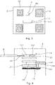
- Figures 3 and 4 respectively show the top and bottom sides of the display face 52 of the housing unit 5.
- the belt strap 3 is retracted and the tongue 4 is unbuckled.
- the exposed top side of the display face 52 includes the lock indicator 9, a strap indicator 11, and a plurality of locator markers 10.
- the lock indicator 9 includes an aperture 91 provided in the display face 52, through which a lock indicator element 13 is exposed.
- the lock indicator element 13 On the bottom side of the display face, as shown in Figure 4 , the lock indicator element 13 is slidably received within a track 12 and is connected at one end to the actuator cable 18 of the lock indicator linkage 8.
- the lock indicator element 13 includes a darkened section 132 for indicating the buckle is locked and a white section 131 for indicating the buckle is unlocked. Actuation of the buckle locking mechanism causes the actuator cable 18 to move the lock indicator element 13 along the track 12 from a first position where the white section 131 is exposed through the aperture 91, to a second position where the darkened section 132 is exposed.
- the belt lock indicator 9 provides a visual indicator when the buckle is locked in that the aperture 91 on the display face 52 shows the dark section 132.
- the strap indicator 11 includes an elongated aperture 111 in the display face 52, thorough which an strap indicator element 14 is exposed.
- the strap indicator element 14 is slidably received within a track 17.
- the strap indicator element 14 is coupled to the seat belt retractor 51 such that it is moved back and forth along the track 17 in response to the strap 3 being spooled into and out from the retractor 51.
- this spool indicator mechanism includes a lead screw 16 which is coupled to a lead screw nut connector 15 attached to the strap indicator element 14.
- a gear arrangement (not shown) causes rotation of the lead screw 16, which is translated to a linear movement of the lead screw nut connector 15 and, in turn, movement of the strap indicator element 14.
- the strap indicator element 14 is moved proportionally with the length of strap 3 spooled out from the retractor 51.
- the strap indicator element 14 further includes a white section 141 and a darkened section 142, with the darkened section 142 marking the point at which a minimum threshold length of strap 3 has been spooled from the retractor 51.
- the predetermined threshold is set for indicating when a sufficient length of strap 3 has been dispensed for securing around a body.
- the strap indicator element 14 is moved along the track 17 from a first position where the white section 141 is exposed through the strap indicator's aperture 111, to a second position where the darkened section 142 is exposed. As the strap 3 continues to feed out from the retractor 51, a larger proportion of the darkened section 142 is visible through the aperture 111.
- the size of the exposed darkened section 142 thereby provides a gauge for indicating not only that the threshold has been reached, but also the length of strap 3 dispensed.
- This length indicator may be interpreted by the processor 6 to provide data on the size of the occupant and therefore may be used to determine how the seatbelt is being used. For example, if the determined length of strap 3 is near to a maximum extension, this may be used as an indicator that a rear facing child car seat has been installed on the seat.
- the plurality of locator markers 10 are also provided. Primarily, the locator markers 10 facilitate the easy detection of the display face 52 in the image generated by the camera 7. In this embodiment, the locator markers 10 follow a QR code standard, with three position markers and a smaller alignment marker. However, it will be understood that other styles of markers which provide an unambiguously identifiable pattern in the output image may alternatively be used.
- the locator markers 10 further provide a reference indicator for identifying and interpreting the lock indicator 9 and strap indicator 11 by the image processing algorithms.
- the locator markers 10 may also be used by the processor 6 to determine the position, configuration, and orientation of the seats within the vehicle. This output may be used to provide seat configuration information for use in conjunction with the camera-based occupancy detection system. That is, data on where the seats are positioned may be used by the processor 6 to facilitate the identification of passengers in the camera image by limiting the regions of interest to areas where the seats are present. This may thereby improve the accuracy of the camera-based occupancy detection system.
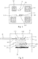
- Figures 5 and 6 respectively show the top and bottom sides of the display face 52 of the housing unit 5 when the belt strap 3 has been partially spooled out, but the tongue 4 is unbuckled.
- the darkened section 132 of the lock indicator element 13 is not visible and hence the lock indicator 9 is negative.
- the darkened section 142 of the strap indicator element 14 is visible through its aperture 111 indicating that a sufficient length of strap 3 has been withdrawn for securing around a body.
- Figures 7 and 8 respectively show the top and bottom sides of the display face 52 when the belt strap 3 has been secured around a body and the tongue 4 has been locked into the buckle 2.
- the darkened sections 132,142 of both the lock indicator element 13 and the strap indicator element 14 are displayed.
- the combination of both the positive lock indicator 9 and the strap indicator 11 indicate that the seatbelt is secured appropriately.
- this indicator information may therefore be used to confirm that safety requirements are being adhered to.
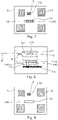
- Figure 9 shows the display face 52 when the belt strap 3 is not fitted around a body, but the tongue 4 has instead been locked directly into the buckle 2.
- the lock indicator 9 indicates positive locking
- the strap indicator 11 shows the length of strap dispensed is below the threshold.
- this indicator combination may be used to determine that the seat belt is not being used correctly. For instance, if it is concurrently determined that the seat 1 is occupied, it indicates that the strap 3 is fitted behind a users' back. In response, the processor 6 may prompt an audible warning or reminder to occupants of the vehicle to secure their seat belt correctly.
- the lock indicator 9 may indicate the tongue 4 is not locked, but the strap indicator 11 shows the length of strap dispensed is above the threshold. If it is concurrently determined that the seat 1 is occupied in this situation, this then indicates that a user as pulled out the strap but is merely holding the tongue 4 rather than attaching it to the buckle.
- the processor 6 processes images from camera 7, together with any other camera or sensor inputs, to determine the configuration of seats 1 in the vehicle, which seats are occupied, and the status of the seat belts on the occupied seats. As such, when a seat is identified as occupied, but the combination of the lock and strap indicators indicate the seat belt is not secured correctly, the processor 6 may prompt a warning or alarm to notify the occupants so that they may correct the issue.
- the apparatus may provide for the effective determination of seat belt compliance in a wide variety of seat configurations, without requiring electrical wire harnesses to feed each seat independently.
- the seats themselves may be provided as passive seats, without any internal electronic components. This therefore simplifies their construction, as well as their connection to the vehicle itself. This is especially useful for vehicles with reconfigurable seats.
- the indicators can also be maintained in all normal usage scenarios, particularly since, in most vehicles, internal cameras are mounted on the ceiling. As such, the status of the seat belt can be detected even in cases where the passenger is wearing a jacket or is covered by a blanket.
- the indicators can use simplified markings to convey seat belt status information
- the resolution of the camera imager can be relatively low.
- the algorithms required to interpret this information from the camera images may also be simplified compared to prior art systems which attempt to interpret the belt status based on the seating and belt position of occupants.
- the indicator unit has been incorporated into the same unit as the retractor housing 52, it will be understood that other arrangements are possible.
- the indicator unit may be provided separately to the retractor.
- the indicator unit may also be mounted to other sections of the upper region of the seat back, such as on the headrest 104.
- the lock and strap indicators may be separated.
- the retractor 51 is incorporated into the sides or ceiling.
- the indicator apparatus may be distributed with the strap indicator 11 located with the retractor 51, and the lock indicator 9 mounted to the seat 1.
- the illustrative embodiment has been implemented alongside a camera-based occupancy detection system, it will be understood that other occupancy detection methodologies may alternatively be used.
- the seats may include a PODS system, albeit that this would require the incorporation of electronics into the seat itself.
- the illustrative embodiment incorporates locator markers 10, such markers may not be required.
- the indicators 9,11 may be in a limited number of positions and therefore the image recognition process may only need to focus on a limited field of view to read the indicators' status.
Landscapes
- Engineering & Computer Science (AREA)
- Automation & Control Theory (AREA)
- Mechanical Engineering (AREA)
- Automotive Seat Belt Assembly (AREA)
Abstract
Description
- The present disclosure relates to a safety apparatus for indicating the usage state of a seat belt. The present disclosure is particularly relevant to vehicle seat belt safety systems.
- Modern vehicles include ever increasing numbers of safety devices and systems, motivated not only by regulatory pressures but also consumer demand for improved road safety. One common feature is to provide a seat belt reminder or safety warning system for ensuring that occupants of a vehicle have buckled their seat belts. Initially, this system was provided only in respect of the first row of seats of a vehicle, and in some countries this feature has become a regulatory requirement for all new vehicles. However, as both regulatory trends and consumer expectations are directed toward increased safety compliance, there is a growing demand to provide seat belt reminder systems which cover every seat in a vehicle. For example, parents often wish to be alerted if a child in a passenger seat has unbuckled their belt.
- Conventional seat belt reminder systems are normally based on a combination of a PODS (Pressure Occupant Detection System) and a lock switch system. The PODS is fitted into the vehicle seat base and is used to detect an occupant by detecting their weight on the seat. The lock switch system is fitted into the seat belt buckle and confirms once the seat belt tongue has been locked into place. These systems then feed a safety controller to issue a reminder if a seat is occupied but the seat belt is unbuckled. There are however a number of shortcomings with this conventional system.
- In this respect, PODS and lock switch systems require an electrical harness to be connected to every vehicle seat that is to be covered by the system. Although this is manageable for the front row seats, it becomes much more challenging when the system is to be extended to cover the second, third, or further rows of seats in larger vehicles. In this situation, additional wire harness cabling and connection terminals are needed to connect the components, which adds considerably to the expense and complexity of the system. However, the issue becomes even more complex in vehicles which have reconfigurable seats, such as in people carriers and larger sports utility vehicles. For example, some vehicles allow the second or later row seats to be individually moved forward or back, or flipped around to face the opposite direction, or even removed entirely. To accommodate this functionality, whilst also providing a conventional seat belt reminder system, would require connector terminals for the PODS and lock switch sensors to be provided on the vehicle floor for every possible seat configuration. This is typically not viable for cost reasons.
- In recent years, new seat belt reminder systems have been proposed which utilise cameras within the vehicle's interior, and then determine seat occupancy and seat belt compliance based on image recognition processing using a neural network. To improve reliability, some systems also make use of patterns printed on the seat belt strap which can be more easily identified in the image and thereby help to confirm that the strap has been fitted across the chest of an occupant. In principle, such camera-based systems could allow the occupancy and seat belt status to be determined without needing PODS or lock switch sensors to be provided in every seat. However, in practice, such systems are often not sufficiently reliable.
- In this respect, a limitation of camera-based systems is that they require the seat belt and the buckle to be visible to the camera. However, these parts are prone to being covered by the nature of their operation. For example, jackets, blankets and other objects will often be on an occupant's lap or thrown on adjacent seats, where they may cover part or all of the seat belt or the buckle. Obstructing the camera's field of view in this way makes it extremely difficult for the neural network to interpret the image data consistently. As such, the functionality of the system may be compromised. To address this, camera-based systems are often used in conjunction with PODS and/or lock switch sensors to improve overall reliability. However, this only leads to even greater cost and complexity. A further drawback is that, in vehicles which do have reconfigurable seats, it is relatively complex to hardcode or train the neural network to be able to operate effectively in all possible seating combinations. Again, this leads to increased cost and processing overheads.
- A further complexity relates to a behaviour pattern of some occupants to attempt to circumvent seat belt safety systems. For example, an occupant may connect the tongue directly into the buckle before they sit down, so that the strap is deployed behind their back once they are seated. Equally, tamper devices are available for locking into the buckle to replicate the tongue being locked into place. Conventional PODS and lock switch systems cannot detect this type of behaviour, and although camera-based systems should provide some detection, this is limited by requiring the seat belt strap to be visible. For safety regulators, this potential for misuse presents a problem because safety systems can only be deemed effective to the extent that they are used properly and consistently.
- There therefore remains a need for an improved seat belt safety warning system.
- The present disclosure concerns a vehicle camera assembly and method of assembling a vehicle camera assembly.
- According to a first aspect, there is provided a safety apparatus for indicating the usage state of a seat belt having a strap spooled from a retractor and being lockable to a buckle by a tongue, the apparatus including: an indicator unit for mounting to an upper region of a seat; a lock indicator provided on the indicator unit and being operably connectable to the buckle for indicating a state when the tongue has been locked into the buckle; and a strap indicator for indicating a state when a spooled length of the strap exceeds a threshold corresponding to a predetermined minimum length of strap needed to secure a body with the seat belt; and wherein the lock indicator and the strap indicator are detectable by a camera.
- In this way, an indication of the locking and belt strap status of a seat may be determined by processing images from the camera. By combining this with seat occupancy information, it may therefore be determined whether the seat belt is being used correctly, and provide for an alert to be issued in circumstances where it isn't. Importantly, by mounting the indicator unit to an upper region of the seat, the indicators may be positioned above an occupant's shoulders, thereby mitigating the risk of obstruction by clothing or other objects. Furthermore, by allowing for camera-based determination, greater flexibility is achieved in terms of allowing seats to be reconfigured, whilst minimising the costs and complexity associated with additional wire harnesses.
- In embodiments, the strap indicator is provided on the indicator unit. In this way, a single indicator unit may be provided, thereby narrowing the field of view required for image analysis to determine the status of the indicators.
- In embodiments, the indicator unit includes a mounting for securing the indicator unit to one of a shoulder of the seat and a headrest.
- In embodiments, the strap indicator includes a strap indicator element mechanically movable from a negative position to a positive position for indicating the spooled length of strap has exceeded the threshold. In this way, the indicator does not require a power source or connection to the vehicle's electronic systems.
- In embodiments, movement of the strap indicator element to a positive position exposes a visible marker for detection by the camera.
- In embodiments, the strap indicator element is connected to the retractor by a spool indicator mechanism for moving the strap indicator element proportionally as the strap is spooled from the retractor. In this way, the strap indicator element may be used to gauge the length of strap drawn from the retractor.
- In embodiments, the lock indicator includes a lock indicator element mechanically movable from a negative position to a positive position for indicating the tongue has been locked into the buckle.
- In embodiments, the lock indicator element is operably connectable to the buckle by a mechanical linkage for moving the lock indicator element into the positive position when the tongue locks into the buckle. In this way, the indicator does not require a power source or connection to the vehicle's electronic systems.
- In embodiments, the mechanical linkage includes a seat section for securing within the interior the seat between the buckle and the indicator unit. In this way, the mechanical connection may be built into the seat unit itself.
- In embodiments, the seat section includes a Bowden cable. In this way, an inexpensive mechanism is provided for actuating the lock indicator.
- In embodiments, movement of the lock indicator element to a positive position exposes a visible marker for detection by the camera.
- In embodiments, the safety apparatus, further includes a locator marking provided on the indicator unit for detection by the camera. In this way, the location of the indicator unit may be more easily identified from a camera image based on the detection of the locator markings.
- In embodiments, the locator marking includes one or more orientation features for determining seat orientation based on an image detected by the camera. In this way, the orientation of the indicator unit, and hence the seat itself, may be more easily determined through image recognition based on the detected orientation of the markings.
- In embodiments, the safety apparatus further includes: a camera unit for detecting an image of the lock indicator and the strap indicator; and a processor for processing the image to identify the state of the lock indicator and the strap indicator. In this way, the apparatus may be provided as a seat belt safety system.
- In embodiments, the processor further includes an occupancy detector for detecting an occupant in the seat.
- Illustrative embodiments will now be described with reference to the accompanying drawings in which:
-
Figure 1 shows an isometric view of a car seat incorporating an apparatus according to an embodiment; -
Figure 2 shows a view of the back part of the car seat showing the lock indicator linkage; -
Figure 3 shows the display face of the housing unit when the belt strap is retracted and the tongue is unbuckled; -
Figure 4 shows the back face of the housing unit when the seat belt is in the state shown inFigure 3 ; -
Figure 5 shows the display face of the housing unit when the belt strap has been partially spooled out but the tongue is unbuckled; -
Figure 6 shows the back face of the housing unit when the seat belt is in the state shown inFigure 5 ; -
Figure 7 shows the display face of the housing unit when the belt strap has been secured around a body and the tongue has been locked into the buckle; -
Figure 8 shows the back face of the housing unit when the seat belt is in the state shown inFigure 7 ; -
Figure 9 shows the display face of the housing unit when the belt strap is not fitted around a body and the tongue has been locked into the buckle. -
Figure 1 shows avehicle seat 1 incorporating the seat belt safety apparatus according to an illustrative embodiment. The seat includes abase 101, aback part 102, and aheadrest 104 mounted to theshoulder region 103 of theback part 102. As such, theshoulder region 103 and theheadrest 104 form an upper region of theseat 1. - The seat belt includes a
strap 3, which is fixed at one end to a side of theseat base 101 by a strap fixing 31 and is spooled onto aretractor 51 housed withinhousing unit 5 mounted to the seat'sshoulder region 103 at the other end. Atongue 4 is slidably coupled to thestrap 3 between the strap fixing 31 and theretractor 51. Abuckle 2 for receiving and locking thetongue 4 is provided on the seat base, at the side opposite to the strap fixing 31. As such, to secure the belt in use, an occupant may draw out a length of strap webbing from theretractor 51 and lock thetongue 4 into thebuckle 2. This thereby forms a three-point harness between the strap fixing 31, theretractor 51 and thebuckle 2, with thestrap 3 fitted across both the occupant's chest and lap. - In addition to housing the
retractor 51, thehousing unit 5 also includes adisplay face 52 on an upper surface for displaying a number of indicators, as is described in further detail below. As such, thehousing unit 5 provides an indicator unit for indicating seat belt status information. - The seat belt safety apparatus further includes a camera 7 and a
processor 6 which processes images from the camera 7. The camera 7 andprocessor 6 are integrated into the vehicle, with theprocessor 6 being part of the vehicle's embedded safety control systems. The camera 7 is mounted to the ceiling of the vehicle's interior and is directed such that thedisplay face 52 of thehousing unit 5 is within its field of view. As such, the indicators provided on thedisplay face 52 are detectable by the camera. In this respect, the indicators may be visible to the camera in the visible light spectrum and/or, for instance, in the infrared spectrum. In the latter case, embodiments may include an infrared emitter within the camera 7 assembly, with the indicators provided as an infrared reflective surface. The use of infrared may allow the indicators to be provided without compromising the aesthetics of the vehicle interior. - The
processor 6 processes images from the camera 7 to identify the indicators provided on thedisplay face 52 of thehousing unit 5. In embodiments, theprocessor 6 includes a neural network for this image processing. Theprocessor 6 may also receive feeds from a number of further cameras or other sensors for interpreting other safety input information. In this embodiment, theprocessor 6 is further used to implement a camera-based occupancy detection system. For this, theprocessor 6 receives a camera input and uses image recognition to identify when people are seated in each of the seats. -
Figure 2 shows a partially exposed interior front view of theback part 102 of theseat 1. Alock indicator linkage 8 is provided in the seat interior for mechanically linking the locking mechanism in thebuckle 2 to a lock indicator in thehousing unit 5. As such, when thebuckle 2 is locked by the insertion of thetongue 4, this is translated into an operation of thelock indicator linkage 8, which in turn alters the lock indicator, as is described in further detail below. In this embodiment, thelock indicator linkage 8 is provided as a Bowden cable mechanism, wherein a flexible inner actuator cable is used to transmit movements associated with the locking and unlocking of the buckle mechanism through a hollow outer cable. -
Figures 3 and 4 respectively show the top and bottom sides of thedisplay face 52 of thehousing unit 5. In these figures, thebelt strap 3 is retracted and thetongue 4 is unbuckled. As shown inFigure 3 , the exposed top side of thedisplay face 52 includes thelock indicator 9, astrap indicator 11, and a plurality oflocator markers 10. - The
lock indicator 9 includes anaperture 91 provided in thedisplay face 52, through which alock indicator element 13 is exposed. On the bottom side of the display face, as shown inFigure 4 , thelock indicator element 13 is slidably received within atrack 12 and is connected at one end to theactuator cable 18 of thelock indicator linkage 8. Thelock indicator element 13 includes adarkened section 132 for indicating the buckle is locked and awhite section 131 for indicating the buckle is unlocked. Actuation of the buckle locking mechanism causes theactuator cable 18 to move thelock indicator element 13 along thetrack 12 from a first position where thewhite section 131 is exposed through theaperture 91, to a second position where thedarkened section 132 is exposed. As such, thebelt lock indicator 9 provides a visual indicator when the buckle is locked in that theaperture 91 on thedisplay face 52 shows thedark section 132. - The
strap indicator 11 includes anelongated aperture 111 in thedisplay face 52, thorough which anstrap indicator element 14 is exposed. On the bottom side of thedisplay face 52, as shown inFigure 4 , thestrap indicator element 14 is slidably received within atrack 17. Thestrap indicator element 14 is coupled to theseat belt retractor 51 such that it is moved back and forth along thetrack 17 in response to thestrap 3 being spooled into and out from theretractor 51. In this embodiment, this spool indicator mechanism includes alead screw 16 which is coupled to a leadscrew nut connector 15 attached to thestrap indicator element 14. As the retractor spool is rotated, a gear arrangement (not shown) causes rotation of thelead screw 16, which is translated to a linear movement of the leadscrew nut connector 15 and, in turn, movement of thestrap indicator element 14. As such, thestrap indicator element 14 is moved proportionally with the length ofstrap 3 spooled out from theretractor 51. - The
strap indicator element 14 further includes awhite section 141 and adarkened section 142, with thedarkened section 142 marking the point at which a minimum threshold length ofstrap 3 has been spooled from theretractor 51. The predetermined threshold is set for indicating when a sufficient length ofstrap 3 has been dispensed for securing around a body. In use, as thestrap 3 is fed out from theretractor 51, thestrap indicator element 14 is moved along thetrack 17 from a first position where thewhite section 141 is exposed through the strap indicator'saperture 111, to a second position where thedarkened section 142 is exposed. As thestrap 3 continues to feed out from theretractor 51, a larger proportion of thedarkened section 142 is visible through theaperture 111. The size of the exposeddarkened section 142 thereby provides a gauge for indicating not only that the threshold has been reached, but also the length ofstrap 3 dispensed. This length indicator may be interpreted by theprocessor 6 to provide data on the size of the occupant and therefore may be used to determine how the seatbelt is being used. For example, if the determined length ofstrap 3 is near to a maximum extension, this may be used as an indicator that a rear facing child car seat has been installed on the seat. - The plurality of
locator markers 10 are also provided. Primarily, thelocator markers 10 facilitate the easy detection of thedisplay face 52 in the image generated by the camera 7. In this embodiment, thelocator markers 10 follow a QR code standard, with three position markers and a smaller alignment marker. However, it will be understood that other styles of markers which provide an unambiguously identifiable pattern in the output image may alternatively be used. - The
locator markers 10 further provide a reference indicator for identifying and interpreting thelock indicator 9 andstrap indicator 11 by the image processing algorithms. In addition, because thelocator markers 10 provide an orientation indicator, they may also be used by theprocessor 6 to determine the position, configuration, and orientation of the seats within the vehicle. This output may be used to provide seat configuration information for use in conjunction with the camera-based occupancy detection system. That is, data on where the seats are positioned may be used by theprocessor 6 to facilitate the identification of passengers in the camera image by limiting the regions of interest to areas where the seats are present. This may thereby improve the accuracy of the camera-based occupancy detection system. - The operation of the lock and strap indicators will now be described in further detail.
Figures 5 and 6 respectively show the top and bottom sides of thedisplay face 52 of thehousing unit 5 when thebelt strap 3 has been partially spooled out, but thetongue 4 is unbuckled. In this position, thedarkened section 132 of thelock indicator element 13 is not visible and hence thelock indicator 9 is negative. However, thedarkened section 142 of thestrap indicator element 14 is visible through itsaperture 111 indicating that a sufficient length ofstrap 3 has been withdrawn for securing around a body. -
Figures 7 and 8 respectively show the top and bottom sides of thedisplay face 52 when thebelt strap 3 has been secured around a body and thetongue 4 has been locked into thebuckle 2. In this position, the darkened sections 132,142 of both thelock indicator element 13 and thestrap indicator element 14 are displayed. As such, the combination of both thepositive lock indicator 9 and thestrap indicator 11 indicate that the seatbelt is secured appropriately. When it is concurrently determined that theseat 1 is occupied, this indicator information may therefore be used to confirm that safety requirements are being adhered to. -
Figure 9 shows thedisplay face 52 when thebelt strap 3 is not fitted around a body, but thetongue 4 has instead been locked directly into thebuckle 2. In this scenario, whilst thelock indicator 9 indicates positive locking, thestrap indicator 11 shows the length of strap dispensed is below the threshold. As such, this indicator combination may be used to determine that the seat belt is not being used correctly. For instance, if it is concurrently determined that theseat 1 is occupied, it indicates that thestrap 3 is fitted behind a users' back. In response, theprocessor 6 may prompt an audible warning or reminder to occupants of the vehicle to secure their seat belt correctly. - In another scenario, the
lock indicator 9 may indicate thetongue 4 is not locked, but thestrap indicator 11 shows the length of strap dispensed is above the threshold. If it is concurrently determined that theseat 1 is occupied in this situation, this then indicates that a user as pulled out the strap but is merely holding thetongue 4 rather than attaching it to the buckle. - In use, the
processor 6 processes images from camera 7, together with any other camera or sensor inputs, to determine the configuration ofseats 1 in the vehicle, which seats are occupied, and the status of the seat belts on the occupied seats. As such, when a seat is identified as occupied, but the combination of the lock and strap indicators indicate the seat belt is not secured correctly, theprocessor 6 may prompt a warning or alarm to notify the occupants so that they may correct the issue. - Accordingly, the apparatus may provide for the effective determination of seat belt compliance in a wide variety of seat configurations, without requiring electrical wire harnesses to feed each seat independently. Furthermore, the seats themselves may be provided as passive seats, without any internal electronic components. This therefore simplifies their construction, as well as their connection to the vehicle itself. This is especially useful for vehicles with reconfigurable seats.
- As the arrangement also allows the indicators to be located on the upper region of the seat, visibility by the camera system can also be maintained in all normal usage scenarios, particularly since, in most vehicles, internal cameras are mounted on the ceiling. As such, the status of the seat belt can be detected even in cases where the passenger is wearing a jacket or is covered by a blanket.
- Finally, as the indicators can use simplified markings to convey seat belt status information, the resolution of the camera imager can be relatively low. The algorithms required to interpret this information from the camera images may also be simplified compared to prior art systems which attempt to interpret the belt status based on the seating and belt position of occupants.
- It will be understood that the embodiment illustrated above shows an application only for the purposes of illustration. In practice, embodiments may be applied to many different configurations, the detailed embodiments being straightforward for those skilled in the art to implement.
- In this connection, for example, although in the above illustrative embodiment, the indicator unit has been incorporated into the same unit as the
retractor housing 52, it will be understood that other arrangements are possible. For example, the indicator unit may be provided separately to the retractor. The indicator unit may also be mounted to other sections of the upper region of the seat back, such as on theheadrest 104. - Furthermore, in some embodiments, the lock and strap indicators may be separated. For example, in some vehicles, the
retractor 51 is incorporated into the sides or ceiling. In this scenario, the indicator apparatus may be distributed with thestrap indicator 11 located with theretractor 51, and thelock indicator 9 mounted to theseat 1. - Moreover, although the illustrative embodiment has been implemented alongside a camera-based occupancy detection system, it will be understood that other occupancy detection methodologies may alternatively be used. For example, the seats may include a PODS system, albeit that this would require the incorporation of electronics into the seat itself.
- Finally, although the illustrative embodiment incorporates
locator markers 10, such markers may not be required. For example, in vehicles with fixed seat locations, theindicators
Claims (15)
- Safety apparatus for indicating the usage state of a seat belt having a strap spooled from a retractor and being lockable to a buckle by a tongue, the apparatus comprising:an indicator unit for mounting to an upper region of a seat;a lock indicator provided on the indicator unit and being operably connectable to the buckle for indicating a state when the tongue has been locked into the buckle; anda strap indicator for indicating a state when a spooled length of the strap exceeds a threshold corresponding to a predetermined minimum length of strap needed to secure a body with the seat belt; andwherein the lock indicator and the strap indicator are detectable by a camera.
- Safety apparatus according to claim 1, wherein the strap indicator is provided on the indicator unit.
- Safety apparatus according to claim 1 or 2, wherein the indicator unit comprises a mounting for securing the indicator unit to one of a shoulder of the seat and a headrest.
- Safety apparatus according to any preceding claim, wherein the strap indicator comprises a strap indicator element mechanically movable from a negative position to a positive position for indicating the spooled length of strap has exceeded the threshold.
- Safety apparatus according to claim 4, wherein movement of the strap indicator element to a positive position exposes a visible marker for detection by the camera.
- Safety apparatus according to claim 4 or 5, wherein the strap indicator element is connected to the retractor by a spool indicator mechanism for moving the strap indicator element proportionally as the strap is spooled from the retractor.
- Safety apparatus according to any preceding claim, wherein the lock indicator comprises a lock indicator element mechanically movable from a negative position to a positive position for indicating the tongue has been locked into the buckle.
- Safety apparatus according to claim 6, wherein the lock indicator element is operably connectable to the buckle by a mechanical linkage for moving the lock indicator element into the positive position when the tongue locks into the buckle.
- Safety apparatus according to claim 8, wherein the mechanical linkage comprises a seat section for securing within the interior the seat between the buckle and the indicator unit.
- Safety apparatus according to claim 9, wherein seat section comprises a Bowden cable.
- Safety apparatus according to any one of claims 7 to 10, wherein movement of the lock indicator element to a positive position exposes a visible marker for detection by the camera.
- Safety apparatus according to any preceding claim, further comprising:
a locator marking provided on the indicator unit for detection by the camera. - Safety apparatus according to claim 12, wherein the locator marking comprises one or more orientation features for determining seat orientation based on an image detected by the camera.
- Safety apparatus according to any preceding claim, further comprising:a camera unit for detecting an image of the lock indicator and the strap indicator; anda processor for processing the image to identify the state of the lock indicator and the strap indicator.
- Safety apparatus according to claim 14, wherein the processor further comprises an occupancy detector for detecting an occupant in the seat.
Applications Claiming Priority (1)
| Application Number | Priority Date | Filing Date | Title |
|---|---|---|---|
| GB2100619.2A GB2602830B (en) | 2021-01-18 | 2021-01-18 | Safety apparatus for indicating the usage state of a seat belt |
Publications (2)
| Publication Number | Publication Date |
|---|---|
| EP4029739A1 true EP4029739A1 (en) | 2022-07-20 |
| EP4029739B1 EP4029739B1 (en) | 2024-05-29 |
Family
ID=74678933
Family Applications (1)
| Application Number | Title | Priority Date | Filing Date |
|---|---|---|---|
| EP21215512.1A Active EP4029739B1 (en) | 2021-01-18 | 2021-12-17 | Safety apparatus for indicating the usage state of a seat belt |
Country Status (4)
| Country | Link |
|---|---|
| US (1) | US12384326B2 (en) |
| EP (1) | EP4029739B1 (en) |
| CN (1) | CN114802094B (en) |
| GB (1) | GB2602830B (en) |
Families Citing this family (5)
| Publication number | Priority date | Publication date | Assignee | Title |
|---|---|---|---|---|
| EP3848256A1 (en) | 2020-01-07 | 2021-07-14 | Aptiv Technologies Limited | Methods and systems for detecting whether a seat belt is used in a vehicle |
| US12122313B2 (en) * | 2021-02-05 | 2024-10-22 | Magna Electronics, Llc | Seatbelt buckle engagement detection |
| US11938878B1 (en) * | 2021-06-25 | 2024-03-26 | Zoox, Inc. | Occupant restraint system and method |
| US11975683B2 (en) | 2021-06-30 | 2024-05-07 | Aptiv Technologies AG | Relative movement-based seatbelt use detection |
| US20260061839A1 (en) * | 2024-09-04 | 2026-03-05 | Textron Inc. | Systems and methods for integrated accessory vehicle control management |
Citations (3)
| Publication number | Priority date | Publication date | Assignee | Title |
|---|---|---|---|---|
| CN2756044Y (en) * | 2004-12-10 | 2006-02-08 | 明门实业股份有限公司 | Multi-directional security fasteners |
| US20170291576A1 (en) * | 2016-04-11 | 2017-10-12 | Ford Global Technologies, Llc | Belt assembly including plus-two-point belt reminder |
| US10773683B1 (en) * | 2019-08-12 | 2020-09-15 | Ford Global Technologies, Llc | Occupant seatbelt status |
Family Cites Families (37)
| Publication number | Priority date | Publication date | Assignee | Title |
|---|---|---|---|---|
| DE10133759C2 (en) | 2001-07-11 | 2003-07-24 | Daimler Chrysler Ag | Belt guide recognition with image processing system in the vehicle |
| DE10326840A1 (en) | 2003-06-14 | 2004-12-30 | Lux, Peter, Dr. | Vehicle seat device/method for recognizing occupancy of vehicle seats has a TV camera directed at the seat and a lighting unit with a clearance from the camera to light up a pattern to be evaluated |
| FR2877279B1 (en) | 2004-11-03 | 2008-06-27 | Faurecia Sieges Automobile | SYSTEM FOR DETECTING THE PRESENCE OF AN OCCUPANT ON A SEAT OF A MOTOR VEHICLE, SEAT ADAPTED TO THIS SYSTEM AND VEHICLE COMPRISING SUCH A SYSTEM |
| JP2007055294A (en) | 2005-08-22 | 2007-03-08 | Tokai Rika Co Ltd | Occupant detection apparatus for vehicle |
| JP4856506B2 (en) * | 2006-09-14 | 2012-01-18 | 本田技研工業株式会社 | Vehicle seat belt device |
| DE102007008602A1 (en) | 2007-02-22 | 2007-11-22 | Daimlerchrysler Ag | Recoil holding system used for vehicle seat comprises a safety belt with a roller for generating the safety belt and a rotation sensor for specifying the relative length and tension required for the safety belt |
| JP2008261749A (en) | 2007-04-12 | 2008-10-30 | Takata Corp | Occupant detection device, actuator control system, seat belt system, and vehicle |
| US20090058061A1 (en) | 2007-08-30 | 2009-03-05 | Fuisz Richard C | System for providing an indication indicative of whether or not a seat belt of a vehicle occupant is fastened |
| US8600622B2 (en) * | 2007-10-30 | 2013-12-03 | Ford Global Technologies, Llc | Intelligent arrangement buckle switch for seat belts |
| JP2010113506A (en) | 2008-11-06 | 2010-05-20 | Aisin Aw Co Ltd | Occupant position detection device, occupant position detection method, and occupant position detection program |
| US8611608B2 (en) | 2011-08-23 | 2013-12-17 | Xerox Corporation | Front seat vehicle occupancy detection via seat pattern recognition |
| CN104417489B (en) | 2013-08-29 | 2017-07-11 | 同观科技(深圳)有限公司 | A kind of car belt detection method and car belt detection means |
| JP6372986B2 (en) | 2013-09-26 | 2018-08-15 | 矢崎総業株式会社 | Seat belt wearing state display device |
| EP2937251B1 (en) | 2014-04-24 | 2017-07-12 | Volvo Car Corporation | Seat belt position detecting system and method |
| EP3023293B1 (en) * | 2014-11-20 | 2017-12-27 | Britax Römer Kindersicherheit GmbH | Child safety seat |
| US9650016B2 (en) | 2014-12-04 | 2017-05-16 | GM Global Technology Operations LLC | Detection of seatbelt position in a vehicle |
| CN104700068A (en) | 2014-12-17 | 2015-06-10 | 安徽清新互联信息科技有限公司 | SVM based detection method of safety belt of driver |
| CN105109448A (en) | 2015-08-26 | 2015-12-02 | 安徽工程大学 | System for detecting whether automobile safety belt is worn correctly and detection method of system |
| CN105946786B (en) | 2016-05-06 | 2018-12-07 | 厦门理工学院 | A kind of detection method, system for prompting and control method that safety belt specification is worn |
| WO2018042536A1 (en) * | 2016-08-31 | 2018-03-08 | 東芝デジタルソリューションズ株式会社 | Wearing detection device, image pickup device, restraint device, and wearing detection program |
| CN106494349A (en) * | 2016-10-25 | 2017-03-15 | 深圳市元征科技股份有限公司 | A kind of seat belt system alarm method and device |
| DE102016014867A1 (en) | 2016-12-14 | 2017-06-01 | Daimler Ag | Method for determining a belt status |
| US10611335B2 (en) | 2017-05-15 | 2020-04-07 | Joyson Safety Acquisition LLC | Detection and monitoring of occupant seat belt |
| US9878689B1 (en) * | 2017-06-30 | 2018-01-30 | Zoox, Inc. | Seatbelt system including occupant detector |
| US10339401B2 (en) | 2017-11-11 | 2019-07-02 | Bendix Commercial Vehicle Systems Llc | System and methods of monitoring driver behavior for vehicular fleet management in a fleet of vehicles using driver-facing imaging device |
| US10501048B2 (en) | 2018-01-19 | 2019-12-10 | Ford Global Technologies, Llc | Seatbelt buckling detection |
| CN110065433A (en) * | 2018-01-24 | 2019-07-30 | 天合汽车科技(上海)有限公司 | Safety belt assembly for motor vehicle and the safety belt luminescent system for motor vehicle |
| US10953850B1 (en) | 2018-04-05 | 2021-03-23 | Ambarella International Lp | Seatbelt detection using computer vision |
| US11046273B2 (en) * | 2019-01-22 | 2021-06-29 | GM Global Technology Operations LLC | Seat belt status determining system and method |
| CN109886205B (en) | 2019-02-25 | 2023-08-08 | 苏州清研微视电子科技有限公司 | Real-time safety belt monitoring method and system |
| US10850702B2 (en) * | 2019-03-18 | 2020-12-01 | Pony Ai Inc. | Vehicle seat belt monitoring |
| US10691955B1 (en) | 2019-04-02 | 2020-06-23 | Boeing Company, The | Aircraft cabin artificial intelligence crew assistance |
| CN113874259B (en) * | 2019-04-04 | 2023-11-03 | 乔伊森安全系统收购有限责任公司 | Detection and monitoring of active optical retroreflectors |
| DE102019211200A1 (en) * | 2019-07-29 | 2021-02-04 | Zf Friedrichshafen Ag | Method for detecting incorrect use of a belt system of a motor vehicle, as well as a control device for it and the motor vehicle |
| US20210086715A1 (en) | 2019-09-25 | 2021-03-25 | AISIN Technical Center of America, Inc. | System and method for monitoring at least one occupant within a vehicle using a plurality of convolutional neural networks |
| JP6730505B2 (en) | 2019-12-02 | 2020-07-29 | 東芝デジタルソリューションズ株式会社 | Mounting detection device, camera unit, and mounting detection program |
| CN111645629B (en) * | 2020-06-08 | 2021-07-13 | 中国第一汽车股份有限公司 | Safety belt unfastening reminding method and device, vehicle and storage medium |
-
2021
- 2021-01-18 GB GB2100619.2A patent/GB2602830B/en active Active
- 2021-12-17 EP EP21215512.1A patent/EP4029739B1/en active Active
- 2021-12-22 US US17/645,724 patent/US12384326B2/en active Active
- 2021-12-30 CN CN202111660489.1A patent/CN114802094B/en active Active
Patent Citations (3)
| Publication number | Priority date | Publication date | Assignee | Title |
|---|---|---|---|---|
| CN2756044Y (en) * | 2004-12-10 | 2006-02-08 | 明门实业股份有限公司 | Multi-directional security fasteners |
| US20170291576A1 (en) * | 2016-04-11 | 2017-10-12 | Ford Global Technologies, Llc | Belt assembly including plus-two-point belt reminder |
| US10773683B1 (en) * | 2019-08-12 | 2020-09-15 | Ford Global Technologies, Llc | Occupant seatbelt status |
Also Published As
| Publication number | Publication date |
|---|---|
| US12384326B2 (en) | 2025-08-12 |
| EP4029739B1 (en) | 2024-05-29 |
| CN114802094B (en) | 2024-02-13 |
| US20220227331A1 (en) | 2022-07-21 |
| CN114802094A (en) | 2022-07-29 |
| GB202100619D0 (en) | 2021-03-03 |
| GB2602830B (en) | 2023-11-29 |
| GB2602830A (en) | 2022-07-20 |
Similar Documents
| Publication | Publication Date | Title |
|---|---|---|
| EP4029739B1 (en) | Safety apparatus for indicating the usage state of a seat belt | |
| EP1819554B1 (en) | Child seat detection system | |
| US10997440B2 (en) | Wearing detection apparatus, imaging apparatus, restraint device, and wearing detection program | |
| US7446652B2 (en) | Seatbelt usage detection system | |
| CN111194283B (en) | Detection and monitoring of passenger safety belts | |
| US9527477B1 (en) | Seat belt buckle tongue electromagnetic coupling with optional wireless sensor and/or actuator system | |
| US20050150705A1 (en) | Safety arrangement | |
| EP2937251A1 (en) | Seat belt position detecting system and method | |
| LU93261B1 (en) | Seat Belt Status Monitoring System | |
| CN104908705A (en) | System and method for seatbelt use monitoring | |
| US20090112408A1 (en) | Intelligent arrangement buckle switch for seat belts | |
| DE102022206760B4 (en) | Safety system for detecting misuse of a seat belt | |
| CN108622014B (en) | Robust seat belt usage sensor | |
| JP6730505B2 (en) | Mounting detection device, camera unit, and mounting detection program | |
| CN112168511B (en) | Restraint device for wheelchair occupant | |
| US7163075B2 (en) | Method and apparatus for detecting the presence of a rear facing infant seat | |
| EP2899062A1 (en) | Seat belt detection device for detecting the buckled state for a driver seat | |
| CN120813502A (en) | System for detecting incorrect use of a safety belt | |
| GB2622599A (en) | Method and system for detecting a seatbelt status of a vehicle seat | |
| JP2011126358A (en) | Reminder device of seat belt | |
| JP4423744B2 (en) | Air belt device | |
| TR202020693A1 (en) | SEAT BELT MISUSE PREVENTION SYSTEM AND A RELATED METHOD | |
| TR2023012434U5 (en) | A SEAT BELT TRACKING SYSTEM | |
| KR20210073683A (en) | Seat belt module |
Legal Events
| Date | Code | Title | Description |
|---|---|---|---|
| PUAI | Public reference made under article 153(3) epc to a published international application that has entered the european phase |
Free format text: ORIGINAL CODE: 0009012 |
|
| STAA | Information on the status of an ep patent application or granted ep patent |
Free format text: STATUS: THE APPLICATION HAS BEEN PUBLISHED |
|
| AK | Designated contracting states |
Kind code of ref document: A1 Designated state(s): AL AT BE BG CH CY CZ DE DK EE ES FI FR GB GR HR HU IE IS IT LI LT LU LV MC MK MT NL NO PL PT RO RS SE SI SK SM TR |
|
| STAA | Information on the status of an ep patent application or granted ep patent |
Free format text: STATUS: REQUEST FOR EXAMINATION WAS MADE |
|
| 17P | Request for examination filed |
Effective date: 20221125 |
|
| RBV | Designated contracting states (corrected) |
Designated state(s): AL AT BE BG CH CY CZ DE DK EE ES FI FR GB GR HR HU IE IS IT LI LT LU LV MC MK MT NL NO PL PT RO RS SE SI SK SM TR |
|
| GRAP | Despatch of communication of intention to grant a patent |
Free format text: ORIGINAL CODE: EPIDOSNIGR1 |
|
| STAA | Information on the status of an ep patent application or granted ep patent |
Free format text: STATUS: GRANT OF PATENT IS INTENDED |
|
| INTG | Intention to grant announced |
Effective date: 20240301 |
|
| GRAS | Grant fee paid |
Free format text: ORIGINAL CODE: EPIDOSNIGR3 |
|
| RAP1 | Party data changed (applicant data changed or rights of an application transferred) |
Owner name: APTIV TECHNOLOGIES AG |
|
| GRAA | (expected) grant |
Free format text: ORIGINAL CODE: 0009210 |
|
| STAA | Information on the status of an ep patent application or granted ep patent |
Free format text: STATUS: THE PATENT HAS BEEN GRANTED |
|
| AK | Designated contracting states |
Kind code of ref document: B1 Designated state(s): AL AT BE BG CH CY CZ DE DK EE ES FI FR GB GR HR HU IE IS IT LI LT LU LV MC MK MT NL NO PL PT RO RS SE SI SK SM TR |
|
| P01 | Opt-out of the competence of the unified patent court (upc) registered |
Effective date: 20240423 |
|
| REG | Reference to a national code |
Ref country code: CH Ref legal event code: EP |
|
| REG | Reference to a national code |
Ref country code: IE Ref legal event code: FG4D |
|
| REG | Reference to a national code |
Ref country code: DE Ref legal event code: R096 Ref document number: 602021013797 Country of ref document: DE |
|
| RAP4 | Party data changed (patent owner data changed or rights of a patent transferred) |
Owner name: APTIV TECHNOLOGIES AG |
|
| REG | Reference to a national code |
Ref country code: LT Ref legal event code: MG9D |
|
| REG | Reference to a national code |
Ref country code: NL Ref legal event code: MP Effective date: 20240529 |
|
| PG25 | Lapsed in a contracting state [announced via postgrant information from national office to epo] |
Ref country code: IS Free format text: LAPSE BECAUSE OF FAILURE TO SUBMIT A TRANSLATION OF THE DESCRIPTION OR TO PAY THE FEE WITHIN THE PRESCRIBED TIME-LIMIT Effective date: 20240929 |
|
| PG25 | Lapsed in a contracting state [announced via postgrant information from national office to epo] |
Ref country code: BG Free format text: LAPSE BECAUSE OF FAILURE TO SUBMIT A TRANSLATION OF THE DESCRIPTION OR TO PAY THE FEE WITHIN THE PRESCRIBED TIME-LIMIT Effective date: 20240529 |
|
| PG25 | Lapsed in a contracting state [announced via postgrant information from national office to epo] |
Ref country code: HR Free format text: LAPSE BECAUSE OF FAILURE TO SUBMIT A TRANSLATION OF THE DESCRIPTION OR TO PAY THE FEE WITHIN THE PRESCRIBED TIME-LIMIT Effective date: 20240529 Ref country code: FI Free format text: LAPSE BECAUSE OF FAILURE TO SUBMIT A TRANSLATION OF THE DESCRIPTION OR TO PAY THE FEE WITHIN THE PRESCRIBED TIME-LIMIT Effective date: 20240529 |
|
| PG25 | Lapsed in a contracting state [announced via postgrant information from national office to epo] |
Ref country code: GR Free format text: LAPSE BECAUSE OF FAILURE TO SUBMIT A TRANSLATION OF THE DESCRIPTION OR TO PAY THE FEE WITHIN THE PRESCRIBED TIME-LIMIT Effective date: 20240830 |
|
| REG | Reference to a national code |
Ref country code: AT Ref legal event code: MK05 Ref document number: 1690380 Country of ref document: AT Kind code of ref document: T Effective date: 20240529 |
|
| PG25 | Lapsed in a contracting state [announced via postgrant information from national office to epo] |
Ref country code: ES Free format text: LAPSE BECAUSE OF FAILURE TO SUBMIT A TRANSLATION OF THE DESCRIPTION OR TO PAY THE FEE WITHIN THE PRESCRIBED TIME-LIMIT Effective date: 20240529 |
|
| PG25 | Lapsed in a contracting state [announced via postgrant information from national office to epo] |
Ref country code: AT Free format text: LAPSE BECAUSE OF FAILURE TO SUBMIT A TRANSLATION OF THE DESCRIPTION OR TO PAY THE FEE WITHIN THE PRESCRIBED TIME-LIMIT Effective date: 20240529 |
|
| PG25 | Lapsed in a contracting state [announced via postgrant information from national office to epo] |
Ref country code: PL Free format text: LAPSE BECAUSE OF FAILURE TO SUBMIT A TRANSLATION OF THE DESCRIPTION OR TO PAY THE FEE WITHIN THE PRESCRIBED TIME-LIMIT Effective date: 20240529 |
|
| PG25 | Lapsed in a contracting state [announced via postgrant information from national office to epo] |
Ref country code: LV Free format text: LAPSE BECAUSE OF FAILURE TO SUBMIT A TRANSLATION OF THE DESCRIPTION OR TO PAY THE FEE WITHIN THE PRESCRIBED TIME-LIMIT Effective date: 20240529 |
|
| PG25 | Lapsed in a contracting state [announced via postgrant information from national office to epo] |
Ref country code: PL Free format text: LAPSE BECAUSE OF FAILURE TO SUBMIT A TRANSLATION OF THE DESCRIPTION OR TO PAY THE FEE WITHIN THE PRESCRIBED TIME-LIMIT Effective date: 20240529 Ref country code: NO Free format text: LAPSE BECAUSE OF FAILURE TO SUBMIT A TRANSLATION OF THE DESCRIPTION OR TO PAY THE FEE WITHIN THE PRESCRIBED TIME-LIMIT Effective date: 20240829 Ref country code: LV Free format text: LAPSE BECAUSE OF FAILURE TO SUBMIT A TRANSLATION OF THE DESCRIPTION OR TO PAY THE FEE WITHIN THE PRESCRIBED TIME-LIMIT Effective date: 20240529 Ref country code: IS Free format text: LAPSE BECAUSE OF FAILURE TO SUBMIT A TRANSLATION OF THE DESCRIPTION OR TO PAY THE FEE WITHIN THE PRESCRIBED TIME-LIMIT Effective date: 20240929 Ref country code: HR Free format text: LAPSE BECAUSE OF FAILURE TO SUBMIT A TRANSLATION OF THE DESCRIPTION OR TO PAY THE FEE WITHIN THE PRESCRIBED TIME-LIMIT Effective date: 20240529 Ref country code: GR Free format text: LAPSE BECAUSE OF FAILURE TO SUBMIT A TRANSLATION OF THE DESCRIPTION OR TO PAY THE FEE WITHIN THE PRESCRIBED TIME-LIMIT Effective date: 20240830 Ref country code: FI Free format text: LAPSE BECAUSE OF FAILURE TO SUBMIT A TRANSLATION OF THE DESCRIPTION OR TO PAY THE FEE WITHIN THE PRESCRIBED TIME-LIMIT Effective date: 20240529 Ref country code: ES Free format text: LAPSE BECAUSE OF FAILURE TO SUBMIT A TRANSLATION OF THE DESCRIPTION OR TO PAY THE FEE WITHIN THE PRESCRIBED TIME-LIMIT Effective date: 20240529 Ref country code: BG Free format text: LAPSE BECAUSE OF FAILURE TO SUBMIT A TRANSLATION OF THE DESCRIPTION OR TO PAY THE FEE WITHIN THE PRESCRIBED TIME-LIMIT Effective date: 20240529 Ref country code: AT Free format text: LAPSE BECAUSE OF FAILURE TO SUBMIT A TRANSLATION OF THE DESCRIPTION OR TO PAY THE FEE WITHIN THE PRESCRIBED TIME-LIMIT Effective date: 20240529 Ref country code: RS Free format text: LAPSE BECAUSE OF FAILURE TO SUBMIT A TRANSLATION OF THE DESCRIPTION OR TO PAY THE FEE WITHIN THE PRESCRIBED TIME-LIMIT Effective date: 20240829 |
|
| PG25 | Lapsed in a contracting state [announced via postgrant information from national office to epo] |
Ref country code: NL Free format text: LAPSE BECAUSE OF FAILURE TO SUBMIT A TRANSLATION OF THE DESCRIPTION OR TO PAY THE FEE WITHIN THE PRESCRIBED TIME-LIMIT Effective date: 20240529 |
|
| PG25 | Lapsed in a contracting state [announced via postgrant information from national office to epo] |
Ref country code: NL Free format text: LAPSE BECAUSE OF FAILURE TO SUBMIT A TRANSLATION OF THE DESCRIPTION OR TO PAY THE FEE WITHIN THE PRESCRIBED TIME-LIMIT Effective date: 20240529 |
|
| PG25 | Lapsed in a contracting state [announced via postgrant information from national office to epo] |
Ref country code: DK Free format text: LAPSE BECAUSE OF FAILURE TO SUBMIT A TRANSLATION OF THE DESCRIPTION OR TO PAY THE FEE WITHIN THE PRESCRIBED TIME-LIMIT Effective date: 20240529 |
|
| PG25 | Lapsed in a contracting state [announced via postgrant information from national office to epo] |
Ref country code: EE Free format text: LAPSE BECAUSE OF FAILURE TO SUBMIT A TRANSLATION OF THE DESCRIPTION OR TO PAY THE FEE WITHIN THE PRESCRIBED TIME-LIMIT Effective date: 20240529 |
|
| PG25 | Lapsed in a contracting state [announced via postgrant information from national office to epo] |
Ref country code: CZ Free format text: LAPSE BECAUSE OF FAILURE TO SUBMIT A TRANSLATION OF THE DESCRIPTION OR TO PAY THE FEE WITHIN THE PRESCRIBED TIME-LIMIT Effective date: 20240529 |
|
| PG25 | Lapsed in a contracting state [announced via postgrant information from national office to epo] |
Ref country code: SK Free format text: LAPSE BECAUSE OF FAILURE TO SUBMIT A TRANSLATION OF THE DESCRIPTION OR TO PAY THE FEE WITHIN THE PRESCRIBED TIME-LIMIT Effective date: 20240529 Ref country code: RO Free format text: LAPSE BECAUSE OF FAILURE TO SUBMIT A TRANSLATION OF THE DESCRIPTION OR TO PAY THE FEE WITHIN THE PRESCRIBED TIME-LIMIT Effective date: 20240529 |
|
| PG25 | Lapsed in a contracting state [announced via postgrant information from national office to epo] |
Ref country code: SM Free format text: LAPSE BECAUSE OF FAILURE TO SUBMIT A TRANSLATION OF THE DESCRIPTION OR TO PAY THE FEE WITHIN THE PRESCRIBED TIME-LIMIT Effective date: 20240529 |
|
| PG25 | Lapsed in a contracting state [announced via postgrant information from national office to epo] |
Ref country code: SM Free format text: LAPSE BECAUSE OF FAILURE TO SUBMIT A TRANSLATION OF THE DESCRIPTION OR TO PAY THE FEE WITHIN THE PRESCRIBED TIME-LIMIT Effective date: 20240529 Ref country code: SK Free format text: LAPSE BECAUSE OF FAILURE TO SUBMIT A TRANSLATION OF THE DESCRIPTION OR TO PAY THE FEE WITHIN THE PRESCRIBED TIME-LIMIT Effective date: 20240529 Ref country code: RO Free format text: LAPSE BECAUSE OF FAILURE TO SUBMIT A TRANSLATION OF THE DESCRIPTION OR TO PAY THE FEE WITHIN THE PRESCRIBED TIME-LIMIT Effective date: 20240529 Ref country code: EE Free format text: LAPSE BECAUSE OF FAILURE TO SUBMIT A TRANSLATION OF THE DESCRIPTION OR TO PAY THE FEE WITHIN THE PRESCRIBED TIME-LIMIT Effective date: 20240529 Ref country code: DK Free format text: LAPSE BECAUSE OF FAILURE TO SUBMIT A TRANSLATION OF THE DESCRIPTION OR TO PAY THE FEE WITHIN THE PRESCRIBED TIME-LIMIT Effective date: 20240529 Ref country code: CZ Free format text: LAPSE BECAUSE OF FAILURE TO SUBMIT A TRANSLATION OF THE DESCRIPTION OR TO PAY THE FEE WITHIN THE PRESCRIBED TIME-LIMIT Effective date: 20240529 |
|
| PG25 | Lapsed in a contracting state [announced via postgrant information from national office to epo] |
Ref country code: IT Free format text: LAPSE BECAUSE OF FAILURE TO SUBMIT A TRANSLATION OF THE DESCRIPTION OR TO PAY THE FEE WITHIN THE PRESCRIBED TIME-LIMIT Effective date: 20240529 |
|
| REG | Reference to a national code |
Ref country code: DE Ref legal event code: R097 Ref document number: 602021013797 Country of ref document: DE |
|
| PLBE | No opposition filed within time limit |
Free format text: ORIGINAL CODE: 0009261 |
|
| STAA | Information on the status of an ep patent application or granted ep patent |
Free format text: STATUS: NO OPPOSITION FILED WITHIN TIME LIMIT |
|
| PG25 | Lapsed in a contracting state [announced via postgrant information from national office to epo] |
Ref country code: SI Free format text: LAPSE BECAUSE OF FAILURE TO SUBMIT A TRANSLATION OF THE DESCRIPTION OR TO PAY THE FEE WITHIN THE PRESCRIBED TIME-LIMIT Effective date: 20240529 |
|
| 26N | No opposition filed |
Effective date: 20250303 |
|
| PG25 | Lapsed in a contracting state [announced via postgrant information from national office to epo] |
Ref country code: MC Free format text: LAPSE BECAUSE OF FAILURE TO SUBMIT A TRANSLATION OF THE DESCRIPTION OR TO PAY THE FEE WITHIN THE PRESCRIBED TIME-LIMIT Effective date: 20240529 |
|
| REG | Reference to a national code |
Ref country code: CH Ref legal event code: PL |
|
| PG25 | Lapsed in a contracting state [announced via postgrant information from national office to epo] |
Ref country code: LU Free format text: LAPSE BECAUSE OF NON-PAYMENT OF DUE FEES Effective date: 20241217 |
|
| PG25 | Lapsed in a contracting state [announced via postgrant information from national office to epo] |
Ref country code: SE Free format text: LAPSE BECAUSE OF FAILURE TO SUBMIT A TRANSLATION OF THE DESCRIPTION OR TO PAY THE FEE WITHIN THE PRESCRIBED TIME-LIMIT Effective date: 20240529 |
|
| REG | Reference to a national code |
Ref country code: BE Ref legal event code: MM Effective date: 20241231 |
|
| PG25 | Lapsed in a contracting state [announced via postgrant information from national office to epo] |
Ref country code: BE Free format text: LAPSE BECAUSE OF NON-PAYMENT OF DUE FEES Effective date: 20241231 |
|
| PG25 | Lapsed in a contracting state [announced via postgrant information from national office to epo] |
Ref country code: CH Free format text: LAPSE BECAUSE OF NON-PAYMENT OF DUE FEES Effective date: 20241231 |
|
| PG25 | Lapsed in a contracting state [announced via postgrant information from national office to epo] |
Ref country code: IE Free format text: LAPSE BECAUSE OF NON-PAYMENT OF DUE FEES Effective date: 20241217 |
|
| PGFP | Annual fee paid to national office [announced via postgrant information from national office to epo] |
Ref country code: DE Payment date: 20251117 Year of fee payment: 5 |
|
| PGFP | Annual fee paid to national office [announced via postgrant information from national office to epo] |
Ref country code: GB Payment date: 20251210 Year of fee payment: 5 |
|
| PGFP | Annual fee paid to national office [announced via postgrant information from national office to epo] |
Ref country code: FR Payment date: 20251202 Year of fee payment: 5 |