EP4029655A1 - Zusatzhandgriff für ein elektrowerkzeug - Google Patents
Zusatzhandgriff für ein elektrowerkzeug Download PDFInfo
- Publication number
- EP4029655A1 EP4029655A1 EP22150114.1A EP22150114A EP4029655A1 EP 4029655 A1 EP4029655 A1 EP 4029655A1 EP 22150114 A EP22150114 A EP 22150114A EP 4029655 A1 EP4029655 A1 EP 4029655A1
- Authority
- EP
- European Patent Office
- Prior art keywords
- assembly
- strap
- power tool
- auxiliary handle
- recited
- Prior art date
- Legal status (The legal status is an assumption and is not a legal conclusion. Google has not performed a legal analysis and makes no representation as to the accuracy of the status listed.)
- Withdrawn
Links
Images








Classifications
-
- B—PERFORMING OPERATIONS; TRANSPORTING
- B25—HAND TOOLS; PORTABLE POWER-DRIVEN TOOLS; MANIPULATORS
- B25F—COMBINATION OR MULTI-PURPOSE TOOLS NOT OTHERWISE PROVIDED FOR; DETAILS OR COMPONENTS OF PORTABLE POWER-DRIVEN TOOLS NOT PARTICULARLY RELATED TO THE OPERATIONS PERFORMED AND NOT OTHERWISE PROVIDED FOR
- B25F5/00—Details or components of portable power-driven tools not particularly related to the operations performed and not otherwise provided for
- B25F5/02—Construction of casings, bodies or handles
- B25F5/025—Construction of casings, bodies or handles with torque reaction bars for rotary tools
- B25F5/026—Construction of casings, bodies or handles with torque reaction bars for rotary tools in the form of an auxiliary handle
-
- B—PERFORMING OPERATIONS; TRANSPORTING
- B25—HAND TOOLS; PORTABLE POWER-DRIVEN TOOLS; MANIPULATORS
- B25G—HANDLES FOR HAND IMPLEMENTS
- B25G1/00—Handle constructions
-
- B—PERFORMING OPERATIONS; TRANSPORTING
- B25—HAND TOOLS; PORTABLE POWER-DRIVEN TOOLS; MANIPULATORS
- B25B—TOOLS OR BENCH DEVICES NOT OTHERWISE PROVIDED FOR, FOR FASTENING, CONNECTING, DISENGAGING, OR HOLDING
- B25B21/00—Portable power-driven screw or nut setting or loosening tools; Attachments for drilling apparatus serving the same purpose
- B25B21/02—Portable power-driven screw or nut setting or loosening tools; Attachments for drilling apparatus serving the same purpose with means for imparting impact to screwdriver blade or nut socket
-
- B—PERFORMING OPERATIONS; TRANSPORTING
- B25—HAND TOOLS; PORTABLE POWER-DRIVEN TOOLS; MANIPULATORS
- B25B—TOOLS OR BENCH DEVICES NOT OTHERWISE PROVIDED FOR, FOR FASTENING, CONNECTING, DISENGAGING, OR HOLDING
- B25B23/00—Details of, or accessories for, spanners, wrenches, screwdrivers
- B25B23/16—Handles
Definitions
- Portable (hand-held) power tools include a variety of tools actuated by a power source such as an electric or pneumatic motor that are configured to be held by an operator during use. Depending on the application in which the tools are used, portable power tools vary greatly in size, torque, and speed of operation. Because they are hand-held, portable power tools used in high load/torque applications are often equipped with stability furnishing features typically not found in power tools used in lower load/torque applications.
- Portable (hand-held) power tools vary greatly in size, torque, and speed.
- Portable power tools designed for heavy duty applications typically have auxiliary (or secondary) handles that allow the user to better position, balance, and control the generally larger and heavier tools during use.
- auxiliary (or secondary) handles that allow the user to better position, balance, and control the generally larger and heavier tools during use. For example, holding a high-torque drill having an auxiliary handle in addition to a pistol grip gives an operator increased stability when reactive forces act on the tool.
- an operator may experience a need to reorient the auxiliary handle of a heavy-duty power tool to better control the power tool.
- repositioning of the auxiliary handle typically requires the use of a supplementary hand tool such as a key, Allen wrench, crescent wrench, socket wrench, or the like to remove and reorient (e.g., to adjust, loosen, and tighten) the auxiliary handle to the power tool.
- the present disclosure is directed to an auxiliary handle assembly for a power tool that facilitates use of the power tool by the operator by allowing the operator to quickly reorient the auxiliary handle with respect to the power tool (e.g., rotate the auxiliary handle through an arc of three-hundred-and-sixty degrees (360°) about the housing of the power tool).
- the auxiliary handle assembly includes a strap that encircles a barrel portion of the housing of the power tool.
- the auxiliary handle assembly further includes a handle base connected to the strap and an over-center linkage assembly within a chamber of the handle base.
- the auxiliary handle assembly further includes a lever connected to the handle base that locks the strap around the housing of the power tool, and a release connected to the handle base to release the lever when the lever is in a locked state.
- the auxiliary handle assembly is thus easily rotated about the barrel of the housing of the power tool and can be operated by the operator with one hand (e.g., one-handed operation).
- the over-center linkage assembly secures the auxiliary handle position to the power tool, allowing the power tool to be used in high-torque/high load applications without undesired movement of the handle.
- FIGS. 1 through 18 illustrate an auxiliary handle assembly 100 in accordance with example embodiments of the present disclosure.
- a power tool assembly 130 comprises a portable hand-held power tool 120 to which the auxiliary handle assembly 100 is mounted.
- the auxiliary handle assembly 100 includes a strap 112 to be mounted to the power tool 120.
- the strap 112 is connected to a handle base 102 having an over-center linkage assembly 116 coupled to the strap 112 and a lever 113 pivotably connected to the handle base 102.
- the over-center linkage 116 assembly magnifies the force provided to the lever by a user, locking the strap 112 around the power tool 120 and providing a steady hold to support the size and/or weight of the power tool assembly 130.
- the power tool 120 comprises an impact wrench.
- the power tool assembly 130 is not necessarily limited to the power tool 120 illustrated, and that a variety of different elements that may require additional support when in use may be used in conjunction with auxiliary handle assembly 100.
- other power tools 120 suitable for use by the power tool assembly 130 can include, but are not limited to, nut runner tools, impact wrenches, grinders, drills, combination hammers, and so forth.
- the power tool 120 may be driven by an electric motor powered by a power source such as a removable battery, an internal battery, or an external power, or may comprise a pneumatic tool having a pneumatic (compressed air) motor powered by a source of compressed air.
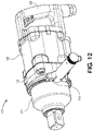
- the power tool assembly 130 includes a power tool 120 including a housing 124 having a barrel portion 122 as shown in FIG. 12 .
- the housing 124 also includes a primary handle 126 configured to be grasped by an operator when using the power tool assembly 130.
- the primary handle 126 may be used by the operator to pick up the power tool assembly 130, move it and guide it onto a workpiece.
- the primary handle 126 allows the operator to impart force to hold the power tool assembly 130 against the workpiece.
- the power tool assembly 130 includes an auxiliary handle assembly 100.
- the auxiliary handle assembly 100 allows the operator to resist the torque output of the power tool assembly 130 in high torque operations. As shown more specifically in FIGS. 12 , 17 and 18 , the auxiliary handle assembly 130 is coupled to the barrel 122.
- Other configurations of the power tool assembly 130 may include an auxiliary handle assembly 100 that is coupled to the power tool 120 instead of the barrel 122.
- the auxiliary handle assembly 100 includes a handle base 102, a strap 112, a locking lever 113, a release lever 101 and an adjusting knob 114.
- the handle base 102 extends radially from the strap 112 at an angle of approximately ninety degrees (90°).
- the auxiliary handle assembly 100 may connect the handle base 102 with the strap 112 at an angle other than ninety degrees (90°).
- the handle base 102 may include a features such as grooves or splines (not shown) formed in its surface to improve the grip of an operator. These features, may, for example, be formed using a knurling process. Examples of knurling that may be used in the handle base 102 to increase the improve the grip between the operator's hand and the auxiliary handle assembly 100 include, but are not limited to, linear or straight knurling, diagonal knurling, and diamond knurling. Additionally or alternatively, the surface of the auxiliary handle assembly 100 may be rubberized (e.g., include surface tubing or another type of elastomer sleeve to improve the grip of the operator's hand and the handle base 102.
- knurling that may be used in the handle base 102 to increase the improve the grip between the operator's hand and the auxiliary handle assembly 100 include, but are not limited to, linear or straight knurling, diagonal knurling, and diamond knurling.
- the auxiliary handle assembly 100 includes a handle base 102 having a chamber 118.
- the chamber 118 houses a yoke 115, an over-center linkage assembly 116 having a linking arm 111 and a spindle 109, a release lever 101, and an adjusting knob 114 coupled to the end of the handle base 102 opposite to the a strap 112.
- the strap 112 may be a generally a continuous circular member that comprises a first end 132 and a second end 134 coupled to the handle base 102.
- the strap may not be a continuous member and have an opening around the periphery of the strap, having the strap 112 be used as clamping arms, for example, as shown in FIGS. 13 through 18 .
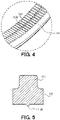
- the strap 112 includes a straight-cut transverse row of teeth 112A around the inside diameter of the strap that digs into the contours of the barrel portion 122 of the power tool 120 and prevents the strap from slipping rotationally around the barrel portion 122 when the auxiliary handle is in a locked position.
- the strap 112 also includes at least one lateral tooth 112B parallel to the transverse row of teeth 112A through the center of the strap 112.
- the at least one lateral tooth 112B digs into the contours of the barrel portion 122 of the power tool 120 and prevents the strap 112 from slipping axially off the barrel portion 122 when the power tool is in use.
- FIG. 5 illustrates a cross-sectional view of the strap 112 having the at least one lateral tooth 112B and a ridge-line support 136.
- the ridge-line support 136 increases the rigidity and strength and reduces the elasticity of strap 112.
- the ridge line support prevents rocking between the strap 112 and the power tool 120 when the handle base 102 is pushed towards the front of the power tool 120 when the power tool assembly 130 is in use.
- This ridge-line support is not limiting and some embodiments of the present disclosure may be designed without the ridge line support.
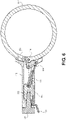
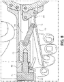
- FIGS. 6 through 9 show a cross-sectional view of the handle base 102 of the auxiliary handle 100.
- the locking lever 113 is rotationally connected to the spindle 109 and linking arm 111 by cylindrical pins 104.
- the spindle 109 is attached to the second end of the strap 134 by cylindrical pin 107, causing the second end of the strap 134 to rotate about this connection.
- the first end of the strap 132 is fixedly connected to the handle base 102.
- the locking lever 113 rotates the spindle 109 around its anchor point and closes the opening of the strap between the first end 132 and second end 134. By closing the opening of the strap, the internal diameter of the strap is reduced.
- the strap 112 When the strap 112 is in its resting state and wrapped around a barrel portion 122 of power tool 120 or another object that has a similar or equivalent diameter such as the strap 112, the strap can slide along the barrel portion 122 to a desired position along its longitudinal axis. As a user actuates the locking lever 113, causing the strap 112 to lock around the barrel portion 122, the internal diameter of the strap is closed and reaches the boundary of the outside diameter of the barrel portion 122. As the strap's diameter cannot be reduced further, any additional force by the user to the locking lever is translated into clamping force.
- the adjusting knob 114 allows fine adjustments to the angle of the locking lever 113 when the strap 112 is in a resting state.
- the adjusting knob 114 may be threaded into the yoke 115 and used to move the yoke 115 along the longitudinal axis of chamber 118 within handle base 102.
- the linking arm 111 is attached to the yoke 115 at a first end by cylindrical pin 105 and to the locking lever 113 by cylindrical pin 104.
- the cylindrical pins allow the linkage to move along the plane equivalent to the plane of movement of the locking lever 113.
- the threaded interface between the adjusting knob 114 and the yoke 115 forces the yoke 115 to axially move back and forth along the handle base chamber 118.
- the movement of the yoke 115 respectively moves the linking arm 111 back and forth, rotating the locking lever 113 about its pinned connection to the spindle 109 and changing the angle of the locking lever 113 with respect to the handle base 102.
- the angle between the locking lever 113 and the handle base 102 is increased.
- the angle between the locking lever 113 and the handle base 102 is decreased.
- the auxiliary handle assembly 100 is locked using the over-center linkage assembly 116.
- a four-bar mechanism comprised of bar A-B, bar B-C, bar C-D and bar D-A, magnifies the force input to the locking lever 113 at point F. This magnification of the input force is achieved when a large angular movement of the locking lever 113 results in a small movement of the second end of the strap 134. For example, with a ratio of 100:1, for every 1.0 degree of handle movement, the second end of the strap 134 moves and closes tightens the strap 112 by 0.01 degrees. An input force of 100 lbs. on the locking lever 113 at point F results in 10,000 lbs. of output force at the strap 112 at point E. This ratio varies throughout the limits of angular movement of the mechanism and is not intended to limit the present disclosure.
- the over-center linkage assembly 116 is represented by the three points of relational motion B, C, and D in FIG. 10 .
- points B, C, and D create a "V" shape.
- the locking lever 113 is closed as shown in FIG. 9 , the "V" shape formed by points B, C, and D is flattened until the three points are colinear.
- the position of the locking lever 113 where points B, C, and D are in alignment is the point of maximum mechanical advantage, resulting in the maximum clamp force exerted by the strap 112 unto the barrel portion 122, and will be referred to as the dead-center state or "clamping stage".
- the locking state achieved by the over-center linkage assembly can be overcome by acting on one of the three points that make up the over-center linkage, B, C, and D by moving the points back into a dead-center state and returning to the original "V" shape obtained when the auxiliary handle assembly 100 is in a resting position. This may be achieved by pushing directly on point C, or by applying a force to bar B-F in a direction opposite to the input force applied to locking lever 113 at point F.
- a release lever 101 is in contact with locking lever 113 when the locking lever 113 is actuated. When actuating release lever 101, point C in the locking lever 113 is pushed past the locking stage and the clamping stage, returning the locking lever to its resting state and releasing the clamping force exerted by strap 112.
- the lateral distance between points A and D are adjustable. Changing the distance between A and D changes the position of point B when the mechanism in in the clamping stage due to the constant distance between points A and B and the variable angle between bars A-B and A-D (which is affected by the distance between points A and D). Adjusting the position of point B sets a starting position for the second end of the strap 134 at point E, affecting the output clamping force of strap 112. This allows the auxiliary handle assembly to provide the necessary clamping force on working tools with a wide range of diameters, tolerances, and shapes to operate in low-torque and high-torque applications.
- an auxiliary handle assembly 200 comprises a first clamping arm 232, a second clamping arm 234, a handle base 202, a locking lever 213, and an adjusting knob 214.
- First clamping arm 232 and second clamping arm 234 form an opening diametrically opposed to the handle base 202 when the auxiliary handle assembly is in a resting position.
- locking lever 213 When a user actuates locking lever 213, the opening formed by first clamping arm 232 and second clamping arm 234 is closed.
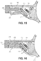
- FIGS. 15 and 16 show a cross-sectional view of the example embodiment shown in FIGS. 13 and 14 .
- the auxiliary handle assembly 200 includes the handle base 202 having a chamber 218.
- Chamber 218 houses a yoke 215, a linkage assembly 216 having a linking arm 211 and a spindle 209, a biasing member 201, and an adjusting knob 214 coupled to the end of the handle base 202 opposite to the first and second clamping arms 232 and 234.
- the first and second clamping arms 232 and 234 form a generally circular shape. However, in other embodiments, the clamping arms 232 and 234 may form a squared shape, a rectangular shape, an oval shape, an irregular shape, and so forth.
- a release lever is not needed, and the auxiliary handle assembly uses a biasing member 201 to release the linkage assembly 216 from its actuated position.
- Biasing member 201 may push the spindle 209 in a direction opposite to the input force applied to the locking lever 213.
- Biasing members may include but are not limited to tension springs, torsion springs, compression springs, leaf springs, and so forth.
- the auxiliary handle assembly 100 described in the present disclosure accommodates various barrel sizes and thus may be adapted for use on power tool assemblies having various power tool sizes.
- the strap 112 may be designed with a specific diameter that can be used on power tools with similar barrel diameters but may be interchanged with a strap with a different length or diameter for product models having a barrel diameter outside of the original adjustability range of the strap 112.
- the auxiliary handle assembly 100 used in power tool assembly 130 does not require additional tools to operate (e.g., wrenches, hex-keys, etc.), allowing the user to completely rotate the auxiliary handle assembly 100 by three-hundred-and-sixty degrees (360°) about the barrel portion 122 and lock the auxiliary handle assembly 100 into any angular position around the power tool 120 in a one-handed operation. This keeps the second hand of the user free to hold the primary handle 126 and support the weight of the power tool assembly 130 during use of the power tool 120 and during repositioning of the auxiliary handle assembly 100.
- additional tools to operate e.g., wrenches, hex-keys, etc.
Landscapes
- Engineering & Computer Science (AREA)
- Mechanical Engineering (AREA)
- Portable Power Tools In General (AREA)
Applications Claiming Priority (1)
| Application Number | Priority Date | Filing Date | Title |
|---|---|---|---|
| US17/150,085 US11453111B2 (en) | 2021-01-15 | 2021-01-15 | Auxiliary handle for a power tool |
Publications (1)
| Publication Number | Publication Date |
|---|---|
| EP4029655A1 true EP4029655A1 (de) | 2022-07-20 |
Family
ID=79283196
Family Applications (1)
| Application Number | Title | Priority Date | Filing Date |
|---|---|---|---|
| EP22150114.1A Withdrawn EP4029655A1 (de) | 2021-01-15 | 2022-01-04 | Zusatzhandgriff für ein elektrowerkzeug |
Country Status (3)
| Country | Link |
|---|---|
| US (1) | US11453111B2 (de) |
| EP (1) | EP4029655A1 (de) |
| CN (1) | CN114762969A (de) |
Citations (1)
| Publication number | Priority date | Publication date | Assignee | Title |
|---|---|---|---|---|
| US20060117579A1 (en) * | 1998-08-14 | 2006-06-08 | Zeiler Jeffrey M | Movable handle for a power tool |
Family Cites Families (15)
| Publication number | Priority date | Publication date | Assignee | Title |
|---|---|---|---|---|
| US3253850A (en) * | 1964-03-13 | 1966-05-31 | Alvin L Trusty | Quick releasable carrying device |
| US3585704A (en) * | 1969-05-19 | 1971-06-22 | John A Schroeder | Clamping device |
| US5351585A (en) * | 1993-08-11 | 1994-10-04 | Petersen Manufacturing Co. Inc. | Large capacity locking pliers |
| US5460461A (en) * | 1994-04-22 | 1995-10-24 | Mcgrath; Jim E. | Manual concrete screed handle |
| US6079639A (en) * | 1998-09-08 | 2000-06-27 | Barbato; Scott M. | Auxiliary handle with latching trigger for power washer pressure gun |
| FR2898032B1 (fr) * | 2006-03-06 | 2008-04-18 | Seb Sa | Dispositif de prehension amovible avec moyens d'ouverture des organes formant pince |
| US20070209162A1 (en) * | 2006-03-09 | 2007-09-13 | Mcroberts Jason | Auxiliary handle for reciprocating saw |
| US8328170B2 (en) * | 2009-06-19 | 2012-12-11 | Toyota Motor Engineering & Manufacturing North America , Inc. | Clamping apparatus |
| DE102009027570A1 (de) * | 2009-07-09 | 2011-01-13 | Robert Bosch Gmbh | Vorrichtung zum Positionieren und Befestigen einer Einrichtung, insbesondere eines Handgriffs an einem Elektrowerkzeug |
| US9550278B2 (en) * | 2011-08-10 | 2017-01-24 | Bosch Automotive Service Solutions Inc. | Tire beading locking tool and method for making same |
| JP5997660B2 (ja) * | 2013-05-29 | 2016-09-28 | 株式会社マキタ | 補助ハンドルおよび補助ハンドルを備えた往復動式作業工具 |
| US9205540B2 (en) * | 2013-11-08 | 2015-12-08 | Chao-Ching Lin | One-way drive strap wrench |
| EP3034245A1 (de) * | 2014-12-19 | 2016-06-22 | HILTI Aktiengesellschaft | Zusatzhandgriff |
| US10112287B2 (en) * | 2015-07-22 | 2018-10-30 | Patrick Gallagher | Tube clamping hand tool |
| US20170280940A1 (en) * | 2016-03-31 | 2017-10-05 | Justin Quinn | Culinary vessels with quick release detachable handles |
-
2021
- 2021-01-15 US US17/150,085 patent/US11453111B2/en active Active
-
2022
- 2022-01-04 EP EP22150114.1A patent/EP4029655A1/de not_active Withdrawn
- 2022-01-14 CN CN202210044919.5A patent/CN114762969A/zh active Pending
Patent Citations (1)
| Publication number | Priority date | Publication date | Assignee | Title |
|---|---|---|---|---|
| US20060117579A1 (en) * | 1998-08-14 | 2006-06-08 | Zeiler Jeffrey M | Movable handle for a power tool |
Also Published As
| Publication number | Publication date |
|---|---|
| US11453111B2 (en) | 2022-09-27 |
| CN114762969A (zh) | 2022-07-19 |
| US20220226980A1 (en) | 2022-07-21 |
Similar Documents
| Publication | Publication Date | Title |
|---|---|---|
| US8056451B2 (en) | Locking pliers | |
| US7861622B2 (en) | Locking pliers | |
| US5941142A (en) | Ratcheting adjustable jaw wrench and method of use | |
| WO2019051491A1 (en) | LOCKING SECTIONS WITH MOBILE JAW SECTION INCREASING TORQUE | |
| US7434498B2 (en) | Toggle-locking tool | |
| US20250229398A1 (en) | Multi-tool device | |
| US20090272236A1 (en) | Ratchetable open-ended wrench | |
| EP1306170A2 (de) | Drehmomentschlüssel | |
| US3590669A (en) | Pliers with adjustable toggle lock | |
| US20250262722A1 (en) | Locking pliers and other gripping tools | |
| US20200282544A1 (en) | Hand tool device | |
| US11453111B2 (en) | Auxiliary handle for a power tool | |
| US7347125B1 (en) | Automatic adjustable head wrench | |
| US5323674A (en) | Cordless drive power driven accessory clamp | |
| US20240100659A1 (en) | Wrenches | |
| US6679143B2 (en) | Manually operated impact tool | |
| AU2023248188B2 (en) | Handle and tool with integrated handle mount | |
| US7219583B1 (en) | Pneumatic screwdriver having an adjustable clockwise torque and a maximum counterclockwise torque | |
| US20060174732A1 (en) | Adjustable wrench with two movable jaws | |
| HK40056546A (en) | Direction selector mechanism for a power tool |
Legal Events
| Date | Code | Title | Description |
|---|---|---|---|
| PUAI | Public reference made under article 153(3) epc to a published international application that has entered the european phase |
Free format text: ORIGINAL CODE: 0009012 |
|
| STAA | Information on the status of an ep patent application or granted ep patent |
Free format text: STATUS: REQUEST FOR EXAMINATION WAS MADE |
|
| 17P | Request for examination filed |
Effective date: 20220104 |
|
| AK | Designated contracting states |
Kind code of ref document: A1 Designated state(s): AL AT BE BG CH CY CZ DE DK EE ES FI FR GB GR HR HU IE IS IT LI LT LU LV MC MK MT NL NO PL PT RO RS SE SI SK SM TR |
|
| GRAP | Despatch of communication of intention to grant a patent |
Free format text: ORIGINAL CODE: EPIDOSNIGR1 |
|
| STAA | Information on the status of an ep patent application or granted ep patent |
Free format text: STATUS: GRANT OF PATENT IS INTENDED |
|
| INTG | Intention to grant announced |
Effective date: 20240528 |
|
| STAA | Information on the status of an ep patent application or granted ep patent |
Free format text: STATUS: THE APPLICATION IS DEEMED TO BE WITHDRAWN |
|
| 18D | Application deemed to be withdrawn |
Effective date: 20241001 |