EP4029654A1 - High volume, low pressure, inflator - Google Patents
High volume, low pressure, inflator Download PDFInfo
- Publication number
- EP4029654A1 EP4029654A1 EP21214191.5A EP21214191A EP4029654A1 EP 4029654 A1 EP4029654 A1 EP 4029654A1 EP 21214191 A EP21214191 A EP 21214191A EP 4029654 A1 EP4029654 A1 EP 4029654A1
- Authority
- EP
- European Patent Office
- Prior art keywords
- inflator
- housing portion
- air
- fan housing
- air outlet
- Prior art date
- Legal status (The legal status is an assumption and is not a legal conclusion. Google has not performed a legal analysis and makes no representation as to the accuracy of the status listed.)
- Granted
Links
Images






Classifications
-
- F—MECHANICAL ENGINEERING; LIGHTING; HEATING; WEAPONS; BLASTING
- F04—POSITIVE - DISPLACEMENT MACHINES FOR LIQUIDS; PUMPS FOR LIQUIDS OR ELASTIC FLUIDS
- F04B—POSITIVE-DISPLACEMENT MACHINES FOR LIQUIDS; PUMPS
- F04B39/00—Component parts, details, or accessories, of pumps or pumping systems specially adapted for elastic fluids, not otherwise provided for in, or of interest apart from, groups F04B25/00 - F04B37/00
- F04B39/12—Casings; Cylinders; Cylinder heads; Fluid connections
-
- F—MECHANICAL ENGINEERING; LIGHTING; HEATING; WEAPONS; BLASTING
- F04—POSITIVE - DISPLACEMENT MACHINES FOR LIQUIDS; PUMPS FOR LIQUIDS OR ELASTIC FLUIDS
- F04B—POSITIVE-DISPLACEMENT MACHINES FOR LIQUIDS; PUMPS
- F04B35/00—Piston pumps specially adapted for elastic fluids and characterised by the driving means to their working members, or by combination with, or adaptation to, specific driving engines or motors, not otherwise provided for
- F04B35/04—Piston pumps specially adapted for elastic fluids and characterised by the driving means to their working members, or by combination with, or adaptation to, specific driving engines or motors, not otherwise provided for the means being electric
-
- B—PERFORMING OPERATIONS; TRANSPORTING
- B25—HAND TOOLS; PORTABLE POWER-DRIVEN TOOLS; MANIPULATORS
- B25F—COMBINATION OR MULTI-PURPOSE TOOLS NOT OTHERWISE PROVIDED FOR; DETAILS OR COMPONENTS OF PORTABLE POWER-DRIVEN TOOLS NOT PARTICULARLY RELATED TO THE OPERATIONS PERFORMED AND NOT OTHERWISE PROVIDED FOR
- B25F5/00—Details or components of portable power-driven tools not particularly related to the operations performed and not otherwise provided for
- B25F5/02—Construction of casings, bodies or handles
-
- F—MECHANICAL ENGINEERING; LIGHTING; HEATING; WEAPONS; BLASTING
- F04—POSITIVE - DISPLACEMENT MACHINES FOR LIQUIDS; PUMPS FOR LIQUIDS OR ELASTIC FLUIDS
- F04B—POSITIVE-DISPLACEMENT MACHINES FOR LIQUIDS; PUMPS
- F04B39/00—Component parts, details, or accessories, of pumps or pumping systems specially adapted for elastic fluids, not otherwise provided for in, or of interest apart from, groups F04B25/00 - F04B37/00
- F04B39/14—Provisions for readily assembling or disassembling
-
- F—MECHANICAL ENGINEERING; LIGHTING; HEATING; WEAPONS; BLASTING
- F04—POSITIVE - DISPLACEMENT MACHINES FOR LIQUIDS; PUMPS FOR LIQUIDS OR ELASTIC FLUIDS
- F04D—NON-POSITIVE-DISPLACEMENT PUMPS
- F04D25/00—Pumping installations or systems
- F04D25/02—Units comprising pumps and their driving means
- F04D25/06—Units comprising pumps and their driving means the pump being electrically driven
- F04D25/0673—Battery powered
-
- F—MECHANICAL ENGINEERING; LIGHTING; HEATING; WEAPONS; BLASTING
- F04—POSITIVE - DISPLACEMENT MACHINES FOR LIQUIDS; PUMPS FOR LIQUIDS OR ELASTIC FLUIDS
- F04D—NON-POSITIVE-DISPLACEMENT PUMPS
- F04D25/00—Pumping installations or systems
- F04D25/02—Units comprising pumps and their driving means
- F04D25/08—Units comprising pumps and their driving means the working fluid being air, e.g. for ventilation
- F04D25/084—Units comprising pumps and their driving means the working fluid being air, e.g. for ventilation hand fans
-
- F—MECHANICAL ENGINEERING; LIGHTING; HEATING; WEAPONS; BLASTING
- F04—POSITIVE - DISPLACEMENT MACHINES FOR LIQUIDS; PUMPS FOR LIQUIDS OR ELASTIC FLUIDS
- F04D—NON-POSITIVE-DISPLACEMENT PUMPS
- F04D29/00—Details, component parts, or accessories
- F04D29/60—Mounting; Assembling; Disassembling
- F04D29/62—Mounting; Assembling; Disassembling of radial or helico-centrifugal pumps
-
- B—PERFORMING OPERATIONS; TRANSPORTING
- B25—HAND TOOLS; PORTABLE POWER-DRIVEN TOOLS; MANIPULATORS
- B25F—COMBINATION OR MULTI-PURPOSE TOOLS NOT OTHERWISE PROVIDED FOR; DETAILS OR COMPONENTS OF PORTABLE POWER-DRIVEN TOOLS NOT PARTICULARLY RELATED TO THE OPERATIONS PERFORMED AND NOT OTHERWISE PROVIDED FOR
- B25F3/00—Associations of tools for different working operations with one portable power-drive means; Adapters therefor
-
- F—MECHANICAL ENGINEERING; LIGHTING; HEATING; WEAPONS; BLASTING
- F05—INDEXING SCHEMES RELATING TO ENGINES OR PUMPS IN VARIOUS SUBCLASSES OF CLASSES F01-F04
- F05D—INDEXING SCHEME FOR ASPECTS RELATING TO NON-POSITIVE-DISPLACEMENT MACHINES OR ENGINES, GAS-TURBINES OR JET-PROPULSION PLANTS
- F05D2230/00—Manufacture
- F05D2230/50—Building or constructing in particular ways
- F05D2230/52—Building or constructing in particular ways using existing or "off the shelf" parts, e.g. using standardized turbocharger elements
Definitions
- the present disclosure relates to an inflator.
- exemplary embodiments disclose a high flow, low pressure, inflator.
- aspects of the present disclosure relate to an exemplary embodiment of an inflator power tool.
- a first of the present invention provides a high-volume, low pressure, inflator according to Claim 1 of the appended claims.
- any feature, including any preferred or other optional feature, of any aspect or embodiment of the invention may be a feature, including a preferred or other optional feature, of any other aspect or embodiment of the invention.
- the first aspect of the invention provides a high-volume, low pressure, inflator, comprising: a housing; a handle formed by the housing; a motor housed in the housing; a trigger configured to activate the motor; an inlet having an inlet axis that is generally parallel or concentric with a longitudinal axis of the motor; an outlet which is transverse to the inlet; and a fan configured to draw air in through the inlet and blow air out through the outlet; wherein the inlet is generally transverse to the handle; and wherein the position of the outlet is rotatable relative to the handle.
- a high-volume, low pressure inflator that includes a housing; a handle formed by the housing; a motor housed in the housing; a trigger configured to activate the motor; an inlet having an inlet axis that is generally parallel or concentric with a longitudinal axis of the motor; an outlet which is transverse to the inlet; a fan configured to draw air in through the inlet and blow air out through the outlet.
- the inlet may be generally transverse to the handle.
- the position of the outlet may be rotatable relative to the handle.
- the outlet may be rotatable about a rotation axis.
- the rotation axis may be generally concentric or parallel to the longitudinal axis of the motor.
- the rotation axis may be generally transverse to the handle.
- an inflator including a tool base unit, the tool base unit comprising a handle, a motor and a trigger; and an inflator tool head removably attached to the tool base unit.
- the inflator tool head may include an air inlet, an air outlet and a fan configured to draw air in through the air inlet and blow air out through the air outlet.
- the inlet may be transverse to the outlet.
- the outlet may be rotatable with respect to the tool base unit while the inflator tool head is attached to the tool base unit.
- the inlet may be generally transverse to the handle.
- the inflator may further include an attachment holder configured to hold an inflator attachment.
- the attachment holder may be disposed on the inflator tool head.
- the inflator tool head may include a connection portion and a fan housing portion.
- the fan may be disposed in the fan housing portion.
- the fan housing portion may be rotatable with respect to the connection portion.
- the fan housing portion may include the air outlet.
- the fan housing portion may include the air inlet.
- the fan housing portion may be configured to be held in place in a variety of rotational positions with respect to the connection portion.
- the fan housing portion may be configured to be held in place by friction.
- the fan housing portion may be configured to be held in place by a biasing assembly.
- the fan housing portion may be configured to be held in place at plurality of distinct rotational positions.
- the plurality of distinct rotational positions may include at least four distinct rotational positions.
- a high-volume, low pressure inflator including a housing; a handle formed by the housing; a motor housed in the housing; a trigger configured to activate the motor; an inflator head portion; an inlet having an inlet axis that is generally parallel or concentric with a longitudinal axis of the motor; an outlet which is transverse to the inlet; a fan configured to draw air in through the inlet and blow air out through the outlet.
- the inlet may be generally transverse to the handle.
- the position of the outlet may be rotatable relative to the handle.
- the inflator head portion may include a connection portion and a fan housing portion.
- the fan may be disposed in the fan housing portion.
- the fan housing portion may include the outlet and is rotatable with respect to the connection portion.
- the outlet may be rotatable about a rotation axis.
- the rotation axis may be generally concentric or parallel to the longitudinal axis of the motor.
- the rotation axis may be generally transverse to the handle.
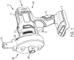
- Fig. 1 illustrates a first exemplary embodiment of inflator 10.
- the inflator 10 of the exemplary embodiment is a high volume, low pressure inflator of that provides a high volume of airflow for inflating air mattresses, rafts and other inflatable items.
- the inflator 10 includes a housing 11.
- the housing 11 forms a handle 12 and a motor housing portion 13.
- a motor is housed in the motor housing portion 13.
- the housing 11 also has a battery receiving portion 14 configured to receive a battery pack.
- the battery pack may be a power tool battery pack configured to power a variety of power tools such as drills, sanders and saws.
- the battery pack may be of the type shown in, for example, U.S. Patent No. 7,598,705 ; U.S. Patent No. 7,661,486 ; or U.S. Patent Application Publication No. 2018/0331335 .
- U.S. Patent No. 7,598,705 ; U.S. Patent No. 7,661,486 ; and U.S. Patent Application Publication No. 2018/0331335 are hereby incorporated by reference.
- the battery pack powers the inflator 10 and particularly the motor of the inflator 10.
- a user-actuatable trigger 15 is housed in the handle 12. The trigger 15 can be actuated to actuate the motor.
- the inflator 10 of the first exemplary embodiment includes a tool base unit 100 and an inflator tool head 200. As is shown in Fig. 2 of the present application, the inflator tool head 200 is removably attached to the tool base unit 100. Other tool heads such as a drill tool head, saw tool head, sander tool head and others may also be attached to the tool base unit 100 forming a multi-headed tool system.
- the tool base unit 100 may be of the same design as the tool base unit 100 show in U.S. Patent No. 9,956,677 , which is hereby incorporated by reference in its entirety and the tool base unit 100 of the present application may similarly accept the variety of tool heads as discussed in U.S. Patent No. 9,956,677 .
- U.S. Patent No. 9,421,682 and U.S. Patent No. 9,776,315 are other examples of multi-headed tool systems.
- U.S. Patent No. 9,421,682 and U.S. Patent No. 9,776,315 are hereby incorporated by reference in their entireties.
- the inflator head portion 200 includes a connection portion 210.
- the connection portion is configured to connect to the tool base unit and transfer power from the motor of the tool base unit 100 to the tool head portion.
- the inflator head 200 further includes a fan housing portion 220 which houses a fan (fan 60 in Figs. 17 and 18 is described further below). The fan draws air in through the inlet 240 and pushes air out through the air outlet 245. In this way, the inflator 10 can be used to inflate and deflate inflatable objects.
- Figs. 3 and 4 show an example of the inflator 10 inflating and deflating a mattress 500.
- the air outlet 245 is engaged with the mattress 500 and the air inlet 240 is directed towards ambient air. In this position, air is drawn in through the air inlet 240 and directed through the air outlet 245 to the mattress 500.
- Fig. 4 shows the inflator 10 in a position to deflate the mattress 500.
- the air inlet 240 is engaged with the mattress 500.
- the air outlet 245 is directed to ambient atmosphere. Accordingly, the inflator 10 draws air in from the mattress 500 through the air inlet 240 and blows it out of the air outlet 245. In this way, it deflates the mattress 500.
- the inflator 10 is shown inflating and deflating a mattress 500 in Figs. 3 and 4 , it is understood that the inflator 10 may similarly be used to inflate or deflate a variety of other inflatable products such as rafts, inter-tubes, beach balls and the like.
- Figs. 5 and 6 illustrate the inflator head 200 alone.
- Fig. 6 illustrates a portion of the connection section 210 that interfaces with the tool base unit 100.
- the connection section 210 includes an intermediate input member 215 which receives a rotary drive from the motor.
- the intermediate input member 215 engages with an intermediate output member which is driven by the motor. In this way, rotary drive from the motor in the tool base unit 100 is transferred to the inflator tool head 200.
- the air inlet 240 has an inlet axis that is generally parallel or concentric with a longitudinal axis of the motor.
- the air outlet 245 is transverse to the air inlet 240. Additionally, the air inlet 240 is generally transverse to the handle 12.
- Figs. 7-12 illustrate another exemplary embodiment of an inflator 101.
- the inflator 101 is the same as inflator 10 except with respect to the orientation of the air outlet 345.
- the tool base unit 100 is the same as in the inflator 10.
- the inflator tool head 300 is the same as the inflator tool head 200, except that the air outlet 345 of the inflator tool head 300 is disposed to direct air sideways/horizontal as opposed to upwards/vertical.
- Fig. 7 illustrates the inflator 101 in the assembled condition with the inflator tool head 300 attached to the tool base unit 100.
- the air outlet 345 is directed to the side. That is, if the tool base unit 100 is placed on a horizontal surface, the air outlet 345 is generally to the side rather than up or down. Put another way, the air outlet 345 is generally transverse to the handle 12.
- the air outlet 345 is also generally transverse to a longitudinal axis of the motor.
- the motor produces a rotary drive along the longitudinal axis of the motor.
- the longitudinal axis of the motor is generally parallel or concentric with a longitudinal axis of the motor housing 13 and is generally transverse to the handle 12.
- Fig. 8 illustrates the inflator 101 with the inflator tool head 300 removed.
- Fig. 9 illustrates the inflator 101 with the air outlet 345 engaged with the mattress 500 in order to inflate the mattress 500.
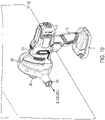
- Fig. 10 illustrates the inflator 101 with the air inlet 240 engaged with the mattress 500 in order to deflate the mattress 500.
- Figs. 11 and 12 are views of the inflator tool head 300 by itself.
- the first embodiment of the inflator 10 in Figs. 1-6 illustrates the air outlet 245 in a first, upward, direction.
- the second embodiment of the inflator 101 in Figs. 7-12 illustrates the air outlet 345 in a second, sideways, direction.
- the air outlet may also be radially located at various other directions. For example, the air outlet may be directed down instead of up.
- the air outlet 345 may be directed to the opposite side from that shown in Figs. 7-12 . Additionally, the air outlets 245, 345 may be directed at intermediate angled positions.
- Figs. 13-18 illustrate another exemplary embodiment of an inflator 102.
- Inflator 102 has the same base unit 100 as the inflators 10 and 101.
- Inflator 102 has an inflator tool head 400.
- the inflator tool head 400 is similar to the inflator tool heads 200 and 300.
- the inflator tool head 400 has a rotatable portion such that the air outlet 445 may be rotated 360 degrees to be pointed at various directions.
- the outlet 445 is pointed straight up.
- the outlet 445 has been rotated to be at an angle between horizontal and vertical, roughly 45 degrees from horizontal or within a range of 30 to 60 degrees from vertical or horizontal.
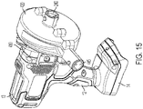
- Fig. 15 illustrates the outlet 445 pointing to the side/horizontal and
- Fig. 16 illustrates the outlet pointing downwardly.
- the outlet 445 may be positioned at any angle along about the rotational axis.
- Figs. 17 and 18 illustrate the rotatable structure of the inflator tool head 400.
- the inflator tool head 400 has a fan housing portion 420 that is made as a separate part and is rotatable with respect to the connection portion 410. This is in contrast to the inflator tool heads 200 and 300, in which the connection portion 210 and the fan housing portion 220 are made of a single piece.
- connection portion 410 has a projection 411 and the fan housing portion 420 has a groove 421.
- the projection 411 engages with the groove 421 to rotatably connect the fan housing portion 420 and the connection portion 410.
- the fan connection portion 410 has an abutting wall 412 and the fan housing portion has an abutting wall 422.
- the connection portion abutting wall 412 abuts the housing portion abutting wall 422 providing stability to the connection. In some embodiments, these abutting walls 412, 422 provide friction to maintain the relative rotational location of the fan housing portion 420 to the fan connection portion 410.
- the user can then rotate the fan housing portion 420 by applying pressure to overcome the friction. In this way, the user can change the angular position of the air outlet 445 among the various rotational locations.
- the amount of friction can be provided by the dimensioning of the connection and fan housing portions 410 and 420; the materials of the connection and fan housing portions 410 and 420 or the abutting walls 412, 422; surface treatments of the connection and fan housing portions 410 and 420 or the abutting walls 412, 422; other methods for increasing or controlling friction or a combination of the same.
- the abutting walls 412, 422 may be made to tightly abut one another in order to increase friction.
- facing surfaces of the abutting walls 412, 422 may be coated with a high friction material such as rubber in order to increase the friction between the connection housing 410 and fan housing portions 420.
- the fan housing portion includes both the air inlet 240 and the air outlet 445.
- the air inlet 240 is at or on a rotational axis of the fan housing portion 420. Accordingly, although the air inlet 240 of the exemplary embodiment rotates along with the fan housing portion 420, the axis of the air inlet 240 changes none if on the rotational axis or only slightly if slightly off of the rotational axis. Thus, the overall position of the air inlet 240 is relatively the same in all positions of the fan housing portion 420. In other exemplary embodiments, the air inlet 240 may be disposed offset from the rotational axis of the fan housing portion 420 such that the position of the axis of the air inlet 240 also changes when the fan housing portion 420 rotates.
- the air outlet 445 is at an outer circumference of the fan housing portion 420. Additionally, the air outlet 445 has an axis that is transverse to a rotational axis of the fan housing portion 240. Accordingly, the position of the air outlet 445 changes along with the rotational position of the fan housing portion 240.
- the rotational position of the fan housing portion 420 may alternatively or additionally be provided by a biasing assembly.
- the ball 430 contacts the fan housing portion 420 to maintain the fan housing portion 420 in a rotational location.
- a user may provide a force to overcome the force provided by the ball 430 to move from the particular rotational location to another rotational location.
- the fan housing portion 420 may include recesses at particular locations that receive the ball 430.
- the recesses 435 are located at particular specific locations which may be useful to a user. For example, the recesses 435 may be placed at four locations about the fan housing portion 420, ninety-degrees apart.
- the fan housing portion 420 may be specifically set at those four specific and discrete locations, such as up, down, left and right.
- the biasing assembly may be different than a ball biased by a spring.
- another biasing member may be used instead of a spring and instead of a ball there may be another type of projection or rigid element that engages with the recesses 435.
- the biasing member and rigid element may also be one piece so that the biasing assembly is a one piece member that serves the same function. For example, this could be a compressible projection.
- the position of the air outlet 445 is rotatable relative to the handle 12 and is rotatable about a rotation axis.
- the rotation axis may be generally concentric or parallel to the longitudinal axis of the moto and generally transverse to the handle 12.
- Figs. 17 and 18 provide cross-sectional views of the inflator head 400 so that internals of the inflator head 400 can be seen.
- the inflator head 400 includes a drive connector 70.
- the drive connector 70 receives rotational motion from the motor.
- a spindle 75 is driven through the drive connector 70 and is connected to a fan 60. Accordingly, the motor drives the fan 60.
- Internals of the inflator heads 200 and 300 are the same as that for the inflator head 400 except that the inflator heads 200 and 300 do not include the rotational features of inflator head 400. Accordingly, inflator heads 200 and 300 similarly include drive connector 70, spindle 75 and fan 60.
- Groove 421, projection 411 and abutting walls 412, 422 and the biasing assembly may be removed in inflator heads 200 and 300.
- one or more of these components may also be maintained in the inflator heads 200, 300 in order to provide rigidity.
- the structure of abutting walls 412, 422 may be included in the inflator heads 200, 300 in order to provide rigidity for the inflator heads even if they lack a rotation feature. In that case, the abutting walls 412, 422 may be joined or formed as one integral part.
- Figs. 19 and 20 illustrate inflator attachment holders 500.
- the inflator attachment holders 500 are attached to either side of the connection portion 410.
- the inflator attachment holders 500 hold inflator attachments 510 which can be slid over the air inlet or air outlet so as to interface with various inflatables.
- Fig. 19 illustrates the attachment holders 500 holding the inflator attachments 510 and
- Fig. 20 illustrates the attachment holders 500 when empty.
- the inflators 10, 101 and 102 are formed by a tool base unit and a removable inflator tool head unit.
- the inflators may also be made as a stand-alone tool where the inflator tool head is integrated with a base unit in a fixed manner rather than being separable.
Landscapes
- Engineering & Computer Science (AREA)
- Mechanical Engineering (AREA)
- General Engineering & Computer Science (AREA)
- Portable Nailing Machines And Staplers (AREA)
- Portable Power Tools In General (AREA)
Abstract
Description
- The present disclosure relates to an inflator. In particular, exemplary embodiments disclose a high flow, low pressure, inflator.
- Aspects of the present disclosure relate to an exemplary embodiment of an inflator power tool.
- A first of the present invention provides a high-volume, low pressure, inflator according to Claim 1 of the appended claims.
- Preferred, and other optional, features of the invention are described and defined in the dependent claims.
- It is to be understood that any feature, including any preferred or other optional feature, of any aspect or embodiment of the invention may be a feature, including a preferred or other optional feature, of any other aspect or embodiment of the invention.
- Accordingly, the first aspect of the invention provides a high-volume, low pressure, inflator, comprising: a housing; a handle formed by the housing; a motor housed in the housing; a trigger configured to activate the motor; an inlet having an inlet axis that is generally parallel or concentric with a longitudinal axis of the motor; an outlet which is transverse to the inlet; and a fan configured to draw air in through the inlet and blow air out through the outlet; wherein the inlet is generally transverse to the handle; and wherein the position of the outlet is rotatable relative to the handle.
- (By "generally concentric" herein is meant "generally coaxial", i.e. by "concentric" is meant "coaxial", herein.)
- According to another aspect of the invention, there is a high-volume, low pressure inflator that includes a housing; a handle formed by the housing; a motor housed in the housing; a trigger configured to activate the motor; an inlet having an inlet axis that is generally parallel or concentric with a longitudinal axis of the motor; an outlet which is transverse to the inlet; a fan configured to draw air in through the inlet and blow air out through the outlet.
- The inlet may be generally transverse to the handle.
- The position of the outlet may be rotatable relative to the handle.
- The outlet may be rotatable about a rotation axis.
- The rotation axis may be generally concentric or parallel to the longitudinal axis of the motor.
- The rotation axis may be generally transverse to the handle.
- According to another aspect of the invention, there is an inflator, the inflator including a tool base unit, the tool base unit comprising a handle, a motor and a trigger; and an inflator tool head removably attached to the tool base unit.
- The inflator tool head may include an air inlet, an air outlet and a fan configured to draw air in through the air inlet and blow air out through the air outlet.
- The inlet may be transverse to the outlet.
- The outlet may be rotatable with respect to the tool base unit while the inflator tool head is attached to the tool base unit.
- The inlet may be generally transverse to the handle.
- The inflator may further include an attachment holder configured to hold an inflator attachment.
- The attachment holder may be disposed on the inflator tool head.
- The inflator tool head may include a connection portion and a fan housing portion.
- The fan may be disposed in the fan housing portion.
- The fan housing portion may be rotatable with respect to the connection portion.
- The fan housing portion may include the air outlet.
- The fan housing portion may include the air inlet.
- The fan housing portion may be configured to be held in place in a variety of rotational positions with respect to the connection portion.
- The fan housing portion may be configured to be held in place by friction.
- The fan housing portion may be configured to be held in place by a biasing assembly.
- The fan housing portion may be configured to be held in place at plurality of distinct rotational positions.
- The plurality of distinct rotational positions may include at least four distinct rotational positions.
- The connection portion may house a connector which receives drive from the motor.
- According to another aspect of the invention, there is a high-volume, low pressure inflator, the inflator including a housing; a handle formed by the housing; a motor housed in the housing; a trigger configured to activate the motor; an inflator head portion; an inlet having an inlet axis that is generally parallel or concentric with a longitudinal axis of the motor; an outlet which is transverse to the inlet; a fan configured to draw air in through the inlet and blow air out through the outlet.
- The inlet may be generally transverse to the handle.
- The position of the outlet may be rotatable relative to the handle.
- The inflator head portion may include a connection portion and a fan housing portion.
- The fan may be disposed in the fan housing portion.
- The fan housing portion may include the outlet and is rotatable with respect to the connection portion.
- The outlet may be rotatable about a rotation axis.
- The rotation axis may be generally concentric or parallel to the longitudinal axis of the motor.
- The rotation axis may be generally transverse to the handle.
- These and other aspects of various embodiments of the present invention, as well as the methods of operation and functions of the related elements of structure and the combination of parts and economies of manufacture, will become more apparent upon consideration of the following description and the appended claims with reference to the accompanying drawings, all of which form a part of this specification, wherein like reference numerals designate corresponding parts in the various figures. In embodiments of the invention, the structural components illustrated herein are drawn to scale. It is to be expressly understood, however, that the drawings are for the purpose of illustration and description only and are not intended as a definition of the limits of the invention. In addition, it should be appreciated that structural features shown or described in any one embodiment herein can be used in other embodiments as well. As used in the specification and in the claims, the singular form of "a", "an", and "the" include plural referents unless the context clearly dictates otherwise.
- For a better understanding of exemplary embodiments of the present invention as well as other objects and further features thereof, reference is made to the following description which is to be used in conjunction with the accompanying drawings, where:
-
FIG. 1 is a perspective view of an inflator according to a first exemplary embodiment of the present invention; -
FIG. 2 is a perspective view of the exemplary embodiment of the inflator with the inflator tool head removed from the tool base unit; -
FIG. 3 is a perspective view of the inflator inflating a mattress; -
FIG. 4 is a perspective view of the inflator deflating the mattress; -
FIG. 5 is a perspective view the inflator tool head of the exemplary embodiment of the inflator; -
FIG. 6 is another perspective view the inflator tool head of the exemplary embodiment of the inflator; -
FIG. 7 is a perspective view of an inflator according to a second exemplary embodiment of the present invention; -
FIG. 8 is a perspective view of the second exemplary embodiment of the inflator with the inflator tool head removed from the tool base unit; -
FIG. 9 is a perspective view of the second exemplary embodiment of the inflator inflating a mattress; -
FIG. 10 is a perspective view of the inflator deflating the mattress; -
FIG. 11 is a perspective view the inflator tool head of the exemplary embodiment of the inflator; -
FIG. 12 is another perspective view the inflator tool head of the exemplary embodiment of the inflator; -
FIG. 13 is a perspective view of an inflator according to a third exemplary embodiment of the invention; -
FIG. 14 is another perspective view of the inflator according to the third exemplary embodiment; -
FIG. 15 is another perspective view of the inflator according to the third exemplary embodiment; -
FIG. 16 is another perspective view of the inflator according to the third exemplary embodiment; -
FIG. 17 is a close-up cut-away view of the inflator according to the third exemplary embodiment; -
FIG. 18 is another close-up cut-away view of an inflator according to the third exemplary embodiment; -
FIG. 19 is a perspective view of the inflator with attachment holders; and -
FIG. 20 is a close-up perspective view of the inflator with attachment holders. -
Fig. 1 illustrates a first exemplary embodiment ofinflator 10. Theinflator 10 of the exemplary embodiment is a high volume, low pressure inflator of that provides a high volume of airflow for inflating air mattresses, rafts and other inflatable items. As shown inFig. 1 , theinflator 10 includes ahousing 11. Thehousing 11 forms ahandle 12 and amotor housing portion 13. A motor is housed in themotor housing portion 13. There may be a transmission connected to the motor. Thehousing 11 also has abattery receiving portion 14 configured to receive a battery pack. In this case, the battery pack may be a power tool battery pack configured to power a variety of power tools such as drills, sanders and saws. The battery pack may be of the type shown in, for example,U.S. Patent No. 7,598,705 ;U.S. Patent No. 7,661,486 ; orU.S. Patent Application Publication No. 2018/0331335 .U.S. Patent No. 7,598,705 ;U.S. Patent No. 7,661,486 ; andU.S. Patent Application Publication No. 2018/0331335 are hereby incorporated by reference. The battery pack powers the inflator 10 and particularly the motor of theinflator 10. A user-actuatable trigger 15 is housed in thehandle 12. Thetrigger 15 can be actuated to actuate the motor. - The
inflator 10 of the first exemplary embodiment includes atool base unit 100 and aninflator tool head 200. As is shown inFig. 2 of the present application, theinflator tool head 200 is removably attached to thetool base unit 100. Other tool heads such as a drill tool head, saw tool head, sander tool head and others may also be attached to thetool base unit 100 forming a multi-headed tool system. Thetool base unit 100 may be of the same design as thetool base unit 100 show inU.S. Patent No. 9,956,677 tool base unit 100 of the present application may similarly accept the variety of tool heads as discussed inU.S. Patent No. 9,956,677 -
U.S. Patent No. 9,421,682 U.S. Patent No. 9,776,315 U.S. Patent No. 9,421,682 U.S. Patent No. 9,776,315 - The
inflator head portion 200 includes aconnection portion 210. The connection portion is configured to connect to the tool base unit and transfer power from the motor of thetool base unit 100 to the tool head portion. Theinflator head 200 further includes afan housing portion 220 which houses a fan (fan 60 inFigs. 17 and 18 is described further below). The fan draws air in through theinlet 240 and pushes air out through theair outlet 245. In this way, the inflator 10 can be used to inflate and deflate inflatable objects. -
Figs. 3 and4 show an example of the inflator 10 inflating and deflating amattress 500. InFig. 3 , theair outlet 245 is engaged with themattress 500 and theair inlet 240 is directed towards ambient air. In this position, air is drawn in through theair inlet 240 and directed through theair outlet 245 to themattress 500. -
Fig. 4 shows the inflator 10 in a position to deflate themattress 500. InFig. 4 , theair inlet 240 is engaged with themattress 500. Theair outlet 245 is directed to ambient atmosphere. Accordingly, the inflator 10 draws air in from themattress 500 through theair inlet 240 and blows it out of theair outlet 245. In this way, it deflates themattress 500. Although the inflator 10 is shown inflating and deflating amattress 500 inFigs. 3 and4 , it is understood that the inflator 10 may similarly be used to inflate or deflate a variety of other inflatable products such as rafts, inter-tubes, beach balls and the like. -
Figs. 5 and 6 illustrate theinflator head 200 alone.Fig. 6 illustrates a portion of theconnection section 210 that interfaces with thetool base unit 100. As shown, theconnection section 210 includes an intermediate input member 215 which receives a rotary drive from the motor. In particular, the intermediate input member 215 engages with an intermediate output member which is driven by the motor. In this way, rotary drive from the motor in thetool base unit 100 is transferred to theinflator tool head 200. - As shown in
Figs. 1-6 , theair inlet 240 has an inlet axis that is generally parallel or concentric with a longitudinal axis of the motor. Theair outlet 245 is transverse to theair inlet 240. Additionally, theair inlet 240 is generally transverse to thehandle 12. -
Figs. 7-12 illustrate another exemplary embodiment of an inflator 101. The inflator 101 is the same asinflator 10 except with respect to the orientation of theair outlet 345. In particular, thetool base unit 100 is the same as in theinflator 10. Additionally, theinflator tool head 300 is the same as theinflator tool head 200, except that theair outlet 345 of theinflator tool head 300 is disposed to direct air sideways/horizontal as opposed to upwards/vertical. -
Fig. 7 illustrates the inflator 101 in the assembled condition with theinflator tool head 300 attached to thetool base unit 100. As shown inFig. 7 , when thetool head 300 is attached to thetool base unit 100, theair outlet 345 is directed to the side. That is, if thetool base unit 100 is placed on a horizontal surface, theair outlet 345 is generally to the side rather than up or down. Put another way, theair outlet 345 is generally transverse to thehandle 12. Theair outlet 345 is also generally transverse to a longitudinal axis of the motor. The motor produces a rotary drive along the longitudinal axis of the motor. The longitudinal axis of the motor is generally parallel or concentric with a longitudinal axis of themotor housing 13 and is generally transverse to thehandle 12. -
Fig. 8 illustrates the inflator 101 with theinflator tool head 300 removed.Fig. 9 illustrates the inflator 101 with theair outlet 345 engaged with themattress 500 in order to inflate themattress 500.Fig. 10 illustrates the inflator 101 with theair inlet 240 engaged with themattress 500 in order to deflate themattress 500.Figs. 11 and12 are views of theinflator tool head 300 by itself. - The first embodiment of the inflator 10 in
Figs. 1-6 illustrates theair outlet 245 in a first, upward, direction. The second embodiment of the inflator 101 inFigs. 7-12 illustrates theair outlet 345 in a second, sideways, direction. The air outlet may also be radially located at various other directions. For example, the air outlet may be directed down instead of up. Theair outlet 345 may be directed to the opposite side from that shown inFigs. 7-12 . Additionally, theair outlets -
Figs. 13-18 illustrate another exemplary embodiment of an inflator 102. Inflator 102 has thesame base unit 100 as theinflators 10 and 101. Inflator 102 has an inflator tool head 400. The inflator tool head 400 is similar to the inflator tool heads 200 and 300. However, the inflator tool head 400 has a rotatable portion such that theair outlet 445 may be rotated 360 degrees to be pointed at various directions. For example, inFig. 13 , theoutlet 445 is pointed straight up. InFig. 14 , theoutlet 445 has been rotated to be at an angle between horizontal and vertical, roughly 45 degrees from horizontal or within a range of 30 to 60 degrees from vertical or horizontal.Fig. 15 illustrates theoutlet 445 pointing to the side/horizontal andFig. 16 illustrates the outlet pointing downwardly. Theoutlet 445 may be positioned at any angle along about the rotational axis. -
Figs. 17 and 18 illustrate the rotatable structure of the inflator tool head 400. As shown inFigs. 17 and 18 , the inflator tool head 400 has afan housing portion 420 that is made as a separate part and is rotatable with respect to theconnection portion 410. This is in contrast to the inflator tool heads 200 and 300, in which theconnection portion 210 and thefan housing portion 220 are made of a single piece. - As shown in
Figs. 17 and 18 , theconnection portion 410 has aprojection 411 and thefan housing portion 420 has agroove 421. Theprojection 411 engages with thegroove 421 to rotatably connect thefan housing portion 420 and theconnection portion 410. As also shown inFigs. 17 and 18 , thefan connection portion 410 has anabutting wall 412 and the fan housing portion has anabutting wall 422. The connectionportion abutting wall 412 abuts the housingportion abutting wall 422 providing stability to the connection. In some embodiments, these abuttingwalls fan housing portion 420 to thefan connection portion 410. The user can then rotate thefan housing portion 420 by applying pressure to overcome the friction. In this way, the user can change the angular position of theair outlet 445 among the various rotational locations. The amount of friction can be provided by the dimensioning of the connection andfan housing portions fan housing portions walls fan housing portions walls walls walls connection housing 410 andfan housing portions 420. - The fan housing portion includes both the
air inlet 240 and theair outlet 445. Theair inlet 240 is at or on a rotational axis of thefan housing portion 420. Accordingly, although theair inlet 240 of the exemplary embodiment rotates along with thefan housing portion 420, the axis of theair inlet 240 changes none if on the rotational axis or only slightly if slightly off of the rotational axis. Thus, the overall position of theair inlet 240 is relatively the same in all positions of thefan housing portion 420. In other exemplary embodiments, theair inlet 240 may be disposed offset from the rotational axis of thefan housing portion 420 such that the position of the axis of theair inlet 240 also changes when thefan housing portion 420 rotates. - In contrast, the
air outlet 445 is at an outer circumference of thefan housing portion 420. Additionally, theair outlet 445 has an axis that is transverse to a rotational axis of thefan housing portion 240. Accordingly, the position of theair outlet 445 changes along with the rotational position of thefan housing portion 240. - The rotational position of the
fan housing portion 420 may alternatively or additionally be provided by a biasing assembly. In the exemplary embodiment, there is ball 430 biased by a spring 431from theconnection portion 410 towards thefan housing portion 420. The ball 430 contacts thefan housing portion 420 to maintain thefan housing portion 420 in a rotational location. A user may provide a force to overcome the force provided by the ball 430 to move from the particular rotational location to another rotational location. Thefan housing portion 420 may include recesses at particular locations that receive the ball 430. The recesses 435 are located at particular specific locations which may be useful to a user. For example, the recesses 435 may be placed at four locations about thefan housing portion 420, ninety-degrees apart. That would allow thefan housing portion 420 to be specifically set at those four specific and discrete locations, such as up, down, left and right. In other embodiments, there may be eight recesses 435, each forty-five degrees apart. In that instance, four additional locations could be provided between the up, down, left and right positions mentioned above. There may be more or less recesses 435 providing a fewer or greater number of discrete locations for the disposition of thefan housing portion 420 and thus theair outlet 445. There may also be more than one biasing assembly. Additionally, the biasing assembly may be different than a ball biased by a spring. For example, another biasing member may be used instead of a spring and instead of a ball there may be another type of projection or rigid element that engages with the recesses 435. The biasing member and rigid element may also be one piece so that the biasing assembly is a one piece member that serves the same function. For example, this could be a compressible projection. - Accordingly, as shown in
Figs. 12-18 , the position of theair outlet 445 is rotatable relative to thehandle 12 and is rotatable about a rotation axis. As shown, the rotation axis may be generally concentric or parallel to the longitudinal axis of the moto and generally transverse to thehandle 12. -
Figs. 17 and 18 provide cross-sectional views of the inflator head 400 so that internals of the inflator head 400 can be seen. As shown inFigs. 17 and 18 , the inflator head 400 includes adrive connector 70. Thedrive connector 70 receives rotational motion from the motor. Aspindle 75 is driven through thedrive connector 70 and is connected to afan 60. Accordingly, the motor drives thefan 60. Internals of the inflator heads 200 and 300 are the same as that for the inflator head 400 except that the inflator heads 200 and 300 do not include the rotational features of inflator head 400. Accordingly, inflator heads 200 and 300 similarly includedrive connector 70,spindle 75 andfan 60.Groove 421,projection 411 and abuttingwalls walls walls -
Figs. 19 and20 illustrateinflator attachment holders 500. Theinflator attachment holders 500 are attached to either side of theconnection portion 410. Theinflator attachment holders 500hold inflator attachments 510 which can be slid over the air inlet or air outlet so as to interface with various inflatables.Fig. 19 illustrates theattachment holders 500 holding theinflator attachments 510 andFig. 20 illustrates theattachment holders 500 when empty. - In the exemplary embodiments, the
inflators 10, 101 and 102 are formed by a tool base unit and a removable inflator tool head unit. The inflators may also be made as a stand-alone tool where the inflator tool head is integrated with a base unit in a fixed manner rather than being separable. - Although the present technology has been described in detail for the purpose of illustration based on what is currently considered to be the most practical and preferred embodiments, it is to be understood that such detail is solely for that purpose and that the technology is not limited to the disclosed embodiments, but, on the contrary, is intended to cover modifications and equivalent arrangements that are within the scope of the appended claims. For example, it is to be understood that the present technology contemplates that, to the extent possible, one or more features of any embodiment can be combined with one or more features of any other embodiment.
Claims (15)
- A high-volume, low pressure, inflator, comprising: a housing; a handle formed by the housing; a motor housed in the housing; a trigger configured to activate the motor; an air inlet having an inlet axis that is generally parallel or concentric with a longitudinal axis of the motor; an air outlet which is transverse to the air inlet; and a fan configured to draw air in through the air inlet and blow air out through the air outlet; wherein the air inlet is generally transverse to the handle; and wherein the position of the air outlet is rotatable relative to the handle.
- An inflator according to Claim 1, wherein the air outlet is rotatable about a rotation axis; and wherein the rotation axis is generally concentric or parallel to the longitudinal axis of the motor.
- An inflator according to Claim 1 or Claim 2, wherein the air outlet is rotatable about a rotation axis that is generally transverse to the handle.
- An inflator according to any preceding claim, comprising: a tool base unit, the tool base unit comprising the handle, the motor and the trigger; and an inflator tool head removably attached to the tool base unit; wherein the inflator tool head comprises the air inlet, the air outlet and the fan configured to draw air in through the air inlet and blow air out through the air outlet.
- An inflator according to Claim 4, further comprising an attachment holder configured to hold an inflator attachment.
- An inflator according to Claim 5, wherein the attachment holder is disposed on the inflator tool head.
- An inflator according to any one of claims 4 to 6, wherein the inflator tool head comprises a connection portion and a fan housing portion; wherein the fan is disposed in the fan housing portion; and wherein the fan housing portion is rotatable with respect to the connection portion.
- An inflator according to Claim 7, wherein the fan housing portion includes the air outlet.
- An inflator according to Claim 7 or Claim 8, wherein the fan housing portion includes the air inlet.
- An inflator according to any one of claims 7 to 9, wherein the fan housing portion is configured to be held in place in a variety of rotational positions with respect to the connection portion.
- An inflator according to Claim 10, wherein the fan housing portion is configured to be held in place by friction.
- An inflator according to Claim 10, wherein the fan housing portion is configured to be held in place by a biasing assembly or a detent.
- An inflator according to Claim 12, wherein the fan housing portion is configured to be held in place at plurality of distinct rotational positions.
- An inflator according to Claim 13, wherein the plurality of distinct rotational positions comprises at least four distinct rotational positions.
- An inflator according to Claim 14, wherein the connection portion houses a connector which receives drive from the motor.
Applications Claiming Priority (1)
| Application Number | Priority Date | Filing Date | Title |
|---|---|---|---|
| US202063126133P | 2020-12-16 | 2020-12-16 |
Publications (2)
| Publication Number | Publication Date |
|---|---|
| EP4029654A1 true EP4029654A1 (en) | 2022-07-20 |
| EP4029654B1 EP4029654B1 (en) | 2023-08-23 |
Family
ID=78851135
Family Applications (1)
| Application Number | Title | Priority Date | Filing Date |
|---|---|---|---|
| EP21214191.5A Active EP4029654B1 (en) | 2020-12-16 | 2021-12-13 | High volume, low pressure, inflator |
Country Status (2)
| Country | Link |
|---|---|
| US (2) | US12416300B2 (en) |
| EP (1) | EP4029654B1 (en) |
Citations (11)
| Publication number | Priority date | Publication date | Assignee | Title |
|---|---|---|---|---|
| DE20100015U1 (en) * | 2000-09-06 | 2001-06-28 | ATRIUM ENTERPRISES GmbH, 44309 Dortmund | Electric air pump |
| US7598705B2 (en) | 1998-08-13 | 2009-10-06 | Black & Decker Inc. | Cordless power tool system having cordless power tool and battery pack that employ cooperating rails and grooves for connection of battery pack to cordless power tool |
| US7661486B2 (en) | 2001-08-24 | 2010-02-16 | Black & Decker Inc. | Power tool with battery pack ejector |
| DE102012211038A1 (en) * | 2012-06-27 | 2014-01-02 | Robert Bosch Gmbh | Fan attachment for hand-guided machine tool i.e. cordless screwdriver, has inflow apertures attached to housing, and air dispersing path formed in housing downstream of ventilator, where path runs coaxial to rotational axis of ventilator |
| WO2014161257A1 (en) * | 2013-04-04 | 2014-10-09 | Milwaukee Electric Tool Corporation | Power tool |
| US20140332243A1 (en) * | 2013-05-08 | 2014-11-13 | Black & Decker Inc. | Power tool with interchangeable power heads |
| US9421682B2 (en) | 2011-07-18 | 2016-08-23 | Black & Decker Inc. | Multi-head power tool with reverse lock-out capability |
| US9776315B2 (en) | 2011-11-11 | 2017-10-03 | Black & Decker Inc. | Power tool having interchangeable tool heads with an independent accessory switch |
| EP3346126A1 (en) * | 2017-01-04 | 2018-07-11 | TTI (Macao Commercial Offshore) Limited | Inflator |
| US20180331335A1 (en) | 2016-06-27 | 2018-11-15 | Black & Decker Inc. | Battery pack |
| CN211009180U (en) * | 2019-07-02 | 2020-07-14 | 明达实业(厦门)有限公司 | A high and low pressure integrated air pump and inflatable product |
Family Cites Families (67)
| Publication number | Priority date | Publication date | Assignee | Title |
|---|---|---|---|---|
| US2073014A (en) | 1934-01-19 | 1937-03-09 | Irving C Jennings | Rotary pump |
| US2160278A (en) | 1937-02-08 | 1939-05-30 | William H C Ness | Portable exhauster |
| US3099386A (en) * | 1960-09-30 | 1963-07-30 | Howard B Pieper | Portable blower |
| US3441201A (en) | 1967-04-19 | 1969-04-29 | Singer Co | Transverse flow blowers having controlled secondary flows |
| US3647323A (en) * | 1970-08-28 | 1972-03-07 | John C Thomas | Battery operated fanning device |
| US3809504A (en) * | 1972-09-05 | 1974-05-07 | D Goossens | Blower head for flashlight |
| JPS514603A (en) * | 1974-07-02 | 1976-01-14 | Mabuchi Motor Co | |
| US4287795A (en) * | 1979-11-09 | 1981-09-08 | The Rotor Tool Company | Adjustable blade wrench |
| US4466780A (en) | 1981-01-28 | 1984-08-21 | Elco International, Ltd. | Portable air pump apparatus |
| US4413371A (en) * | 1981-06-29 | 1983-11-08 | Emerson Electric Co. | Blower attachment for portable power unit |
| US4516561A (en) * | 1982-09-30 | 1985-05-14 | P D Manufacturing, Inc. | Portable battery powered blower apparatus for fanning charcoal or other fuel |
| US4678014A (en) | 1984-11-05 | 1987-07-07 | Siesta Corporation | Inflator/deflator with molded housing |
| US4884314A (en) * | 1987-11-12 | 1989-12-05 | Black & Decker Inc. | Portable blower |
| JP2744771B2 (en) | 1995-05-31 | 1998-04-28 | 山洋電気株式会社 | Blowers and blowers for cooling electronic components |
| US5890882A (en) * | 1997-01-06 | 1999-04-06 | Innovative Air Products, Inc. | Inflator with drop-in batteries and universal adapters |
| USD391969S (en) | 1997-02-19 | 1998-03-10 | Flying Dragon Development Ltd. | Air pump |
| US5848875A (en) | 1997-03-03 | 1998-12-15 | San-Jou; Wen | Combinational air blower and exhauster |
| US6290469B1 (en) | 1997-05-13 | 2001-09-18 | Frank E. Archibald | Hand held, self-powered pump |
| US5938410A (en) * | 1997-08-06 | 1999-08-17 | Lee; Jeen-Ju | Dust sucking/blowing device |
| US6045341A (en) * | 1998-07-14 | 2000-04-04 | Hop Lee Cheong Industrial Company Limited | Levitation blower |
| USD415500S (en) | 1999-03-09 | 1999-10-19 | Flying Dragon Development Ltd. | Rechargeable air pump |
| US6155781A (en) | 1999-04-02 | 2000-12-05 | Tsai; Cheng-Chang | Portable electric air pump |
| US6119738A (en) * | 1999-11-08 | 2000-09-19 | Idol; Michael P. | Inflating device |
| USD451521S1 (en) | 2000-06-07 | 2001-12-04 | Flying Dragon Development Ltd. | Air pump |
| US6295693B1 (en) * | 2000-07-17 | 2001-10-02 | Wen San Chou | Air compressor having attachable and detachable nozzle |
| USD467942S1 (en) | 2000-10-27 | 2002-12-31 | Interdynamics, Inc. | Air pump |
| USD467941S1 (en) | 2000-10-27 | 2002-12-31 | Duncan James Mckay | Air pump |
| USD470863S1 (en) | 2000-10-27 | 2003-02-25 | Interdynamics, Inc. | Air pump |
| USD466908S1 (en) | 2001-05-21 | 2002-12-10 | Flying Dragon Development Ltd. | Rechargeable air pump |
| US6468047B1 (en) | 2001-05-22 | 2002-10-22 | Ying-Che Huang | Power pump device |
| USD486159S1 (en) | 2002-07-19 | 2004-02-03 | Flying Dragon Development Ltd. | Air pump |
| DE10336874A1 (en) | 2003-08-11 | 2005-03-10 | Hilti Ag | handle assembly |
| US20060073040A1 (en) | 2004-09-30 | 2006-04-06 | The Coleman Company, Inc. | Air pump for an inflatable product |
| US7210902B2 (en) * | 2004-10-05 | 2007-05-01 | Rong-Jyh Song | Two-way air pump |
| US20080226476A1 (en) * | 2007-03-16 | 2008-09-18 | Lau Vincent W S | Air pump with dual power supply |
| US20080286124A1 (en) | 2007-05-15 | 2008-11-20 | Wen Ta Sen | Pump for inflatable objects with integrated light source |
| US8397342B2 (en) * | 2008-12-09 | 2013-03-19 | Credo Technology Corporation | Debris removal system for power tool |
| CN101871459B (en) | 2009-04-24 | 2013-10-30 | 德昌电机(深圳)有限公司 | Discharge pump |
| US8210834B2 (en) | 2009-07-23 | 2012-07-03 | Dongguan Tiger Point, Metal & Plastic Products Co., Ltd. | Air pump for inflatable article |
| JP2011142797A (en) * | 2009-11-06 | 2011-07-21 | Hitachi Koki Co Ltd | Air blower |
| TWI447303B (en) | 2010-11-08 | 2014-08-01 | Sunonwealth Electr Mach Ind Co | Fan |
| TWI482911B (en) | 2010-11-08 | 2015-05-01 | Sunonwealth Electr Mach Ind Co | Cooling fan |
| TWI464324B (en) | 2011-07-04 | 2014-12-11 | Sunonwealth Electr Mach Ind Co | Fan |
| US20130020106A1 (en) | 2011-07-18 | 2013-01-24 | Black & Decker Inc. | Power tool |
| US8974194B2 (en) | 2011-12-09 | 2015-03-10 | Sunonwealth Electric Machine Industry Co., Ltd. | Advection-type fan and an impeller thereof |
| TWI548814B (en) | 2011-12-29 | 2016-09-11 | 鴻準精密工業股份有限公司 | Low profile cooling fan |
| DE202012100512U1 (en) | 2012-02-15 | 2012-03-16 | Einhell Germany Ag | At least three parts existing air pump system |
| US20140064943A1 (en) * | 2012-08-30 | 2014-03-06 | Wei-Chi Wang | Casing apparatus for an air pump |
| US9883634B2 (en) * | 2012-09-13 | 2018-02-06 | Franco Romito | Attachment for air blower |
| US9239060B2 (en) | 2012-09-28 | 2016-01-19 | Intel Corporation | Blower assembly for electronic device |
| CN104250958B (en) * | 2013-06-26 | 2016-05-18 | 苏州宝时得电动工具有限公司 | Suction and blowing device |
| US9291170B2 (en) | 2013-06-28 | 2016-03-22 | Intel Corporation | Blower assembly for electronic device |
| US9371828B2 (en) * | 2014-03-05 | 2016-06-21 | Dongguan Tiger Point Metal & Plastic Products Co., Ltd. | External automatic control smart air pump |
| US9655278B2 (en) | 2014-06-05 | 2017-05-16 | Asia Vital Components Co., Ltd. | Slim fan structure |
| US9702367B2 (en) | 2014-07-02 | 2017-07-11 | Asia Vital Components Co., Ltd. | Centrifugal fan |
| US9707580B1 (en) * | 2015-01-03 | 2017-07-18 | Dennis J. Mancl | High voltage fan motor powered by low voltage |
| USD771713S1 (en) | 2015-07-24 | 2016-11-15 | Hangzhou Sanhua Research Institute Co., Ltd. | Electrically driven pump |
| CN106704143A (en) | 2017-02-04 | 2017-05-24 | 古婷婷 | Portable inflator pump |
| USD817364S1 (en) | 2017-03-16 | 2018-05-08 | Wenbo He | Motor-driven pump |
| CA177552S (en) | 2017-06-26 | 2018-07-19 | Deutsche Vortex Gmbh & Co Kg | Casing for pumps |
| USD841696S1 (en) | 2017-06-26 | 2019-02-26 | Deutsche Vortex Gmbh & Co. Kg | Casing for pumps |
| CN207268209U (en) | 2017-08-23 | 2018-04-24 | 余姚迈杰克塑料科技有限公司 | The switching construction of Portable inflator pump working method |
| EP3457047B1 (en) * | 2017-09-15 | 2023-01-04 | IQAir AG | Personalised air purification device |
| USD869507S1 (en) | 2017-12-20 | 2019-12-10 | Intex Marketing Ltd. | Air pump |
| USD868119S1 (en) | 2018-04-13 | 2019-11-26 | Sport Components Ag | Tire inflator |
| DE112020000782T5 (en) * | 2019-02-13 | 2021-12-02 | Makita Corporation | fan |
| CN210317647U (en) | 2019-07-06 | 2020-04-14 | 潘超 | Rotatable inflator pump |
-
2021
- 2021-12-07 US US17/543,934 patent/US12416300B2/en active Active
- 2021-12-13 EP EP21214191.5A patent/EP4029654B1/en active Active
-
2025
- 2025-08-22 US US19/307,478 patent/US20250369432A1/en active Pending
Patent Citations (12)
| Publication number | Priority date | Publication date | Assignee | Title |
|---|---|---|---|---|
| US7598705B2 (en) | 1998-08-13 | 2009-10-06 | Black & Decker Inc. | Cordless power tool system having cordless power tool and battery pack that employ cooperating rails and grooves for connection of battery pack to cordless power tool |
| DE20100015U1 (en) * | 2000-09-06 | 2001-06-28 | ATRIUM ENTERPRISES GmbH, 44309 Dortmund | Electric air pump |
| US7661486B2 (en) | 2001-08-24 | 2010-02-16 | Black & Decker Inc. | Power tool with battery pack ejector |
| US9421682B2 (en) | 2011-07-18 | 2016-08-23 | Black & Decker Inc. | Multi-head power tool with reverse lock-out capability |
| US9776315B2 (en) | 2011-11-11 | 2017-10-03 | Black & Decker Inc. | Power tool having interchangeable tool heads with an independent accessory switch |
| DE102012211038A1 (en) * | 2012-06-27 | 2014-01-02 | Robert Bosch Gmbh | Fan attachment for hand-guided machine tool i.e. cordless screwdriver, has inflow apertures attached to housing, and air dispersing path formed in housing downstream of ventilator, where path runs coaxial to rotational axis of ventilator |
| WO2014161257A1 (en) * | 2013-04-04 | 2014-10-09 | Milwaukee Electric Tool Corporation | Power tool |
| US20140332243A1 (en) * | 2013-05-08 | 2014-11-13 | Black & Decker Inc. | Power tool with interchangeable power heads |
| US9956677B2 (en) | 2013-05-08 | 2018-05-01 | Black & Decker Inc. | Power tool with interchangeable power heads |
| US20180331335A1 (en) | 2016-06-27 | 2018-11-15 | Black & Decker Inc. | Battery pack |
| EP3346126A1 (en) * | 2017-01-04 | 2018-07-11 | TTI (Macao Commercial Offshore) Limited | Inflator |
| CN211009180U (en) * | 2019-07-02 | 2020-07-14 | 明达实业(厦门)有限公司 | A high and low pressure integrated air pump and inflatable product |
Also Published As
| Publication number | Publication date |
|---|---|
| US20220186721A1 (en) | 2022-06-16 |
| US12416300B2 (en) | 2025-09-16 |
| EP4029654B1 (en) | 2023-08-23 |
| US20250369432A1 (en) | 2025-12-04 |
Similar Documents
| Publication | Publication Date | Title |
|---|---|---|
| EP2089185B1 (en) | Sanding tool with pivotally coupled head assembly | |
| US7217178B2 (en) | Rotary power tool | |
| US10792802B2 (en) | Hand tool comprising vibration damping elements | |
| EP2674259B1 (en) | Multi-function tool system | |
| US6220367B1 (en) | Power tool and vibration isolator therefor | |
| US7186117B2 (en) | Connection mechanism for battery pack and power tools | |
| EP0936032A2 (en) | Power tool | |
| EP3346126B1 (en) | Inflator | |
| US20070243801A1 (en) | Double-grinding-wheel type drill bit grinding device with a single driving shaft and grinding method thereof | |
| EP0865345A1 (en) | Power hand tool with rotatable handle | |
| US20140290973A1 (en) | Pneumatic tool having a rotatable output shaft | |
| CN103370169A (en) | Hand-held tools and components thereof | |
| EP3892419B1 (en) | Double- and single-sided polishing or sanding member for attachment to a hand-guided power tool and power tool with such a polishing or sanding member | |
| US7927192B2 (en) | Tool for working on a surface | |
| US10375902B2 (en) | Battery-powered blower | |
| CN103153535A (en) | Working tool, in particular electric tool | |
| US7201643B2 (en) | Handle assembly for tool | |
| EP4029654B1 (en) | High volume, low pressure, inflator | |
| US6846138B1 (en) | Offset base router | |
| CN102581379B (en) | Reciprocating cutting tool | |
| US8192156B2 (en) | Pneumatic turbine motor air chamber | |
| CA2589985C (en) | High torque dual chamber turbine rotor for hand held or spindle mounted pneumatic tool | |
| JP3502194B2 (en) | Sanda | |
| US12539578B2 (en) | Plate-like backing pad adapted for releasable attachment to a hand-held polishing or sanding power tool | |
| US20080073097A1 (en) | Inlet air way control structure of air tool |
Legal Events
| Date | Code | Title | Description |
|---|---|---|---|
| PUAI | Public reference made under article 153(3) epc to a published international application that has entered the european phase |
Free format text: ORIGINAL CODE: 0009012 |
|
| STAA | Information on the status of an ep patent application or granted ep patent |
Free format text: STATUS: THE APPLICATION HAS BEEN PUBLISHED |
|
| AK | Designated contracting states |
Kind code of ref document: A1 Designated state(s): AL AT BE BG CH CY CZ DE DK EE ES FI FR GB GR HR HU IE IS IT LI LT LU LV MC MK MT NL NO PL PT RO RS SE SI SK SM TR |
|
| STAA | Information on the status of an ep patent application or granted ep patent |
Free format text: STATUS: REQUEST FOR EXAMINATION WAS MADE |
|
| 17P | Request for examination filed |
Effective date: 20221214 |
|
| RBV | Designated contracting states (corrected) |
Designated state(s): AL AT BE BG CH CY CZ DE DK EE ES FI FR GB GR HR HU IE IS IT LI LT LU LV MC MK MT NL NO PL PT RO RS SE SI SK SM TR |
|
| GRAP | Despatch of communication of intention to grant a patent |
Free format text: ORIGINAL CODE: EPIDOSNIGR1 |
|
| STAA | Information on the status of an ep patent application or granted ep patent |
Free format text: STATUS: GRANT OF PATENT IS INTENDED |
|
| INTG | Intention to grant announced |
Effective date: 20230605 |
|
| GRAS | Grant fee paid |
Free format text: ORIGINAL CODE: EPIDOSNIGR3 |
|
| GRAA | (expected) grant |
Free format text: ORIGINAL CODE: 0009210 |
|
| STAA | Information on the status of an ep patent application or granted ep patent |
Free format text: STATUS: THE PATENT HAS BEEN GRANTED |
|
| AK | Designated contracting states |
Kind code of ref document: B1 Designated state(s): AL AT BE BG CH CY CZ DE DK EE ES FI FR GB GR HR HU IE IS IT LI LT LU LV MC MK MT NL NO PL PT RO RS SE SI SK SM TR |
|
| REG | Reference to a national code |
Ref country code: GB Ref legal event code: FG4D |
|
| REG | Reference to a national code |
Ref country code: CH Ref legal event code: EP |
|
| REG | Reference to a national code |
Ref country code: IE Ref legal event code: FG4D |
|
| REG | Reference to a national code |
Ref country code: DE Ref legal event code: R096 Ref document number: 602021004521 Country of ref document: DE |
|
| REG | Reference to a national code |
Ref country code: LT Ref legal event code: MG9D |
|
| REG | Reference to a national code |
Ref country code: NL Ref legal event code: MP Effective date: 20230823 |
|
| REG | Reference to a national code |
Ref country code: AT Ref legal event code: MK05 Ref document number: 1602028 Country of ref document: AT Kind code of ref document: T Effective date: 20230823 |
|
| PG25 | Lapsed in a contracting state [announced via postgrant information from national office to epo] |
Ref country code: GR Free format text: LAPSE BECAUSE OF FAILURE TO SUBMIT A TRANSLATION OF THE DESCRIPTION OR TO PAY THE FEE WITHIN THE PRESCRIBED TIME-LIMIT Effective date: 20231124 |
|
| PG25 | Lapsed in a contracting state [announced via postgrant information from national office to epo] |
Ref country code: IS Free format text: LAPSE BECAUSE OF FAILURE TO SUBMIT A TRANSLATION OF THE DESCRIPTION OR TO PAY THE FEE WITHIN THE PRESCRIBED TIME-LIMIT Effective date: 20231223 |
|
| PG25 | Lapsed in a contracting state [announced via postgrant information from national office to epo] |
Ref country code: SE Free format text: LAPSE BECAUSE OF FAILURE TO SUBMIT A TRANSLATION OF THE DESCRIPTION OR TO PAY THE FEE WITHIN THE PRESCRIBED TIME-LIMIT Effective date: 20230823 Ref country code: RS Free format text: LAPSE BECAUSE OF FAILURE TO SUBMIT A TRANSLATION OF THE DESCRIPTION OR TO PAY THE FEE WITHIN THE PRESCRIBED TIME-LIMIT Effective date: 20230823 Ref country code: PT Free format text: LAPSE BECAUSE OF FAILURE TO SUBMIT A TRANSLATION OF THE DESCRIPTION OR TO PAY THE FEE WITHIN THE PRESCRIBED TIME-LIMIT Effective date: 20231226 Ref country code: NO Free format text: LAPSE BECAUSE OF FAILURE TO SUBMIT A TRANSLATION OF THE DESCRIPTION OR TO PAY THE FEE WITHIN THE PRESCRIBED TIME-LIMIT Effective date: 20231123 Ref country code: NL Free format text: LAPSE BECAUSE OF FAILURE TO SUBMIT A TRANSLATION OF THE DESCRIPTION OR TO PAY THE FEE WITHIN THE PRESCRIBED TIME-LIMIT Effective date: 20230823 Ref country code: LV Free format text: LAPSE BECAUSE OF FAILURE TO SUBMIT A TRANSLATION OF THE DESCRIPTION OR TO PAY THE FEE WITHIN THE PRESCRIBED TIME-LIMIT Effective date: 20230823 Ref country code: LT Free format text: LAPSE BECAUSE OF FAILURE TO SUBMIT A TRANSLATION OF THE DESCRIPTION OR TO PAY THE FEE WITHIN THE PRESCRIBED TIME-LIMIT Effective date: 20230823 Ref country code: IS Free format text: LAPSE BECAUSE OF FAILURE TO SUBMIT A TRANSLATION OF THE DESCRIPTION OR TO PAY THE FEE WITHIN THE PRESCRIBED TIME-LIMIT Effective date: 20231223 Ref country code: HR Free format text: LAPSE BECAUSE OF FAILURE TO SUBMIT A TRANSLATION OF THE DESCRIPTION OR TO PAY THE FEE WITHIN THE PRESCRIBED TIME-LIMIT Effective date: 20230823 Ref country code: GR Free format text: LAPSE BECAUSE OF FAILURE TO SUBMIT A TRANSLATION OF THE DESCRIPTION OR TO PAY THE FEE WITHIN THE PRESCRIBED TIME-LIMIT Effective date: 20231124 Ref country code: FI Free format text: LAPSE BECAUSE OF FAILURE TO SUBMIT A TRANSLATION OF THE DESCRIPTION OR TO PAY THE FEE WITHIN THE PRESCRIBED TIME-LIMIT Effective date: 20230823 Ref country code: AT Free format text: LAPSE BECAUSE OF FAILURE TO SUBMIT A TRANSLATION OF THE DESCRIPTION OR TO PAY THE FEE WITHIN THE PRESCRIBED TIME-LIMIT Effective date: 20230823 |
|
| PG25 | Lapsed in a contracting state [announced via postgrant information from national office to epo] |
Ref country code: PL Free format text: LAPSE BECAUSE OF FAILURE TO SUBMIT A TRANSLATION OF THE DESCRIPTION OR TO PAY THE FEE WITHIN THE PRESCRIBED TIME-LIMIT Effective date: 20230823 |
|
| PG25 | Lapsed in a contracting state [announced via postgrant information from national office to epo] |
Ref country code: ES Free format text: LAPSE BECAUSE OF FAILURE TO SUBMIT A TRANSLATION OF THE DESCRIPTION OR TO PAY THE FEE WITHIN THE PRESCRIBED TIME-LIMIT Effective date: 20230823 |
|
| PG25 | Lapsed in a contracting state [announced via postgrant information from national office to epo] |
Ref country code: SM Free format text: LAPSE BECAUSE OF FAILURE TO SUBMIT A TRANSLATION OF THE DESCRIPTION OR TO PAY THE FEE WITHIN THE PRESCRIBED TIME-LIMIT Effective date: 20230823 Ref country code: RO Free format text: LAPSE BECAUSE OF FAILURE TO SUBMIT A TRANSLATION OF THE DESCRIPTION OR TO PAY THE FEE WITHIN THE PRESCRIBED TIME-LIMIT Effective date: 20230823 Ref country code: ES Free format text: LAPSE BECAUSE OF FAILURE TO SUBMIT A TRANSLATION OF THE DESCRIPTION OR TO PAY THE FEE WITHIN THE PRESCRIBED TIME-LIMIT Effective date: 20230823 Ref country code: EE Free format text: LAPSE BECAUSE OF FAILURE TO SUBMIT A TRANSLATION OF THE DESCRIPTION OR TO PAY THE FEE WITHIN THE PRESCRIBED TIME-LIMIT Effective date: 20230823 Ref country code: DK Free format text: LAPSE BECAUSE OF FAILURE TO SUBMIT A TRANSLATION OF THE DESCRIPTION OR TO PAY THE FEE WITHIN THE PRESCRIBED TIME-LIMIT Effective date: 20230823 Ref country code: CZ Free format text: LAPSE BECAUSE OF FAILURE TO SUBMIT A TRANSLATION OF THE DESCRIPTION OR TO PAY THE FEE WITHIN THE PRESCRIBED TIME-LIMIT Effective date: 20230823 Ref country code: SK Free format text: LAPSE BECAUSE OF FAILURE TO SUBMIT A TRANSLATION OF THE DESCRIPTION OR TO PAY THE FEE WITHIN THE PRESCRIBED TIME-LIMIT Effective date: 20230823 |
|
| REG | Reference to a national code |
Ref country code: DE Ref legal event code: R097 Ref document number: 602021004521 Country of ref document: DE |
|
| PG25 | Lapsed in a contracting state [announced via postgrant information from national office to epo] |
Ref country code: IT Free format text: LAPSE BECAUSE OF FAILURE TO SUBMIT A TRANSLATION OF THE DESCRIPTION OR TO PAY THE FEE WITHIN THE PRESCRIBED TIME-LIMIT Effective date: 20230823 |
|
| PLBE | No opposition filed within time limit |
Free format text: ORIGINAL CODE: 0009261 |
|
| STAA | Information on the status of an ep patent application or granted ep patent |
Free format text: STATUS: NO OPPOSITION FILED WITHIN TIME LIMIT |
|
| 26N | No opposition filed |
Effective date: 20240524 |
|
| PG25 | Lapsed in a contracting state [announced via postgrant information from national office to epo] |
Ref country code: SI Free format text: LAPSE BECAUSE OF FAILURE TO SUBMIT A TRANSLATION OF THE DESCRIPTION OR TO PAY THE FEE WITHIN THE PRESCRIBED TIME-LIMIT Effective date: 20230823 |
|
| PG25 | Lapsed in a contracting state [announced via postgrant information from national office to epo] |
Ref country code: LU Free format text: LAPSE BECAUSE OF NON-PAYMENT OF DUE FEES Effective date: 20231213 |
|
| PG25 | Lapsed in a contracting state [announced via postgrant information from national office to epo] |
Ref country code: MC Free format text: LAPSE BECAUSE OF FAILURE TO SUBMIT A TRANSLATION OF THE DESCRIPTION OR TO PAY THE FEE WITHIN THE PRESCRIBED TIME-LIMIT Effective date: 20230823 |
|
| REG | Reference to a national code |
Ref country code: BE Ref legal event code: MM Effective date: 20231231 |
|
| PG25 | Lapsed in a contracting state [announced via postgrant information from national office to epo] |
Ref country code: MC Free format text: LAPSE BECAUSE OF FAILURE TO SUBMIT A TRANSLATION OF THE DESCRIPTION OR TO PAY THE FEE WITHIN THE PRESCRIBED TIME-LIMIT Effective date: 20230823 Ref country code: LU Free format text: LAPSE BECAUSE OF NON-PAYMENT OF DUE FEES Effective date: 20231213 |
|
| REG | Reference to a national code |
Ref country code: IE Ref legal event code: MM4A |
|
| PG25 | Lapsed in a contracting state [announced via postgrant information from national office to epo] |
Ref country code: IE Free format text: LAPSE BECAUSE OF NON-PAYMENT OF DUE FEES Effective date: 20231213 |
|
| PG25 | Lapsed in a contracting state [announced via postgrant information from national office to epo] |
Ref country code: BE Free format text: LAPSE BECAUSE OF NON-PAYMENT OF DUE FEES Effective date: 20231231 |
|
| PG25 | Lapsed in a contracting state [announced via postgrant information from national office to epo] |
Ref country code: FR Free format text: LAPSE BECAUSE OF NON-PAYMENT OF DUE FEES Effective date: 20231231 |
|
| PG25 | Lapsed in a contracting state [announced via postgrant information from national office to epo] |
Ref country code: IE Free format text: LAPSE BECAUSE OF NON-PAYMENT OF DUE FEES Effective date: 20231213 Ref country code: FR Free format text: LAPSE BECAUSE OF NON-PAYMENT OF DUE FEES Effective date: 20231231 Ref country code: BE Free format text: LAPSE BECAUSE OF NON-PAYMENT OF DUE FEES Effective date: 20231231 |
|
| PG25 | Lapsed in a contracting state [announced via postgrant information from national office to epo] |
Ref country code: BG Free format text: LAPSE BECAUSE OF FAILURE TO SUBMIT A TRANSLATION OF THE DESCRIPTION OR TO PAY THE FEE WITHIN THE PRESCRIBED TIME-LIMIT Effective date: 20230823 |
|
| PG25 | Lapsed in a contracting state [announced via postgrant information from national office to epo] |
Ref country code: BG Free format text: LAPSE BECAUSE OF FAILURE TO SUBMIT A TRANSLATION OF THE DESCRIPTION OR TO PAY THE FEE WITHIN THE PRESCRIBED TIME-LIMIT Effective date: 20230823 |
|
| PG25 | Lapsed in a contracting state [announced via postgrant information from national office to epo] |
Ref country code: CY Free format text: LAPSE BECAUSE OF FAILURE TO SUBMIT A TRANSLATION OF THE DESCRIPTION OR TO PAY THE FEE WITHIN THE PRESCRIBED TIME-LIMIT; INVALID AB INITIO Effective date: 20211213 |
|
| REG | Reference to a national code |
Ref country code: CH Ref legal event code: PL |
|
| PG25 | Lapsed in a contracting state [announced via postgrant information from national office to epo] |
Ref country code: CH Free format text: LAPSE BECAUSE OF NON-PAYMENT OF DUE FEES Effective date: 20241231 |
|
| PG25 | Lapsed in a contracting state [announced via postgrant information from national office to epo] |
Ref country code: TR Free format text: LAPSE BECAUSE OF FAILURE TO SUBMIT A TRANSLATION OF THE DESCRIPTION OR TO PAY THE FEE WITHIN THE PRESCRIBED TIME-LIMIT Effective date: 20230823 |
|
| PGFP | Annual fee paid to national office [announced via postgrant information from national office to epo] |
Ref country code: GB Payment date: 20251218 Year of fee payment: 5 |
|
| PGFP | Annual fee paid to national office [announced via postgrant information from national office to epo] |
Ref country code: DE Payment date: 20251222 Year of fee payment: 5 |
|
| PG25 | Lapsed in a contracting state [announced via postgrant information from national office to epo] |
Ref country code: HU Free format text: LAPSE BECAUSE OF FAILURE TO SUBMIT A TRANSLATION OF THE DESCRIPTION OR TO PAY THE FEE WITHIN THE PRESCRIBED TIME-LIMIT; INVALID AB INITIO Effective date: 20211213 |