EP4029551A1 - Cover for needle magnetizer - Google Patents
Cover for needle magnetizer Download PDFInfo
- Publication number
- EP4029551A1 EP4029551A1 EP22153988.5A EP22153988A EP4029551A1 EP 4029551 A1 EP4029551 A1 EP 4029551A1 EP 22153988 A EP22153988 A EP 22153988A EP 4029551 A1 EP4029551 A1 EP 4029551A1
- Authority
- EP
- European Patent Office
- Prior art keywords
- cover
- tissue
- needle
- magnetizer
- medical device
- Prior art date
- Legal status (The legal status is an assumption and is not a legal conclusion. Google has not performed a legal analysis and makes no representation as to the accuracy of the status listed.)
- Pending
Links
Images



Classifications
-
- A—HUMAN NECESSITIES
- A61—MEDICAL OR VETERINARY SCIENCE; HYGIENE
- A61M—DEVICES FOR INTRODUCING MEDIA INTO, OR ONTO, THE BODY; DEVICES FOR TRANSDUCING BODY MEDIA OR FOR TAKING MEDIA FROM THE BODY; DEVICES FOR PRODUCING OR ENDING SLEEP OR STUPOR
- A61M25/00—Catheters; Hollow probes
- A61M25/01—Introducing, guiding, advancing, emplacing or holding catheters
- A61M25/0105—Steering means as part of the catheter or advancing means; Markers for positioning
- A61M25/0127—Magnetic means; Magnetic markers
-
- A—HUMAN NECESSITIES
- A61—MEDICAL OR VETERINARY SCIENCE; HYGIENE
- A61M—DEVICES FOR INTRODUCING MEDIA INTO, OR ONTO, THE BODY; DEVICES FOR TRANSDUCING BODY MEDIA OR FOR TAKING MEDIA FROM THE BODY; DEVICES FOR PRODUCING OR ENDING SLEEP OR STUPOR
- A61M25/00—Catheters; Hollow probes
- A61M25/01—Introducing, guiding, advancing, emplacing or holding catheters
- A61M25/06—Body-piercing guide needles or the like
- A61M25/0606—"Over-the-needle" catheter assemblies, e.g. I.V. catheters
-
- A—HUMAN NECESSITIES
- A61—MEDICAL OR VETERINARY SCIENCE; HYGIENE
- A61M—DEVICES FOR INTRODUCING MEDIA INTO, OR ONTO, THE BODY; DEVICES FOR TRANSDUCING BODY MEDIA OR FOR TAKING MEDIA FROM THE BODY; DEVICES FOR PRODUCING OR ENDING SLEEP OR STUPOR
- A61M25/00—Catheters; Hollow probes
- A61M25/01—Introducing, guiding, advancing, emplacing or holding catheters
- A61M25/06—Body-piercing guide needles or the like
- A61M25/0612—Devices for protecting the needle; Devices to help insertion of the needle, e.g. wings or holders
- A61M25/0618—Devices for protecting the needle; Devices to help insertion of the needle, e.g. wings or holders having means for protecting only the distal tip of the needle, e.g. a needle guard
-
- A—HUMAN NECESSITIES
- A61—MEDICAL OR VETERINARY SCIENCE; HYGIENE
- A61M—DEVICES FOR INTRODUCING MEDIA INTO, OR ONTO, THE BODY; DEVICES FOR TRANSDUCING BODY MEDIA OR FOR TAKING MEDIA FROM THE BODY; DEVICES FOR PRODUCING OR ENDING SLEEP OR STUPOR
- A61M5/00—Devices for bringing media into the body in a subcutaneous, intra-vascular or intramuscular way; Accessories therefor, e.g. filling or cleaning devices, arm-rests
- A61M5/178—Syringes
- A61M5/31—Details
- A61M5/32—Needles; Details of needles pertaining to their connection with syringe or hub; Accessories for bringing the needle into, or holding the needle on, the body; Devices for protection of needles
- A61M5/3202—Devices for protection of the needle before use, e.g. caps
-
- A—HUMAN NECESSITIES
- A61—MEDICAL OR VETERINARY SCIENCE; HYGIENE
- A61M—DEVICES FOR INTRODUCING MEDIA INTO, OR ONTO, THE BODY; DEVICES FOR TRANSDUCING BODY MEDIA OR FOR TAKING MEDIA FROM THE BODY; DEVICES FOR PRODUCING OR ENDING SLEEP OR STUPOR
- A61M5/00—Devices for bringing media into the body in a subcutaneous, intra-vascular or intramuscular way; Accessories therefor, e.g. filling or cleaning devices, arm-rests
- A61M5/42—Devices for bringing media into the body in a subcutaneous, intra-vascular or intramuscular way; Accessories therefor, e.g. filling or cleaning devices, arm-rests having means for desensitising skin, for protruding skin to facilitate piercing, or for locating point where body is to be pierced
- A61M5/427—Locating point where body is to be pierced, e.g. vein location means using ultrasonic waves, injection site templates
-
- H—ELECTRICITY
- H01—ELECTRIC ELEMENTS
- H01F—MAGNETS; INDUCTANCES; TRANSFORMERS; SELECTION OF MATERIALS FOR THEIR MAGNETIC PROPERTIES
- H01F13/00—Apparatus or processes for magnetising or demagnetising
- H01F13/003—Methods and devices for magnetising permanent magnets
-
- A—HUMAN NECESSITIES
- A61—MEDICAL OR VETERINARY SCIENCE; HYGIENE
- A61M—DEVICES FOR INTRODUCING MEDIA INTO, OR ONTO, THE BODY; DEVICES FOR TRANSDUCING BODY MEDIA OR FOR TAKING MEDIA FROM THE BODY; DEVICES FOR PRODUCING OR ENDING SLEEP OR STUPOR
- A61M2205/00—General characteristics of the apparatus
- A61M2205/02—General characteristics of the apparatus characterised by a particular materials
- A61M2205/0272—Electro-active or magneto-active materials
Definitions
- the cover is sterile. In one or more embodiments, the cover is disposable. In one or more embodiments, the cover can be plastic.
- the tissue-penetrating medical device is a needle assembly, a stylet, catheter, introducer needle, scalpel or guidewire.
- one aspect of the disclosure pertains to a cover 10 for a tissue-penetrating medical device 80, the cover having a sleeve member 14 having a hollow body 20 having a distal end 21, an open proximal end 22, an inner surface 23 and outer surface 24 to form a protective closure over a shaft of a tissue-penetrating medical device.
- the hollow body 20 can be tubular or any other suitable shape.
- a tissue-penetrating medical device can include a needle assembly including a needle housing and a shaft of the needle having a sharp distal tip.
- the open proximal end 122 of cavity 161 provides a device-receiving space for receiving at least the shaft of the tissue-penetrating medical device (160, 170).
- length L 1 refers to the length between open proximal end (122, 132) of cover (110, 120) and the distal tip (162, 172) of a tissue penetrating medical device (160, 170).
- an outside surface of cover 110 or cover 120 may have a graduated injection depth gauge or marking to indicate the desired section of the needle to be magnetized when the needle and the needle cover are inserted into a magnetizer.
- the graduated injection depth gauge may be printed onto an outer surface of the cover 10.
- the graduated injection depth gauge may be engraved, etched, embossed, debossed by molding or formed onto an outer surface of the cover 110 or cover 120 to assist the practitioner in measuring the needle depth penetration.
- the graduated injection depth gauge is scaled to correlate to a needle length.
- the user would insert the tissue-penetrating medical device with cover 110 or cover 120 into a magnetizer to magnetize a desired portion of the tissue-penetrating medical device.
- lengths L 1 , L 2 and/or L 3 may be varied depending on the length and/or gauge of the desired tissue-penetrating medical device.
- the cover 110 or cover 120 may have lines on it to show how far to insert cover for each needle length. The needle is inserted into a magnetizer with the cover on to contact the bottom of the magnetizer in order to obtain the desired length of magnetization without any additional action on the part of the user.
- the length of the first slot 408 and the second slot 416 may be equal to the length L of the cover 600 or tissue penetrating device 500 such that the entire shaft of the tissue-penetrating medical device 500 can be magnetized.
- the any desired portion e.g. 10%, 20%, 30%, 40%, 50%, 60%, 70%, 80%, 90%, 100% or any increment therein
- the length L of the penetrating medical device 500 can be magnetized.
Landscapes
- Health & Medical Sciences (AREA)
- Life Sciences & Earth Sciences (AREA)
- Engineering & Computer Science (AREA)
- Public Health (AREA)
- Veterinary Medicine (AREA)
- Anesthesiology (AREA)
- Biomedical Technology (AREA)
- Heart & Thoracic Surgery (AREA)
- Hematology (AREA)
- Animal Behavior & Ethology (AREA)
- General Health & Medical Sciences (AREA)
- Vascular Medicine (AREA)
- Pulmonology (AREA)
- Biophysics (AREA)
- Power Engineering (AREA)
- Dermatology (AREA)
- Surgical Instruments (AREA)
- Infusion, Injection, And Reservoir Apparatuses (AREA)
- Media Introduction/Drainage Providing Device (AREA)
- Prostheses (AREA)
Abstract
Description
- Aspects of the present disclosure relate to a device that is capable of accommodating and magnetizing a tissue-penetrating medical device, e.g. needles, of various lengths with and without a cover covering a portion or the entirety of the tissue-penetrating medical device.
- Traditionally, penetration of an invasive medical device, such as a needle or catheter tubing, through skin tissue to reach the vein during needle or catheter insertion is invisible to clinicians. For this reason, clinicians must rely on their first-hand experience with needle insertion in combination with tactile sense to successfully identify the location of the vein. This may be a difficult task when attempting to access a small vein in a deep location under the skin, increasing risk of excess pain and/or injury to the patient. There are similar problems with insertion of other invasive medical devices such as guidewires, catheters, introducer needles, stylets, scalpel and guidewire with respect to the inability to precisely visualize the location of the invasive medical device.
- Procedural guidance systems utilize a combination of ultrasound and magnetic technologies to provide visualization of subdermal anatomy and device position in the in-plane and out-of-plane orientations. Magnetized needle have been used to guide needle and catheter insertion in conjunction with ultrasound. This combination of ultrasound and magnetic methods also allows for the projection or anticipation of the insertion device position relative to the patient's anatomy, and thereby improves the likelihood of successfully accessing the vasculature and completing the invasive procedure.
- The available technology today requires the clinician to manually magnetize the needle in a disposable magnetizer after the removal of the needle from a needle cover just prior to use. The use of needle cover while magnetizing the needle helps to eliminate the accidental damage to needle tip while maintain the sterility of the device. However, the presence of the needle cover presents a dilemma where the clinicians could not see the needle tip or the length of the needle to be magnetized in most cases. This approach has the potential of resulting in needle tip damage, microbial contamination, and/or inconsistency in the length of magnetized section on the needle. Damage to the needle can occur that is not apparent to the user, which can negatively affect the insertion process. Also, active magnetization of a metal cannula by the user also has some limitations and inherent risks as this approach does not guarantee consistent magnetization since variability in clinician procedures such as depth of insertion, speed of process, and centering of the needle in the magnetizer will result in different degrees of magnetization. The section of the needle near the distal end to be magnetized is the same regardless of actual needle length. However, with a needle cover on the metal cannula, it is difficult for a practitioner to know where the needles are given that a standard needle cover is currently used to cover needles with various lengths. Thus, there is a need to provide visual confirmation to the practitioner for indicating needle penetration depth when the cover is placed into a magnetizer.
- Considering the significant risk of needle tip damage, increased potential for contamination and inconsistent magnetization, it would be advantageous to have a system that consistently magnetizes the needle without introducing the aforementioned additional risks. In addition, it is costly to discard the magnetizer after each needle or catheter placement. Thus, there is a need for a device that ensures consistency in the length of the magnetized section of a needle or catheter either with or without a cover covering a portion or the entirety of the tissue-penetrating medical device.
- A first aspect of the disclosure pertains to a cover for magnetizing a tissue-penetrating medical device comprising a sleeve member having an open proximal end, a distal end, an inner surface, an outer surface, and a hollow body extending between the proximal end and the distal end. The sleeve member forms a protective closure over a shaft of a tissue-penetrating medical device having a longitudinal axis. The open proximal end of the sleeve member providing a receiving space for receiving at least the shaft of the tissue-penetrating medical device. The outer surface of the sleeve member has a graduated injection depth gauge to indicate needle penetration depth when the cover is placed into a magnetizer.
- The graduated injection depth gauge can be printed, engraved, etched, embossed, or debossed onto an outer surface of the sleeve member. In one or more embodiments, the graduated injection depth gauge is scaled to correlate to a needle length.
- In one or more embodiments, the cover is sterile. In one or more embodiments, the cover is disposable. In one or more embodiments, the cover can be plastic.
- A second aspect of the disclosure pertains to a cover for magnetizing a tissue-penetrating medical device comprising an open proximal end, a distal end, and a cavity defining a device-receiving space. The cavity has an open proximal end and a distal tip to enclose a tissue penetrating device. The cover has a first length L1 between the open proximal end and the distal tip of the cavity. The cover has a second length L2 between the distal tip of the cavity and the distal end. The cover has a third length L3 between the open proximal end and the distal end.
- In one or more embodiments, the first length L1 is less than the third length L3.
- In one or more embodiments, the second length L2 is less than the third length L3.
- In one or more embodiments, the third length L3 is equal to the sum of the first L1 and the second length L2.
- In one or more embodiments, the first length L1 is the same as the third length L3.
- A third aspect of the disclosure pertains to a cover for magnetizing a tissue-penetrating medical device comprising a base segment having one or more magnets and a first central cavity, one or more movable segments having one or more magnets stacked in a vertical configuration on top of the base segment, the one or more segments having a second central cavity; and a hinge having a vertical axis not in contact with the first cavity and second cavity, the hinge connecting the one or more movable segments and the base segment. The movable segments can be rotatable, slidable or stackable.
- In one or more embodiments, the first central cavity and the second central cavity permits movement of a tissue-penetrating medical device into the first central cavity and the second central cavity in a direction parallel to a longitudinal axis of the tissue-penetrating medical device.
- In one or more embodiments, the first central cavity and the second central cavity permit movement of the shaft of the tissue-penetrating medical device into and out of the receiving space.
- In one or more embodiments, there are two or more magnets disposed on the base segment. In one or more embodiments, there are two or more magnets disposed on each of the one or more movable segments. In one or more embodiments, the one or more magnets are a fixed permanent magnet.
- A fourth aspect of the disclosure pertains to a magnetizer for magnetizing a tissue-penetrating medical device comprising an open proximal end, a distal end, a first sidewall, a first sliding element having one or more first magnets slidably connected to the first sidewall, a second sidewall, a second sliding element having one or more second magnets slidably engaged to the second sidewall, and a cavity formed between the first sidewall, second sidewall and distal end.
- In one or more embodiments, the one or more first magnets are mounted on the first sliding element. In one or more embodiments, the one or more second magnets are mounted on the second sliding element.
- In one or more embodiments, the first sliding element and/or second slider element is movable in a parallel direction to an axis of the cavity.
- In one or more embodiments, the first slider element and/or second slider element includes a contact surface having a profile for accommodating a practitioner's finger.
- In one or more embodiments, the cavity is configured to accommodate a tissue-penetrating medical device.
- In one or more embodiments, the tissue-penetrating medical device is a needle assembly, a stylet, catheter, introducer needle, scalpel or guidewire.
- In one or more embodiments, the tissue-penetrating medical device includes a needle assembly including a needle and the shaft, and when the shaft is magnetized, the tissue-penetrating medical device is configured for use in a procedural guidance system to locate and project a position of the shaft during an invasive medical procedure.
- In one or more embodiments, the cavity is configured to accommodate a needle cover.
- In one or more embodiments, the one or more magnets comprise a fixed permanent magnet.
- In one or more embodiments, the first slider element is moveable along the first sidewall.
- In one or more embodiments, the second slider element is moveable along the second sidewall.
- Another aspect of the present disclosure relates to a cover for magnetizing a tissue-penetrating medical device comprising a sleeve member having an open proximal end, a distal end, an inner surface, an outer surface, one or more physical stop elements disposed on the outer surface; and a hollow body extending between the proximal end and the distal end to form a protective closure over a shaft of a tissue-penetrating medical device. In one or more embodiments, the one or more physical stops correspond to different needle lengths to indicate needle penetration depth when the cover is placed into a magnetizer.
- In one or more embodiments, the one or more physical stops correspond to different needle gauges to indicate needle penetration depth when the cover is placed into a magnetizer.
-
-
Figure 1 shows a perspective view of an embodiment of a needle magnetizer of the present disclosure; -
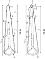
Figure 2A shows a perspective view of an alternate embodiment of a needle magnetizer of the present disclosure; -
Figure 2B shows a perspective view of an alternate embodiment of a needle magnetizer shown inFigure 2A of the present disclosure; -
Figure 2C shows a perspective view of an alternate embodiment of a needle magnetizer of the present disclosure; -
Figure 2D shows a perspective view of an alternate embodiment of a needle magnetizer shown inFigure 2C of the present disclosure; -
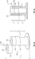
Figure 3A shows a perspective view of yet another alternate embodiment of a needle magnetizer of the present disclosure; -
Figure 3B illustrates a cross-section view of the needle magnetizer shown inFigure 3A of the present disclosure; and -
Figure 4 illustrates a cross-section view of yet another alternate embodiment of a needle magnetizer of the present disclosure. - Before describing several exemplary embodiments of the disclosure, it is to be understood that the description provided is not limited to the details of construction or process steps set forth in the following description. The devices and methods described herein are capable of other embodiments and of being practiced or being carried out in various ways.
- In this disclosure, a convention is followed wherein the distal end of the device is the end closest to a patient and the proximal end of the device is the end away from the patient and closest to a practitioner.
- Aspects of the disclosure pertain to an improved system that addresses the challenges to the existing technology and systems to magnetize a needle, such as a needle used with a peripheral intravenous (IV) catheter. Aspects of the disclosure pertain to an improved device and system that helps maintain the sterility of the tissue-penetrating device and also prevents damage to the distal tip of the tissue penetrating device during magnetization of the tissue penetrating device. Therefore, in one or more embodiments of the present disclosure, a tissue penetrating device is magnetized with the cover of the present disclosure placed on the tissue penetrating device. The section of the tissue penetrating device, e.g. needle, near the distal end to be magnetized is the same regardless of actual needle length.
- One or more embodiments of the present disclosure relate to a needle magnetizer that is capable of accommodating needles of various lengths with a cover of the present disclosure placed on the tissue penetrating device. In an alternate embodiment of the present disclosure, a needle magnetizer is capable of accommodating needles of various lengths without a cover being placed on the tissue penetrating device. According to one or more embodiments, the device and system of the present disclosure consistently magnetizes needles of various lengths with a cover of the present disclosure placed on the tissue penetrating device. In one or more embodiments of the present disclosure, a tissue penetrating device is magnetized without a cover placed on the tissue penetrating device. In one or more embodiments, the devices and systems described herein provide more precise control of the location of the magnet relative to the device to be magnetized, resulting in a more consistent and predictable magnetic field applied to the invasive medical device. In one or more embodiments, the devices and methods described herein create no additional risk of needle damage compared to existing magnetizer devices and no additional risk for contamination compared to existing magnetizer devices. Rather, the devices, system and methods described herein reduce the risk of needle damage compared to existing magnetizer devices and reduce the risk for contamination compared to existing magnetizer devices.
- Referring now to
Figure 1 , one aspect of the disclosure pertains to acover 10 for a tissue-penetrating medical device 80, the cover having asleeve member 14 having ahollow body 20 having adistal end 21, an openproximal end 22, aninner surface 23 andouter surface 24 to form a protective closure over a shaft of a tissue-penetrating medical device. In one or more embodiments, thehollow body 20 can be tubular or any other suitable shape. - In one or more embodiments,
distal end 21 may be open. In one or more embodiments,distal end 21 may be closed. -
Cover 10 can be used with tissue-penetrating medical devices, e.g. needles, with various lengths. As shown inFigure 1 , in one or more embodiments, theouter surface 24 of thesleeve member 14 includes a graduatedinjection depth gauge 25 having one or more lines (26, 27, 28, 29) to show how far to insertcover 10 into a magnetizer (not shown) for various desired lengths of needle magnetization. In one or more embodiments, multiple markings, e.g. lines (26, 27, 28, 29), can be placed oncover 10, whereby each marking corresponds to a different needle length to be used withcover 10. For example, in one or more embodiments, as shown inFigure 1 , ifcover 10 is intended to cover tissue penetrating devices having four (4) different lengths, there would be four (4) lines (26, 27, 28, 29) on theouter surface 24 of thesleeve member 14 ofcover 10. The distance from the distal end of the tissue penetrating devices, e.g. needle, to the marking for the given needle length is the same for all needle lengths with their corresponding markings, e.g. lines (26, 27, 28, 29). This way the length of needle tip section magnetized will be the same if the needle cover marking for the given needle length is aligned with a feature on a magnetizer. A tissue penetrating device is placed intocover 10 via opening 30 of openproximal end 22.Cover 10 is then inserted into a magnetizer (not shown), and the user aligns lines (26, 27, 28, 29) of graduatedinjection depth gauge 25 to the desired intended length of needle magnetization. In one or more embodiments, lines (26, 27, 28, 29) of graduatedinjection depth gauge 25 provide visual confirmation to the user by indicating needle penetration depth when the cover is placed into a magnetizer. - In one or more embodiments, the graduated
injection depth gauge 25 may be printed onto anouter surface 24 of thesleeve member 14. In another embodiment, the graduated injection depth gauge may be engraved, etched, embossed, debossed by molding or formed onto anouter surface 24 of thesleeve member 14 to assist the user in measuring the needle depth penetration. In one or more embodiments, the graduated injection depth gauge is scaled to correlate to a needle length. - Typically, manufacturers use same needle cover for devices with different needle lengths and gauges. Therefore, the distances between the tips of the needle cover and the needle vary depending on the needle length and needle cover design. However, these distances are known to manufacturers and fixed for a given needle length and needle cover design. Therefore, a marking or graduated injection depth gauge on the needle cover that indicates the position of the needle tip or the desired length of the magnetized needle section would allow clinicians to insert the corrected length of the needle into the magnetizer, thus overcoming the shortcoming of the existing technology. Similarly, a needle cover design with same distance between needle tip and needle cover tip would achieve the same outcome.
- A tissue-penetrating medical device 80 can include a needle assembly including a needle housing 81 and a shaft 82 of the needle having a sharp distal tip 84. In one or more embodiments, the
sleeve member 14 can be transparent to allow the shaft and needle cannula of a tissue-penetrating medical device to be visible. Thesleeve member 14 has a length L that covers the shaft of the tissue-penetrating medical device, including the sharp distal tip to prevent accidental needle sticks. The arrows shown inFigure 1 with respect to the length "L" also show the longitudinal axis of a needle shaft. Theopen end 22 of thehollow body 20 provides a device-receivingspace 40 for receiving at least the shaft 82 of the tissue-penetrating medical device 80. - The device-receiving
space 40 is sized and shaped to permit movement of the shaft of the tissue-penetrating medical device into and out of the device-receivingspace 40. In one embodiment, the device-receivingspace 40 permits movement of the shaft of the tissue-penetrating medical device into the device-receivingspace 40 in a movement that is parallel to the longitudinal axis of the shaft of tissue-penetrating medical device. The needle cannula magnetizes when the needle cannula, withcover 10, is inserted into a separate magnetizer (not shown). In an alternate embodiment, the needle cannula magnetizes when the needle cannula, withoutcover 10, is inserted into a separate magnetizer (not shown). The needle cannula magnetizes when the needle cannula, withcover 10, is inserted into a separate magnetizer (not shown). In one or more embodiments, a magnetizer consists of a cavity with at least one opening through which the needle can be inserted. The cavity and the opening are large enough to accommodate the tissue-penetrating medical device with its cover, thus ensuring the sterility and the integrity of the tissue-penetrating medical device. The cavity of the magnetizer can have openings on both ends to allow tissue-penetrating medical device, withcover 10, of various lengths and widths to be inserted into the magnetizer to a desired depth for magnetization. In an alternate embodiment, the cavity of the magnetizer can have openings on both ends to allow tissue-penetrating medical device, withoutcover 10, of various lengths and widths to be inserted into the magnetizer to a desired depth for magnetization. - A magnetizer further consists of magnetizing means around the cavity such as permanent magnets or electro-magnets, or other magnetizing means. A section of the tissue-penetrating medical device that is exposed to the magnetizing means is magnetized as the tissue-penetrating medical device is inserted and removed from the magnetizer.
- In use, the user would insert the tissue-penetrating medical device with
cover 10 into the magnetizer until the graduatedinjection depth gauge 25 on theouter surface 24 ofsleeve member 14 is aligned with the top of the magnetizer. When the tissue-penetrating medical device is removed from the magnetizer, the desired section of the tissue-penetrating medical device, e.g. needle, would be magnetized. The graduatedinjection depth gauge 25 on theouter surface 24 ofsleeve member 14 can be located at different locations along theouter surface 24 depending on the length and/or gauge of the tissue-penetrating medical device, e.g. needle. In one or more embodiments, cover 10 is sterile. In one or more embodiments, cover 10 is disposable. In one or more embodiments, cover 10 is plastic. - A second aspect of the present disclosure pertains to one or more tissue-penetrating medical device covers, such that the cover that can be used for tissue-penetrating medical device, e.g. needles, with different lengths In one or more embodiments, each
cover physical stop elements 150 are disposed on the outer surface ofcover physical stop elements 150 are molded onto the outer surface ofcover physical stop elements 150 disposed on the outer surface ofcover cover physical stop elements 150 disposed on the outer surface ofcover cover physical stop elements 150 disposed on the inner surface of a magnetizer correspond to different gauge or size of various tissue-penetrating medical devices to be used withcover physical stop elements 150 disposed on the outer surface ofcover - As shown in
Figure 2A and Figure 2B , a second aspect of the present disclosure, pertains to cover 110 and cover 120 which are designed to have a uniform fixed length between open proximal end (122, 132) and distal end (121, 131) of cover (110, 120) to enclose a tissue-penetrating medical device (160, 170). Therefore, thecover Figs. 2A and 2B . - A tissue-penetrating medical device can include a needle assembly including a needle housing and a shaft of the needle having a sharp distal tip. The open
proximal end 122 of cavity 161 provides a device-receiving space for receiving at least the shaft of the tissue-penetrating medical device (160, 170). - With respect to
Figure 2A and 2B , length L1 refers to the length between open proximal end (122, 132) of cover (110, 120) and the distal tip (162, 172) of a tissue penetrating medical device (160, 170). - Length L1 represents the length to cover the shaft of a tissue-penetrating medical device, including the sharp distal tip to prevent accidental needle sticks. With respect to
Figures 2A and 2B , length L2 refers to the length between the distal tip (162, 172) of a tissue penetrating medical device (160, 170) to enclose a tissue-penetrating medical device and the distal end (121, 131) of cover (110, 120). In one or more embodiments, cover (110,120) can be tubular or any other suitable shape. With respect toFigure 2A and 2B , length L3 refers to the length between the open proximal end (122, 132) of cover (110,120) and the distal end (121, 131) of cover (110, 120). In one or more embodiments, distal end (121, 131) may be open. In one or more embodiments, distal end (121, 131) may be closed. When a cover (110, 120) encloses a tissue-penetrating medical device (160, 170) and both are inserted into a magnetizer such that the distal end (121, 131) of cover (110, 120) contacts the bottom of a cavity of a magnetizer orphysical stop elements 150 disposed on the outer surface ofcover - Cover (110, 120) is sized and shaped to permit movement of the shaft of the tissue-penetrating medical device (160, 170) into and out of the device-receiving space. In one embodiment, cover (110, 120) permits movement of the shaft of the tissue-penetrating medical device (160, 170) into the cover (110, 120) 160 in a movement that is parallel to the longitudinal axis of the shaft of tissue-penetrating medical device. A metal portion of the tissue penetrating medical device (160, 170) magnetizes when the tissue penetrating medical device (160, 170), when cover (110,120) is inserted into a separate magnetizer. In an alternate embodiment, the metal portion of the tissue penetrating device magnetizes when the tissue penetrating device, without cover (110,120) is inserted into a separate magnetizer. The magnetizer consists of a cavity with at least one opening through which the cover (110, 120) can be inserted. The cavity and the opening of the magnetizer are large enough to accommodate the tissue penetrating medical device (160, 170) with cover (110, 120) to ensure the sterility and the integrity of the tissue penetrating medical device (160, 170) and its distal tip (162, 172). The magnetizer can have openings on both ends to allow tissue penetrating devices with various lengths and cover 110 of various length L3 to be inserted to desired depth. In one or more embodiments, distal end (121, 131) is open. In one or more embodiments, distal end (121, 131) is closed.
- The magnetizer further consists of magnetizing means around the cavity such as permanent magnets or electro-magnets, or other magnetizing means. A section of the tissue penetrating medical device (160, 170) that is exposed to the magnetizing means is magnetized as the tissue penetrating medical device (160, 170) is inserted and removed from the magnetizer. The magnetizer can have openings on both ends to allow tissue penetrating medical devices (160, 170) with various length L1 and cover 110 or cover 120 of various lengths L3 to be inserted to desired depth.
- In one or more embodiments, as shown in
Figure 2A , length L1 is less than length L3. In one or more embodiments, as shown inFigure 2A , length L2 is less than length L3. In one or more embodiments, as shown inFigure 2A , length L3 is about the sum of L1 and length L2. In one or more embodiments, as shown inFigure 2B , length L1 is approximately the same as length L3. In one or more embodiments, each of thephysical stop elements 150 disposed on the outer surface ofcover - As shown in
Figure 2C , in conjunction withFigure 2D ,, an alternate embodiment, pertains to cover 110 and cover 120 which are designed to have different fixed lengths between thedistal tip 162 of a cavity 161to enclose a tissue-penetrating medical device and thedistal end 121 ofcover 110 ordistal tip 131 ofcover 120. Therefore, thecover - With respect to
Figure 2C , length L1 refers to the length between openproximal end 122 ofcover 110 and thedistal end 262 of acavity 260 to enclose a tissue-penetrating medical device. In one or more embodiments,distal end 121 ofcover 110 may be open. In one or more embodiments,distal end 121 ofcover 110 may be closed. - A tissue-penetrating medical device can include a needle assembly including a needle housing and a shaft of the needle having a sharp distal tip. The open
proximal end 122 of cavity 161 provides a device-receiving space for receiving at least the shaft of the tissue-penetrating medical device. - Length L1 represents the length to cover the shaft of a tissue-penetrating medical device, including the sharp distal tip to prevent accidental needle sticks. With respect to
Figure 2C , length L2 refers to the length between thedistal end 262 of a cavity 161 to enclose a tissue-penetrating medical device and thedistal end 121 ofcover 110. In one or more embodiments, thecavity 260 can be tubular or any other suitable shape. With respect toFigure 2C , length L3 refers to the length between the openproximal end 122 ofcover 110 and thedistal end 121 ofcover 110. When acover 110 encloses a tissue-penetrating medical device and both are inserted into a magnetizer such that thedistal end 121 ofcover 110 contacts the bottom of a cavity of a magnetizer, a desired section of the tissue-penetrating medical device of length L1 will be exposed to the magnetic field to be magnetized. - The
cavity 260 is sized and shaped to permit movement of the shaft of the tissue-penetrating medical device into and out of the device-receiving space. In one embodiment, thecavity 260 permits movement of the shaft of the tissue-penetrating medical device into thecavity 260 in a movement that is parallel to the longitudinal axis of the shaft of tissue-penetrating medical device. A metal portion of the tissue penetrating device magnetizes when the tissue penetrating device, withcover 110, is inserted into a separate magnetizer. In an alternate embodiment, the metal portion of the tissue penetrating device magnetizes when the tissue penetrating device, withoutcover 110, is inserted into a separate magnetizer. The magnetizer consists of a cavity with at least one opening through which the needle can be inserted. The cavity and the opening of the magnetizer are large enough to accommodate the tissue penetrating device with its cover thus ensures the sterility and the integrity of the needle. The magnetizer can have openings on both ends to allow tissue penetrating devices with various lengths and cover 110 of various length L3 to be inserted to desired depth. - The magnetizer further consists of magnetizing means around the cavity such as permanent magnets or electro-magnets, or other magnetizing means. A section of the needle that is exposed to the magnetizing means is magnetized as the needle is removed from the magnetizer.
- With respect to
Figure 2D , length L1 refers to the length between openproximal end 132 ofcover 120 and thedistal tip 172 of acavity 270 to enclose a tissue-penetrating medical device. A tissue-penetrating medical device (not shown) can include a needle assembly including a needle housing and a shaft of the needle having a sharp distal tip. The openproximal end 132 ofcavity 270 provides a device-receiving space for receiving at least the shaft of the tissue-penetrating medical device. - Length L1 represents the length to cover the shaft of a tissue-penetrating medical device, including the sharp distal tip to prevent accidental needle sticks. With respect to
Figure 2D , length L2 refers to the length between thedistal tip 272 of acavity 270 to enclose a tissue-penetrating medical device and thedistal tip 131 ofcover 120. In one or more embodiments, thecavity 270 can be tubular or any other suitable shape. With respect toFigure 2D , length L3 refers to the length between the openproximal end 132 ofcover 120 and thedistal tip 131 ofcover 120. When acover 120 encloses a tissue-penetrating medical device and both are inserted into a magnetizer such that thedistal tip 131 ofcover 120 contacts the bottom of a cavity of a magnetizer, a desired section of the tissue-penetrating medical device of length L1 will be exposed to the magnetic field to be magnetized. - The
cavity 270 is sized and shaped to permit movement of the shaft of the tissue-penetrating medical device into and out of the device-receiving space. In one embodiment, thecavity 270 permits movement of the shaft of the tissue-penetrating medical device into thecavity 270 in a movement that is parallel to the longitudinal axis of the shaft of tissue-penetrating medical device. A metal portion of the tissue penetrating device magnetizes when the tissue penetrating device, withcover 120, is inserted into a separate magnetizer. In an alternate embodiment, a metal portion of the tissue penetrating device magnetizes when the tissue penetrating device, withoutcover 120, is inserted into a separate magnetizer. The magnetizer consists of a cavity with at least one opening through which the needle can be inserted. The cavity and the opening of the magnetizer are large enough to accommodate the tissue penetrating device with its cover thus ensures the sterility and the integrity of the needle. The magnetizer can have openings on both ends to allow tissue penetrating devices with various length and cover 110 or cover 120 of various lengths L3 to be inserted to desired depth. - In one or more embodiments, as shown in
Figure 2C , length L1 is less than length L3. In one or more embodiments, as shown inFigure 2C , length L2 is less than length L3. In one or more embodiments, as shown inFigure 2C , length L3 is about the sum of L1 and length L2. In one or more embodiments, as shown inFigure 2D , length L1 is approximately the same as length L3. - The magnetizer further consists of magnetizing means around the cavity such as permanent magnets or electro-magnets, or other magnetizing means. A section of the needle that is exposed to the magnetizing means is magnetized as the needle is removed from the magnetizer.
- In one or more embodiments, the
cover 110 and cover 120 can be transparent to allow the shaft and needle cannula of a tissue-penetrating medical device to be visible. In alternate embodiments,cover 110 and cover 120 can be opaque. - It is contemplated that in one or more embodiments, an outside surface of
cover 110 or cover 120 may have a graduated injection depth gauge or marking to indicate the desired section of the needle to be magnetized when the needle and the needle cover are inserted into a magnetizer. In one or more embodiments, the graduated injection depth gauge may be printed onto an outer surface of thecover 10. In another embodiment, the graduated injection depth gauge may be engraved, etched, embossed, debossed by molding or formed onto an outer surface of thecover 110 or cover 120 to assist the practitioner in measuring the needle depth penetration. In one or more embodiments, the graduated injection depth gauge is scaled to correlate to a needle length. - In use, the user would insert the tissue-penetrating medical device with
cover 110 or cover 120 into a magnetizer to magnetize a desired portion of the tissue-penetrating medical device. In one or more embodiments, lengths L1, L2 and/or L3 may be varied depending on the length and/or gauge of the desired tissue-penetrating medical device. Thecover 110 or cover 120 may have lines on it to show how far to insert cover for each needle length. The needle is inserted into a magnetizer with the cover on to contact the bottom of the magnetizer in order to obtain the desired length of magnetization without any additional action on the part of the user. - In one or more embodiments, the cover is sterile. In one or more embodiments, the cover is disposable. In one or more embodiments, the cover is plastic.
- A third aspect of the present disclosure, as shown in
Figure 3A and Figure 3B , pertains to, amagnetizer 300 having abase segment 310 having one ormore magnets 320, and one or more movable segments (330, 340) stacked in a vertical configuration on top ofbase segment 310. In one or more embodiments, movable segments (330, 340) may be in the form of a ring. - The
base segment 310 and movable segments (330, 340) having acentral cavity 360. The one or more of the movable segments (330, 340) pivot or move around ahinge 370 havingvertical axis 380 not in contact with thecavity 360. In one or more embodiments, movable segments (330, 340) have one ormore magnets 320. In one or more embodiments,magnetizer 300 as shown inFigure 3A and Figure 3B , can accommodate a needle cover of a uniform fixed length that can be used for needles of various different lengths. Thus, the insertion depth of the cover with respect to the bottom of thecavity 360 of themagnetizer 300 will be kept the same for needles of various different lengths. The number of the movable segments (330, 340) atopbase segment 310 can be adjusted via moving the movable segments (330, 340) to correspond to the desired needle length enclosed in the cover. In one or more embodiments, when magnetizing a needle of shortest length, all movable segments (330, 340) atopbase segment 310 will be used to form the magnetizingcavity 360. When magnetizing a needle of longest length, only thebase segment 310 is used for magnetizing the needle, while the other movable segments (330, 340) are moved out of the place. Therefore, movement of the movable segments adjusts the distance between the bottom of the magnetizingcavity 360 and the top of themagnetizer 300. - To adjust the length of the magnetizer to adjust to a tissue penetrating device or cover of various lengths, one or more of the movable segments (330, 340) can be moved or rotated about the
axis 380 so that the one or more of the movable segments (330, 340) is out of the way when tissue penetrating devices, e.g. needles, with different lengths are inserted intocavity 360 of themagnetizer 300 to be magnetized. - Referring initially to
Figure 3A , themagnetizer 300 in accordance with an embodiment of the present disclosure has acavity 360 formed in between a plurality of two or more movable segments (330, 340) andbase segment 310 which are stacked and centered about avertical axis 380. Each movable segment (330, 340) andbase segment 310 has acenter cavity 360 of sufficient size to receive a tissue-penetrating medical device, e.g. needles, of various lengths with a cover covering a portion or the entirety of the tissue-penetrating medical device. Thecavity 360 of each movable segment (330, 340) andbase segment 310 can be arranged and aligned in a circular array that is concentric with theaxis 380 such that a tissue penetrating device may be inserted intocavity 360.Cavity 360 is of sufficient size to receive a tissue-penetrating medical device, e.g. needles, of various lengths with a cover covering a portion or the entirety of the tissue-penetrating medical device. In one or more embodiment,base segment 310 can have an open proximal end and an open distal end. In one or more embodiment,base segment 310 can have an open proximal end and a closed distal end. In one or more embodiment,base segment 310 can have a closed proximal end and an open distal end. In one or more embodiments, the movable segments (330, 340) can be moved in rotational motion aboutaxis 380 and may move or rotate in opposite directions or in the same direction. Each movable segment (330, 340) may be embedded with one ormore magnets 320. In one or more embodiments,magnet 320 is a permanent magnet. Certain of the above described characteristics of this embodiment of the invention are for purposes of example and can vary in other embodiments of the invention. In one or more embodiments, the number of segments, and their respective cavities, will depend on the dimensions including size, shape, height, length, etc. of the desired cover or tissue penetrating device to be magnetized by the magnetizer. Each of the one or more movable segments (330, 340) andbase segment 310 may be of various size, shape, length, height, diameter, radius, etc. depending on the desired tissue penetrating device and/or cover to be inserted into the magnetizer comprised of one or more movable segments (330, 340) andbase segment 310. - As shown in
Figure 3A , the movable segments (330, 340) are supported by abase segment 310, which may be in the form of an upright cylinder which extends upward. Each movable segment (330, 340) has a central extending cylindrical cavity to accommodate a tissue-penetrating medical device, e.g. needles, of various lengths with a cover covering a portion or the entirety of the tissue-penetrating medical device. Each segment can be in coaxial relationship withbase segment 310. Ahinge 370 couples each movable segment (330, 340) to support thebase segment 310 while enabling movement or rotation of the each movable segment (330, 340). - In one or more embodiments each segment may be embedded with one or
more magnet 320. In one or more embodiment,magnet 320 can be a permanent magnet. In one or more embodiments, one or more segments may be moved or rotated about the vertical axis to vary the length of the cavity in which the tissue penetrating device is placed. Therefore, by moving one or more segments about the vertical axis, the length of the cavity can be adjusted to a desired length. Therefore, the user can control the portion or length of the tissue penetrating device to be magnetized. For example, as shown inFigure 3B ,base segment 310 has a length L1,segment 330 has a length L2 andsegment 340 has a length L3. Depending on the length of the cover or tissue penetrating device to be magnetized, one or more segments may be moved about the vertical axis to vary the length of the cavity in which the tissue penetrating device is placed. In one or more embodiments, movement may be rotational or translation. For example, if the desired length of the cover or tissue penetrating device to be magnetized is L1, then bothsegment 330 andsegment 340 can be moved or rotated about the vertical axis to adjust the length of the cavity to L1 in which the tissue penetrating device is placed. For example, if the desired length of the cover or tissue penetrating device to be magnetized is L4, thensegment 340 can be moved or rotated about the vertical axis to adjust the length of the cavity to L4 (sum of L1 and L2) in which the tissue penetrating device is placed. For example, if the desired length of the cover or tissue penetrating device to be magnetized is L5, then none of the segments (340, 350) are moved or rotated about the vertical axis, insteadsegment 340 and segment 350 are aligned withbase segment 310 to adjust the length of the cavity to L5 (sum of L1, L2 and L3) in which the tissue penetrating device is placed. Therefore, the user can control the portion or length of the tissue penetrating device to be magnetized. - In one or more embodiments,
magnetizer 300 may be used with anycover physical stop elements 150 disposed on the outer surface and is used with a tissue penetrating device of variable lengths. In one or more embodiments, one or morephysical stop elements 150 are molded onto the outer surface ofcover physical stop elements 150 disposed on the outer surface ofcover cover magnetizer 300 until thephysical stop elements 150 disposed on the outer surface ofcover magnetizer 300. Therefore, the length or portion of the tissue-penetrating device that is magnetized is dependent on the length of the tissue penetrating device within thecover -
Magnetizer 300 can be used as a single use disposable item, or themagnetizer 300 may be reusable since the needle cover stays in place during the magnetization step. In other embodiments, the length L1 ofbase segment 310, L2 and L3 of the respective segments (330, 340) and length L4, L5 ofmagnetizer 300 may be configured such that the entire or a desired portion of a shaft of the tissue-penetrating medical device can be magnetized. In other embodiments, the length L1, L2, L3, L4 and L5 can be 10%, 20%, 30%, 40%, 50%, 60%, 70%, 80%, 90%, 100 % or any intervening percentage of the length of the cover or tissue penetrating device to be magnetized. -
Figure 3B shows a cross-sectional view of amagnetizer 300 having one or more embeddedmagnets 320 in the sidewall of the base segment and respective segments (330, 340) of themagnetizer 300. The one ormore magnets 320 can be embedded in a slot. The one ormore magnets 320 can be sized to be slidably mounted within a slot or held in place by friction fit, or the one ormore magnets 320 can be attached with an adhesive or other suitable ways. Alternatively, one ormore magnets 320 can be integrally molded in the sidewall of thebase segment 310 and respective segments (330, 340) of themagnetizer 300. In one or more embodiments, the magnet may be a permanent magnet, electro-magnets, or other magnetizing means. - In one or more embodiments,
magnetizer 300 allows magnetic pole tip position to be changed with respect to the magnetizer cavity, particularly for the cases of where the magnetizer cavity only contains one opening. The top of the magnetizing means can be changed to be closer to the bottom of the cavity when magnetizing a needle with longer length. - A fourth aspect of the present disclosure, as shown in
Figure 4 , pertains to amagnetizer 400, having an openproximal end 402, adistal end 404, afirst sidewall 406, a first slidingelement 410 having one or morefirst magnets 412 slidably connected to thefirst sidewall 406, asecond sidewall 414, a second slidingelement 418 having one or moresecond magnets 420 slidably engaged to thesecond sidewall 414, acavity 422 formed between thefirst sidewall 406,second sidewall 414 anddistal end 404. The one or more first magnets are mounted on the first slidingelement 410. The one or moresecond magnets 420 are mounted on the second slidingelement 418. The first slidingelement 410 and the second slidingelement 418 can be moved in parallel to the axis of thecavity 422 to adjust the length of the magnetizer to magnetize atissue penetrating device 500 or cover 600 of various lengths that are inserted intocavity 422 of themagnetizer 400 allowing the adjustment of the distance between the bottom of the magnetizingcavity 422 and the top of the magnet (412/420). In one or more embodiments,first sidewall 406 can have afirst slot 408, a first slidingelement 410 having one or morefirst magnets 412, first slidingelement 410 being slidably connected to thefirst slot 408, asecond sidewall 414 having asecond slot 416, a second slidingelement 418 having one or moresecond magnets 420, second slidingelement 418 being slidably engaged to thesecond slot 416, acavity 422 formed between thefirst sidewall 406,second sidewall 414 anddistal end 404. - One or more embodiments of the present disclosure relate to a needle magnetizer that is capable of accommodating
tissue penetrating device 500 or cover 600 of various lengths. - The
cavity 422 is sized and shaped to permit movement of thetissue penetrating device 500 or cover 600 into and out ofcavity 422. In one embodiment, thecavity 422 permits movement of thetissue penetrating device 500 or cover 600 into thecavity 422 in a movement that is parallel to the longitudinal axis of the shaft of tissue-penetrating medical device. The needle cannula magnetizes when thetissue penetrating device 500 or cover 600 are placed intocavity 422 and subsequently first slidingelement 410 and/or second slidingelement 418 are moved in parallel to the axis of thecavity 422 to adjust the length of the magnetizer to magnetize a desired portion of thetissue penetrating device 500 or cover 600 of various lengths that are inserted intocavity 422 of themagnetizer 400. The magnetizer consists of a cavity with at least one openproximal end 402 through which thetissue penetrating device 500 or cover 600 can be inserted. Thecavity 422 and the openproximal end 402 are large enough to accommodate thetissue penetrating device 500 or cover 600 of various dimensions and lengths that are inserted intocavity 422 of themagnetizer 400 therefore ensuring the sterility and the integrity of the tissue penetrating device. It is contemplated that in one or more embodiment,cavity 422 can have openings on both ends to allow needles with various length and needle cover length to be inserted to desired depth. - The first sliding
element 410 and/or second slidingelement 418 may be variably positioned along the length L of thecover 600 relative to the shaft of thetissue penetrating device 500 to allow the user to control the portion or length of thetissue penetrating device 500 to be magnetized. Themagnetizer 400 can be used as a single use disposable item, or themagnetizer 400 may be reusable since thecover 600 stays in place during the magnetization step. Therefore, the user can control the portion or length of thetissue penetrating device 500 to be magnetized. The slider can be slidably moved along the length of thecover 600 via thefirst slot 408 and thesecond slot 416. In other embodiments, the length of thefirst slot 408 and thesecond slot 416 may be equal to the length L of thecover 600 ortissue penetrating device 500 such that the entire shaft of the tissue-penetratingmedical device 500 can be magnetized. In other embodiments, the any desired portion (e.g. 10%, 20%, 30%, 40%, 50%, 60%, 70%, 80%, 90%, 100% or any increment therein) of the length L of the penetratingmedical device 500 can be magnetized. - Magnet (412, 420) can be attached to the sliding elements (410, 418) with an adhesive or other suitable ways. Alternatively, the magnets (412, 420) could be integrally molded into sliding element (410, 418).
- The magnet (412, 420) can be sized to be slidably mounted within the first sidewall (406) and/or second sidewall (414). In one or more embodiments, the magnet (412, 420) can be sized to be slidably mounted within the slot (408, 416).
- In one or more embodiments, the magnet (412, 420) may be a permanent magnet, electro-magnets, or other magnetizing means.
- It is contemplated that the
first sidewall 406 and/orsecond sidewall 414 can have a graduated injection depth gauge or marking 430 to indicate the desired length or section of the needle to be magnetized when the needle and the needle cover are inserted into a magnetizer. In one or more embodiments, the graduated injection depth gauge may be printed onto an outer surface of thefirst sidewall 406 and/orsecond sidewall 414. In another embodiment, the graduated injection depth gauge may be engraved, etched, embossed, debossed by molding or formed onto an outer surface of thefirst sidewall 406 and/orsecond sidewall 414 to assist the practitioner in measuring the needle depth penetration. In one or more embodiments, the graduated injection depth gauge is scaled to correlate to a needle length. - In one or more embodiments, the first sliding
element 410 and/or second slidingelement 418 includes a contact surface having a profile for accommodating a practitioner's finger. - First sliding
element 410 and/or second slidingelement 418 may be configured to toggle in a parallel or perpendicular direction with respect totissue penetrating device 500 orcover 600. - Movement of the first sliding
element 410 and/or second slidingelement 418 from a forward end of thefirst sidewall 406 to the rearward end of thesecond sidewall 414 may be accomplished by exerting pressure onfinger contact surface 440 of the first slidingelement 410 and/or second slidingelement 418. -
Figure 4 show a tissue-penetratingmedical device 500, acover 600 for magnetizing the shaft 134 of the tissue-penetrating medical device 130. Thecover 600 includes asleeve member 602 having a hollowtubular body 604 having adistal end 606 and a proximal end (not shown) to form a protective closure over theshaft 608 of the tissue-penetratingmedical device 500, thesleeve member 602 having a length L to cover theshaft 608 of the tissue-penetratingmedical device 500, theshaft 608 having a length L2 and adistal tip 610. An open end (not shown) of the hollowtubular body 604 provides a receiving space for receiving at least theshaft 608 of the tissue-penetratingmedical device 500. In one or more embodiments, a single magnet can be utilized to magnetize theshaft 608, or more than two magnets can also be utilized. - In embodiments in which two magnets are utilized, the orientation of the magnetic fields of the two magnets can vary. One magnet can have north and south poles on axis with shaft of the tissue-penetrating medical device, while the second magnet can have north and south poles off-axis or perpendicular to the shaft of the tissue-penetrating medical device. Alternatively, the two magnets both can have north and south poles off axis with the shaft of the tissue-penetrating medical device, or the two magnets both can have north and south poles on axis with the shaft of the tissue-penetrating medical device.
- Upon removal from
magnetizer 400, the tissue-penetratingmedical device 500 can now be used with a procedural guidance system that utilize magnetic sensors as a means of measuring and predicting needle tip location relative to the target anatomy. - In one or more embodiments,
magnetizer 400 allows magnetic pole tip position to be changed with respect to the magnetizer cavity, particularly for the cases of where the magnetizer cavity only contains one opening. The top of the magnetizing means can be changed to be closer to the bottom of the cavity when magnetizing a needle with longer length. - In alternative embodiments, a needle cover is provided that has geometric dimensions that permit the needle cover to be placed inside existing needle magnetizing devices while the needle cover is covering the shaft of the needle. The distal end of the needle cover may be used to limit the depth of insertion by providing a stop to contact the bottom of the needle magnetizing device. Alternatively, a feature near the proximal portion of the needle cover can be provided on the cover to limit the depth of insertion by a stop on the proximal opening of the needle magnetizer.
- The covers described herein can have a variety of properties. In one or more embodiments, the covers are formed from plastic. In one or more embodiments, the covers are sterile. In one or more embodiments, the covers are disposable. In other embodiments, the covers may be both sterile and disposable.
- The tissue-penetrating medical device may be a needle, catheter, introducer needle, stylet, scalpel or guidewire. In one embodiment, the tissue-penetrating medical device is a needle, which when magnetized can be used with a procedural guidance system to locate and project the position of the needle during an invasive medical procedure. The tissue-penetrating medical device according to one or more embodiments is includes a magnetizable metallic material. In a specific embodiment, the magnetizable metallic material is stainless steel.
- The covers described herein may also be incorporated into a vascular access device comprising a catheter, a catheter adapter subassembly, and a needle subassembly including an introducer needle, a needle hub connected to the proximal end of the introducer needle and a needle cover according to any of the embodiments described herein. The magnetizer of the present disclosure may also be used in conjunction with a vascular access device comprising a catheter, a catheter adapter subassembly, and a needle subassembly including an introducer needle.
- Another aspect of the disclosure pertains to a method of magnetizing a tissue-penetrating medical device. Embodiments of the method include positioning a shaft of a tissue-penetrating medical device in a cover of the present disclosure including a device-receiving space, positioning the cover including tissue-penetrating medical device into a magnetizer and removing the cover with the tissue-penetrating medical device from the magnetizer to magnetize a desired portion of the tissue-penetrating medical device. Another embodiment of the method of the present disclosure includes positioning a shaft of a tissue-penetrating medical device in an available cover having a device-receiving space, positioning the cover with the tissue-penetrating medical device into a magnetizer of the present disclosure, and removing the cover with the tissue-penetrating medical device from the magnetizer of the present disclosure to magnetize a desired portion of the tissue-penetrating medical device.
- Reference throughout this specification to "one embodiment," "certain embodiments," "one or more embodiments" or "an embodiment" means that a particular feature, structure, material, or characteristic described in connection with the embodiment is included in at least one embodiment of the disclosure. Thus, the appearances of the phrases such as "in one or more embodiments," "in certain embodiments," "in one embodiment" or "in an embodiment" in various places throughout this specification are not necessarily referring to the same embodiment of the disclosure. Furthermore, the particular features, structures, materials, or characteristics may be combined in any suitable manner in one or more embodiments.
- Although the disclosure herein has provided a description with reference to particular embodiments, it is to be understood that these embodiments are merely illustrative of the principles and applications of the present disclosure. It will be apparent to those skilled in the art that various modifications and variations can be made to the method and apparatus of the present disclosure without departing from the spirit and scope of the disclosure. Thus, it is intended that the present disclosure include modifications and variations that are within the scope of the appended claims and their equivalents.
Further Aspects are: - Aspect 1. A cover for magnetizing a tissue-penetrating medical device comprising:
a sleeve member having an open proximal end, a distal end, an inner surface, an outer surface, and a hollow body extending between the proximal end and the distal end to form a protective closure over a shaft of a tissue-penetrating medical device having a longitudinal axis, an open end of the sleeve member providing a receiving space for receiving at least the shaft of the tissue-penetrating medical device, the outer surface of the sleeve member having a graduated injection depth gauge to indicate needle penetration depth when the cover is placed into a magnetizer. - Aspect 2. The cover of aspect 1, wherein the graduated injection depth gauge is printed, engraved, etched, embossed, or debossed onto an outer surface of the sleeve member.
- Aspect 3. The cover of aspect 1, wherein the graduated injection depth gauge is scaled to correlate to a needle length.
- Aspect 5. The cover of aspect 1, wherein the cover is sterile.
- Aspect 5. The cover of aspect 1, wherein the cover is disposable.
- Aspect 6. The cover of aspect 1, wherein the cover comprises plastic.
- Aspect 7. A magnetizer for magnetizing a tissue-penetrating medical device comprising:
- a base segment having one or more magnets and a first central cavity;
- one or more movable segments having one or more magnets stacked in a vertical configuration on top of the base segment, the one or more movable segments having a second central cavity; and
- a hinge having a vertical axis not in contact with the first central cavity and second central cavity, the hinge connecting the one or more movable segments and the base segment.
- Aspect 8. The magnetizer of aspect 7, wherein the first central cavity and the second central cavity permits movement of a tissue-penetrating medical device into the first central cavity and the second central cavity in a direction parallel to a longitudinal axis of the tissue-penetrating medical device.
- Aspect 9. The magnetizer of aspect 7, wherein the first central cavity and the second central cavity permit movement of a shaft of the tissue-penetrating medical device into and out of a receiving space.
-
Aspect 10. The magnetizer of aspect 7, wherein there are two or more magnets disposed on the base segment. - Aspect 11. The magnetizer of aspect 7, wherein there are two or more magnets disposed on each of the one or more movable segments.
- Aspect 12. The magnetizer of aspect 7, wherein the one or more magnets are a fixed permanent magnet.
- Aspect 13. The magnetizer of
aspect 10, wherein the two or more magnets are a fixed permanent magnet. -
Aspect 14. A magnetizer for magnetizing a tissue-penetrating medical device comprising:- an open proximal end;
- a distal end;
- a first sidewall;
- a first sliding element having one or more first magnets slidably connected to the first sidewall;
- a second sidewall; and
- a cavity formed between the first sidewall, second sidewall and the distal end.
- Aspect 15. The magnetizer of
aspect 14, wherein the one or more first magnets are mounted on the first sliding element. - Aspect 16. The magnetizer of
aspect 14, further comprising a second sliding element having one or more second magnets slidably engaged to the second sidewall. - Aspect 17. The magnetizer of aspect 16, wherein the one or more second magnets are mounted on the second sliding element.
- Aspect 18. The magnetizer of
aspect 14, wherein the first sliding element is movable in a parallel direction to an axis of the cavity. - Aspect 19. The magnetizer of aspect 16, wherein the second sliding element is movable in a parallel direction to an axis of the cavity.
-
Aspect 20. The magnetizer ofaspect 14, wherein the first sliding element includes a contact surface having a profile for accommodating a practitioner's finger. -
Aspect 21. The magnetizer of aspect 16, wherein the second sliding element includes a contact surface having a profile for accommodating a practitioner's finger. -
Aspect 22. The magnetizer ofaspect 14, wherein the cavity is configured to accomodate a tissue-penetrating medical device. -
Aspect 23. The magnetizer ofaspect 22, wherein the tissue-penetrating medical device is a needle assembly, a stylet, catheter, introducer needle, scalpel or guidewire. -
Aspect 24. The magnetizer ofaspect 23, wherein the tissue-penetrating medical device includes a needle assembly including a needle and the shaft, and when the shaft is magnetized, the tissue-penetrating medical device is configured for use in a procedural guidance system to locate and project a position of the shaft during an invasive medical procedure. -
Aspect 25. The magnetizer ofaspect 14, wherein the cavity is configured to accommodate a needle cover. -
Aspect 26. The magnetizer ofaspect 14, wherein the one or more magnets comprises a fixed permanent magnet. -
Aspect 27. The magnetizer ofaspect 14, wherein the first slider element is moveable along the first sidewall. -
Aspect 28. The magnetizer of aspect 16, wherein the second slider element is moveable along the second sidewall. -
Aspect 29. A cover for magnetizing a tissue-penetrating medical device comprising:- a sleeve member having an open proximal end,
- a distal end, an inner surface,
- an outer surface,
- one or more physical stop elements disposed on the outer surface;
- and a hollow body extending between the proximal end and the distal end to form a protective closure over a shaft of a tissue-penetrating medical device .
-
Aspect 30. The cover ofaspect 29, wherein the one or more physical stop elements correspond to different needle lengths to indicate needle penetration depth when the cover is placed into a magnetizer. - Aspect 31. The cover of
aspect 29, wherein the one or more physical stop elements correspond to different needle gauges to indicate needle penetration depth when the cover is placed into a magnetizer.
Claims (9)
- A cover for magnetizing a tissue-penetrating medical device comprising:
a sleeve member having an open proximal end, a distal end, an inner surface, an outer surface, and a hollow body extending between the proximal end and the distal end to form a protective closure over a shaft of a tissue-penetrating medical device having a longitudinal axis, an open end of the sleeve member providing a receiving space for receiving at least the shaft of the tissue-penetrating medical device, the outer surface of the sleeve member having a graduated injection depth gauge to indicate needle penetration depth when the cover is placed into a magnetizer. - The cover of claim 1, wherein the graduated injection depth gauge is printed, engraved, etched, embossed, or debossed onto an outer surface of the sleeve member.
- The cover of claim 1, wherein the graduated injection depth gauge is scaled to correlate to a needle length.
- The cover of claim 1, wherein the cover is sterile.
- The cover of claim 1, wherein the cover is disposable.
- The cover of claim 1, wherein the cover comprises plastic.
- A cover for magnetizing a tissue-penetrating medical device comprising:a sleeve member having an open proximal end,a distal end, an inner surface,an outer surface,one or more physical stop elements disposed on the outer surface;and a hollow body extending between the proximal end and the distal end to form a protective closure over a shaft of a tissue-penetrating medical device.
- The cover of claim 7, wherein the one or more physical stop elements correspond to different needle lengths to indicate needle penetration depth when the cover is placed into a magnetizer.
- The cover of claim 7, wherein the one or more physical stop elements correspond to different needle gauges to indicate needle penetration depth when the cover is placed into a magnetizer.
Applications Claiming Priority (4)
| Application Number | Priority Date | Filing Date | Title |
|---|---|---|---|
| US201762481964P | 2017-04-05 | 2017-04-05 | |
| US15/944,324 US10765835B2 (en) | 2017-04-05 | 2018-04-03 | Needle magnetizer |
| EP18720488.8A EP3606587B1 (en) | 2017-04-05 | 2018-04-04 | Needle magnetizer |
| PCT/US2018/026077 WO2018187466A1 (en) | 2017-04-05 | 2018-04-04 | Needle magnetizer |
Related Parent Applications (1)
| Application Number | Title | Priority Date | Filing Date |
|---|---|---|---|
| EP18720488.8A Division EP3606587B1 (en) | 2017-04-05 | 2018-04-04 | Needle magnetizer |
Publications (1)
| Publication Number | Publication Date |
|---|---|
| EP4029551A1 true EP4029551A1 (en) | 2022-07-20 |
Family
ID=63710657
Family Applications (2)
| Application Number | Title | Priority Date | Filing Date |
|---|---|---|---|
| EP22153988.5A Pending EP4029551A1 (en) | 2017-04-05 | 2018-04-04 | Cover for needle magnetizer |
| EP18720488.8A Active EP3606587B1 (en) | 2017-04-05 | 2018-04-04 | Needle magnetizer |
Family Applications After (1)
| Application Number | Title | Priority Date | Filing Date |
|---|---|---|---|
| EP18720488.8A Active EP3606587B1 (en) | 2017-04-05 | 2018-04-04 | Needle magnetizer |
Country Status (12)
| Country | Link |
|---|---|
| US (3) | US10765835B2 (en) |
| EP (2) | EP4029551A1 (en) |
| JP (4) | JP7356353B2 (en) |
| CN (1) | CN212730610U (en) |
| AU (2) | AU2018250205B2 (en) |
| CA (2) | CA3057149C (en) |
| ES (1) | ES2908305T3 (en) |
| MX (2) | MX2019011942A (en) |
| MY (2) | MY209629A (en) |
| NZ (1) | NZ767511A (en) |
| SG (2) | SG11201908448XA (en) |
| WO (1) | WO2018187466A1 (en) |
Families Citing this family (16)
| Publication number | Priority date | Publication date | Assignee | Title |
|---|---|---|---|---|
| ES2848830T3 (en) * | 2017-04-27 | 2021-08-12 | Bard Access Systems Inc | Guiding system to guide the insertion of a needle into the body of a patient comprising a magnetization system for needle assemblies |
| ES2985141T3 (en) * | 2019-12-04 | 2024-11-04 | Bard Access Systems Inc | Needle guidance systems, components, and methods thereof |
| CN114246614B (en) | 2020-09-25 | 2025-09-23 | 巴德阿克塞斯系统股份有限公司 | Ultrasound imaging system and minimum catheter length tool |
| CR20230176A (en) | 2020-10-22 | 2024-03-18 | Sientra Inc | Systems and methods for tissue expansion |
| CN216417315U (en) * | 2020-11-09 | 2022-05-03 | 巴德阿克塞斯系统股份有限公司 | Magnetizer and related system |
| US12059243B2 (en) * | 2020-11-10 | 2024-08-13 | Bard Access Systems, Inc. | Sterile cover for medical devices and methods thereof |
| US12349983B2 (en) | 2021-03-05 | 2025-07-08 | Bard Access Systems, Inc. | Systems and methods for ultrasound-and-bioimpedance-based guidance of medical devices |
| US12605140B2 (en) | 2021-03-29 | 2026-04-21 | Bard Access Systems, Inc. | System and method for a vessel assessment tool |
| CN217982371U (en) * | 2021-06-22 | 2022-12-06 | 巴德阿克塞斯系统股份有限公司 | Magnetizer system for use with medical devices including ferrous elements |
| EP4358853A1 (en) | 2021-06-22 | 2024-05-01 | Bard Access Systems, Inc. | Ultrasound detection system |
| US12230427B2 (en) * | 2021-07-26 | 2025-02-18 | Bard Access Systems, Inc. | Medical-device magnetizer systems and methods |
| EP4404836A1 (en) * | 2021-09-29 | 2024-07-31 | Bard Access Systems, Inc. | Magnetic signature imprinting system |
| WO2023055958A1 (en) * | 2021-09-30 | 2023-04-06 | Bard Access Systems, Inc. | Magnetic signature imprinting system |
| CN115969409A (en) | 2021-10-14 | 2023-04-18 | 巴德阿克塞斯系统股份有限公司 | Fiber Optic Ultrasound Probe |
| EP4426225A1 (en) | 2021-11-16 | 2024-09-11 | Bard Access Systems, Inc. | Ultrasound probe with integrated data collection methodologies |
| US12207967B2 (en) | 2022-04-20 | 2025-01-28 | Bard Access Systems, Inc. | Ultrasound imaging system |
Citations (3)
| Publication number | Priority date | Publication date | Assignee | Title |
|---|---|---|---|---|
| US20040127859A1 (en) * | 2002-12-26 | 2004-07-01 | Ward Michael Terrance | Anti-reflux syringe |
| CN202128767U (en) * | 2011-07-01 | 2012-02-01 | 湖州师范学院 | Muscle syringe |
| WO2017012789A1 (en) * | 2015-07-23 | 2017-01-26 | Carebay Europe Ltd | Variable single dose injector |
Family Cites Families (22)
| Publication number | Priority date | Publication date | Assignee | Title |
|---|---|---|---|---|
| US2110123A (en) | 1937-04-09 | 1938-03-08 | Eisele Logan | Hypodermic needle guard |
| JPS50108700A (en) * | 1974-02-04 | 1975-08-27 | ||
| JPS5432876Y2 (en) * | 1974-10-11 | 1979-10-11 | ||
| US4832696A (en) | 1987-03-05 | 1989-05-23 | Luther Medical Products, Inc. | Assembly of needle and protector |
| US5098403A (en) | 1989-12-05 | 1992-03-24 | Infusaid Inc. | Universal needle guard |
| US5055813A (en) | 1990-06-28 | 1991-10-08 | Johnson Terry R | Magnetization/demagnetization device |
| US5085647A (en) | 1991-03-07 | 1992-02-04 | Sherwood Medical Company | Rigid needle cover with needle sealing plug and method of manufacture thereof |
| US5328466A (en) * | 1993-07-15 | 1994-07-12 | Demark Kristine E | Syringe and needle assembly |
| US6200274B1 (en) * | 1997-07-17 | 2001-03-13 | Minrad Inc. | Removable needle rule |
| US6569115B1 (en) | 1997-08-28 | 2003-05-27 | Mdc Investment Holdings, Inc. | Pre-filled retractable needle injection device |
| US6156011A (en) | 1999-05-24 | 2000-12-05 | Ruminson; Wallace E. | Syringe needle guard |
| WO2005056073A2 (en) | 2003-12-03 | 2005-06-23 | Mayo Foundation For Medical Education And Research | Kits, apparatus and methods for magnetically coating medical devices with living cells |
| EP1790367A1 (en) | 2004-09-13 | 2007-05-30 | JMS Co., Ltd. | Protective cap, injection needle with protective cap, and medical tool with protective cap |
| WO2007137693A2 (en) | 2006-05-29 | 2007-12-06 | Nct Engineering Gmbh | Sensor device and method of measuring a position of an object |
| AU2008273945B2 (en) | 2007-07-12 | 2013-05-16 | Star Syringe Limited | Needlestick prevention device |
| CN105232047B (en) * | 2011-09-06 | 2019-01-01 | 伊卓诺股份有限公司 | Imaging probe and the method for obtaining position and/or directional information |
| US8801680B2 (en) | 2012-03-14 | 2014-08-12 | Becton, Dickinson And Company | Angled retracting sheath for safety needle |
| WO2014064100A1 (en) * | 2012-10-25 | 2014-05-01 | Novo Nordisk A/S | A pre-filled disposable injection device |
| US9257220B2 (en) * | 2013-03-05 | 2016-02-09 | Ezono Ag | Magnetization device and method |
| US10980979B2 (en) | 2016-05-13 | 2021-04-20 | Becton, Dickinson And Company | Magnetic shield for medical devices |
| US11344220B2 (en) | 2016-05-13 | 2022-05-31 | Becton, Dickinson And Company | Invasive medical device cover with magnet |
| US10032552B2 (en) | 2016-08-30 | 2018-07-24 | Becton, Dickinson And Company | Cover for tissue penetrating device with integrated magnets and magnetic shielding |
-
2018
- 2018-04-03 US US15/944,324 patent/US10765835B2/en active Active
- 2018-04-04 MX MX2019011942A patent/MX2019011942A/en unknown
- 2018-04-04 AU AU2018250205A patent/AU2018250205B2/en active Active
- 2018-04-04 CN CN201890000681.3U patent/CN212730610U/en active Active
- 2018-04-04 CA CA3057149A patent/CA3057149C/en active Active
- 2018-04-04 MY MYPI2022000548A patent/MY209629A/en unknown
- 2018-04-04 EP EP22153988.5A patent/EP4029551A1/en active Pending
- 2018-04-04 WO PCT/US2018/026077 patent/WO2018187466A1/en not_active Ceased
- 2018-04-04 EP EP18720488.8A patent/EP3606587B1/en active Active
- 2018-04-04 SG SG11201908448X patent/SG11201908448XA/en unknown
- 2018-04-04 CA CA3248758A patent/CA3248758A1/en active Pending
- 2018-04-04 ES ES18720488T patent/ES2908305T3/en active Active
- 2018-04-04 NZ NZ767511A patent/NZ767511A/en unknown
- 2018-04-04 MY MYPI2019005469A patent/MY196548A/en unknown
- 2018-04-04 JP JP2019554899A patent/JP7356353B2/en active Active
- 2018-04-04 SG SG10202110253T patent/SG10202110253TA/en unknown
-
2019
- 2019-10-03 MX MX2023007620A patent/MX2023007620A/en unknown
-
2020
- 2020-07-16 AU AU2020205309A patent/AU2020205309C1/en active Active
- 2020-07-30 US US16/943,162 patent/US11413430B2/en active Active
-
2022
- 2022-01-20 JP JP2022007308A patent/JP7233577B2/en active Active
- 2022-01-20 JP JP2022007309A patent/JP7233578B2/en active Active
- 2022-07-07 US US17/859,667 patent/US11938282B2/en active Active
- 2022-12-28 JP JP2022211559A patent/JP7500699B2/en active Active
Patent Citations (3)
| Publication number | Priority date | Publication date | Assignee | Title |
|---|---|---|---|---|
| US20040127859A1 (en) * | 2002-12-26 | 2004-07-01 | Ward Michael Terrance | Anti-reflux syringe |
| CN202128767U (en) * | 2011-07-01 | 2012-02-01 | 湖州师范学院 | Muscle syringe |
| WO2017012789A1 (en) * | 2015-07-23 | 2017-01-26 | Carebay Europe Ltd | Variable single dose injector |
Also Published As
Similar Documents
| Publication | Publication Date | Title |
|---|---|---|
| US11938282B2 (en) | Needle magnetizer | |
| US12484804B2 (en) | Invasive medical device cover with magnet | |
| JP2020512886A5 (en) | ||
| NZ757233B2 (en) | Needle magnetizer | |
| BR112019020721B1 (en) | COVER FOR MAGNETIZATION OF A TISSUE PENETRATION MEDICAL DEVICE | |
| BR122023027492B1 (en) | MAGNETIZER FOR MAGNETIZING A TISSUE PENETRATION MEDICAL DEVICE |
Legal Events
| Date | Code | Title | Description |
|---|---|---|---|
| PUAI | Public reference made under article 153(3) epc to a published international application that has entered the european phase |
Free format text: ORIGINAL CODE: 0009012 |
|
| STAA | Information on the status of an ep patent application or granted ep patent |
Free format text: STATUS: THE APPLICATION HAS BEEN PUBLISHED |
|
| AC | Divisional application: reference to earlier application |
Ref document number: 3606587 Country of ref document: EP Kind code of ref document: P |
|
| AK | Designated contracting states |
Kind code of ref document: A1 Designated state(s): AL AT BE BG CH CY CZ DE DK EE ES FI FR GB GR HR HU IE IS IT LI LT LU LV MC MK MT NL NO PL PT RO RS SE SI SK SM TR |
|
| STAA | Information on the status of an ep patent application or granted ep patent |
Free format text: STATUS: REQUEST FOR EXAMINATION WAS MADE |
|
| 17P | Request for examination filed |
Effective date: 20230118 |
|
| RBV | Designated contracting states (corrected) |
Designated state(s): AL AT BE BG CH CY CZ DE DK EE ES FI FR GB GR HR HU IE IS IT LI LT LU LV MC MK MT NL NO PL PT RO RS SE SI SK SM TR |
|
| STAA | Information on the status of an ep patent application or granted ep patent |
Free format text: STATUS: EXAMINATION IS IN PROGRESS |
|
| 17Q | First examination report despatched |
Effective date: 20240320 |