EP4029399A1 - Fastener stringer, method for manufacturing same, and slide fastener - Google Patents
Fastener stringer, method for manufacturing same, and slide fastener Download PDFInfo
- Publication number
- EP4029399A1 EP4029399A1 EP19944990.1A EP19944990A EP4029399A1 EP 4029399 A1 EP4029399 A1 EP 4029399A1 EP 19944990 A EP19944990 A EP 19944990A EP 4029399 A1 EP4029399 A1 EP 4029399A1
- Authority
- EP
- European Patent Office
- Prior art keywords
- magnetic body
- fastener
- encapsulating member
- injection
- encapsulating
- Prior art date
- Legal status (The legal status is an assumption and is not a legal conclusion. Google has not performed a legal analysis and makes no representation as to the accuracy of the status listed.)
- Granted
Links
Images




Classifications
-
- A—HUMAN NECESSITIES
- A44—HABERDASHERY; JEWELLERY
- A44B—BUTTONS, PINS, BUCKLES, SLIDE FASTENERS, OR THE LIKE
- A44B19/00—Slide fasteners
- A44B19/24—Details
-
- A—HUMAN NECESSITIES
- A44—HABERDASHERY; JEWELLERY
- A44B—BUTTONS, PINS, BUCKLES, SLIDE FASTENERS, OR THE LIKE
- A44B19/00—Slide fasteners
- A44B19/24—Details
- A44B19/38—Means at the end of stringer by which the slider can be freed from one stringer, e.g. stringers can be completely separated from each other
-
- A—HUMAN NECESSITIES
- A44—HABERDASHERY; JEWELLERY
- A44D—INDEXING SCHEME RELATING TO BUTTONS, PINS, BUCKLES OR SLIDE FASTENERS, AND TO JEWELLERY, BRACELETS OR OTHER PERSONAL ADORNMENTS
- A44D2203/00—Fastening by use of magnets
Definitions
- the present disclosure is related to fastener stringers and methods for producing the same, and slide fasteners.
- Stop members with a magnetic body have been known as disclosed in Patent literatures 1 and 2.
- Patent literature 1 as illustrated in its Fig. 5 , a magnetic body is pressed into a recess of a slide-contacting plate.
- Patent literature 2 a magnetic body is placed in a recess of a base and confined therein by a cover as illustrated in its Fig. 2 .
- the present inventors have newly recognized the importance of more reliably avoiding separation of magnetic body off/from stop part through different approaches over prior ones.
- Fastener stringer includes a fastener tape provided with a fastener element, and a stop part arranged at an end of the fastener tape.
- the stop part includes: a magnetic body; an encapsulating member encapsulating the magnetic body; and an injection-molded portion that at least partially covers or surrounds the encapsulating member encapsulating the magnetic body. At least the encapsulating member hinders heat from being transferred to the magnetic body while the injection-molded portion is formed.
- a heat-insulating layer is formed between the encapsulating member and the magnetic body.
- the encapsulating member may have an exposed surface that is exposed from the injection-molded portion.
- the injection-molded portion may be shaped to hinder the encapsulating member from being separated from the injection-molded portion.
- the injection-molded portion may have an outer peripheral portion arranged circumferentially around the encapsulating member and an undercut extending or protruding radially inward from the outer peripheral portion.
- the encapsulating member includes at least first and second members, a boundary between the first and second members being sealed by the injection-molded portion.
- One of the first and second members may be a cup-like portion having an inlet through which the magnetic body is received, and the other one of the first and second members may be a lid that closes the inlet of the cup-like portion.
- One of the first and second members may have an inlet through which the magnetic body is received and one or more protrusions arranged along a periphery of the inlet, and the other one of the first and second members may have one or more recesses mated with the one or more protrusions.
- the encapsulating member has (i) a truncated-cone-like portion having a side face partially covered by the injection-molded portion or (ii) a flat surface partially covered by the injection-molded portion.
- the injection-molded portion may include a base including the encapsulating member; and an extending portion extending from the base so as to have an insertion portion that is to be inserted into a slider.
- the base may have at least one sloped surface that approaches the encapsulating member as extending along a circumferential direction about an axis on which N-pole and S-pole of the magnetic body are aligned, and the sloped surface may be positioned over the encapsulating member at least partially.
- the encapsulating member includes a truncated-cone-like portion with its side face partially covered by the injection-molded portion, and the base has at least one sliding portion arranged radially outward of the truncated-cone-like portion with respect to an axis on which N-pole and S-pole of the magnetic body are aligned.
- the magnetic body may be a neodymium magnet.
- Slide fastener includes: first and second fastener stringers, the first fastener stringer including a first fastener tape provided with a first fastener element, and a first stop part provided at an end of the first fastener tape, and the second fastener stringer including a second fastener tape provided with a second fastener element, and a second stop part provided at an end of the second fastener tape and adapted to configure a stop together with the first stop part; and a slider adapted for engaging and disengaging the first and second fastener stringers.
- the first stop part includes a first magnetic body, a first encapsulating member encapsulating the first magnetic body, a first injection-molded portion that at least partially covers or surrounds the first encapsulating member encapsulating the first magnetic body, and at least one sloped surface that approaches the first encapsulating member as extending along a circumferential direction about an axis on which N-pole and S-pole of the first magnetic body are aligned.
- the second stop part includes a second magnetic body, a second encapsulating member encapsulating the second magnetic body, a second injection-molded portion that at least partially covers or surrounds the second encapsulating member encapsulating the second magnetic body, and at least one sliding portion that slides on the sloped surface in accordance with magnetic attraction effected between the first and second magnetic bodies.
- the first encapsulating member has a flat surface partially covered by the injection-molded portion, and the sloped surface is at least partially formed over the flat surface, the encapsulating member has a truncated-cone-like portion with its side face partially covered by the injection-molded portion , and the sliding portion is arranged radially outward of the truncated-cone-like portion with respect to an axis along which N-pole and S-pole of the second magnetic body are aligned.
- the first encapsulating member has a flat surface partially covered by the injection-molded portion, and the sloped surface is at least partially formed over the flat surface
- the second encapsulating member has a truncated-cone-like portion with its side face partially covered by the injection-molded portion, and the sliding portion is arranged radially outward of the truncated-cone-like portion with respect to an axis along which N-pole and S-pole of the second magnetic body are aligned.
- At least one of the first and second encapsulating members includes a cup-like portion having an inlet through which the magnetic body is received, and a lid that closes the inlet of the cup-like portion.
- Method of producing a fastener stringer is a method of producing a fastener stringer that comprises a fastener tape provided with a fastener element, and a stop part arranged at an end of the fastener tape, the method comprising: encapsulating a magnetic body in an encapsulating member; and performing injection-molding in a condition where the encapsulating member, by which the magnetic body is encapsulated, and a portion of the fastener tape are arranged in a mold-cavity of a mold, wherein at least the encapsulating member hinders heat from being transferred to the magnetic body during the injection molding.
- Front-rear direction would be understood based on the movement direction of slider in which frontward movement of slider closes a slide fastener and rearward movement of slider opens a slide fastener.
- Left-right direction and Up-down direction are orthogonal to the front-rear direction.
- Left-right direction is a parallel direction relative to a tape surface of fastener tape.
- Up-down direction is a vertical direction relative to a tape surface of fastener tape. Terms indicating these directions can be redefined in light of the following descriptions.
- Slide fastener 1 has a pair of left and right fastener stringers 2m and 2n, and a slider 90 adapted for engaging and disengaging the pair of left and right fastener stringers 2m and 2n.
- the term "a pair of left and right fastener stringers” will be used in describing the present embodiments for consistency of description, but it may alternatively be referred to as first and second fastener stringers. This holds true for other parts such as fastener elements, fastener tapes, and stop parts such that “first and second" may be referred to in lieu of "left and right".
- the right-side fastener stringer 2m has a right-side fastener tape 4m provided with a right-side fastener element(s) 3m, and a right-side stop part 5m arranged at an end of the right-side fastener tape 4m.
- the left-side fastener stringer 2n has a left-side fastener tape 4n provided with a left-side fastener element(s) 3n, and a left-side stop part 5n arranged at an end of the left-side fastener tape 4n.
- the right and left stop parts 5m and 5n configure a separable stop.
- the fastener element should not be limited to the illustrated resin-made elements.
- the fastener element may be metal-made elements attached to a fastener tape through swaging or a coil element sewn onto or into the fastener tape. Structure of stop part may be modified in accordance with a type of fastener element.
- Fastener tape may be a woven web or knit web or combination thereof.
- the left-side fastener elements 3n have been inserted through the slider 90, and the left-side stop part 5n prevents the slider 90 from being separated off/from the left-side fastener element 3n.
- the right-side fastener elements 3m are inserted through the slider 90, and the right-side stop part 5m prevents the removal of the slider 90.
- the slider 90 has a top wing 91, a bottom wing 92, a coupling pillar 93 by which the top and bottom wings 91 and 92 are coupled, and flanges 94 situated at the left and right edges of the top and bottom wings 91 and 92.
- the slider 90 has a pair of left and right front mouths 97, arranged at the left and right sides of the coupling pillar 93, a rear mouth 98 and in turn, a Y-shaped element passage.
- the fastener tape is inserted into a slit between the flanges 94 of the top and bottom wings 91 and 92.
- the slider 90 may be formed from resin or metal or other material.
- the right-side stop part 5m includes a magnetic body 30m, an encapsulating member 40m encapsulating the magnetic body 30m, and an injection-molded portion 50m that at least partially covers or surrounds the encapsulating member 40m encapsulating the magnetic body 30m.
- the left-side stop part 5n includes a magnetic body 30n, an encapsulating member 40n encapsulating the magnetic body 30n, and an injection-molded portion 50n that at least partially covers or surrounds the encapsulating member 40n encapsulating the magnetic body 30n.
- the magnetic body may be, for example, a permanent magnet (e.g. rare-earth magnet such as neodymium magnet) or a metal attractable to a permanent magnet, or the like.
- the magnetic body may be coated (e.g. nickel-plated, chrome-plated, epoxy-coated, nylon-coated and the like) for a purpose of avoiding or suppressing corrosion or demagnetization.
- yokes 39m and 39n may be encapsulated in the encapsulating members 40m and 40n.
- the yoke may form a magnetic circuitry with the permanent magnet, suppressing the wasteful leakage of magnetic flux from the permanent magnet.
- the yoke 39m, 39n may be arranged farther from the opposed surfaces of the encapsulating members 40m and 40n than the magnetic body 30m, 30n.
- the encapsulating member is configured to encapsulate the magnetic body, and hinders the injection-molded portion from directly touching the magnetic body.
- the encapsulating member may be formed of magnetic permeable material.
- the encapsulating member is made of resin and produced through injection-molding.
- a heat-insulating layer is formed between the encapsulating member and the magnetic body.
- the heat-insulating layer may typically be an air-layer but should not be limited to this. Fluid with lower thermal conductivity (powder or liquid or combination thereof) may be injected into an interspace between the encapsulating member and the magnetic body.
- the encapsulating member may be configured from two or more parts which can be coupled together.
- the encapsulating member has a cup-like portion 45 as a first member and a lid 46 as a second member.
- the cup-like portion 45 has an inlet through which the magnetic body is received. The magnetic body enters into the cup-like portion 45 via the inlet and then, the lid 46 is placed on the cup-like portion 45 to close the inlet. In such a way, the entirety of the magnetic body is encapsulated by the cup-like portion 45 and the lid 46.
- the cup-like portion 45 and the lid 46 may be mechanically coupled e.g. through mating or press-fitting. Accordingly, the encapsulating member can maintain its closed state despite the pressure from the fluid flowing into a mold-cavity during injection-molding.
- an annular protrusion is formed on the top surface around the inlet of the cup-like portion 45 (45m, 45n), and this is press-fitted with an outer circumferential wall of the lid 46 (46m, 46n) which extends downward.
- the cup-like portion 45 (45m, 45n) and the lid 46 (46m, 46n) may be secured via adhesive.
- the encapsulating member may be configured from three or more parts.
- the injection-molded portion at least partially covers or surrounds the encapsulating member encapsulating the magnetic body.
- the injection-molded portion is formed through supplying melted material into a mold-cavity in which the encapsulating member encapsulating the magnetic body has been placed.
- the encapsulating member hinders the melted material from directly touching the magnetic body so that demagnetization of the magnetic body is avoided or suppressed.
- the injection-molded portion seals the cup-like portion 45 and the lid 46 (i.e. the first and second members), facilitating strengthened coupling of the two members, not necessarily limited to this though.
- the injection-molded portion covers or surrounds the encapsulating member in a manner to seal a boundary between the cup-like portion 45 and the lid 46.
- the injection molding allows integration of the magnetic body in the stop part and demagnetization of the magnetic body is avoided or suppressed by the employment of the encapsulating member.
- Performing the injection molding while avoiding the demagnetization allows integration of the magnetic body in the stop part and minimized possibility of dropping/falling thereof, and thus stop parts for long-term use and with higher durability can be supplied.
- any type of magnetic body can be used, but neodymium magnet may be employed preferably.
- the neodymium magnets have a relatively higher magnetic attraction and demagnetization thereof at room temperature is relatively moderate, and thus may be suitable for long-term use.
- the magnetic body may be embedded in one or both of the left and right stop parts.
- the left-side stop part and the right-side stop part will be attracted and both will be stacked.
- rotation of the right-side stop part relative to the left-side stop part may be caused, or rotation of the left-side stop part relative to the right-side stop part may be caused.
- the rotation of the right-side stop part relative to the left-side stop part may allow insertion of an insertion portion of the right-side stop part into a slider held by the left-side stop part.
- the left-side stop part rotates relative to the right-side stop part. This may allow simplified operation required for closing the slide fastener.
- Slide fasteners can be supplied which are friendly for infants and care-receivers who find difficulty in opening and closing slide fasteners.
- the encapsulating member may have an exposed surface that is exposed from the injection-molded portion.
- the exposed surface of the encapsulating member 40n includes side and bottom faces of the cup-like portion 45 which are not covered by the injection-molded portion 50n.
- the exposed surface of the encapsulating member 40m includes a top face of the lid 46 which is not covered by the injection-molded portion 50m.
- the bottom face of the cup-like portion 45 of the encapsulating member 40n and the top face of the lid 46 of the encapsulating member 40m are opposed or contacting faces when the magnetic bodies 30m, 30n are associated by magnetic attraction.
- the encapsulating member 40n (the cup-like portion 45n) is placed directly above the encapsulating member 40m (the lid 46m) when the left-side stop part 5n is stacked onto the right-side stop part 5m as shown in Fig. 3 .
- the injection-molded portions 50m and 50n are not provided between the magnetic body 30m and the magnetic body 30n, thus facilitating strengthened magnetic attraction between the magnetic bodies 30m and 30n.
- the injection-molded portion may be shaped to hinder the encapsulating member from being separated (dropping) from the injection-molded portion and in other words, the injection-molded portion may have an undercut that hinders the encapsulating member from being separated from the injection-molded portion. As shown in Fig.
- the injection-molded portion 50m has: an outer peripheral portion 50m1 arranged circumferentially around the encapsulating member 40m; a foundation portion 50m2 that extends radially inward from the bottom end of the outer peripheral portion 50m1 to cover at least partially the bottom face of the encapsulating member 40m; and an undercut 50m3 that extends radially inward from the outer peripheral portion 50m1 at a position above the encapsulating member 40m.
- the encapsulating member 40m is sandwiched between the foundation portion 50m2 and the undercut 50m3, preventing the encapsulating member 40m from being separated from the injection-molded portion 50m.
- the boundary between the cup-like portion 45 and the lid 46 may be sealed by the outer peripheral portion 50m1.
- the cup-like portion 45 is positioned at lower side and the lid 46 is positioned at upper side, and thus the undercut 50m3 touches the lid 46.
- the cup-like portion 45 is positioned at upper side and the lid 46 is positioned at lower side, and the undercut 50m3 touches the cup-like portion 45.
- the injection-molded portion 50n has: an outer peripheral portion 50n1 arranged circumferentially around the encapsulating member 40n; a foundation portion 50n2 that extends radially inward from a top end of the outer peripheral portion 50n1 to at least partially cover the top face of the encapsulating member 40n; and an undercut 50n3 that extends radially inward from the outer peripheral portion 50n1 of the encapsulating member 40n.
- the cup-like portion 45f has a diameter that decreases downward, and the inner circumference face of the undercut 50n3 of the injection-molded portion 50n has a diameter that increases upward.
- the encapsulating member 40n is prevented from being separated from the injection-molded portion 50n.
- the boundary between the cup-like portion 45 and the lid 46 may be sealed by the outer peripheral portion 50n1.
- the cup-like portion 45 is positioned under the lid 46 and the undercut 50n3 touches the cup-like portion 45.
- embodiments are envisaged where the cup-like portion 45 is positioned above the lid 46, and the undercut 50n3 touches the lid 46.
- the injection-molded portion may be shaped such that, alone or together with the encapsulating member, various functions are embodied in the stop part.
- the stop part is configured to allow the right-side stop part to rotate relative to the left-side stop part or to allow the left-side stop part to rotate to the right-side stop part.
- the left and right stop parts 5n and 5m each have a base 51n,51m including the encapsulating member 40n,40m; and an extending portion 52n,52m that extends frontward from the base 51n,51m so as to have an insertion portion 53m,53n that is to be inserted into the slider 90.
- the extending portion 52n of the left-side stop part 5n has insertion portion 53n and guiding bar 54n which extend frontward from the base 51n.
- the insertion portion 53n is inserted into the slider 90 via the rear mouth 98 of the slider 90.
- the insertion portion 53n is inserted into the slider 90, and the slider 90 is held by the insertion portion 53n.
- Left-side flange 94 of the top or bottom wing 91 or 92 enters into a gap between the insertion portion 53n and the guiding bar 54n.
- Left-side fastener tape 4n may be exposed between the insertion portion 53n and the guiding bar 54n, or a region between the insertion portion 53n and the guiding bar 54n is covered by a thin layer of injection-molded portion.
- the insertion portion 53n of the extending portion 52n is configured to receive the insertion portion 53m of right-side stop part 5m when the slide fastener 1 is closed.
- the extending portion 52m of the right-side stop part 5m has insertion portion 53m and stopping bar 54m which extend frontward from the base 51m. Dummy element 55 sits at the front end of the extending portion 52m adjacent to the right-side fastener element 3m.
- the insertion portion 53m is inserted into the slider 90 via a slit between right-side upper and lower flanges 94 of the slider 90.
- the stopping bar 54m abuts against the flange 94 of the slider 90, thus defining a stop position for the insertion portion 53m pivoting towards the coupling pillar of the slider 90.
- the slider 90 moves frontward after the insertion portion 53m is inserted into the slider 90 so that the insertion portion 53n receives the insertion portion 53m and the left and right stop parts 5m and 5n are coupled. Note that, at this instance, hooks 81m, 81n of the left and right stop parts 5m, 5n may be engaged.
- the encapsulating member 40n protrudes downward from the outer peripheral portion 50n1.
- the magnetic body 30n in the encapsulating member 40n has a thickness in the up-down direction greater than the thickness of the magnetic body 30m, and thus can form the magnetic field farther along the axis AX2 shown in Fig. 4 .
- the magnetic body 30m in the encapsulating member 40m has a width (i.e. radius) in a direction orthogonal to the up-down direction which is greater than the width (i.e. radius) of the magnetic body 30n, and thus can form the magnetic field farther along the radial direction directed radially outward from the axis AX1 shown in Fig. 4 .
- the encapsulating member 40m is configured to encapsulate the magnetic body 30m having a thinner thickness in the up-down direction and in more detail, is configured from a cup-like portion 45m and a lid 46m as illustrated in Figs. 3 , 8 and 9 .
- the encapsulating member 40n is configured to encapsulate the magnetic body 30n having a thicker thickness in the up-down direction and in more detail, is configured from a cup-like portion 45n and a lid 46n as illustrated in Figs. 3 , 10 and 11 .
- the depth and capacity of the cup-like portion 45n are greater than the depth and capacity of the cup-like portion 45m.
- the cup-like portion 45n protrudes downward from the outer peripheral portion 50n1. It could be said that the encapsulating member 40n has a truncated-cone-like portion with its side face partially covered by the injection-molded portion 50n.
- the top face of the lid 46m is exposed and is opposed to the bottom face of the cup-like portion 45n.
- the top face of the lid 46m is a flat surface partially covered by the injection-molded portion 50m.
- the injection-molded portion 50m of the right-side stop part 5m is configured to receive the encapsulating member 40n of the left-side stop part 5n, i.e. the truncated-cone-like portion of the cup-like portion 45.
- the undercut 50m3 extends along the periphery of the encapsulating member 40m, thus defining an accommodating space. There is no need for the undercut to be in continuous in the circumferential direction. Embodiments are envisaged where plural undercuts are arranged in the circumferential direction.
- the injection-molded portion 50m has at least one sloped surface 56 that approaches the encapsulating member 40m (the top face of the lid 46) as extending along the circumferential direction about the axis AX1 on which N-pole and S-pole of the magnetic body 30m are aligned.
- the sloped surface 56 is arranged radially outward from the axis AX1 with respect to the magnetic body 30m, i.e. arranged in the outer peripheral portion 50m1 and/or the undercut 50m3 of the injection-molded portion 50m.
- the sloped surface 56 is formed partially in the circumferential direction, e.g. with a length equal to or within 180° or 150° or 90° of the total angular range 360° about the axis AX1. Therefore, even if the undercut 50m3 is thinned due to the sloped surface 56, the undercut 50m3 can sufficiently suppress the separation of the encapsulating member 40m from the injection-molded portion 50m.
- the injection-molded portion 50n of the left-side stop part 5n is configured to have at least one sliding portion 57 that slides on the sloped surface 56 in accordance with magnetic attraction effected between the magnetic bodies 30m and 30n.
- the sliding portion 57 is arranged radially outward from the axis AX2 with respect to the magnetic body 30n, i.e. arranged radially outward of the truncated-cone-like portion with respect to the axis AX2.
- the sliding portion 57 is arranged in the outer peripheral portion 50n1 and/or the undercut 50n3 of the injection-molded portion 50n.
- the sliding portion 57 is an edge between a flat surface 57p and a vertical surface 57q but should not be limited to this.
- the sliding portion 57 touches the sloped surface 56 and descends the sloped surface 56.
- the right-side stop part 5m rotates relative to the left-side stop part 5n, and the insertion portion 53m of the right-side stop part 5m is inserted into the slider 90 via the slit between the right-side upper and lower flanges 94 of the slider 90.
- Embodiments are envisaged where, during a period the sliding portion 57 descends the sloped surface 56, the number of contact points between the bases 51m and 51n increases and rotational stability is enhanced.
- the injection-molded portion 50n of the left-side stop part 5n includes a wall 86 arranged to form a groove 85 between the wall 86 and the encapsulating member 40n (i.e. the truncated-cone-like portion of the cup-like portion 45).
- the wall 86 has a descending sloped surface 87 that descends in the circumferential direction with respect to the axis AX2.
- the downstream end of the descending sloped surface 87 protrudes in the left-right direction than the rear end of the slider 90.
- a slot 88 is formed between the wall 86 and the outer peripheral portion 50n1.
- the slot 88 is in spatial communication with the accommodating space of the insertion portion 53n of the left-side stop part 5n.
- the insertion portion 53m of the right-side stop part 5m When the insertion portion 53m of the right-side stop part 5m is placed on the descending sloped surface 87, the insertion portion 53m descends the descending sloped surface 87 in accordance with the magnetic attraction effected between the magnetic bodies 30m and 30n, and then is inserted into the inside of the slider 90 and the slot 88 without significantly interfering with the slider 90.
- Non-limiting methods of producing the above-described fastener stringers will be described with reference to Figs. 13 and 14 .
- the magnetic body is encapsulated in the encapsulating member (SI).
- the encapsulating member can be produced through injection-molding in advance.
- the magnetic body is placed inside of the cup-like portion, and then the inlet of the cup-like portion is closed by the lid.
- encapsulating the magnetic body in the encapsulating member can be performed by human or robot or corporation of the both.
- the operation of encapsulating the magnetic body in the encapsulating member can be performed at any location, but can be performed on a mold device described below, e.g. a fixed mold.
- the mold device may have a fixed mold 200a and a movable mold 200b.
- the fixed mold 200a and the movable mold 200b have cavity-surfaces 202a and 202b which form the mold-cavity 201.
- the encapsulating member can be placed at a predetermined location on the cavity surface 202a of the fixed mold 200a while the movable mold 200b is positioned away from the fixed mold 200a.
- the fixed mold 200a may be provided with a magnet 210 for alignment.
- the magnetic body 30 inside the encapsulating member 40 is attracted by the magnet 210 for alignment so that appropriate alignment is ensured.
- surfaces 204a, 204b, 206a and 206b are formed which define the accommodating spaces 203 and 205 for accommodating the fastener elements.
- the melted material, e.g. melted resin to be supplied into the mold-cavity 201 of the mold device may be supplied into the mold-cavity 201 through a sprue, a runner and a gate not illustrated.
- the melted resin having been supplied into the mold-cavity 201, reaches and touches the encapsulating member 40, but does not directly touch the magnetic body as being hindered by the encapsulating member 40 so that demagnetization of the magnetic body is avoided or suppressed.
- the mold device 200 is cooled and the resin inside the mold-cavity 201 is hardened so that the injection-molded portion is molded. Injection molding for the injection-molded portion 50m of the right-side stop part 5m should be similarly appreciated.
- Fig. 15 discloses an embodiment where the cup-like portion and the lid are not mated. Embodiments are envisaged where the lid is placed onto the top face positioned circumferentially around the inlet of the cup-like portion and is fixed thereto via an adhesive.
- Fig. 16 illustrates an embodiment where the cup-like portion 45 and the lid 46 are mated.
- the cup-like portion 45 has an inlet 45t for receiving the magnetic body, and a plurality of protrusions 45r arranged along a periphery of the inlet 45t.
- the lid 46 has recesses 46s to be mated with the protrusions 45r respectively.
- the number of the protrusion 45r and the recess 46s should not be limited to 8 as illustrated, but may be equal to or greater than 1, preferably equal to or greater than 2 or 3 or 4. As illustrated in Fig. 18 , embodiments are envisaged where one recess 45s is provided which is continuous in the circumferential direction of the cup-like portion 45.
- Fig. 19 illustrates a lid 46 with a plurality of protrusions 46r to be mated with the recess 45s of Fig. 18 .
- the injection-molded portion may be shaped such that, alone or together with the encapsulating member, various functions are embodied in the stop part. Functions to be allocated to the injection-molded portion and to be allocated to the encapsulating member would be determined in view of specific requirements (customer demand, efficiency of manufacturing, ease of design). Therefore, embodiments are envisaged as a matter of course where the above-described sloped surface 56 or the sliding portion 57 is formed in the encapsulating member instead of the injection-molded portion.
- Fig. 20 clarifies this point and shows a variant where the encapsulating member provides one or more functions of the stop part (e.g. the sloped surface, the sliding portion, the insertion portion to be inserted into the slider).
- the injection-molded portion 50m is formed below the encapsulating member 40m.
- the injection-molded portion 50n is formed above the encapsulating member 40n.
- the encapsulating member 40m has a recess for accommodating the magnetic body 30m; the sloped surface 56 (optional); a main body 47m provided with the insertion portion (optional); and a lid 46m coupled to the main body 47m for confining the magnetic body 30m in the recess.
- the main body 47m is fixed to the fastener tape in advance before forming the injection-molded portion 50m, but should not be limited to this.
- the encapsulating member 40n has a recess for accommodating the magnetic body 30n; a sliding portion 57 (optional); a main body 47n provided with the insertion portion (optional); and a lid 46n coupled to the main body 47n for confining the magnetic body 30n in the recess.
- the main body 47n is fixed to the fastener tape in advance before forming the injection-molded portion 50n, but should not be limited to this.
Landscapes
- Slide Fasteners (AREA)
- Injection Moulding Of Plastics Or The Like (AREA)
Abstract
Description
- The present disclosure is related to fastener stringers and methods for producing the same, and slide fasteners.
- Stop members with a magnetic body have been known as disclosed in
Patent literatures Patent literature 1, as illustrated in itsFig. 5 , a magnetic body is pressed into a recess of a slide-contacting plate. InPatent literature 2, a magnetic body is placed in a recess of a base and confined therein by a cover as illustrated in itsFig. 2 . -
- [PTL 1]
Japanese Patent Application Laid-open No. 2004-248809 - [PTL 2]
Chinese Examined Utility-model application Laid-open No. 204032535 - The present inventors have newly recognized the importance of more reliably avoiding separation of magnetic body off/from stop part through different approaches over prior ones.
- Fastener stringer according to an aspect of the present disclosure includes a fastener tape provided with a fastener element, and a stop part arranged at an end of the fastener tape. The stop part includes: a magnetic body; an encapsulating member encapsulating the magnetic body; and an injection-molded portion that at least partially covers or surrounds the encapsulating member encapsulating the magnetic body. At least the encapsulating member hinders heat from being transferred to the magnetic body while the injection-molded portion is formed.
- In some embodiments, a heat-insulating layer is formed between the encapsulating member and the magnetic body. The encapsulating member may have an exposed surface that is exposed from the injection-molded portion. The injection-molded portion may be shaped to hinder the encapsulating member from being separated from the injection-molded portion. The injection-molded portion may have an outer peripheral portion arranged circumferentially around the encapsulating member and an undercut extending or protruding radially inward from the outer peripheral portion.
- In some embodiments, the encapsulating member includes at least first and second members, a boundary between the first and second members being sealed by the injection-molded portion. One of the first and second members may be a cup-like portion having an inlet through which the magnetic body is received, and the other one of the first and second members may be a lid that closes the inlet of the cup-like portion. One of the first and second members may have an inlet through which the magnetic body is received and one or more protrusions arranged along a periphery of the inlet, and the other one of the first and second members may have one or more recesses mated with the one or more protrusions.
- In some embodiments, the encapsulating member has (i) a truncated-cone-like portion having a side face partially covered by the injection-molded portion or (ii) a flat surface partially covered by the injection-molded portion. The injection-molded portion may include a base including the encapsulating member; and an extending portion extending from the base so as to have an insertion portion that is to be inserted into a slider. The base may have at least one sloped surface that approaches the encapsulating member as extending along a circumferential direction about an axis on which N-pole and S-pole of the magnetic body are aligned, and the sloped surface may be positioned over the encapsulating member at least partially.
- In some embodiments, the encapsulating member includes a truncated-cone-like portion with its side face partially covered by the injection-molded portion, and the base has at least one sliding portion arranged radially outward of the truncated-cone-like portion with respect to an axis on which N-pole and S-pole of the magnetic body are aligned. The magnetic body may be a neodymium magnet.
- Slide fastener according to an aspect of the present disclosure includes: first and second fastener stringers, the first fastener stringer including a first fastener tape provided with a first fastener element, and a first stop part provided at an end of the first fastener tape, and the second fastener stringer including a second fastener tape provided with a second fastener element, and a second stop part provided at an end of the second fastener tape and adapted to configure a stop together with the first stop part; and a slider adapted for engaging and disengaging the first and second fastener stringers. The first stop part includes a first magnetic body, a first encapsulating member encapsulating the first magnetic body, a first injection-molded portion that at least partially covers or surrounds the first encapsulating member encapsulating the first magnetic body, and at least one sloped surface that approaches the first encapsulating member as extending along a circumferential direction about an axis on which N-pole and S-pole of the first magnetic body are aligned. The second stop part includes a second magnetic body, a second encapsulating member encapsulating the second magnetic body, a second injection-molded portion that at least partially covers or surrounds the second encapsulating member encapsulating the second magnetic body, and at least one sliding portion that slides on the sloped surface in accordance with magnetic attraction effected between the first and second magnetic bodies.
- In some embodiments, the first encapsulating member has a flat surface partially covered by the injection-molded portion, and the sloped surface is at least partially formed over the flat surface, the encapsulating member has a truncated-cone-like portion with its side face partially covered by the injection-molded portion , and the sliding portion is arranged radially outward of the truncated-cone-like portion with respect to an axis along which N-pole and S-pole of the second magnetic body are aligned. The first encapsulating member has a flat surface partially covered by the injection-molded portion, and the sloped surface is at least partially formed over the flat surface, the second encapsulating member has a truncated-cone-like portion with its side face partially covered by the injection-molded portion, and the sliding portion is arranged radially outward of the truncated-cone-like portion with respect to an axis along which N-pole and S-pole of the second magnetic body are aligned.
- In some embodiments, at least one of the first and second encapsulating members includes a cup-like portion having an inlet through which the magnetic body is received, and a lid that closes the inlet of the cup-like portion.
- Method of producing a fastener stringer according to an aspect of the present disclosure is a method of producing a fastener stringer that comprises a fastener tape provided with a fastener element, and a stop part arranged at an end of the fastener tape, the method comprising: encapsulating a magnetic body in an encapsulating member; and performing injection-molding in a condition where the encapsulating member, by which the magnetic body is encapsulated, and a portion of the fastener tape are arranged in a mold-cavity of a mold, wherein at least the encapsulating member hinders heat from being transferred to the magnetic body during the injection molding.
- According to an aspect of the present disclosure, it may be facilitated that separation of magnetic body off/from stop part may be more reliably avoided.
-
- [
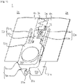
Fig. 1] Fig. 1 is a schematic perspective view of a rear end of closed slide fastener of an aspect of the present disclosure. Illustration of slider is omitted as being located frontward away from the rear end of slide fastener. - [
Fig. 2] Fig. 2 is a schematic top-side elevation of a rear end of closed slide fastener of an aspect of the present disclosure. - [
Fig. 3] Fig. 3 is a schematic cross-sectional view of a stop of an aspect of the present disclosure, illustrating that each one of stop parts stacked in up-down direction has a magnetic body, an encapsulating member, and an injection-molded portion. - [
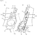
Fig. 4] Fig. 4 is a schematic perspective view of rear end of slide fastener in separated condition of an aspect of the present disclosure. - [
Fig. 5] Fig. 5 is a schematic top-side elevation of rear end of slide fastener in separated condition of an aspect of the present disclosure. Slider is held by a left-side stop part. - [
Fig. 6] Fig. 6 is a schematic perspective view of a left-side stop part of an aspect of the present disclosure. - [
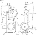
Fig. 7] Fig. 7 is a schematic perspective view of a left-side stop part of an aspect of the present disclosure. Slider is held by the left-side stop part. - [
Fig. 8] Fig. 8 is a schematic perspective view of an encapsulating member of right-side stop part of an aspect of the present disclosure. - [
Fig. 9] Fig. 9 is a schematic side elevation of an encapsulating member of right-side stop part of an aspect of the present disclosure. - [
Fig. 10] Fig. 10 is a schematic perspective view of an encapsulating member of left-side stop part of an aspect of the present disclosure. - [
Fig. 11] Fig. 11 is a schematic side elevation of an encapsulating member of left-side stop part of an aspect of the present disclosure. - [
Fig. 12] Fig. 12 is a schematic illustration illustrating that, in a slide fastener of an aspect of the present disclosure, an insertion portion of right-side stop part is automatically inserted into a slider in accordance with magnetic attraction effected between magnetic bodies of left-side and right-side stop parts. - [
Fig. 13] Fig. 13 is a flowchart of steps for producing a fastener stringer of an aspect of the present disclosure. - [
Fig. 14] Fig. 14 is a schematic illustration of production process of fastener stringer of an aspect of the present disclosure. - [
Fig. 15] Fig. 15 is a schematic cross-sectional view of an embodiment where a cup-like portion and a lid are not mated. - [
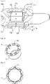
Fig. 16] Fig. 16 is a schematic perspective view of a variant cup-like portion included in an encapsulating member. - [
Fig. 17] Fig. 17 is a schematic perspective view showing a variant lid in encapsulating member. - [
Fig. 18] Fig. 18 is a schematic perspective view showing a variant of a cup-like portion in encapsulating member. - [
Fig. 19] Fig. 19 is a schematic perspective view showing a variant lid in encapsulating member. - [
Fig. 20] Fig. 20 is a schematic cross-sectional view of a variant where an encapsulating member provides one or more functions (e.g. a sloped surface, a sliding portion, or an insertion portion inserted into a slider) of a stop. - Hereinafter, various embodiments and features will be discussed with reference to
Figs. 1 to 20 . Skilled person could combine respective embodiments and or respective features without requiring excess descriptions and could appreciate synergic effects of such combinations. Overlapping descriptions between embodiments would be basically omitted. Referenced drawings are prepared for a purpose of illustration of invention and are simplified for ease of preparation of drawings. Respective features would be appreciated as generic features which are not only effective to fastener stringers and methods of producing the same disclosed in the present specification but also effective to other various fastener stringers and methods for producing the same not disclosed in the present specification. - Hereinafter, Front-rear direction would be understood based on the movement direction of slider in which frontward movement of slider closes a slide fastener and rearward movement of slider opens a slide fastener. Left-right direction and Up-down direction are orthogonal to the front-rear direction. Left-right direction is a parallel direction relative to a tape surface of fastener tape. Up-down direction is a vertical direction relative to a tape surface of fastener tape. Terms indicating these directions can be redefined in light of the following descriptions.
-
Slide fastener 1 has a pair of left andright fastener stringers slider 90 adapted for engaging and disengaging the pair of left andright fastener stringers - The right-
side fastener stringer 2m has a right-side fastener tape 4m provided with a right-side fastener element(s) 3m, and a right-side stop part 5m arranged at an end of the right-side fastener tape 4m. The left-side fastener stringer 2n has a left-side fastener tape 4n provided with a left-side fastener element(s) 3n, and a left-side stop part 5n arranged at an end of the left-side fastener tape 4n. The right and left stopparts - As would be understood from
Figs. 5 and7 , the left-side fastener elements 3n have been inserted through theslider 90, and the left-side stop part 5n prevents theslider 90 from being separated off/from the left-side fastener element 3n. Embodiments are envisaged where the right-side fastener elements 3m are inserted through theslider 90, and the right-side stop part 5m prevents the removal of theslider 90. Theslider 90 has atop wing 91, abottom wing 92, acoupling pillar 93 by which the top andbottom wings flanges 94 situated at the left and right edges of the top andbottom wings slider 90 has a pair of left and rightfront mouths 97, arranged at the left and right sides of thecoupling pillar 93, arear mouth 98 and in turn, a Y-shaped element passage. The fastener tape is inserted into a slit between theflanges 94 of the top andbottom wings slider 90 may be formed from resin or metal or other material. - As illustrated in
Fig. 3 , the right-side stop part 5m includes amagnetic body 30m, an encapsulatingmember 40m encapsulating themagnetic body 30m, and an injection-moldedportion 50m that at least partially covers or surrounds the encapsulatingmember 40m encapsulating themagnetic body 30m. Similarly, the left-side stop part 5n includes amagnetic body 30n, an encapsulatingmember 40n encapsulating themagnetic body 30n, and an injection-moldedportion 50n that at least partially covers or surrounds the encapsulatingmember 40n encapsulating themagnetic body 30n. - The magnetic body may be, for example, a permanent magnet (e.g. rare-earth magnet such as neodymium magnet) or a metal attractable to a permanent magnet, or the like. In some cases, the magnetic body may be coated (e.g. nickel-plated, chrome-plated, epoxy-coated, nylon-coated and the like) for a purpose of avoiding or suppressing corrosion or demagnetization. If required, yokes 39m and 39n may be encapsulated in the encapsulating
members yoke members magnetic body - The encapsulating member is configured to encapsulate the magnetic body, and hinders the injection-molded portion from directly touching the magnetic body. The encapsulating member may be formed of magnetic permeable material. Typically, the encapsulating member is made of resin and produced through injection-molding. In some cases, a heat-insulating layer is formed between the encapsulating member and the magnetic body. The heat-insulating layer may typically be an air-layer but should not be limited to this. Fluid with lower thermal conductivity (powder or liquid or combination thereof) may be injected into an interspace between the encapsulating member and the magnetic body.
- The encapsulating member may be configured from two or more parts which can be coupled together. In the illustrated embodiment, the encapsulating member has a cup-
like portion 45 as a first member and alid 46 as a second member. The cup-like portion 45 has an inlet through which the magnetic body is received. The magnetic body enters into the cup-like portion 45 via the inlet and then, thelid 46 is placed on the cup-like portion 45 to close the inlet. In such a way, the entirety of the magnetic body is encapsulated by the cup-like portion 45 and thelid 46. - The cup-
like portion 45 and thelid 46 may be mechanically coupled e.g. through mating or press-fitting. Accordingly, the encapsulating member can maintain its closed state despite the pressure from the fluid flowing into a mold-cavity during injection-molding. In the illustrated case ofFig. 3 , an annular protrusion is formed on the top surface around the inlet of the cup-like portion 45 (45m, 45n), and this is press-fitted with an outer circumferential wall of the lid 46 (46m, 46n) which extends downward. Additionally or alternatively, the cup-like portion 45 (45m, 45n) and the lid 46 (46m, 46n) may be secured via adhesive. The encapsulating member may be configured from three or more parts. - The injection-molded portion at least partially covers or surrounds the encapsulating member encapsulating the magnetic body. The injection-molded portion is formed through supplying melted material into a mold-cavity in which the encapsulating member encapsulating the magnetic body has been placed. The encapsulating member hinders the melted material from directly touching the magnetic body so that demagnetization of the magnetic body is avoided or suppressed. The injection-molded portion seals the cup-
like portion 45 and the lid 46 (i.e. the first and second members), facilitating strengthened coupling of the two members, not necessarily limited to this though. In other words, the injection-molded portion covers or surrounds the encapsulating member in a manner to seal a boundary between the cup-like portion 45 and thelid 46. - As would be understood from the above descriptions, in the present embodiment, the injection molding allows integration of the magnetic body in the stop part and demagnetization of the magnetic body is avoided or suppressed by the employment of the encapsulating member. Performing the injection molding while avoiding the demagnetization allows integration of the magnetic body in the stop part and minimized possibility of dropping/falling thereof, and thus stop parts for long-term use and with higher durability can be supplied. Note that any type of magnetic body can be used, but neodymium magnet may be employed preferably. The neodymium magnets have a relatively higher magnetic attraction and demagnetization thereof at room temperature is relatively moderate, and thus may be suitable for long-term use.
- The magnetic body may be embedded in one or both of the left and right stop parts. In a case where the magnetic body is embedded in the respective ones of the left and right stop parts as in the illustrated case, the left-side stop part and the right-side stop part will be attracted and both will be stacked. Optionally, additionally to this, rotation of the right-side stop part relative to the left-side stop part may be caused, or rotation of the left-side stop part relative to the right-side stop part may be caused. The rotation of the right-side stop part relative to the left-side stop part may allow insertion of an insertion portion of the right-side stop part into a slider held by the left-side stop part. One may understand a case similarly where the left-side stop part rotates relative to the right-side stop part. This may allow simplified operation required for closing the slide fastener. Slide fasteners can be supplied which are friendly for infants and care-receivers who find difficulty in opening and closing slide fasteners.
- The encapsulating member may have an exposed surface that is exposed from the injection-molded portion. In the illustrated case, the exposed surface of the encapsulating
member 40n includes side and bottom faces of the cup-like portion 45 which are not covered by the injection-moldedportion 50n. The exposed surface of the encapsulatingmember 40m includes a top face of thelid 46 which is not covered by the injection-moldedportion 50m. The bottom face of the cup-like portion 45 of the encapsulatingmember 40n and the top face of thelid 46 of the encapsulatingmember 40m are opposed or contacting faces when themagnetic bodies member 40n (the cup-like portion 45n) is placed directly above the encapsulatingmember 40m (thelid 46m) when the left-side stop part 5n is stacked onto the right-side stop part 5m as shown inFig. 3 . The injection-moldedportions magnetic body 30m and themagnetic body 30n, thus facilitating strengthened magnetic attraction between themagnetic bodies - Although not necessarily limited to this, the injection-molded portion may be shaped to hinder the encapsulating member from being separated (dropping) from the injection-molded portion and in other words, the injection-molded portion may have an undercut that hinders the encapsulating member from being separated from the injection-molded portion. As shown in
Fig. 3 , in the right-side stop part 5m, the injection-moldedportion 50m has: an outer peripheral portion 50m1 arranged circumferentially around the encapsulatingmember 40m; a foundation portion 50m2 that extends radially inward from the bottom end of the outer peripheral portion 50m1 to cover at least partially the bottom face of the encapsulatingmember 40m; and an undercut 50m3 that extends radially inward from the outer peripheral portion 50m1 at a position above the encapsulatingmember 40m. The encapsulatingmember 40m is sandwiched between the foundation portion 50m2 and the undercut 50m3, preventing the encapsulatingmember 40m from being separated from the injection-moldedportion 50m. The boundary between the cup-like portion 45 and thelid 46 may be sealed by the outer peripheral portion 50m1. In the illustrated case ofFig. 3 , the cup-like portion 45 is positioned at lower side and thelid 46 is positioned at upper side, and thus the undercut 50m3 touches thelid 46. Embodiments are envisaged where the cup-like portion 45 is positioned at upper side and thelid 46 is positioned at lower side, and the undercut 50m3 touches the cup-like portion 45. - In the left-
side stop part 5n, the injection-moldedportion 50n has: an outer peripheral portion 50n1 arranged circumferentially around the encapsulatingmember 40n; a foundation portion 50n2 that extends radially inward from a top end of the outer peripheral portion 50n1 to at least partially cover the top face of the encapsulatingmember 40n; and an undercut 50n3 that extends radially inward from the outer peripheral portion 50n1 of the encapsulatingmember 40n. The cup-like portion 45f has a diameter that decreases downward, and the inner circumference face of the undercut 50n3 of the injection-moldedportion 50n has a diameter that increases upward. Owing to this, the encapsulatingmember 40n is prevented from being separated from the injection-moldedportion 50n. The boundary between the cup-like portion 45 and thelid 46 may be sealed by the outer peripheral portion 50n1. In the illustrated case ofFig. 3 , the cup-like portion 45 is positioned under thelid 46 and the undercut 50n3 touches the cup-like portion 45. However, embodiments are envisaged where the cup-like portion 45 is positioned above thelid 46, and the undercut 50n3 touches thelid 46. - The injection-molded portion may be shaped such that, alone or together with the encapsulating member, various functions are embodied in the stop part. In a non-limiting example, the stop part is configured to allow the right-side stop part to rotate relative to the left-side stop part or to allow the left-side stop part to rotate to the right-side stop part. The left and
right stop parts base member portion base insertion portion slider 90. - The extending
portion 52n of the left-side stop part 5n hasinsertion portion 53n and guidingbar 54n which extend frontward from thebase 51n. Theinsertion portion 53n is inserted into theslider 90 via therear mouth 98 of theslider 90. Theinsertion portion 53n is inserted into theslider 90, and theslider 90 is held by theinsertion portion 53n. Left-side flange 94 of the top orbottom wing insertion portion 53n and the guidingbar 54n. Left-side fastener tape 4n may be exposed between theinsertion portion 53n and the guidingbar 54n, or a region between theinsertion portion 53n and the guidingbar 54n is covered by a thin layer of injection-molded portion. Theinsertion portion 53n of the extendingportion 52n is configured to receive theinsertion portion 53m of right-side stop part 5m when theslide fastener 1 is closed. - The extending
portion 52m of the right-side stop part 5m hasinsertion portion 53m and stoppingbar 54m which extend frontward from thebase 51m.Dummy element 55 sits at the front end of the extendingportion 52m adjacent to the right-side fastener element 3m. Theinsertion portion 53m is inserted into theslider 90 via a slit between right-side upper andlower flanges 94 of theslider 90. The stoppingbar 54m abuts against theflange 94 of theslider 90, thus defining a stop position for theinsertion portion 53m pivoting towards the coupling pillar of theslider 90. Theslider 90 moves frontward after theinsertion portion 53m is inserted into theslider 90 so that theinsertion portion 53n receives theinsertion portion 53m and the left and right stopparts parts - In the
base 51n of the left-side stop part 5n, the encapsulatingmember 40n protrudes downward from the outer peripheral portion 50n1. Themagnetic body 30n in the encapsulatingmember 40n has a thickness in the up-down direction greater than the thickness of themagnetic body 30m, and thus can form the magnetic field farther along the axis AX2 shown inFig. 4 . In contrast, themagnetic body 30m in the encapsulatingmember 40m has a width (i.e. radius) in a direction orthogonal to the up-down direction which is greater than the width (i.e. radius) of themagnetic body 30n, and thus can form the magnetic field farther along the radial direction directed radially outward from the axis AX1 shown inFig. 4 . - The encapsulating
member 40m is configured to encapsulate themagnetic body 30m having a thinner thickness in the up-down direction and in more detail, is configured from a cup-like portion 45m and alid 46m as illustrated inFigs. 3 ,8 and 9 . The encapsulatingmember 40n is configured to encapsulate themagnetic body 30n having a thicker thickness in the up-down direction and in more detail, is configured from a cup-like portion 45n and alid 46n as illustrated inFigs. 3 ,10 and 11 . The depth and capacity of the cup-like portion 45n are greater than the depth and capacity of the cup-like portion 45m. In thebase 51n of the left-side stop part 5n, the cup-like portion 45n protrudes downward from the outer peripheral portion 50n1. It could be said that the encapsulatingmember 40n has a truncated-cone-like portion with its side face partially covered by the injection-moldedportion 50n. In the base 51m of the right-side stop part 5m, the top face of thelid 46m is exposed and is opposed to the bottom face of the cup-like portion 45n. The top face of thelid 46m is a flat surface partially covered by the injection-moldedportion 50m. - As illustrated in
Figs. 4 and5 , the injection-moldedportion 50m of the right-side stop part 5m is configured to receive the encapsulatingmember 40n of the left-side stop part 5n, i.e. the truncated-cone-like portion of the cup-like portion 45. The undercut 50m3 extends along the periphery of the encapsulatingmember 40m, thus defining an accommodating space. There is no need for the undercut to be in continuous in the circumferential direction. Embodiments are envisaged where plural undercuts are arranged in the circumferential direction. The injection-moldedportion 50m has at least onesloped surface 56 that approaches the encapsulatingmember 40m (the top face of the lid 46) as extending along the circumferential direction about the axis AX1 on which N-pole and S-pole of themagnetic body 30m are aligned. - The sloped
surface 56 is arranged radially outward from the axis AX1 with respect to themagnetic body 30m, i.e. arranged in the outer peripheral portion 50m1 and/or the undercut 50m3 of the injection-moldedportion 50m. The slopedsurface 56 is formed partially in the circumferential direction, e.g. with a length equal to or within 180° or 150° or 90° of the total angular range 360° about the axis AX1. Therefore, even if the undercut 50m3 is thinned due to the slopedsurface 56, the undercut 50m3 can sufficiently suppress the separation of the encapsulatingmember 40m from the injection-moldedportion 50m. - As illustrated in
Figs. 6 and 7 , the injection-moldedportion 50n of the left-side stop part 5n is configured to have at least one slidingportion 57 that slides on the slopedsurface 56 in accordance with magnetic attraction effected between themagnetic bodies portion 57 is arranged radially outward from the axis AX2 with respect to themagnetic body 30n, i.e. arranged radially outward of the truncated-cone-like portion with respect to the axis AX2. The slidingportion 57 is arranged in the outer peripheral portion 50n1 and/or the undercut 50n3 of the injection-moldedportion 50n. The slidingportion 57 is an edge between aflat surface 57p and avertical surface 57q but should not be limited to this. - When the left and right stop
parts magnetic bodies portion 57 touches the slopedsurface 56 and descends the slopedsurface 56. In this process, as illustrated inFig. 12 , the right-side stop part 5m rotates relative to the left-side stop part 5n, and theinsertion portion 53m of the right-side stop part 5m is inserted into theslider 90 via the slit between the right-side upper andlower flanges 94 of theslider 90. Embodiments are envisaged where, during a period the slidingportion 57 descends the slopedsurface 56, the number of contact points between thebases - Note that, as illustrated in
Figs. 6 and 7 , the injection-moldedportion 50n of the left-side stop part 5n includes awall 86 arranged to form agroove 85 between thewall 86 and the encapsulatingmember 40n (i.e. the truncated-cone-like portion of the cup-like portion 45). Thewall 86 has a descending slopedsurface 87 that descends in the circumferential direction with respect to the axis AX2. The downstream end of the descending slopedsurface 87 protrudes in the left-right direction than the rear end of theslider 90. A slot 88 is formed between thewall 86 and the outer peripheral portion 50n1. The slot 88 is in spatial communication with the accommodating space of theinsertion portion 53n of the left-side stop part 5n. When theinsertion portion 53m of the right-side stop part 5m is placed on the descending slopedsurface 87, theinsertion portion 53m descends the descending slopedsurface 87 in accordance with the magnetic attraction effected between themagnetic bodies slider 90 and the slot 88 without significantly interfering with theslider 90. - Non-limiting methods of producing the above-described fastener stringers will be described with reference to
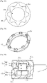
Figs. 13 and 14 . Firstly, the magnetic body is encapsulated in the encapsulating member (SI). The encapsulating member can be produced through injection-molding in advance. In more detail, the magnetic body is placed inside of the cup-like portion, and then the inlet of the cup-like portion is closed by the lid. Note that, encapsulating the magnetic body in the encapsulating member can be performed by human or robot or corporation of the both. The operation of encapsulating the magnetic body in the encapsulating member can be performed at any location, but can be performed on a mold device described below, e.g. a fixed mold. - Next, injection molding is performed while at least the encapsulating member and the fastener tape are placed in a mold-cavity of a mold device (S2). As illustrated in
Fig. 14 , the mold device may have a fixedmold 200a and amovable mold 200b. The fixedmold 200a and themovable mold 200b have cavity-surfaces cavity 201. The encapsulating member can be placed at a predetermined location on thecavity surface 202a of the fixedmold 200a while themovable mold 200b is positioned away from the fixedmold 200a. For a purpose of appropriate alignment of the encapsulatingmember 40 on the fixedmold 200a, the fixedmold 200a may be provided with amagnet 210 for alignment. Themagnetic body 30 inside the encapsulatingmember 40 is attracted by themagnet 210 for alignment so that appropriate alignment is ensured. Note that, in the fixedmold 200a and themovable mold 200b,surfaces accommodating spaces - The melted material, e.g. melted resin to be supplied into the mold-
cavity 201 of the mold device may be supplied into the mold-cavity 201 through a sprue, a runner and a gate not illustrated. The melted resin, having been supplied into the mold-cavity 201, reaches and touches the encapsulatingmember 40, but does not directly touch the magnetic body as being hindered by the encapsulatingmember 40 so that demagnetization of the magnetic body is avoided or suppressed. Once the mold-cavity 201 is filled with the melted resin, themold device 200 is cooled and the resin inside the mold-cavity 201 is hardened so that the injection-molded portion is molded. Injection molding for the injection-moldedportion 50m of the right-side stop part 5m should be similarly appreciated. -
Fig. 15 discloses an embodiment where the cup-like portion and the lid are not mated. Embodiments are envisaged where the lid is placed onto the top face positioned circumferentially around the inlet of the cup-like portion and is fixed thereto via an adhesive.Fig. 16 illustrates an embodiment where the cup-like portion 45 and thelid 46 are mated. The cup-like portion 45 has aninlet 45t for receiving the magnetic body, and a plurality ofprotrusions 45r arranged along a periphery of theinlet 45t. As shown inFig. 17 , thelid 46 hasrecesses 46s to be mated with theprotrusions 45r respectively. The number of theprotrusion 45r and therecess 46s should not be limited to 8 as illustrated, but may be equal to or greater than 1, preferably equal to or greater than 2 or 3 or 4. As illustrated inFig. 18 , embodiments are envisaged where onerecess 45s is provided which is continuous in the circumferential direction of the cup-like portion 45.Fig. 19 illustrates alid 46 with a plurality ofprotrusions 46r to be mated with therecess 45s ofFig. 18 . - As noted above, the injection-molded portion may be shaped such that, alone or together with the encapsulating member, various functions are embodied in the stop part. Functions to be allocated to the injection-molded portion and to be allocated to the encapsulating member would be determined in view of specific requirements (customer demand, efficiency of manufacturing, ease of design). Therefore, embodiments are envisaged as a matter of course where the above-described
sloped surface 56 or the slidingportion 57 is formed in the encapsulating member instead of the injection-molded portion.Fig. 20 clarifies this point and shows a variant where the encapsulating member provides one or more functions of the stop part (e.g. the sloped surface, the sliding portion, the insertion portion to be inserted into the slider). In the right-side stop part 5m, the injection-moldedportion 50m is formed below the encapsulatingmember 40m. In the left-side stop part 5n, the injection-moldedportion 50n is formed above the encapsulatingmember 40n. - The encapsulating
member 40m has a recess for accommodating themagnetic body 30m; the sloped surface 56 (optional); amain body 47m provided with the insertion portion (optional); and alid 46m coupled to themain body 47m for confining themagnetic body 30m in the recess. Embodiments are envisaged where themain body 47m is fixed to the fastener tape in advance before forming the injection-moldedportion 50m, but should not be limited to this. Similarly, the encapsulatingmember 40n has a recess for accommodating themagnetic body 30n; a sliding portion 57 (optional); amain body 47n provided with the insertion portion (optional); and alid 46n coupled to themain body 47n for confining themagnetic body 30n in the recess. Embodiments are envisaged where themain body 47n is fixed to the fastener tape in advance before forming the injection-moldedportion 50n, but should not be limited to this. - A skilled person in the art would be able to add various modifications to the respective embodiments based on the above teachings. Reference codes in Claims are added just for a purpose of reference and should not be referred to for narrowly construing the scope of Claim.
-
- 1: Slide fastener
- 2m, 2n: Fastener stringer
- 3m, 3n: Fastener element
- 4m, 4n: Right-side fastener tape
- 90: Slider
- 5m, 5n: Stop part
- 30m, 30n: Magnetic body
- 40m, 40n: Encapsulating member
- 46m, 46n: Lid
- 50m, 50n: Injection-molded portion
- 200: Mold
Claims (17)
- A fastener stringer (2n,2m) comprising:a fastener tape (4n,4m) provided with a fastener element (3n,3m); anda stop part (5n,5m) arranged at an end of the fastener tape (4n,4m), whereinthe stop part (5n,5m) includes:a magnetic body (30n,30m);an encapsulating member (40n,40m) encapsulating the magnetic body (30n,30m); andan injection-molded portion (50n,50m) that at least partially covers or surrounds the encapsulating member (40n,40m) encapsulating the magnetic body (30n,30m), and whereinat least the encapsulating member (40n,40m) hinders heat from being transferred to the magnetic body (30n,30m) while the injection-molded portion (50n,50m) is formed.
- The fastener stringer of Claim 1, wherein a heat-insulating layer is formed between the encapsulating member (40n,40m) and the magnetic body (30n,30m).
- The fastener stringer of Claim 1 or 2, wherein the encapsulating member (40n,40m) has an exposed surface that is exposed from the injection-molded portion (50n,50m).
- The fastener stringer of any one of Claims 1 to 3, wherein the injection-molded portion (50n,50m) is shaped to hinder the encapsulating member (40n,40m) from being separated from the injection-molded portion (50n,50m).
- The fastener stringer of any one of Claims 1 to 4, wherein the injection-molded portion (50n,50m) comprises an outer peripheral portion (50m1,50n1) arranged circumferentially around the encapsulating member (40n,40m) and an undercut (53n,53m) extending or protruding radially inward from the outer peripheral portion (50m1,50n1).
- The fastener stringer of any one of Claims 1 to 5, wherein the encapsulating member (40n,40m) includes at least first and second members (45m,45n,46m,46n,47m,47n), a boundary between the first and second members (45m,45n,46m,46n,47m,47n) being sealed by the injection-molded portion (50n,50m).
- The fastener stringer of Claim 6, wherein one of the first and second members (45m,45n,46m,46n) is a cup-like portion (45m,45n) having an inlet through which the magnetic body (30n,30m) is received, and the other one of the first and second members (45m,45n,46m,46n) is a lid (46m,46n) that closes the inlet of the cup-like portion (45m,45n).
- The fastener stringer of Claim 6, wherein one of the first and second members (45m,45n,46m,46n) comprises an inlet through which the magnetic body (30n,30m) is received and one or more protrusions (45r,46r) arranged along a periphery of the inlet, and the other one of the first and second members (45m,45n,46m,46n) comprises one or more recesses (45s,46s) mated with the one or more protrusions.
- The fastener stringer of any one of Claims 1 to 8, wherein the encapsulating member (40n,40m) comprises (i) a truncated-cone-like portion having a side face partially covered by the injection-molded portion (50n,50m) or (ii) a flat surface partially covered by the injection-molded portion (50n,50m).
- The fastener stringer of any one of Claims 1 to 9, wherein the injection-molded portion (50n,50m) comprises:a base (51n,51m) including the encapsulating member (40n,40m); andan extending portion (52n,52m) extending from the base (51n,51m) so as to have an insertion portion (53m,53n) that is to be inserted into a slider.
- The fastener stringer of Claim 10, wherein the base (51m) comprises at least one sloped surface (56) that approaches the encapsulating member (40m) as extending along a circumferential direction about an axis (AX1) on which N-pole and S-pole of the magnetic body (30m) are aligned, the sloped surface (56) being positioned over the encapsulating member (40m) at least partially.
- The fastener stringer of Claim 10, wherein the encapsulating member (40n) includes a truncated-cone-like portion with its side face partially covered by the injection-molded portion (50n), and the base (51n) comprises at least one sliding portion (57) arranged radially outward of the truncated-cone-like portion with respect to an axis (AX2) on which N-pole and S-pole of the magnetic body (30n) are aligned.
- The fastener stringer of any one of Claims 1-12, wherein the magnetic body (30n,30m) is a neodymium magnet.
- A slide fastener (1) comprising:first and second fastener stringers (2m,2n), the first fastener stringer (2m) including a first fastener tape (4m) provided with a first fastener element (3m), and a first stop part (5m) provided at an end of the first fastener tape (4m), and the second fastener stringer (2n) including a second fastener tape (4n) provided with a second fastener element (3n), and a second stop part (5n) provided at an end of the second fastener tape (4n) and adapted to configure a stop together with the first stop part (5m); anda slider (5) adapted for engaging and disengaging the first and second fastener stringers (2m,2n), whereinthe first stop part (5m) includes a first magnetic body (30m), a first encapsulating member (40m) encapsulating the first magnetic body (30m), a first injection-molded portion (50m) that at least partially covers or surrounds the first encapsulating member (40m) encapsulating the first magnetic body (30m), and at least one sloped surface (56) that approaches the first encapsulating member (40m) as extending along a circumferential direction about an axis (AX1) on which N-pole and S-pole of the first magnetic body (30m) are aligned, and whereinthe second stop part (5n) includes a second magnetic body (30n), a second encapsulating member (40n) encapsulating the second magnetic body (30n), a second injection-molded portion (50n) that at least partially covers or surrounds the second encapsulating member (40n) encapsulating the second magnetic body (30n), and at least one sliding portion (57) that slides on the sloped surface (56) in accordance with magnetic attraction effected between the first and second magnetic bodies (30m,30n).
- The slide fastener of Claim 14, whereinthe first encapsulating member (40m) has a flat surface partially covered by the injection-molded portion, and the sloped surface (56) is at least partially formed over the flat surface,the second encapsulating member (40n) has a truncated-cone-like portion with its side face partially covered by the injection-molded portion (50n), and the sliding portion (57) is arranged radially outward of the truncated-cone-like portion with respect to an axis (AX2) along which N-pole and S-pole of the second magnetic body (30n) are aligned.
- The slide fastener of Claim 14 or 15, wherein at least one of the first and second encapsulating members (40n,40m) includes a cup-like portion (45m,45n) having an inlet through which the magnetic body is received, and a lid (46m,46n) that closes the inlet of the cup-like portion (45m,45n).
- A method of producing a fastener stringer that comprises a fastener tape (4n,4m) provided with a fastener element (3n,3m), and a stop part (5n,5m) arranged at an end of the fastener tape (4n,4m), the method comprising:encapsulating a magnetic body (30n,30m) in an encapsulating member (40n,40m); andperforming injection-molding in a condition where the encapsulating member (40n,40m), by which the magnetic body (30n,30m) is encapsulated, and a portion of the fastener tape (4n,4m) are arranged in a mold-cavity of a mold, whereinat least the encapsulating member (40n,40m) hinders heat from being transferred to the magnetic body (30n,30m) during the injection molding.
Applications Claiming Priority (1)
| Application Number | Priority Date | Filing Date | Title |
|---|---|---|---|
| PCT/JP2019/035588 WO2021048930A1 (en) | 2019-09-10 | 2019-09-10 | Fastener stringer, method for manufacturing same, and slide fastener |
Publications (3)
| Publication Number | Publication Date |
|---|---|
| EP4029399A1 true EP4029399A1 (en) | 2022-07-20 |
| EP4029399A4 EP4029399A4 (en) | 2022-12-21 |
| EP4029399B1 EP4029399B1 (en) | 2023-10-25 |
Family
ID=74866296
Family Applications (1)
| Application Number | Title | Priority Date | Filing Date |
|---|---|---|---|
| EP19944990.1A Active EP4029399B1 (en) | 2019-09-10 | 2019-09-10 | Fastener stringer and method for manufacturing same |
Country Status (6)
| Country | Link |
|---|---|
| US (1) | US11627784B2 (en) |
| EP (1) | EP4029399B1 (en) |
| JP (1) | JP7133720B2 (en) |
| CN (1) | CN114096175B (en) |
| TW (1) | TWI728693B (en) |
| WO (1) | WO2021048930A1 (en) |
Cited By (1)
| Publication number | Priority date | Publication date | Assignee | Title |
|---|---|---|---|---|
| EP3766371A4 (en) * | 2018-03-12 | 2021-11-03 | YKK Corporation | STOP AND ZIPPER ELEMENT INCLUDING IT |
Families Citing this family (7)
| Publication number | Priority date | Publication date | Assignee | Title |
|---|---|---|---|---|
| WO2021095139A1 (en) * | 2019-11-12 | 2021-05-20 | Ykk株式会社 | Slide fastener |
| CN116471957B (en) * | 2020-12-24 | 2025-10-28 | Ykk株式会社 | Zipper chain tape, zipper, stopper component and method for manufacturing zipper |
| CN218418702U (en) * | 2022-08-22 | 2023-02-03 | 浙江伟星实业发展股份有限公司 | Zipper bottom stop and zipper |
| JP1755524S (en) * | 2022-11-04 | 2023-10-18 | Chain for slide fasteners | |
| USD1088955S1 (en) * | 2023-04-13 | 2025-08-19 | Ykk Corporation | Chain for slide fastener |
| US20240423332A1 (en) * | 2023-06-20 | 2024-12-26 | Nike, Inc. | Fastening assembly for a closure mechanism |
| CN117301420B (en) * | 2023-11-03 | 2026-02-24 | 威海双翼环保科技有限公司 | Manufacturing process of magnetic zipper |
Family Cites Families (16)
| Publication number | Priority date | Publication date | Assignee | Title |
|---|---|---|---|---|
| JP4152216B2 (en) | 2003-02-19 | 2008-09-17 | Ykk株式会社 | Separation insert for slide fastener |
| JP4464802B2 (en) * | 2004-11-30 | 2010-05-19 | Ykk株式会社 | fastener |
| KR200394484Y1 (en) * | 2005-06-10 | 2005-08-31 | (주)마그넷포유 | Polyhedron type magnetic toys |
| JP4395785B2 (en) * | 2006-02-27 | 2010-01-13 | 芳江 外丸 | Completely separate magnet slide fastener. |
| US8146214B2 (en) * | 2009-06-15 | 2012-04-03 | Dns Designs, Llc | Zipper |
| JP5454900B2 (en) * | 2010-02-10 | 2014-03-26 | 積水樹脂株式会社 | Resin-coated long body |
| JP5414895B2 (en) * | 2010-06-23 | 2014-02-12 | Ykk株式会社 | Slide fastener |
| JP3170902U (en) | 2011-07-25 | 2011-10-06 | Ykk株式会社 | Separation fitting insert for slide fastener and slide fastener |
| US9027210B2 (en) * | 2011-09-12 | 2015-05-12 | Dns Designs, Llc | Self-aligning zipper |
| KR101448107B1 (en) * | 2013-07-01 | 2014-10-13 | 양민우 | Tie a magnet coupled |
| CN204032535U (en) | 2014-09-15 | 2014-12-24 | 徐飞 | A kind of magnet zipper |
| WO2016114456A1 (en) | 2015-01-12 | 2016-07-21 | 주식회사 케이엠케이 | Slide fastener |
| WO2018061208A1 (en) * | 2016-09-30 | 2018-04-05 | Ykk株式会社 | Rotation mechanism of separable stopper for slide fastener and slide fastener including same |
| WO2019064355A1 (en) * | 2017-09-26 | 2019-04-04 | Ykk株式会社 | Slide fastener |
| US11425972B2 (en) | 2018-03-12 | 2022-08-30 | Ykk Corporation | Stopper and slide fastener comprising same |
| US11432622B2 (en) * | 2020-03-17 | 2022-09-06 | Nike, Inc. | Releasable coupling device |
-
2019
- 2019-09-10 EP EP19944990.1A patent/EP4029399B1/en active Active
- 2019-09-10 CN CN201980098260.8A patent/CN114096175B/en active Active
- 2019-09-10 JP JP2021545013A patent/JP7133720B2/en active Active
- 2019-09-10 WO PCT/JP2019/035588 patent/WO2021048930A1/en not_active Ceased
- 2019-09-10 US US17/613,356 patent/US11627784B2/en active Active
-
2020
- 2020-02-12 TW TW109104327A patent/TWI728693B/en active
Cited By (1)
| Publication number | Priority date | Publication date | Assignee | Title |
|---|---|---|---|---|
| EP3766371A4 (en) * | 2018-03-12 | 2021-11-03 | YKK Corporation | STOP AND ZIPPER ELEMENT INCLUDING IT |
Also Published As
| Publication number | Publication date |
|---|---|
| US11627784B2 (en) | 2023-04-18 |
| JPWO2021048930A1 (en) | 2021-03-18 |
| EP4029399A4 (en) | 2022-12-21 |
| WO2021048930A1 (en) | 2021-03-18 |
| CN114096175B (en) | 2023-10-13 |
| TWI728693B (en) | 2021-05-21 |
| CN114096175A (en) | 2022-02-25 |
| EP4029399B1 (en) | 2023-10-25 |
| TW202110356A (en) | 2021-03-16 |
| US20220225740A1 (en) | 2022-07-21 |
| JP7133720B2 (en) | 2022-09-08 |
Similar Documents
| Publication | Publication Date | Title |
|---|---|---|
| EP4029399B1 (en) | Fastener stringer and method for manufacturing same | |
| CN100528027C (en) | Verschluss | |
| EP2654598B1 (en) | Method of making a dispensing device for a dental substance | |
| EP2533372B1 (en) | Connector housing with mat seal | |
| KR20030007672A (en) | Segmented separable fastener | |
| US9055790B2 (en) | Slide fastener | |
| CA2666280C (en) | Nozzle sleeve for an injection molding apparatus | |
| JP6526937B1 (en) | Method of manufacturing seal ring and seal ring | |
| US20130074293A1 (en) | Slide Fastener | |
| CN110690777B (en) | Rotor assembly, method of manufacturing the same, and motor using the same | |
| US20230404222A1 (en) | Fastener stringer, slide fastener, and method for producing stopper component and slide fastener | |
| TW201145376A (en) | Manufacturing method for retainer ring of chemical mechanical polishing apparatus | |
| RU2016103932A (en) | FLUID VALVE CONTAINING SEALING SEALS (OPTIONS) | |
| US10704700B2 (en) | Check valve structure | |
| KR20070110990A (en) | Mold device | |
| EP3220728A1 (en) | Water-proof control unit and manufacturing method for water-proof control unit | |
| CN103402729A (en) | Injection-molding machine | |
| CN106961172A (en) | Magnetic coupled rotor | |
| CN220638717U (en) | Magnetic pull-open tail zipper die | |
| JP2015183714A (en) | Flow control valve | |
| JP2015090183A (en) | Soft sealing gate valve | |
| KR100853338B1 (en) | Method of integrally fastening the fastener tape when forming the foam sheet, and the protector and the fastener tape used therein | |
| CN105626879A (en) | Gas valve and method for manufacturing sealing element | |
| JP2010162769A (en) | Temperature control system for molding die, tape cartridge, and method of molding molded article | |
| HK1135289A (en) | Slide fastener and slider for slide fastener |
Legal Events
| Date | Code | Title | Description |
|---|---|---|---|
| STAA | Information on the status of an ep patent application or granted ep patent |
Free format text: STATUS: THE INTERNATIONAL PUBLICATION HAS BEEN MADE |
|
| PUAI | Public reference made under article 153(3) epc to a published international application that has entered the european phase |
Free format text: ORIGINAL CODE: 0009012 |
|
| STAA | Information on the status of an ep patent application or granted ep patent |
Free format text: STATUS: REQUEST FOR EXAMINATION WAS MADE |
|
| 17P | Request for examination filed |
Effective date: 20211203 |
|
| AK | Designated contracting states |
Kind code of ref document: A1 Designated state(s): AL AT BE BG CH CY CZ DE DK EE ES FI FR GB GR HR HU IE IS IT LI LT LU LV MC MK MT NL NO PL PT RO RS SE SI SK SM TR |
|
| DAV | Request for validation of the european patent (deleted) | ||
| DAX | Request for extension of the european patent (deleted) | ||
| A4 | Supplementary search report drawn up and despatched |
Effective date: 20221122 |
|
| RIC1 | Information provided on ipc code assigned before grant |
Ipc: A44B 19/38 20060101AFI20221116BHEP |
|
| REG | Reference to a national code |
Ref country code: DE Free format text: PREVIOUS MAIN CLASS: A44B0019240000 Ref country code: DE Ref legal event code: R079 Ref document number: 602019040368 Country of ref document: DE Free format text: PREVIOUS MAIN CLASS: A44B0019240000 Ipc: A44B0019380000 |
|
| GRAP | Despatch of communication of intention to grant a patent |
Free format text: ORIGINAL CODE: EPIDOSNIGR1 |
|
| STAA | Information on the status of an ep patent application or granted ep patent |
Free format text: STATUS: GRANT OF PATENT IS INTENDED |
|
| RIC1 | Information provided on ipc code assigned before grant |
Ipc: A44B 19/38 20060101AFI20230509BHEP |
|
| INTG | Intention to grant announced |
Effective date: 20230609 |
|
| GRAS | Grant fee paid |
Free format text: ORIGINAL CODE: EPIDOSNIGR3 |
|
| P01 | Opt-out of the competence of the unified patent court (upc) registered |
Effective date: 20230813 |
|
| GRAA | (expected) grant |
Free format text: ORIGINAL CODE: 0009210 |
|
| STAA | Information on the status of an ep patent application or granted ep patent |
Free format text: STATUS: THE PATENT HAS BEEN GRANTED |
|
| AK | Designated contracting states |
Kind code of ref document: B1 Designated state(s): AL AT BE BG CH CY CZ DE DK EE ES FI FR GB GR HR HU IE IS IT LI LT LU LV MC MK MT NL NO PL PT RO RS SE SI SK SM TR |
|
| REG | Reference to a national code |
Ref country code: GB Ref legal event code: FG4D |
|
| REG | Reference to a national code |
Ref country code: CH Ref legal event code: EP |
|
| REG | Reference to a national code |
Ref country code: DE Ref legal event code: R082 Ref document number: 602019040368 Country of ref document: DE Representative=s name: BOEHMERT & BOEHMERT ANWALTSPARTNERSCHAFT MBB -, DE |
|
| REG | Reference to a national code |
Ref country code: DE Ref legal event code: R096 Ref document number: 602019040368 Country of ref document: DE |
|
| REG | Reference to a national code |
Ref country code: IE Ref legal event code: FG4D |
|
| REG | Reference to a national code |
Ref country code: LT Ref legal event code: MG9D |
|
| REG | Reference to a national code |
Ref country code: NL Ref legal event code: MP Effective date: 20231025 |
|
| REG | Reference to a national code |
Ref country code: AT Ref legal event code: MK05 Ref document number: 1623733 Country of ref document: AT Kind code of ref document: T Effective date: 20231025 |
|
| PG25 | Lapsed in a contracting state [announced via postgrant information from national office to epo] |
Ref country code: NL Free format text: LAPSE BECAUSE OF FAILURE TO SUBMIT A TRANSLATION OF THE DESCRIPTION OR TO PAY THE FEE WITHIN THE PRESCRIBED TIME-LIMIT Effective date: 20231025 |
|
| PG25 | Lapsed in a contracting state [announced via postgrant information from national office to epo] |
Ref country code: GR Free format text: LAPSE BECAUSE OF FAILURE TO SUBMIT A TRANSLATION OF THE DESCRIPTION OR TO PAY THE FEE WITHIN THE PRESCRIBED TIME-LIMIT Effective date: 20240126 |
|
| PG25 | Lapsed in a contracting state [announced via postgrant information from national office to epo] |
Ref country code: IS Free format text: LAPSE BECAUSE OF FAILURE TO SUBMIT A TRANSLATION OF THE DESCRIPTION OR TO PAY THE FEE WITHIN THE PRESCRIBED TIME-LIMIT Effective date: 20240225 |
|
| PG25 | Lapsed in a contracting state [announced via postgrant information from national office to epo] |
Ref country code: LT Free format text: LAPSE BECAUSE OF FAILURE TO SUBMIT A TRANSLATION OF THE DESCRIPTION OR TO PAY THE FEE WITHIN THE PRESCRIBED TIME-LIMIT Effective date: 20231025 |
|
| PG25 | Lapsed in a contracting state [announced via postgrant information from national office to epo] |
Ref country code: AT Free format text: LAPSE BECAUSE OF FAILURE TO SUBMIT A TRANSLATION OF THE DESCRIPTION OR TO PAY THE FEE WITHIN THE PRESCRIBED TIME-LIMIT Effective date: 20231025 |
|
| PG25 | Lapsed in a contracting state [announced via postgrant information from national office to epo] |
Ref country code: ES Free format text: LAPSE BECAUSE OF FAILURE TO SUBMIT A TRANSLATION OF THE DESCRIPTION OR TO PAY THE FEE WITHIN THE PRESCRIBED TIME-LIMIT Effective date: 20231025 |
|
| PG25 | Lapsed in a contracting state [announced via postgrant information from national office to epo] |
Ref country code: LT Free format text: LAPSE BECAUSE OF FAILURE TO SUBMIT A TRANSLATION OF THE DESCRIPTION OR TO PAY THE FEE WITHIN THE PRESCRIBED TIME-LIMIT Effective date: 20231025 Ref country code: IS Free format text: LAPSE BECAUSE OF FAILURE TO SUBMIT A TRANSLATION OF THE DESCRIPTION OR TO PAY THE FEE WITHIN THE PRESCRIBED TIME-LIMIT Effective date: 20240225 Ref country code: GR Free format text: LAPSE BECAUSE OF FAILURE TO SUBMIT A TRANSLATION OF THE DESCRIPTION OR TO PAY THE FEE WITHIN THE PRESCRIBED TIME-LIMIT Effective date: 20240126 Ref country code: ES Free format text: LAPSE BECAUSE OF FAILURE TO SUBMIT A TRANSLATION OF THE DESCRIPTION OR TO PAY THE FEE WITHIN THE PRESCRIBED TIME-LIMIT Effective date: 20231025 Ref country code: BG Free format text: LAPSE BECAUSE OF FAILURE TO SUBMIT A TRANSLATION OF THE DESCRIPTION OR TO PAY THE FEE WITHIN THE PRESCRIBED TIME-LIMIT Effective date: 20240125 Ref country code: AT Free format text: LAPSE BECAUSE OF FAILURE TO SUBMIT A TRANSLATION OF THE DESCRIPTION OR TO PAY THE FEE WITHIN THE PRESCRIBED TIME-LIMIT Effective date: 20231025 Ref country code: PT Free format text: LAPSE BECAUSE OF FAILURE TO SUBMIT A TRANSLATION OF THE DESCRIPTION OR TO PAY THE FEE WITHIN THE PRESCRIBED TIME-LIMIT Effective date: 20240226 |
|
| PG25 | Lapsed in a contracting state [announced via postgrant information from national office to epo] |
Ref country code: SE Free format text: LAPSE BECAUSE OF FAILURE TO SUBMIT A TRANSLATION OF THE DESCRIPTION OR TO PAY THE FEE WITHIN THE PRESCRIBED TIME-LIMIT Effective date: 20231025 Ref country code: RS Free format text: LAPSE BECAUSE OF FAILURE TO SUBMIT A TRANSLATION OF THE DESCRIPTION OR TO PAY THE FEE WITHIN THE PRESCRIBED TIME-LIMIT Effective date: 20231025 Ref country code: PL Free format text: LAPSE BECAUSE OF FAILURE TO SUBMIT A TRANSLATION OF THE DESCRIPTION OR TO PAY THE FEE WITHIN THE PRESCRIBED TIME-LIMIT Effective date: 20231025 Ref country code: NO Free format text: LAPSE BECAUSE OF FAILURE TO SUBMIT A TRANSLATION OF THE DESCRIPTION OR TO PAY THE FEE WITHIN THE PRESCRIBED TIME-LIMIT Effective date: 20240125 Ref country code: LV Free format text: LAPSE BECAUSE OF FAILURE TO SUBMIT A TRANSLATION OF THE DESCRIPTION OR TO PAY THE FEE WITHIN THE PRESCRIBED TIME-LIMIT Effective date: 20231025 Ref country code: HR Free format text: LAPSE BECAUSE OF FAILURE TO SUBMIT A TRANSLATION OF THE DESCRIPTION OR TO PAY THE FEE WITHIN THE PRESCRIBED TIME-LIMIT Effective date: 20231025 |
|
| PG25 | Lapsed in a contracting state [announced via postgrant information from national office to epo] |
Ref country code: DK Free format text: LAPSE BECAUSE OF FAILURE TO SUBMIT A TRANSLATION OF THE DESCRIPTION OR TO PAY THE FEE WITHIN THE PRESCRIBED TIME-LIMIT Effective date: 20231025 |
|
| PG25 | Lapsed in a contracting state [announced via postgrant information from national office to epo] |
Ref country code: CZ Free format text: LAPSE BECAUSE OF FAILURE TO SUBMIT A TRANSLATION OF THE DESCRIPTION OR TO PAY THE FEE WITHIN THE PRESCRIBED TIME-LIMIT Effective date: 20231025 |
|
| REG | Reference to a national code |
Ref country code: DE Ref legal event code: R097 Ref document number: 602019040368 Country of ref document: DE |
|
| PG25 | Lapsed in a contracting state [announced via postgrant information from national office to epo] |
Ref country code: SK Free format text: LAPSE BECAUSE OF FAILURE TO SUBMIT A TRANSLATION OF THE DESCRIPTION OR TO PAY THE FEE WITHIN THE PRESCRIBED TIME-LIMIT Effective date: 20231025 |
|
| PG25 | Lapsed in a contracting state [announced via postgrant information from national office to epo] |
Ref country code: SM Free format text: LAPSE BECAUSE OF FAILURE TO SUBMIT A TRANSLATION OF THE DESCRIPTION OR TO PAY THE FEE WITHIN THE PRESCRIBED TIME-LIMIT Effective date: 20231025 Ref country code: SK Free format text: LAPSE BECAUSE OF FAILURE TO SUBMIT A TRANSLATION OF THE DESCRIPTION OR TO PAY THE FEE WITHIN THE PRESCRIBED TIME-LIMIT Effective date: 20231025 Ref country code: RO Free format text: LAPSE BECAUSE OF FAILURE TO SUBMIT A TRANSLATION OF THE DESCRIPTION OR TO PAY THE FEE WITHIN THE PRESCRIBED TIME-LIMIT Effective date: 20231025 Ref country code: IT Free format text: LAPSE BECAUSE OF FAILURE TO SUBMIT A TRANSLATION OF THE DESCRIPTION OR TO PAY THE FEE WITHIN THE PRESCRIBED TIME-LIMIT Effective date: 20231025 Ref country code: EE Free format text: LAPSE BECAUSE OF FAILURE TO SUBMIT A TRANSLATION OF THE DESCRIPTION OR TO PAY THE FEE WITHIN THE PRESCRIBED TIME-LIMIT Effective date: 20231025 Ref country code: DK Free format text: LAPSE BECAUSE OF FAILURE TO SUBMIT A TRANSLATION OF THE DESCRIPTION OR TO PAY THE FEE WITHIN THE PRESCRIBED TIME-LIMIT Effective date: 20231025 Ref country code: CZ Free format text: LAPSE BECAUSE OF FAILURE TO SUBMIT A TRANSLATION OF THE DESCRIPTION OR TO PAY THE FEE WITHIN THE PRESCRIBED TIME-LIMIT Effective date: 20231025 |
|
| PLBE | No opposition filed within time limit |
Free format text: ORIGINAL CODE: 0009261 |
|
| STAA | Information on the status of an ep patent application or granted ep patent |
Free format text: STATUS: NO OPPOSITION FILED WITHIN TIME LIMIT |
|
| 26N | No opposition filed |
Effective date: 20240726 |
|
| PG25 | Lapsed in a contracting state [announced via postgrant information from national office to epo] |
Ref country code: SI Free format text: LAPSE BECAUSE OF FAILURE TO SUBMIT A TRANSLATION OF THE DESCRIPTION OR TO PAY THE FEE WITHIN THE PRESCRIBED TIME-LIMIT Effective date: 20231025 |
|
| PG25 | Lapsed in a contracting state [announced via postgrant information from national office to epo] |
Ref country code: SI Free format text: LAPSE BECAUSE OF FAILURE TO SUBMIT A TRANSLATION OF THE DESCRIPTION OR TO PAY THE FEE WITHIN THE PRESCRIBED TIME-LIMIT Effective date: 20231025 |
|
| PG25 | Lapsed in a contracting state [announced via postgrant information from national office to epo] |
Ref country code: MC Free format text: LAPSE BECAUSE OF FAILURE TO SUBMIT A TRANSLATION OF THE DESCRIPTION OR TO PAY THE FEE WITHIN THE PRESCRIBED TIME-LIMIT Effective date: 20231025 |
|
| REG | Reference to a national code |
Ref country code: CH Ref legal event code: PL |
|
| PG25 | Lapsed in a contracting state [announced via postgrant information from national office to epo] |
Ref country code: LU Free format text: LAPSE BECAUSE OF NON-PAYMENT OF DUE FEES Effective date: 20240910 |
|
| GBPC | Gb: european patent ceased through non-payment of renewal fee |
Effective date: 20240910 |
|
| PG25 | Lapsed in a contracting state [announced via postgrant information from national office to epo] |
Ref country code: GB Free format text: LAPSE BECAUSE OF NON-PAYMENT OF DUE FEES Effective date: 20240910 |
|
| REG | Reference to a national code |
Ref country code: BE Ref legal event code: MM Effective date: 20240930 |
|
| PG25 | Lapsed in a contracting state [announced via postgrant information from national office to epo] |
Ref country code: BE Free format text: LAPSE BECAUSE OF NON-PAYMENT OF DUE FEES Effective date: 20240930 |
|
| PG25 | Lapsed in a contracting state [announced via postgrant information from national office to epo] |
Ref country code: FR Free format text: LAPSE BECAUSE OF NON-PAYMENT OF DUE FEES Effective date: 20240930 |
|
| PG25 | Lapsed in a contracting state [announced via postgrant information from national office to epo] |
Ref country code: CH Free format text: LAPSE BECAUSE OF NON-PAYMENT OF DUE FEES Effective date: 20240930 |
|
| PG25 | Lapsed in a contracting state [announced via postgrant information from national office to epo] |
Ref country code: IE Free format text: LAPSE BECAUSE OF NON-PAYMENT OF DUE FEES Effective date: 20240910 |
|
| PG25 | Lapsed in a contracting state [announced via postgrant information from national office to epo] |
Ref country code: FI Free format text: LAPSE BECAUSE OF FAILURE TO SUBMIT A TRANSLATION OF THE DESCRIPTION OR TO PAY THE FEE WITHIN THE PRESCRIBED TIME-LIMIT Effective date: 20231025 |
|
| PGFP | Annual fee paid to national office [announced via postgrant information from national office to epo] |
Ref country code: DE Payment date: 20250730 Year of fee payment: 7 |
|
| PG25 | Lapsed in a contracting state [announced via postgrant information from national office to epo] |
Ref country code: CY Free format text: LAPSE BECAUSE OF FAILURE TO SUBMIT A TRANSLATION OF THE DESCRIPTION OR TO PAY THE FEE WITHIN THE PRESCRIBED TIME-LIMIT; INVALID AB INITIO Effective date: 20190910 |
|
| PG25 | Lapsed in a contracting state [announced via postgrant information from national office to epo] |
Ref country code: HU Free format text: LAPSE BECAUSE OF FAILURE TO SUBMIT A TRANSLATION OF THE DESCRIPTION OR TO PAY THE FEE WITHIN THE PRESCRIBED TIME-LIMIT; INVALID AB INITIO Effective date: 20190910 |