EP4028987B1 - Encoder, decoder, system, and method for determining tone mapping curve parameters - Google Patents
Encoder, decoder, system, and method for determining tone mapping curve parameters Download PDFInfo
- Publication number
- EP4028987B1 EP4028987B1 EP20934496.9A EP20934496A EP4028987B1 EP 4028987 B1 EP4028987 B1 EP 4028987B1 EP 20934496 A EP20934496 A EP 20934496A EP 4028987 B1 EP4028987 B1 EP 4028987B1
- Authority
- EP
- European Patent Office
- Prior art keywords
- anchor points
- pair
- curve
- anchor
- anchor point
- Prior art date
- Legal status (The legal status is an assumption and is not a legal conclusion. Google has not performed a legal analysis and makes no representation as to the accuracy of the status listed.)
- Active
Links
Images


Classifications
-
- G—PHYSICS
- G06—COMPUTING OR CALCULATING; COUNTING
- G06T—IMAGE DATA PROCESSING OR GENERATION, IN GENERAL
- G06T5/00—Image enhancement or restoration
- G06T5/90—Dynamic range modification of images or parts thereof
- G06T5/92—Dynamic range modification of images or parts thereof based on global image properties
-
- G—PHYSICS
- G06—COMPUTING OR CALCULATING; COUNTING
- G06T—IMAGE DATA PROCESSING OR GENERATION, IN GENERAL
- G06T5/00—Image enhancement or restoration
- G06T5/90—Dynamic range modification of images or parts thereof
- G06T5/94—Dynamic range modification of images or parts thereof based on local image properties, e.g. for local contrast enhancement
-
- G—PHYSICS
- G06—COMPUTING OR CALCULATING; COUNTING
- G06T—IMAGE DATA PROCESSING OR GENERATION, IN GENERAL
- G06T5/00—Image enhancement or restoration
- G06T5/40—Image enhancement or restoration using histogram techniques
-
- G—PHYSICS
- G06—COMPUTING OR CALCULATING; COUNTING
- G06T—IMAGE DATA PROCESSING OR GENERATION, IN GENERAL
- G06T2207/00—Indexing scheme for image analysis or image enhancement
- G06T2207/10—Image acquisition modality
- G06T2207/10016—Video; Image sequence
-
- G—PHYSICS
- G06—COMPUTING OR CALCULATING; COUNTING
- G06T—IMAGE DATA PROCESSING OR GENERATION, IN GENERAL
- G06T2207/00—Indexing scheme for image analysis or image enhancement
- G06T2207/20—Special algorithmic details
- G06T2207/20172—Image enhancement details
- G06T2207/20208—High dynamic range [HDR] image processing
Definitions
- the present disclosure relates generally to the field of video processing, and more particularly to high dynamic range (HDR) video and image processing.
- HDR high dynamic range
- a method for determining one or more curve parameters of a tone mapping curve, an encoder for encoding HDR video frames, a decoder for decoding HDR video frames, and a system comprising an encoder and a decoder are disclosed.
- the one or more curve parameters of the tone mapping curve may be generated based on a pair of previously obtained anchor points.
- a dynamic range may refer to the luminance range of a scene being photographed, the limits of the luminance range that a given digital camera or film can capture, or the luminance range that a display is capable of displaying.
- tone mapping is generally a non-linear mapping process.
- a Perception Quantization (PQ) curve is often used to transfer an optical signal in nit or cd/m 2 to an electric signal between 0 and 1.
- PQ Perception Quantization
- L ′ PQ_TF
- L c 1 + c 2 L m 1 1 + c 3 L m 1 m 2
- L can be, for example, an R value (brightness value of the Red component), a G value (brightness value of the Green component) or a B value (brightness value of the Blue component), or the luminance component Y.
- L' denotes the electric signal in the PQ domain and is included in or comprises values within the range [0, 1], which is often referred to as the PQ value or the value in the PQ domain.
- the input of the PQ transfer function is the optical signal in the linear domain, and the output is the electric signal in the PQ domain. Because there is a one-to-one mapping, the input and output values are actually equivalent, if no quantization is applied. Only they are in two different domains, i.e., the linear domain and the PQ domain. Moreover, the PQ Electro-Optical Transfer Function (OETF) is often used for quantization.
- the HDR image in the linear domain is first transferred to the PQ domain, and is then quantized to 10 bits or 12 bits.
- the images in the PQ domain may be compressed by a codec for storage or transmission.
- the quantization in the PQ domain is more uniform to a human visual system, because the human visual system is non-linear. If the quantization were conducted in the linear domain, the perceptual distortion would be much larger.
- Some conventional methods for conducting the tone mapping are based on using a plurality of points for determining the tone mapping curve to be used. Moreover, some conventional methods are based on using a first curve (e.g., a linear curve) in the low light area, a second curve (e.g., a parabola) for the mid-tone range, and a third curve (e.g., a linear curve) in the high light area.
- a first curve e.g., a linear curve
- a second curve e.g., a parabola
- a third curve e.g., a linear curve
- embodiments of the invention may comprise obtaining a pair of anchor points, fine tuning the anchor points, and using the fine-tuned anchor points to generate curve parameters of a tone mapping curve.
- the method may be performed (e.g., completely or partially) by an electronic device such as an encoder, a decoder, a system comprising an encoder and a decoder, an HDR system, an HDR television (TV), an HDR color grading software, an HDR video transcoder, etc.
- an electronic device such as an encoder, a decoder, a system comprising an encoder and a decoder, an HDR system, an HDR television (TV), an HDR color grading software, an HDR video transcoder, etc.
- the method may be used for determining the one or more curve parameters of the tone mapping curve.
- the tone mapping curve may be an adaptive HDR tone mapping curve.
- the tone mapping curve e.g., the parameters of the tone mapping curve
- the tone mapping curve may represent a mapping (e.g., performed by the decoder) of the input brightness values (x-coordinate) to output brightness values (y-coordinate values).
- tone mapping curve of the present disclosure may be a basic curve of the China Ultra-HD Video Industrial Alliance (CUVA) HDR standard.
- CUVA China Ultra-HD Video Industrial Alliance
- the tone mapping curve may be the basic curve of the CUVA HDR standard, and the metadata may comprise the "MinSource” values, and the "MaxSource” values as defined in the CUVA HDR standard.
- the obtaining a pair of anchor points comprises obtaining a plurality (e.g. at least two, three or four) of pairs of anchor points; generating a piecewise linear curve for each pair of the plurality of pairs of anchor points; performing tone mapping on the HDR video frame based on each of the piecewise linear curves to obtain a plurality of tone-mapped HDR video frames; and selecting the pair of anchor points for generating the one or more curve parameters from the plurality of pairs of anchor points based on the plurality of tone-mapped HDR video frames.
- a plurality e.g. at least two, three or four
- the obtaining a pair of anchor points comprises obtaining a plurality (e.g. at least two, three or four) of pairs of anchor points; constructing a piecewise linear curve for each of the pairs of anchor points; estimating a change of local contrast of the HDR video frame for each of the piecewise linear curves; and selecting the pair of anchor points leading to the highest local contrast.
- a plurality e.g. at least two, three or four
- the selecting the pair of anchor points for generating the one or more curve parameters comprises determining for each of the plurality of tone-mapped HDR video frames a local contrast to obtain a plurality of local contrasts; and selecting the pair of anchor points for generating the one or more curve parameters from the plurality of pairs of anchor points based on the plurality of local contrasts.
- the selection of the pair of anchor points, for generating the one or more curve parameters, from the plurality of pairs of anchor points based on the local contrasts, may lead to an improved tone mapping curve.
- the obtaining a plurality of pairs of anchor points comprises obtaining an initial pair of anchor points; and obtaining further pairs of anchor points based on the initial pair of anchor points.
- the x and y coordinate values of the second anchor point of any pair are always larger than the x and y coordinate values the respective first anchor point.
- an x-coordinate value of a first anchor point of a further pair of anchor points is identical to an x-coordinate value of the first anchor point of the initial pair of anchor points; and/or an x-coordinate value of a second anchor point of the further pair of anchor points is identical to an x-coordinate value of the second anchor point of the initial pair of anchor points.
- a y-coordinate value of the first anchor point of the further pair of anchor points is different to a y-coordinate value of the first anchor point of the initial pair of anchor points; and/or a y-coordinate value of the second anchor point of the further pair of anchor points is identical to a y-coordinate value of the second anchor point of the initial pair of anchor points.
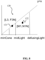
- an x-coordinate value of the first anchor point of the initial pair of anchor points is selected in a range between a predetermined minimum threshold value, and a predetermined center threshold value; and/or an x-coordinate value of the second anchor point of the initial pair of anchor points is selected in a range between the predetermined center threshold value and a predetermined maximum threshold value.
- the predetermined minimum threshold value may be, for example, a brightness value at which human vision cone cells can still perceive color, hereinafter, also referred to as "minCone", and particularly may have a value of 0.15.
- the predetermined center threshold value may be, for example, a minimum human skin color brightness value of the HDR video frame (hereinafter, also referred to as "midLight"), and particularly may have a value of 0.35.
- the predetermined maximum threshold value may be, for example, a brightness value of diffuse white (hereinafter, also referred to as "defusingLight”) as an upper threshold.
- defusingLight a brightness value of diffuse white
- an improved tone mapping curve may be obtained.
- a y-coordinate value of the second anchor point of the initial pair of anchor points is calculated based on a histogram of brightness values of the HDR video frame.
- the histogram of brightness values of the HDR video frame may be a histogram of pixels between the "minCone” and the "maxSource”.
- the method further comprises calculating a number of pixels having brightness values between the predetermined minimum threshold value and the predetermined maximum threshold value; comparing values of histogram bins of the histogram of brightness values with the calculated number of pixels; and if a value of one or more histogram bins is larger than the calculated number, clipping the pixel brightness values in the one or more histogram bins which are larger than a predetermined maximum display brightness value, and setting a y-coordinate value of the second anchor point to be an average value of the brightness values of all pixels belonging to the one or more histogram bins larger than the calculated number; and if no value of one or more histogram bins is larger than the calculated number, clipping the pixel brightness values of pixels between the predetermined center threshold and the predetermined maximum threshold value, and setting the y-coordinate value of the second anchor point to be an average value of the brightness values of all pixels between the predetermined center threshold value of the HDR video frame and the predetermined maximum threshold value.
- the method further comprises generating the tone mapping curve based on the one or more curve parameters.
- the method further comprises receiving the metadata and the HDR video frame.
- the method further transmitting the one or more curve parameters as further metadata.
- the method is performed by an encoder and/or by a decoder.
- a second aspect of the disclosure provides an encoder for encoding HDR video frames, wherein the encoder is configured to perform the method according to the first aspect and/or any of the implementation forms of the first aspect.
- the encoder of the second aspect achieves the advantages and effects described for the method of the first aspect.
- a third aspect of the disclosure provides a decoder for decoding HDR video frames, wherein the decoder is configured to perform the method according to the first aspect and/or any of the implementation forms of the first aspect.
- the decoder of the third aspect achieves the advantages and effects described for the method of the first aspect.
- a fourth aspect of the disclosure provides a system for generating a tone mapping curve, the system comprising an encoder according to the second aspect and/or any of its implementation forms; and a decoder according to the third aspect and/or any of its implementation forms.
- a sixth aspect of the present disclosure provides a non-transitory storage medium storing executable program code which, when executed by a processor, causes the method according to the first aspect and/or any of its implementation forms to be performed.
- FIG. 1 shows a schematic view of a device 100 according to an embodiment of the invention.
- the device 100 may be an encoder for encoding HDR video frames.
- the device 100 may be a decoder for decoding HDR video frames.
- a system may further be formed, comprising at least one such encoder and one such decoder.
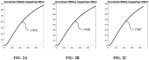
- the device 100 may be configured to perform a method 1100 (see also the schematic diagram shown in FIG. 11 ) for generating one or more curve parameters 131, 132 of a tone mapping curve 130.
- the curve parameters 131 and 132 may be the parameters m_a and m_p, respectively, as discussed above.
- the tone mapping curve 130 can be used to tone-map HDR video frames.
- embodiments of the invention may be implemented in block 1201 or 1204 of a pipeline 1200 as shown in FIG. 12 .
- the method 1100 may be performed in block 1201 or 1204 of the pipeline 1200.
- the device 100 is configured to obtain an HDR video frame 111 and metadata 112 associated to the HDR video frame 111.
- the device 100 may receive the metadata 112 and the HDR video frame 111, e.g., separately.
- the device 100 may, however, also extract the metadata 112 from the HDR video frame 111.
- the metadata 112 may be dynamic metadata, meaning that the metadata 112 may change from one HDR video frame 111 to another HDR video frame 111, and/or from scene to scene of the HDR video.
- the device 100 is further configured to obtain a pair of anchor points 120.
- the pair of anchor points 120 comprises a first anchor point 121 and a second anchor point 122 of the tone mapping curve 130.
- the device 100 may obtain the pair of anchor points 120 based on the obtained HDR video frame 111 and/or the obtained metadata 112.
- the device 100 may also be configured to select the pair of anchor points 120 from a plurality of anchor points 120, for instance, from multiple candidate pairs of anchor points 120. The selection may be based on the pair of anchor points 120 that provides the highest local contrast, if the pair of anchor points 120 is used to approximate the tone mapping curve and a tone mapping operation is performed based on the approximated tone mapping curve.
- the device 100 is configured to generate the one or more curve parameters 131, 132 (e.g., the curve parameters m_a and m_p) of the tone mapping curve 130, based on the pair of anchor points 120.
- the one or more curve parameters 131, 132 may thereby define the tone mapping curve 130
- the device 100 may further generate the tone mapping curve 130 based on the one or more curve parameters 131, 132 (e.g., the curve parameters m_a and m_p). Further, the device 100 may then perform tone mapping on the HDR video frame 111 using the generated tone mapping curve 130.
- the decoder or decoding device may comprise a display or may be connected to a display and may output the tone mapped HDR video frame to the display.
- encoders may also generate the tone mapping curve, e.g. in case the encoder or encoding device comprises a display or is connected to a display and output the tone mapped HDR video frame to the display, but may also just determine the one or more curve parameters of a tone mapping curve (e.g. for transmission or storage) but not generate the tone mapping curve or the respective tone mapped HDR video as such.
- tone mapping curve 130 may be a so-called "phoenix" tone mapping curve described below.
- the device 100 may comprise a processing circuitry (not shown in FIG. 1 ) configured to perform, conduct or initiate the various operations of the device 100 described herein.
- the processing circuitry may comprise hardware and software.
- the hardware may comprise analog circuitry or digital circuitry, or both analog and digital circuitry.
- the digital circuitry may comprise components such as application-specific integrated circuits (ASICs), field-programmable arrays (FPGAs), digital signal processors (DSPs), or multi-purpose processors.
- the processing circuitry comprises one or more processors and a non-transitory memory connected to the one or more processors.
- the non-transitory memory may carry executable program code which, when executed by the one or more processors, causes the device 100 to perform, conduct or initiate the operations or methods described herein.
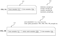
- the basic metadata 312 may comprise a minimum set of parameters that may be sufficient to compute the curve parameters 131 and 132 (e.g., the curve parameters m_a and m_p).
- the basic metadata 312 may include the four parameters as follows (with reference to the CUVA HDR standard):
- These parameters of the basic metadata 312 may be transmitted by the encoder and received by the decoder (e.g. in case both encoder and decoder operate in the automatic mode), and may be used by the decoder as a basis to generate the one or more curve parameters 131, 132, i.e., to first obtain the pair of anchor points 120 based on the basic metadata 312, and then generate the curve parameters 131, 132 based on the pair of anchor points 120 as explained before.
- the metadata 112 may optionally comprise color metadata 322a (e.g. color adjustment or weighting factors).
- the one or more curve parameters 131, 132 e.g., the curve parameters m_a and m_p
- the tone mapping curve 130 e.g., the "phoenix" curve
- the one or more curve parameters 131, 132 can be computed based on the basic metadata 312 of the metadata 112 and, optionally, based on the color metadata 322a.
- the further metadata 322b may, in particular, be referred to as artistic mode metadata 322b (with reference to the CUVA HDR standard).
- the further metadata 322b may also comprise cubic spline parameters such as "TH1, TH2, TH3, TH_strength" in addition to the generated tone mapping curve parameters 131,132 (which are, e.g., the computed "phoenix "curve parameters m_a, m_p).
- TH1 and TH3 are x-values of the starting and ending point of the cubic spline curve. The y-values are the same as the corresponding points on the phoenix curve.
- TH2 is the x-value in between.
- TH_strength is the y-value of the cubic spline curve at TH2, which may control the height of the cubic spline curve.
- a cubic spline curve may be used which may replace the basic tone mapping curve (phoenix curve).
- one or more cubic spline curves in non-overlapping ranges may be supported.
- the decoder may generate the tone mapping curve 130 based on the further metadata 322b.
- the decoder may use the one or more curve parameters 131, 132 (e.g., the curve parameters m_a and m_p) included in the further metadata 322b for generating the tone mapping curve 130.
- the decoder may extract the one or more curve parameters 131, 132 (e.g., the curve parameters m_a and m_p) from the further metadata 322b.
- the decoder could also discard these curve parameters 131, 132 contained in the further metadata 322b, and could calculate new one or more curve parameters 131, 132 based on the basic metadata 312, for instance (e.g. in case the decoder does not support the "artistic mode").
- the difference between the first mode (e.g., automatic mode) and the second mode (e.g., artistic mode) is that in the first mode, the basic metadata 312 (of the metadata 112) is transmitted to the decoder, and the decoder generates the one or more curve parameters 131, 132 based thereon.
- the one or more curve parameters 131, 132 are computed at the encoder, and are embedded in the metadata 112 as the further metadata 322b, and sent to the decoder.
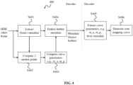
- FIG. 4 shows an embodiment of the invention, wherein the method 1100 is performed at the encoder in the second mode (e.g. artistic mode).
- FIG. 4 shows a flowchart of a method 400 performed by the system of the encoder and a decoder (may be a conventional decoder), wherein the encoder generates the one or more curve parameters 131, 132, and transmits the one or more generated curve parameters 131, 132 as the further metadata 322b to the decoder.
- a decoder may be a conventional decoder
- the method 400 is exemplary discussed for the system, wherein some of the steps (i.e., the steps S401-S404) are performed by the encoder, and some of the steps (i.e., the steps S405-S406) are performed by the decoder, without limiting the present disclosure.
- the encoder may thereby obtain one or more of the following parameters: a maximum display brightness, MaxDisplay(PQ value); a minimum display brightness, MinDisplay(PQ value); an RGB domain pixel buffer f[Nframe][3] of the current HDR video frame 111.
- the f[Nframe][3] may be a 2-d array, wherein Nframe is the number of pixels in the current HDR video frame 111, and 3 represents the 3 color channels, i.e. R, G, B.
- f[11][0] may be the R value of the 12 th pixel in raster scan order, f[11] [1] is G, and f[11][2] is B.
- the encoder obtains the pair of anchor points 120 as described above (a more detailed description of how the pair of anchor points 120 may be obtained/selected is given further below). For example, the encoder may compute two anchor points including the first anchor point 121 and the second anchor point 122 described above. As will be explained below, the encoder may select a pair of anchor points 120, may fine tune the pair of anchor points 120 (e.g., based on tone-mapping producing the highest local contrast).
- the encoder generates the one or more curve parameters 131 and 132 (e.g., the curve parameters m_a and m_p) of the tone mapping curve 130, based on the pair of anchor points 120.
- the encoder may compute the curve parameters m_a and m_p described above for the phoenix curve, based on the pair of anchor points 120.
- the encoder may generate a curve parameter set P tone_mapping , including one or more of the following parameters (parameters as described above): m_p, m_m, m_n, m_b, K1, K2, K3.
- the m_p and m_a may be non-trival, and the other parameters may all be preset (m_m: 2.4; m_n: 1; K1, K2, K3 are all 1).
- the decoder obtains the curve parameters 131, 132.
- the decoder may extract the one or more curve parameters 131, 132 (e.g. the parameters m_a and m_p) from the obtained enhanced metadata 112, particularly from the further metadata 322b.
- FIG. 5 shows another embodiment of the invention, wherein the method 1100 is performed at the decoder in the first mode (e.g. automatic mode).
- FIG. 5 shows a flowchart of a method 500 performed by the system of an encoder (may be a conventional encoder) and the decoder, wherein the decoder generates the one or more curve parameters 131, 132 (e.g., the curve parameters m_a and m_p).
- step S501 is performed by the encoder
- steps S502-S504 are performed by the decoder, without limiting the present disclosure.
- the encoder obtains metadata 112.
- the encoder may obtain an HDR video frame 111 (e.g., from an HDR video source), and may extract the metadata 112, in particular, the basic metadata 312, from the HDR video frame 111.
- the encoder may then provide the metadata 112 and the HDR video frame 111 to the decoder. That is, the decoder may receive the metadata 112 and the HDR video frame 111.
- the decoder obtains a pair of anchor points 120.
- the decoder may obtain the pair of anchor points 120 based on the received HDR video frame 111 and/or the basic metadata 312.
- the pair of anchor points 120 may include the first anchor point 121 and the second anchor point 122.
- the encoder may select a pair of anchor points 120, may fine tune the pair of anchor points 120 (e.g., based on tone-mapping producing the highest local contrast).
- the decoder generates the one or more curve parameters 131 and 132 (e.g., the curve parameters m_a and m_p) of the tone mapping curve 130 based on the pair of anchor points 120.
- the decoder 200 may compute the curve parameters m_a and m_p of the phoenix curve from the pair of anchor points 120.
- the HDR video frame 111 at the decoder is different from the HDR video frame 111 at the encoder, e.g., because of video compression.
- the method 1100 may be performed before encoding, and thus the original HDR video frame 111 may be processed. Performing the method 1100 at the encoder allows to reduce the complexity (performed only once at the encoder and not at each decoder and may also provide better parameters, and thus better quality, because it may use the original HDR video frame for determining the one or more curve parameters).
- the decoder it may be the encoded and compressed HDR video frame 111 that may be decoded and processed by the method 1100.
- FIG. 6 shows a flowchart of an exemplary method 600 for determining the pair of anchor points 120 for generating the one or more curve parameters 131, 132 (e.g., the curve parameters m_a and m_p), as described above.
- the method 600 describes an example of selecting a pair of anchor points 120, and fine tuning the pair of anchor points 120 (e.g., based on tone-mapping producing the highest local contrast), as also described above.
- the pair of anchor points 120 for generating the one or more curve parameters 131, 132 is selected from a plurality of pairs of anchor points 120.
- the method 600 comprises obtaining a plurality of pairs of anchor points 120 (by the device 100), generating a piecewise linear curve 901 for each pair of the plurality of pairs of anchor points 120, performing tone mapping on the HDR video frame 111 based on each of the piecewise linear curves 901 to obtain a plurality of tone-mapped HDR video frames, and selecting the pair of anchor points 120 for generating the one or more curve parameters 131, 132 (e.g., the curve parameters m_a and m_p) from the plurality of pairs of anchor points 120 based on the plurality of tone-mapped HDR video frames.
- the curve parameters 131, 132 e.g., the curve parameters m_a and m_p
- the device 100 may compute the histogram of maxRGB values in the range of (minCone, MaxSource), and a histogram bin size may be set to (MaxSource-minCone)*V/U, wherein U and V are positive integers, U is recommended to be 6, and V is smaller than or equal to 3. Further, the device 100 may compute the number of pixels with maxRGB value in the range of (midLight, defusingLight), and names it Half_Num. Moreover, if the number of samples of a histogram bin is larger than Half_Num, this bin is referred to as a HISA bin.
- the device 100 may calculate a number of pixels having brightness values between the predetermined minimum threshold value and the predetermined maximum threshold value. Further, the device 100 may compare values of histogram bins of the histogram of brightness values with the calculated number of pixels. Then, if a value of one or more histogram bins is larger than the calculated number, clipping the pixel brightness values in the one or more histogram bins which are larger than a predetermined maximum display brightness value, and setting a y-coordinate value of the second anchor point to be an average value of the brightness values of all pixels belonging to the one or more histogram bins larger than the calculated number.
- the device 100 computes one or more further candidates for the first anchor point 121 and the second anchor point 122, i.e. one or more further pairs of anchor points 120.
- the device 100 may obtain the one or more further pairs of anchor points 120 based on the initial pair of anchor points 120.
- the device 100 may obtain further candidates for the second anchor point 122 denoted as (M1, N1N-M1*MaxDisplay*E/(MaxSource*10)), and may obtain further candidates for the first anchor point 121 donated as (L3, F3N*MaxDisplay*F/(MaxSource*10).
- the device 100 may select different values of E and F to obtain more candidate pairs of anchor points 120.
- a value range for E may be between [1, 20], and for F may be between [1, 10].
- a y-coordinate value of the first anchor point 121 of the further pair of anchor points 120 may be different to a y-coordinate value of the initial first anchor point 121, and/or a y-coordinate value of the second anchor point 122 of the further pair of anchor points 120 may be identical to a y-coordinate value of the initial second anchor point 122.
- the device 100 generates a piecewise linear curves 901 for each pair of anchor points 120, i.e. for each of the plurality of pairs of anchor points 120, including the initial pair of anchor points 120 and the one or more further pairs of anchor points 120.
- FIG. 9 shows in this respect a diagram illustrating exemplary a generated piecewise linear curve 901 for a pair of anchor points 120.
- the piecewise linear curve 901 of each pair of anchor points 120 connects a predetermined minimum anchor point 902 with the respective first anchor point 121, the respective first anchor point 121 with the respective second anchor point 122, and the respective second anchor point 122 with a predetermined maximum anchor point 902.
- the device 100 may select a pair of candidate anchor points 121, 122 together with the (minSource, minDisplay), i.e. the minimum anchor point 902, and the (maxSource, maxDisplay), i.e. the maximum anchor point 902, to generate a piecewise linear curve 901 for this pair of anchor points 120.
- This piecewise linear curve 901 may be used as a candidate to approximate the final tone mapping curve 130.
- the device 100 conducts tone-mapping using the piecewise linear curve 901, and compute local contrasts.
- the device 100 may perform tone mapping on the HDR video frame 111 based on each of the piecewise linear curves 901 to obtain a plurality of tone-mapped HDR video frames.
- the device 100 may also determine for each of the plurality of tone-mapped HDR video frames a local contrast to obtain a plurality of local contrasts.
- tone mapping may be conducted for the current HDR video frame 11 using each piecewise linear curve 901, and the local contrast is calculated.
- the local contrast may be computed for the tone-mapped HDR video frame as follows:
- the device 100 may then select the pair of anchor points 120 for generating the one or more curve parameters 131, 132 (e.g., the curve parameters m_a and m_p) from the plurality of pairs of anchor points 120 based on the plurality of tone-mapped HDR video frames, in particular, based on the plurality of local contrasts. For instance, the device 100 may select the pair of anchor points 120 leading to the highest local contrast.
- the curve parameters 131, 132 e.g., the curve parameters m_a and m_p
- the device 100 may select separately the value E and value F that lead to the maximum local contrast for the tone-mapped HDR video frames, and calculate the final anchor points 121 and 122, i.e. [L3, F3], [M1, N1].
- the device 100 may obtain some preset parameters of the tone mapping curve 130.
- the device 100 computes the curve parameters 131, 132, e.g. it may compute the parameters m_p and m_a, for the tone mapping curve 130.
- the device 100 may generate the tone mapping curve 130.
- the device 100 may also send the preset parameters of the tone mapping curve 130 in addition.
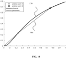
- FIG. 10 shows, for comparison, a tone mapping curve 130 generated based on the one or more generated curve parameters 131, 132, and shows a piecewise linear curve 901 generated based on a selected pair of anchor points 121, from which piecewise linear curve 901 the one or more curve parameters 131, 132 were generated.
- FIG. 11 shows a flowchart of the method 1100 for determining the one or more curve parameters 131, 132, according to an embodiment of the invention.
- the method 1100 may be performed by the device 100, i.e., the encoder or the decoder as described above.
- the method 1100 comprises a step S1101 of obtaining an HDR video frame 111 and metadata 112 associated to the HDR video frame 111.
- the method 1100 further comprises a step S1102 of obtaining a pair of anchor points 120, wherein the pair of anchor points 120 comprises a first anchor point 121 and a second anchor point 122 of the tone mapping curve 130, based on the HDR video frame 111 and the metadata 112.
- the method 1100 further comprises a step S1103 of generating the one or more curve parameters 131, 132 of the tone mapping curve 130 based on the pair of anchor points 120.
- the one or more curve parameters 131, 132 may be, for example, the curve parameters m_a and m_p, respectively.
- FIG. 12 shows an example of a signal processing pipeline 1200 of an HDR dynamic tone mapping process.
- the input of the system is the HDR video, e.g. a HDR video frame of the HDR video.
- this HDR video may be the output of the post-production stage, in which a colorist has edited the video using a color grading system for better quality or for certain artistic intent.
- the HDR video is of high peak brightness, and could be often 1000 nit, or 2000 nit, and in the near future 4000 nit or 10000 nit.
- the pixel values of the video are in the PQ domain.
- the HDR video remains the same as the input. However, metadata is computed. Further, in the HDR video coding block 1202, the HDR video is compressed, e.g. by a video codec, e.g. a video codec according to H.265 or any other video standard (national, international or proprietary). Moreover, the metadata is embedded in the headers of the video stream, which is sent from the encoder to the decoder (or stored on a storage medium for later retrieval by a decoder). In the HDR video decoding block 1203, the decoder receives the HDR video bitstream, decodes the compressed video, and extracts the metadata from the headers.
- a video codec e.g. a video codec according to H.265 or any other video standard (national, international or proprietary).
- the metadata is embedded in the headers of the video stream, which is sent from the encoder to the decoder (or stored on a storage medium for later retrieval by a decoder).
- the decoder receives the
- a tone mapping is conducted, to adapt the HDR video to the display capacity.
Landscapes
- Physics & Mathematics (AREA)
- General Physics & Mathematics (AREA)
- Engineering & Computer Science (AREA)
- Theoretical Computer Science (AREA)
- Image Processing (AREA)
- Compression Or Coding Systems Of Tv Signals (AREA)
- Studio Devices (AREA)
- Picture Signal Circuits (AREA)
Applications Claiming Priority (1)
| Application Number | Priority Date | Filing Date | Title |
|---|---|---|---|
| PCT/CN2020/089134 WO2021223205A1 (en) | 2020-05-08 | 2020-05-08 | Encoder, decoder, system, and method for determining tone mapping curve parameters |
Publications (3)
| Publication Number | Publication Date |
|---|---|
| EP4028987A1 EP4028987A1 (en) | 2022-07-20 |
| EP4028987A4 EP4028987A4 (en) | 2022-10-12 |
| EP4028987B1 true EP4028987B1 (en) | 2025-07-09 |
Family
ID=78467683
Family Applications (1)
| Application Number | Title | Priority Date | Filing Date |
|---|---|---|---|
| EP20934496.9A Active EP4028987B1 (en) | 2020-05-08 | 2020-05-08 | Encoder, decoder, system, and method for determining tone mapping curve parameters |
Country Status (7)
| Country | Link |
|---|---|
| US (1) | US12444033B2 (pl) |
| EP (1) | EP4028987B1 (pl) |
| JP (2) | JP7476354B2 (pl) |
| KR (1) | KR102727392B1 (pl) |
| CN (1) | CN115428006A (pl) |
| PL (1) | PL4028987T3 (pl) |
| WO (1) | WO2021223205A1 (pl) |
Families Citing this family (7)
| Publication number | Priority date | Publication date | Assignee | Title |
|---|---|---|---|---|
| JP2020036790A (ja) * | 2018-09-05 | 2020-03-12 | 株式会社三洋物産 | 遊技機 |
| JP2020036791A (ja) * | 2018-09-05 | 2020-03-12 | 株式会社三洋物産 | 遊技機 |
| JP2020036793A (ja) * | 2018-09-05 | 2020-03-12 | 株式会社三洋物産 | 遊技機 |
| KR102727392B1 (ko) * | 2020-05-08 | 2024-11-06 | 후아웨이 테크놀러지 컴퍼니 리미티드 | 톤 매핑 곡선 파라미터를 결정하기 위한 인코더, 디코더, 시스템, 및 방법 |
| CN116681598A (zh) * | 2022-02-23 | 2023-09-01 | 深圳市汇顶科技股份有限公司 | 图像处理方法、芯片、电子设备和计算机可读存储介质 |
| US20240029219A1 (en) * | 2022-07-25 | 2024-01-25 | Nbcuniversal Media, Llc | Dynamic tone-mapping system normalized around reference white |
| CN118488157B (zh) * | 2023-10-23 | 2025-09-05 | 镕铭微电子(上海)有限公司 | 图像处理方法、装置、电子设备及存储介质 |
Family Cites Families (33)
| Publication number | Priority date | Publication date | Assignee | Title |
|---|---|---|---|---|
| JP4720537B2 (ja) * | 2006-02-27 | 2011-07-13 | コニカミノルタホールディングス株式会社 | 撮像装置 |
| JP4860551B2 (ja) * | 2007-06-01 | 2012-01-25 | 株式会社キーエンス | 拡大観察装置、高階調画像ファイル作成方法、高階調画像ファイル作成方法、高階調画像ファイル作成プログラム及びコンピュータで読み取り可能な記録媒体 |
| WO2011002505A1 (en) * | 2009-06-29 | 2011-01-06 | Thomson Licensing | Zone-based tone mapping |
| KR101787788B1 (ko) * | 2010-02-19 | 2017-10-18 | 톰슨 라이센싱 | 높은 동적 범위 비디오 톤 맵핑을 위한 파라미터 보간 |
| US8314847B2 (en) * | 2010-05-25 | 2012-11-20 | Apple Inc. | Automatic tone mapping curve generation based on dynamically stretched image histogram distribution |
| KR101843902B1 (ko) * | 2010-06-25 | 2018-04-02 | 톰슨 라이센싱 | 높은 동적 범위 비디오를 톤 맵핑하기 위한 그래픽 사용자 인터페이스 |
| TWI538474B (zh) * | 2011-03-15 | 2016-06-11 | 杜比實驗室特許公司 | 影像資料轉換的方法與設備 |
| EP2959682B1 (en) * | 2013-02-21 | 2018-12-05 | Dolby Laboratories Licensing Corporation | Display management for high dynamic range video |
| WO2015007505A1 (en) * | 2013-07-18 | 2015-01-22 | Koninklijke Philips N.V. | Methods and apparatuses for creating code mapping functions for encoding an hdr image, and methods and apparatuses for use of such encoded images |
| US10362337B2 (en) * | 2014-08-08 | 2019-07-23 | Koninklijke Philips N.V. | Methods and apparatuses for encoding HDR images |
| RU2659485C1 (ru) * | 2015-01-19 | 2018-07-02 | Долби Лабораторис Лайсэнзин Корпорейшн | Управление отображением видеоизображения с расширенным динамическим диапазоном |
| CN107258078B (zh) * | 2015-01-30 | 2019-09-24 | 皇家飞利浦有限公司 | 简单但通用的动态范围编码 |
| CA2997118A1 (en) * | 2015-09-02 | 2017-03-09 | Irystec Software Inc. | System and method for real-time tone-mapping |
| US9979895B2 (en) * | 2015-09-04 | 2018-05-22 | Disney Enterprises, Inc. | High dynamic range tone mapping |
| US9984446B2 (en) * | 2015-12-26 | 2018-05-29 | Intel Corporation | Video tone mapping for converting high dynamic range (HDR) content to standard dynamic range (SDR) content |
| EP3220349A1 (en) * | 2016-03-16 | 2017-09-20 | Thomson Licensing | Methods, apparatus, and systems for extended high dynamic range ("hdr") hdr to hdr tone mapping |
| MX386571B (es) * | 2016-03-18 | 2025-03-19 | Koninklijke Philips Nv | Codificación y decodificación de videos de alto intervalo dinámico (hdr). |
| US10219345B2 (en) * | 2016-11-10 | 2019-02-26 | Ledengin, Inc. | Tunable LED emitter with continuous spectrum |
| WO2018111682A1 (en) * | 2016-12-12 | 2018-06-21 | Dolby Laboratories Licensing Corporation | Systems and methods for adjusting video processing curves for high dynamic range images |
| US10176561B2 (en) * | 2017-01-27 | 2019-01-08 | Microsoft Technology Licensing, Llc | Content-adaptive adjustments to tone mapping operations for high dynamic range content |
| PL3559901T3 (pl) * | 2017-02-15 | 2020-11-16 | Dolby Laboratories Licensing Corporation | Odwzorowywanie krzywej tonalnej dla obrazów o wysokim zakresie dynamiki |
| WO2018152063A1 (en) * | 2017-02-15 | 2018-08-23 | Dolby Laboratories Licensing Corporation | Tone curve mapping for high dynamic range images |
| WO2018235337A1 (ja) * | 2017-06-21 | 2018-12-27 | パナソニックIpマネジメント株式会社 | 映像表示システム及び映像表示方法 |
| US10755392B2 (en) * | 2017-07-13 | 2020-08-25 | Mediatek Inc. | High-dynamic-range video tone mapping |
| JP7084984B2 (ja) * | 2017-09-06 | 2022-06-15 | ドルビー ラボラトリーズ ライセンシング コーポレイション | トーンカーブ最適化方法および関連するビデオエンコーダとビデオデコーダ |
| IL276062B2 (en) * | 2018-02-14 | 2023-09-01 | Dolby Laboratories Licensing Corp | Image reshaping in video encoding using rate warping optimization |
| US20210224963A1 (en) * | 2018-04-27 | 2021-07-22 | Sony Corporation | Information processing apparatus, information processing method, image processing apparatus, image processing method, and program |
| CN108900823B (zh) * | 2018-07-05 | 2019-07-12 | 华为技术有限公司 | 一种视频信号处理的方法及装置 |
| EP3853809B1 (en) * | 2018-09-17 | 2025-04-09 | Dolby Laboratories Licensing Corporation | Display mapping for high dynamic range images on power-limiting displays |
| EP3764346A1 (en) * | 2019-07-09 | 2021-01-13 | Koninklijke Philips N.V. | Adjustment of display optimization behaviour for hdr images |
| CN113596424B (zh) * | 2020-04-30 | 2022-12-06 | 华为技术有限公司 | 动态范围映射的方法和装置 |
| KR102727392B1 (ko) | 2020-05-08 | 2024-11-06 | 후아웨이 테크놀러지 컴퍼니 리미티드 | 톤 매핑 곡선 파라미터를 결정하기 위한 인코더, 디코더, 시스템, 및 방법 |
| CN115619648A (zh) * | 2021-07-14 | 2023-01-17 | 华为技术有限公司 | 全景图像的色调映射方法和装置 |
-
2020
- 2020-05-08 KR KR1020227039733A patent/KR102727392B1/ko active Active
- 2020-05-08 PL PL20934496.9T patent/PL4028987T3/pl unknown
- 2020-05-08 JP JP2022567670A patent/JP7476354B2/ja active Active
- 2020-05-08 CN CN202080099463.1A patent/CN115428006A/zh active Pending
- 2020-05-08 EP EP20934496.9A patent/EP4028987B1/en active Active
- 2020-05-08 WO PCT/CN2020/089134 patent/WO2021223205A1/en not_active Ceased
-
2022
- 2022-11-07 US US17/982,221 patent/US12444033B2/en active Active
-
2024
- 2024-04-16 JP JP2024065991A patent/JP7741236B2/ja active Active
Also Published As
| Publication number | Publication date |
|---|---|
| KR20230002720A (ko) | 2023-01-05 |
| CN115428006A (zh) | 2022-12-02 |
| WO2021223205A1 (en) | 2021-11-11 |
| EP4028987A1 (en) | 2022-07-20 |
| JP2024086904A (ja) | 2024-06-28 |
| KR102727392B1 (ko) | 2024-11-06 |
| JP7741236B2 (ja) | 2025-09-17 |
| JP7476354B2 (ja) | 2024-04-30 |
| US20230057829A1 (en) | 2023-02-23 |
| US12444033B2 (en) | 2025-10-14 |
| JP2023525284A (ja) | 2023-06-15 |
| PL4028987T3 (pl) | 2025-10-20 |
| EP4028987A4 (en) | 2022-10-12 |
Similar Documents
| Publication | Publication Date | Title |
|---|---|---|
| EP4028987B1 (en) | Encoder, decoder, system, and method for determining tone mapping curve parameters | |
| US11310537B2 (en) | Linear encoder for image/video processing | |
| RU2666234C1 (ru) | Аппроксимация восстановления формы сигнала | |
| CN106095353B (zh) | 改进不同显示能力之间基于感知照度非线性的图像数据交换的装置和方法 | |
| CN100366052C (zh) | 图像处理设备和方法 | |
| WO2018231968A1 (en) | Efficient end-to-end single layer inverse display management coding | |
| JP2021524647A (ja) | 適応的なsdrからhdrへの再構成関数による、hdr画像化におけるバンディングアーチファクトの低減 | |
| EP3639238A1 (en) | Efficient end-to-end single layer inverse display management coding | |
| CN114467298B (zh) | 一种图像信号转换处理方法、装置及终端设备 | |
| US12177459B2 (en) | Rate-control-aware reshaping in HDR imaging | |
| US20230054477A1 (en) | Determination of a parameter set for a tone mapping curve | |
| US12439096B2 (en) | Context-based reshaping algorithms for encoding video data | |
| CN110999300B (zh) | 用于图像/视频处理的单通道逆映射 | |
| EP4441697A1 (en) | Denoising for sdr-to-hdr local reshaping | |
| HK1199955B (en) | Device and method of improving the perceptual luminance nonlinearity-based image data |
Legal Events
| Date | Code | Title | Description |
|---|---|---|---|
| STAA | Information on the status of an ep patent application or granted ep patent |
Free format text: STATUS: THE INTERNATIONAL PUBLICATION HAS BEEN MADE |
|
| PUAI | Public reference made under article 153(3) epc to a published international application that has entered the european phase |
Free format text: ORIGINAL CODE: 0009012 |
|
| STAA | Information on the status of an ep patent application or granted ep patent |
Free format text: STATUS: REQUEST FOR EXAMINATION WAS MADE |
|
| 17P | Request for examination filed |
Effective date: 20220414 |
|
| AK | Designated contracting states |
Kind code of ref document: A1 Designated state(s): AL AT BE BG CH CY CZ DE DK EE ES FI FR GB GR HR HU IE IS IT LI LT LU LV MC MK MT NL NO PL PT RO RS SE SI SK SM TR |
|
| A4 | Supplementary search report drawn up and despatched |
Effective date: 20220908 |
|
| RIC1 | Information provided on ipc code assigned before grant |
Ipc: G06T 5/00 20060101AFI20220902BHEP |
|
| DAV | Request for validation of the european patent (deleted) | ||
| DAX | Request for extension of the european patent (deleted) | ||
| REG | Reference to a national code |
Ref country code: DE Ref legal event code: R079 Free format text: PREVIOUS MAIN CLASS: G06T0005000000 Ipc: G06T0005920000 Ref country code: DE Ref legal event code: R079 Ref document number: 602020054412 Country of ref document: DE Free format text: PREVIOUS MAIN CLASS: G06T0005000000 Ipc: G06T0005920000 |
|
| GRAP | Despatch of communication of intention to grant a patent |
Free format text: ORIGINAL CODE: EPIDOSNIGR1 |
|
| STAA | Information on the status of an ep patent application or granted ep patent |
Free format text: STATUS: GRANT OF PATENT IS INTENDED |
|
| RIC1 | Information provided on ipc code assigned before grant |
Ipc: G06T 5/92 20240101AFI20250203BHEP |
|
| INTG | Intention to grant announced |
Effective date: 20250214 |
|
| P01 | Opt-out of the competence of the unified patent court (upc) registered |
Free format text: CASE NUMBER: APP_10193/2025 Effective date: 20250227 |
|
| GRAS | Grant fee paid |
Free format text: ORIGINAL CODE: EPIDOSNIGR3 |
|
| GRAA | (expected) grant |
Free format text: ORIGINAL CODE: 0009210 |
|
| STAA | Information on the status of an ep patent application or granted ep patent |
Free format text: STATUS: THE PATENT HAS BEEN GRANTED |
|
| AK | Designated contracting states |
Kind code of ref document: B1 Designated state(s): AL AT BE BG CH CY CZ DE DK EE ES FI FR GB GR HR HU IE IS IT LI LT LU LV MC MK MT NL NO PL PT RO RS SE SI SK SM TR |
|
| REG | Reference to a national code |
Ref country code: GB Ref legal event code: FG4D |
|
| REG | Reference to a national code |
Ref country code: CH Ref legal event code: EP |
|
| REG | Reference to a national code |
Ref country code: IE Ref legal event code: FG4D |
|
| REG | Reference to a national code |
Ref country code: DE Ref legal event code: R096 Ref document number: 602020054412 Country of ref document: DE |
|
| REG | Reference to a national code |
Ref country code: NL Ref legal event code: MP Effective date: 20250709 |
|
| PG25 | Lapsed in a contracting state [announced via postgrant information from national office to epo] |
Ref country code: PT Free format text: LAPSE BECAUSE OF FAILURE TO SUBMIT A TRANSLATION OF THE DESCRIPTION OR TO PAY THE FEE WITHIN THE PRESCRIBED TIME-LIMIT Effective date: 20251110 |
|
| PG25 | Lapsed in a contracting state [announced via postgrant information from national office to epo] |
Ref country code: NL Free format text: LAPSE BECAUSE OF FAILURE TO SUBMIT A TRANSLATION OF THE DESCRIPTION OR TO PAY THE FEE WITHIN THE PRESCRIBED TIME-LIMIT Effective date: 20250709 |
|
| REG | Reference to a national code |
Ref country code: AT Ref legal event code: MK05 Ref document number: 1812578 Country of ref document: AT Kind code of ref document: T Effective date: 20250709 |