EP4028711B1 - Pistol mounted flashlight assembly - Google Patents
Pistol mounted flashlight assembly Download PDFInfo
- Publication number
- EP4028711B1 EP4028711B1 EP20864216.5A EP20864216A EP4028711B1 EP 4028711 B1 EP4028711 B1 EP 4028711B1 EP 20864216 A EP20864216 A EP 20864216A EP 4028711 B1 EP4028711 B1 EP 4028711B1
- Authority
- EP
- European Patent Office
- Prior art keywords
- latch
- assembly
- housing
- flashlight
- received
- Prior art date
- Legal status (The legal status is an assumption and is not a legal conclusion. Google has not performed a legal analysis and makes no representation as to the accuracy of the status listed.)
- Active
Links
Images



Classifications
-
- F—MECHANICAL ENGINEERING; LIGHTING; HEATING; WEAPONS; BLASTING
- F41—WEAPONS
- F41G—WEAPON SIGHTS; AIMING
- F41G1/00—Sighting devices
- F41G1/32—Night sights, e.g. luminescent
- F41G1/34—Night sights, e.g. luminescent combined with light source, e.g. spot light
- F41G1/35—Night sights, e.g. luminescent combined with light source, e.g. spot light for illuminating the target, e.g. flash lights
-
- F—MECHANICAL ENGINEERING; LIGHTING; HEATING; WEAPONS; BLASTING
- F41—WEAPONS
- F41C—SMALLARMS, e.g. PISTOLS, RIFLES; ACCESSORIES THEREFOR
- F41C27/00—Accessories; Details or attachments not otherwise provided for
-
- F—MECHANICAL ENGINEERING; LIGHTING; HEATING; WEAPONS; BLASTING
- F41—WEAPONS
- F41G—WEAPON SIGHTS; AIMING
- F41G11/00—Details of sighting or aiming apparatus; Accessories
- F41G11/001—Means for mounting tubular or beam shaped sighting or aiming devices on firearms
- F41G11/003—Mountings with a dove tail element, e.g. "Picatinny rail systems"
Definitions
- the present invention generally relates to a multi-function pistol mounted flashlight and more specifically to a pistol mounted flashlight having an integrated dovetail rail mounting interface and an improved metal housing construction.
- Flashlights of the type contemplated herein are used by law enforcement and military personnel in rugged outdoor conditions which require a high degree of reliability in all weather conditions. There is a continuing need for improved flashlight assemblies that provide better reliability for mounting and operation, better waterproofing and easier battery changes. US9810411 constitutes relevant prior art.
- the flashlight assembly generally includes an elongated housing, a light assembly received within the front of the housing, a battery door assembly at the rear of the housing, a latch assembly on the top of the housing and a clamp assembly also on the top of the housing. Paddle switches for operating the flashlight are integrated into the battery door assembly at the rear of the housing.
- the battery door assembly is both slidable and rotatable relative to the main housing.
- the invention is defined by a flashlight assembly for use with a pistol, according to the appended claim 1.
- linear or circular dimensions are used in the description of the disclosed systems, devices, and methods, such dimensions are not intended to limit the types of shapes that can be used in conjunction with such systems, devices, and methods. A person skilled in the art will recognize that an equivalent to such linear and circular dimensions can easily be determined for any geometric shape. Further, to the extent that directional terms like top, bottom, up, or down are used, they are not intended to limit the systems, devices, and methods disclosed herein. A person skilled in the art will recognize that these terms are merely relative to the system and device being discussed and are not universal.
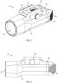
- the flashlight assembly 10 generally includes an elongated housing 12, a light assembly 14 received within the front of the housing 12, a battery door assembly 16 at the rear of the housing 12, a latch assembly 18 on the top of the housing 12 and a clamp assembly 20 also on the top of the housing 12.
- Paddle switches 22, 24 for operating the flashlight are integrated into the battery door assembly 16 at the rear of the housing.
- all components of the present flashlight are preferably fashioned from metal for a durable and rugged construction.
- the all-metal housing 12, clamp 20, battery door 16 and switching paddles 22, 24 provide for an improved and more reliable construction.
- the latch assembly 18 may also be constructed from metal components, but in the exemplary embodiment, these components are molded from a polymer material.
- the housing 12 generally has an opening 26 at the front for receiving the light assembly 14, a recess 28 in the top for receiving the latching assembly 18 and a dual battery compartment opening 30 to the rear. Two side-by-side batteries 32, 34 are received into the compartment 30 for power.
- the clamping assembly 20 includes a fixed clamping arm 48 which is part of the housing 12, a second movable clamping bar 50 and a thumb screw 52 for tightening the movable clamping bar 50.
- the dovetail clamping assembly 20 allows the flashlight assembly 10 to be mounted onto an integrated dovetail rail which runs along a pistol frame forward of the trigger guard. When mounted, the paddle switches 22, 24 straddle the forward end of the trigger guard and are ergonomically positioned for ambidextrous actuation with the user's trigger finger.
- a removable and reversible cross bar 54 extends across the top of the housing 12 and is received in positioning slots in the pistol dovetail rail to prevent sliding of the flashlight assembly 10 when mounted.
- the crossbar configuration includes reversible mil-spec and Weaver dimensions and is further described in US Patent No. 10,352,657 , the entire contents of which are incorporated herein by reference.
- the reversible crossbar 54 is integrated as part of the latch assembly 18 which is inserted and retained within the recess 28 in the top of the housing.
- the latch assembly 18 comprises a housing body 56 with an undercut groove 58 extending laterally across the top and a latch button opening 60 rearward of the crossbar groove 58.
- the crossbar 54 is slidably received within the undercut groove 58.
- a latch button 62 is slidably received in a recess on the underside of the body 56 and extends upwardly through the latch opening 60.
- a spring 64 or plurality of springs, are captured between the bottom of the latch button 62 and the housing 12 and bias position of the latch button 62 upward against the latch body 56 when assembled with the housing 12.
- the latch body 56, latch button 62 and springs 64 are received into the recess 28 in the top of the housing 12 and the latch body 60 is retained in place with two retaining screws 66 at the rear and a single retaining screw 66 at the front.
- two retaining screws 66 at the rear and a single retaining screw 66 at the front.
- the retaining screws 66 are inserted through corresponding openings 68 in the front and rear of the housing 12 during assembly and into threaded apertures 70 in the latch body.
- the bottom of the latch button 62 further includes a latch shoulder 112 (See Fig. 6A ) which engages with a latch pin 78 on the battery door assembly 16.
- the battery door assembly 16 comprises a body portion 72 having a forward side and a rearward side.
- An O-ring gasket 74 is received around the outer periphery of a cavity wall 76 extending forwardly.
- the cavity wall 76 is received in engagement into the battery compartment opening 30 with the gasket 74 providing a waterproof seal.
- a latch pin 78 is received into the top portion of forward side of the battery door body 72.
- the latch pin 78 has a threaded tail end 80 which is threaded into the body 72, a latch head 82 and groove 84 at the front end and a raised shoulder 86 adjacent and rearward of the groove 84.
- the tail end 80 of the latch pin 78 is inserted through a guide hole 88 in the housing 12 from within the top recess 28 and threaded into a threaded bore 90 in the battery door body 72.
- the latch pin shaft allows the latch pin 78 (and entire battery door assembly 16) to slide inwardly and outwardly, however, the raised shoulder 86 engages with the housing 12 to retain the battery door assembly 16 with the housing 12.
- the latch pin 78 also allows the battery door assembly 16 to rotate about the latch 78 when it is not received within the battery opening in the rear of the housing 12. Movement of the battery door assembly 16 will be described further hereinbelow.
- an elastomeric boot 96 Within the forward side cavity of the door body 72 is received an elastomeric boot 96, a circuit board 98 carrying two spaced switches 100, 102, spaced battery contacts 104, 106, an insulating spacer 108 and a signal plate 110.
- the elastomeric boot 96 seals openings in the door body 72 provided for the paddle actuators 22, 24 to contact the switches 100, 102.
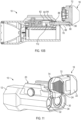
- FIG. 9 depicts a cross-section of the flashlight assembly 10 fully assembled with batteries 32, 34 inserted and the battery door 16 fully latched closed. It can be seen in the upper middle portion of the illustration that the latch pin head 82 and groove 84 engage with a latch shoulder 112 on the underside of the latch button 62.
- the latch button 62 is configured and arranged such that when assembled, the latch pin 78 extends longitudinally through the bottom of the latch button 62 with the latch shoulder 112 extending transversely across the guide hole 88.
- the angled side surfaces of the conical latch pin head 82 engage the latch shoulder 112 and move the latch button 62 downward against the spring bias.
- the spring biased latch shoulder 112 snaps up into the groove 84 and the rearward edge of the head 82 engages the shoulder 112 to prevent rearward movement (latched position).
- the battery door assembly 16 is locked in position.
- the operator may press downwardly on the latch button 62 to release the latch shoulder 112 from the latch pin head 82 (actuated and unlatched) and the battery door assembly 16 may then be pulled rearwardly ( Fig. 10A ).
- the raised shoulder 86 on the latch pin shaft prevents the door assembly 16 from being completely removed from the housing 12.
- the door assembly 16 is rotated 180 degrees ( Fig. 10B and see also Fig. 11 ).
- FIG. 12 the electronic components of the flashlight 10 are illustrated without the various housing components.
- One battery 32 is hidden for better illustration. Electrical contact at the rear is made with the battery contacts 104, 106 mounted on the rear circuit board 98. Electrical contact at the front is made with contact pads (not shown) on the rear surface of the control circuit board 46. The creates a complete internal circuit without any power flowing through the housing 12. Control signals from the two switches 100, 102 on the rear circuit board 98 are routed to the control circuit board 46 at the front through a spring-loaded signal pin 114 extending longitudinally through the housing 12 between the batteries 32, 34.
- the front end of the signal pin 114 makes spring contact with a pad on the rear of the front circuit board 46, while the rear end makes spring contact with the signal plate 110 on the battery door.
- the signal plate 110 is electrically connected to the rear circuit board 98 with a conductive spring 116 that extends through the insulating spacer 108 (see Fig. 8 ).
- different operating modes can be controlled by actuation of either one of the switches 100, 102, or combined actuation of both switches which cause control signals of varying degree to be carried forward to the control circuit board 46.
- the switches 100. 102 may be provided with different resistors (i.e. 10 ohm and 20 ohm) where each signal value triggers a different function, i.e. high power, low power, strobe, etc, and wherein actuation of both switches (for a combined resistor signal) is required to turn the flashlight on or off.
- This combined actuation creates a novel lockout mode which prevents inadvertently turning the flashlight on by pressing only one of the switch paddles 22, 24.
- the exemplary embodiments described herein provide a multi-functional flashlight construction that is easier to operate and maintain, and that exhibits a high degree of functional reliability even in the most rugged environment.
- the instant invention is believed to represent a significant advancement in the art, which has substantial commercial merit.
Landscapes
- Engineering & Computer Science (AREA)
- General Engineering & Computer Science (AREA)
- Physics & Mathematics (AREA)
- Optics & Photonics (AREA)
- Battery Mounting, Suspending (AREA)
Description
- The present invention generally relates to a multi-function pistol mounted flashlight and more specifically to a pistol mounted flashlight having an integrated dovetail rail mounting interface and an improved metal housing construction.
- Flashlights of the type contemplated herein are used by law enforcement and military personnel in rugged outdoor conditions which require a high degree of reliability in all weather conditions. There is a continuing need for improved flashlight assemblies that provide better reliability for mounting and operation, better waterproofing and easier battery changes.
US9810411 - The flashlight assembly generally includes an elongated housing, a light assembly received within the front of the housing, a battery door assembly at the rear of the housing, a latch assembly on the top of the housing and a clamp assembly also on the top of the housing. Paddle switches for operating the flashlight are integrated into the battery door assembly at the rear of the housing. The battery door assembly is both slidable and rotatable relative to the main housing. The invention is defined by a flashlight assembly for use with a pistol, according to the appended claim 1.
- Exemplary embodiments will now be described further by way of example with reference to the following examples and figures, which are intended to be illustrative only and in no way limiting upon the scope of the disclosure.
-
Fig. 1 is a perspective view of an exemplary flashlight assembly in accordance with the present invention; -
Fig. 2 is a side view thereof; -
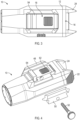
Fig. 3 is a top view thereof; -
Fig. 4 is a partially exploded perspective view with the clamping bar moved to reveal the crossbar and latch assembly; -
Fig. 5 is an exploded perspective view of the flashlight assembly; -
Fig. 6 is another exploded perspective view thereof; -
Fig. 6A is a bottom perspective view of the latch assembly; -
Fig. 7 is an exploded perspective of the crossbar and latch assembly; -
Fig. 8 is an exploded view of the battery door assembly; -
Fig. 9 is a cross-sectional view of the flashlight assembly taken along line 9-9 ofFig. 3 ; -
Figs. 10A and10B are further cross-sectional view thereof showing sequential unlatching and outward sliding of the battery door (Fig. 9A) and rotation thereof (Fig. 9B) to provide access to the battery compartment and batteries; -
Fig. 11 is a perspective view of the flashlight assembly with the battery door assembly unlatched and rotated upwardly to expose the battery compartment; and -
Fig. 12 is a perspective view of the internal electronic component assembly. - Certain exemplary embodiments will now be described to provide an overall understanding of the principles of the structure, function, manufacture, and use of the device and methods disclosed herein. One or more examples of these embodiments are illustrated in the accompanying drawings. Those skilled in the art will understand that the devices and methods specifically described herein and illustrated in the accompanying drawings are non-limiting exemplary embodiments and that the scope of the present invention is defined solely by the claims. The features illustrated or described in connection with one exemplary embodiment may be combined with the features of other embodiments. Such modifications and variations are intended to be included within the scope of the present disclosure. Further, in the present disclosure, like-numbered components of the embodiments generally have similar features, and thus within a particular embodiment each feature of each like-numbered component is not necessarily fully elaborated upon. Additionally, to the extent that linear or circular dimensions are used in the description of the disclosed systems, devices, and methods, such dimensions are not intended to limit the types of shapes that can be used in conjunction with such systems, devices, and methods. A person skilled in the art will recognize that an equivalent to such linear and circular dimensions can easily be determined for any geometric shape. Further, to the extent that directional terms like top, bottom, up, or down are used, they are not intended to limit the systems, devices, and methods disclosed herein. A person skilled in the art will recognize that these terms are merely relative to the system and device being discussed and are not universal.
- Now referring to the drawings, an exemplary embodiment of the present flashlight assembly is shown and generally indicated at 10 in
Figures 1-12 . Theflashlight assembly 10 generally includes anelongated housing 12, alight assembly 14 received within the front of thehousing 12, abattery door assembly 16 at the rear of thehousing 12, alatch assembly 18 on the top of thehousing 12 and aclamp assembly 20 also on the top of thehousing 12. Paddle switches 22, 24 for operating the flashlight are integrated into thebattery door assembly 16 at the rear of the housing. - With the exception of the
latch assembly 18, all components of the present flashlight are preferably fashioned from metal for a durable and rugged construction. The all-metal housing 12,clamp 20,battery door 16 and switchingpaddles latch assembly 18 may also be constructed from metal components, but in the exemplary embodiment, these components are molded from a polymer material. - The
housing 12 generally has anopening 26 at the front for receiving thelight assembly 14, arecess 28 in the top for receiving thelatching assembly 18 and a dual battery compartment opening 30 to the rear. Two side-by-side batteries compartment 30 for power. - The
light assembly 14 comprises a heat sink/reflector body 36 to collect and dissipate the waste heat generated during operation of the flashlight as well as reflect light from anLED 38. Thereflector body 36 is inserted into the opening 26 in the front of thehousing 12. Aretaining ring 40 retains alens 42 spanning across the opening 26. Adjacent a rear surface of thereflector body 36 is acircuit board 44 that includes the at least oneLED 38 positioned thereon. In the exemplary embodiment, theLED 38 is a single visible white LED positioned centrally within thereflector body 36. Optionally, there may be one or more other LEDs (not shown) positioned adjacent the white LED. The LED(s) is/are controlled by a processor and other circuitry on a separatecontrol circuit board 46 positioned rearwardly of theLED circuit board 44. - The
clamping assembly 20 includes a fixedclamping arm 48 which is part of thehousing 12, a secondmovable clamping bar 50 and athumb screw 52 for tightening themovable clamping bar 50. Thedovetail clamping assembly 20 allows theflashlight assembly 10 to be mounted onto an integrated dovetail rail which runs along a pistol frame forward of the trigger guard. When mounted, the paddle switches 22, 24 straddle the forward end of the trigger guard and are ergonomically positioned for ambidextrous actuation with the user's trigger finger. - Turning to
Fig. 4-7 , a removable andreversible cross bar 54 extends across the top of thehousing 12 and is received in positioning slots in the pistol dovetail rail to prevent sliding of theflashlight assembly 10 when mounted. The crossbar configuration includes reversible mil-spec and Weaver dimensions and is further described inUS Patent No. 10,352,657 reversible crossbar 54 is integrated as part of thelatch assembly 18 which is inserted and retained within therecess 28 in the top of the housing. Thelatch assembly 18 comprises ahousing body 56 with anundercut groove 58 extending laterally across the top and a latch button opening 60 rearward of thecrossbar groove 58. Thecrossbar 54 is slidably received within theundercut groove 58. - A
latch button 62 is slidably received in a recess on the underside of thebody 56 and extends upwardly through the latch opening 60. Aspring 64, or plurality of springs, are captured between the bottom of thelatch button 62 and thehousing 12 and bias position of thelatch button 62 upward against thelatch body 56 when assembled with thehousing 12. In this regard, thelatch body 56,latch button 62 and springs 64 are received into therecess 28 in the top of thehousing 12 and thelatch body 60 is retained in place with two retainingscrews 66 at the rear and a single retainingscrew 66 at the front. As best seen inFigs. 5 ,6 and6A , the retaining screws 66 are inserted throughcorresponding openings 68 in the front and rear of thehousing 12 during assembly and into threadedapertures 70 in the latch body. As will be described further herein, the bottom of thelatch button 62 further includes a latch shoulder 112 (SeeFig. 6A ) which engages with alatch pin 78 on thebattery door assembly 16. - Moving to
Fig. 8 , thebattery door assembly 16 comprises abody portion 72 having a forward side and a rearward side. An O-ring gasket 74 is received around the outer periphery of acavity wall 76 extending forwardly. When thebattery door assembly 16 is assembled with thehousing 12, thecavity wall 76 is received in engagement into the battery compartment opening 30 with thegasket 74 providing a waterproof seal. - A
latch pin 78 is received into the top portion of forward side of thebattery door body 72. Thelatch pin 78 has a threadedtail end 80 which is threaded into thebody 72, alatch head 82 andgroove 84 at the front end and a raisedshoulder 86 adjacent and rearward of thegroove 84. During assembly, thetail end 80 of thelatch pin 78 is inserted through aguide hole 88 in thehousing 12 from within thetop recess 28 and threaded into a threadedbore 90 in thebattery door body 72. The latch pin shaft allows the latch pin 78 (and entire battery door assembly 16) to slide inwardly and outwardly, however, the raisedshoulder 86 engages with thehousing 12 to retain thebattery door assembly 16 with thehousing 12. Thelatch pin 78 also allows thebattery door assembly 16 to rotate about thelatch 78 when it is not received within the battery opening in the rear of thehousing 12. Movement of thebattery door assembly 16 will be described further hereinbelow. - On the rearward side of the
door assembly 16 are received the opposing L-shapedpaddle actuators paddle actuators US Patent No. 9,810,411 - Within the forward side cavity of the
door body 72 is received anelastomeric boot 96, acircuit board 98 carrying two spacedswitches battery contacts spacer 108 and asignal plate 110. Theelastomeric boot 96 seals openings in thedoor body 72 provided for thepaddle actuators switches - Cross-sectional
figures 9 and 10A , 10B illustrate the various positions of thebattery door assembly 16,latch pin 78, andlatch button 62.Fig. 9 depicts a cross-section of theflashlight assembly 10 fully assembled withbatteries battery door 16 fully latched closed. It can be seen in the upper middle portion of the illustration that thelatch pin head 82 andgroove 84 engage with alatch shoulder 112 on the underside of thelatch button 62. Thelatch button 62 is configured and arranged such that when assembled, thelatch pin 78 extends longitudinally through the bottom of thelatch button 62 with thelatch shoulder 112 extending transversely across theguide hole 88. - When sliding inward, the angled side surfaces of the conical
latch pin head 82 engage thelatch shoulder 112 and move thelatch button 62 downward against the spring bias. When fully inserted and thehead 82 passes theshoulder 112, the springbiased latch shoulder 112 snaps up into thegroove 84 and the rearward edge of thehead 82 engages theshoulder 112 to prevent rearward movement (latched position). In this position, thebattery door assembly 16 is locked in position. To release thebattery door 16, the operator may press downwardly on thelatch button 62 to release thelatch shoulder 112 from the latch pin head 82 (actuated and unlatched) and thebattery door assembly 16 may then be pulled rearwardly (Fig. 10A ). As noted above, the raisedshoulder 86 on the latch pin shaft prevents thedoor assembly 16 from being completely removed from thehousing 12. To provide sufficient head space for removal/insertion of thebatteries door assembly 16 is rotated 180 degrees (Fig. 10B and see alsoFig. 11 ). - Finally, turning to
Fig. 12 , the electronic components of theflashlight 10 are illustrated without the various housing components. Onebattery 32 is hidden for better illustration. Electrical contact at the rear is made with thebattery contacts rear circuit board 98. Electrical contact at the front is made with contact pads (not shown) on the rear surface of thecontrol circuit board 46. The creates a complete internal circuit without any power flowing through thehousing 12. Control signals from the twoswitches rear circuit board 98 are routed to thecontrol circuit board 46 at the front through a spring-loadedsignal pin 114 extending longitudinally through thehousing 12 between thebatteries signal pin 114 makes spring contact with a pad on the rear of thefront circuit board 46, while the rear end makes spring contact with thesignal plate 110 on the battery door. Thesignal plate 110 is electrically connected to therear circuit board 98 with aconductive spring 116 that extends through the insulating spacer 108 (seeFig. 8 ). - In the exemplary embodiment, different operating modes can be controlled by actuation of either one of the
switches control circuit board 46. In this regard, theswitches 100. 102 may be provided with different resistors (i.e. 10 ohm and 20 ohm) where each signal value triggers a different function, i.e. high power, low power, strobe, etc, and wherein actuation of both switches (for a combined resistor signal) is required to turn the flashlight on or off. This combined actuation creates a novel lockout mode which prevents inadvertently turning the flashlight on by pressing only one of the switch paddles 22, 24. - It can therefore be seen that the exemplary embodiments described herein provide a multi-functional flashlight construction that is easier to operate and maintain, and that exhibits a high degree of functional reliability even in the most rugged environment. For these reasons, the instant invention is believed to represent a significant advancement in the art, which has substantial commercial merit.
Claims (15)
- A flashlight assembly for use with a pistol having a dovetail rail forward of the trigger comprising:a housing (12) having a forward end and a rearward end and a battery opening (30) in the rearward end for receiving at least one battery therein;a dovetail rail clamping assembly (20) on an upper side of said housing;a light assembly (14) received in the forward end of the housing;a battery door assembly (16) comprising:a body portion (72) having a forward side and a rearward side, the forward side being receivable within the battery opening in the housing,a latch pin (78) received into a top portion of forward side of the body portion, the latch pin having a latch head (82) and groove (84) at the front end, the latch pin being slidably received into a longitudinal guide hole (88) in a top portion of the rearward end of the housing,said latch pin allowing the battery door assembly to slide longitudinally relative to the housing and to rotate relative to the housing about the latch pin; andopposing paddle actuators received on a rearward side of the body portion and operating about vertically oriented hinge pins; anda spring biased latch button (62) received on said upper side of said housing, said latch button including a latch shoulder (112) disposed for traverse movement across the guide hole,said latch button being movable between an outwardly biased and latched position and an inwardly actuated unlatched position.
- The flashlight assembly of claim 1 further comprising an O-ring gasket (74) received around an outer periphery of a cavity wall (76) extending forwardly from the body portion of the battery door assembly.
- The flashlight assembly of claim 1 wherein the latch pin has a threaded tail end (80) which is threaded into the body portion of the battery door assembly.
- The flashlight assembly of claim 1 wherein said latch pin further includes a raised shoulder (86) adjacent and rearward of the groove.
- The flashlight assembly of claim 2 wherein said latch pin further includes a raised shoulder (86) adjacent and rearward of the groove.
- The flashlight assembly of claim 1 wherein said latch button is slidably received in a recess (28) on an underside of a latch body (56), said latch body and latch button received into a recess in the upper side of the housing between rails of said dovetail rail clamping assembly.
- The flashlight assembly of claim 6 further comprising a removable cross bar (54) extends across a top of latch body between said rails.
- The flashlight assembly of claim 7, wherein said removable crossbar is reversible and includes a Weaver size rail and a mil-spec 1913 size rail.
- The flashlight assembly of claim 7, wherein said latch body includes a transversely extending undercut groove (58), and said crossbar is slidably received within the undercut groove.
- The flashlight assembly of claim 8, wherein said latch body includes a transversely extending undercut groove, and said crossbar is slidably received within the undercut groove.
- The flashlight assembly of claim 4 wherein said latch button is slidably received in a recess (28) on an underside of a latch body (56), said latch body and latch button received into a recess in the upper side of the housing between rails of said dovetail rail clamping assembly.
- The flashlight assembly of claim 11 further comprising a removable cross bar (54) extends across a top of latch body between said rails.
- The flashlight assembly of claim 12, wherein said removable crossbar is reversible and includes a Weaver size rail and a mil-spec 1913 size rail.
- The flashlight assembly of claim 12, wherein said latch body includes a transversely extending undercut groove (58), and said crossbar is slidably received within the undercut groove.
- The flashlight assembly of claim 13, wherein said latch body includes a transversely extending undercut groove (58), and said crossbar is slidably received within the undercut groove.
Applications Claiming Priority (2)
| Application Number | Priority Date | Filing Date | Title |
|---|---|---|---|
| US201962898425P | 2019-09-10 | 2019-09-10 | |
| PCT/US2020/049325 WO2021050370A1 (en) | 2019-09-10 | 2020-09-04 | Pistol mounted flashlight assembly |
Publications (3)
| Publication Number | Publication Date |
|---|---|
| EP4028711A1 EP4028711A1 (en) | 2022-07-20 |
| EP4028711A4 EP4028711A4 (en) | 2023-04-12 |
| EP4028711B1 true EP4028711B1 (en) | 2024-05-29 |
Family
ID=74850415
Family Applications (1)
| Application Number | Title | Priority Date | Filing Date |
|---|---|---|---|
| EP20864216.5A Active EP4028711B1 (en) | 2019-09-10 | 2020-09-04 | Pistol mounted flashlight assembly |
Country Status (4)
| Country | Link |
|---|---|
| US (3) | US11118864B2 (en) |
| EP (1) | EP4028711B1 (en) |
| ES (1) | ES2982413T3 (en) |
| WO (1) | WO2021050370A1 (en) |
Families Citing this family (10)
| Publication number | Priority date | Publication date | Assignee | Title |
|---|---|---|---|---|
| USD936260S1 (en) * | 2017-05-27 | 2021-11-16 | Emissive Energy Corp. | Flashlight |
| USD951508S1 (en) * | 2019-07-12 | 2022-05-10 | Chen Guozheng | Tactical flashlight |
| US11118864B2 (en) * | 2019-09-10 | 2021-09-14 | Emissive Energy Corp. | Pistol mounted flashlight assembly |
| USD999624S1 (en) * | 2020-08-07 | 2023-09-26 | Streamlight, Inc. | Clamping members |
| US12287176B2 (en) * | 2022-04-26 | 2025-04-29 | Strike IP, LLC | Firearm optics mount plate with multiple footprints |
| CN217358260U (en) * | 2022-05-18 | 2022-09-02 | 深圳市傲雷电商科技股份有限公司 | Clamping structure and rifle lamp |
| WO2025117803A1 (en) * | 2023-12-01 | 2025-06-05 | General Starlight Co. Inc. | Battery pack |
| USD1089510S1 (en) * | 2024-01-11 | 2025-08-19 | suseed inc. | Tactical flashlight |
| USD1090768S1 (en) * | 2024-01-22 | 2025-08-26 | Tianzhao Cheng | Tactical flashlight |
| US12487053B1 (en) * | 2025-08-01 | 2025-12-02 | Qijian Chen | Gun light that is easy to replace with batteries |
Family Cites Families (10)
| Publication number | Priority date | Publication date | Assignee | Title |
|---|---|---|---|---|
| US6622416B2 (en) * | 2001-01-04 | 2003-09-23 | Surefire, Llc | Target and navigation illuminators for firearms |
| US7591098B2 (en) * | 2004-04-06 | 2009-09-22 | Surefire, Llc | Accessory devices for firearms |
| US20070277422A1 (en) * | 2006-05-31 | 2007-12-06 | Leapers, Inc. | Firearm target illumination implement |
| US8287157B2 (en) * | 2009-01-13 | 2012-10-16 | Streamlight, Inc. | Light with removable head and cover |
| US20110290968A1 (en) * | 2010-05-27 | 2011-12-01 | Ivus Industries, Llc | Mounting assembly |
| US9435522B2 (en) * | 2012-05-17 | 2016-09-06 | Emissive Energy Corp. | Pistol mounted light and operation thereof |
| US20180283670A1 (en) * | 2012-05-17 | 2018-10-04 | Emissive Energy Corp. | Pistol mounted light and operation thereof |
| US9841258B1 (en) * | 2016-09-23 | 2017-12-12 | Emissive Energy Corp. | Modular hybrid dovetail rail clamping assembly |
| US10365069B1 (en) * | 2018-03-30 | 2019-07-30 | Battenfeld Technologies, Inc. | Firearm accessory having firearm mount |
| US11118864B2 (en) * | 2019-09-10 | 2021-09-14 | Emissive Energy Corp. | Pistol mounted flashlight assembly |
-
2020
- 2020-09-04 US US17/012,192 patent/US11118864B2/en active Active
- 2020-09-04 WO PCT/US2020/049325 patent/WO2021050370A1/en not_active Ceased
- 2020-09-04 ES ES20864216T patent/ES2982413T3/en active Active
- 2020-09-04 EP EP20864216.5A patent/EP4028711B1/en active Active
-
2021
- 2021-09-10 US US17/472,036 patent/US11614305B2/en active Active
-
2023
- 2023-03-28 US US18/191,339 patent/US12152859B2/en active Active
Also Published As
| Publication number | Publication date |
|---|---|
| EP4028711A4 (en) | 2023-04-12 |
| ES2982413T3 (en) | 2024-10-16 |
| EP4028711A1 (en) | 2022-07-20 |
| US20210404767A1 (en) | 2021-12-30 |
| US12152859B2 (en) | 2024-11-26 |
| US20230251061A1 (en) | 2023-08-10 |
| WO2021050370A1 (en) | 2021-03-18 |
| US11614305B2 (en) | 2023-03-28 |
| US20210071990A1 (en) | 2021-03-11 |
| US11118864B2 (en) | 2021-09-14 |
Similar Documents
| Publication | Publication Date | Title |
|---|---|---|
| US12152859B2 (en) | Pistol mounted flashlight assembly | |
| US12422220B2 (en) | Electronic firearm accessory with light source | |
| US11624585B2 (en) | Electronic weapon accessory and detachable mount with integrated control apparatus | |
| US10365069B1 (en) | Firearm accessory having firearm mount | |
| US11262059B2 (en) | Pistol mounted light and operation thereof | |
| CA2650892C (en) | Light mountable on a mounting rail | |
| CA2651058C (en) | Hand-held lighting device with waterproof lock-out tail cap | |
| US20180283670A1 (en) | Pistol mounted light and operation thereof | |
| US20190086067A1 (en) | Adapter, light source device and illuminating device | |
| GB2141329A (en) | Battery operated vacuum cleaner/torch | |
| US3851126A (en) | Flashlight switch | |
| US20140190063A1 (en) | Mount Light for Firearm | |
| US7514643B1 (en) | Lighted pushbutton switch assembly | |
| US9683728B2 (en) | Flashlight system with accessorized replaceable panels | |
| US10976040B2 (en) | Adaptor, light source device, and lighting apparatus | |
| US20160018070A1 (en) | Compact lighting device | |
| US11421832B2 (en) | Flashlight with multiple light sources | |
| CN115574659B (en) | Tail switch structure and gun lamp thereof | |
| CN213872390U (en) | Rail lamp connector |
Legal Events
| Date | Code | Title | Description |
|---|---|---|---|
| STAA | Information on the status of an ep patent application or granted ep patent |
Free format text: STATUS: THE INTERNATIONAL PUBLICATION HAS BEEN MADE |
|
| PUAI | Public reference made under article 153(3) epc to a published international application that has entered the european phase |
Free format text: ORIGINAL CODE: 0009012 |
|
| STAA | Information on the status of an ep patent application or granted ep patent |
Free format text: STATUS: REQUEST FOR EXAMINATION WAS MADE |
|
| 17P | Request for examination filed |
Effective date: 20220329 |
|
| AK | Designated contracting states |
Kind code of ref document: A1 Designated state(s): AL AT BE BG CH CY CZ DE DK EE ES FI FR GB GR HR HU IE IS IT LI LT LU LV MC MK MT NL NO PL PT RO RS SE SI SK SM TR |
|
| DAV | Request for validation of the european patent (deleted) | ||
| DAX | Request for extension of the european patent (deleted) | ||
| A4 | Supplementary search report drawn up and despatched |
Effective date: 20230313 |
|
| RIC1 | Information provided on ipc code assigned before grant |
Ipc: F41G 11/00 20060101ALI20230306BHEP Ipc: F41G 1/00 20060101ALI20230306BHEP Ipc: F41G 1/35 20060101AFI20230306BHEP |
|
| P01 | Opt-out of the competence of the unified patent court (upc) registered |
Effective date: 20230515 |
|
| GRAP | Despatch of communication of intention to grant a patent |
Free format text: ORIGINAL CODE: EPIDOSNIGR1 |
|
| STAA | Information on the status of an ep patent application or granted ep patent |
Free format text: STATUS: GRANT OF PATENT IS INTENDED |
|
| INTG | Intention to grant announced |
Effective date: 20240215 |
|
| GRAS | Grant fee paid |
Free format text: ORIGINAL CODE: EPIDOSNIGR3 |
|
| GRAA | (expected) grant |
Free format text: ORIGINAL CODE: 0009210 |
|
| STAA | Information on the status of an ep patent application or granted ep patent |
Free format text: STATUS: THE PATENT HAS BEEN GRANTED |
|
| AK | Designated contracting states |
Kind code of ref document: B1 Designated state(s): AL AT BE BG CH CY CZ DE DK EE ES FI FR GB GR HR HU IE IS IT LI LT LU LV MC MK MT NL NO PL PT RO RS SE SI SK SM TR |
|
| REG | Reference to a national code |
Ref country code: CH Ref legal event code: EP |
|
| REG | Reference to a national code |
Ref country code: IE Ref legal event code: FG4D |
|
| REG | Reference to a national code |
Ref country code: DE Ref legal event code: R096 Ref document number: 602020031805 Country of ref document: DE |
|
| REG | Reference to a national code |
Ref country code: LT Ref legal event code: MG9D |
|
| REG | Reference to a national code |
Ref country code: NL Ref legal event code: MP Effective date: 20240529 |
|
| PG25 | Lapsed in a contracting state [announced via postgrant information from national office to epo] |
Ref country code: IS Free format text: LAPSE BECAUSE OF FAILURE TO SUBMIT A TRANSLATION OF THE DESCRIPTION OR TO PAY THE FEE WITHIN THE PRESCRIBED TIME-LIMIT Effective date: 20240929 |
|
| PG25 | Lapsed in a contracting state [announced via postgrant information from national office to epo] |
Ref country code: BG Free format text: LAPSE BECAUSE OF FAILURE TO SUBMIT A TRANSLATION OF THE DESCRIPTION OR TO PAY THE FEE WITHIN THE PRESCRIBED TIME-LIMIT Effective date: 20240529 |
|
| PG25 | Lapsed in a contracting state [announced via postgrant information from national office to epo] |
Ref country code: HR Free format text: LAPSE BECAUSE OF FAILURE TO SUBMIT A TRANSLATION OF THE DESCRIPTION OR TO PAY THE FEE WITHIN THE PRESCRIBED TIME-LIMIT Effective date: 20240529 Ref country code: FI Free format text: LAPSE BECAUSE OF FAILURE TO SUBMIT A TRANSLATION OF THE DESCRIPTION OR TO PAY THE FEE WITHIN THE PRESCRIBED TIME-LIMIT Effective date: 20240529 |
|
| PG25 | Lapsed in a contracting state [announced via postgrant information from national office to epo] |
Ref country code: GR Free format text: LAPSE BECAUSE OF FAILURE TO SUBMIT A TRANSLATION OF THE DESCRIPTION OR TO PAY THE FEE WITHIN THE PRESCRIBED TIME-LIMIT Effective date: 20240830 |
|
| REG | Reference to a national code |
Ref country code: AT Ref legal event code: MK05 Ref document number: 1690982 Country of ref document: AT Kind code of ref document: T Effective date: 20240529 |
|
| REG | Reference to a national code |
Ref country code: ES Ref legal event code: FG2A Ref document number: 2982413 Country of ref document: ES Kind code of ref document: T3 Effective date: 20241016 |
|
| PG25 | Lapsed in a contracting state [announced via postgrant information from national office to epo] |
Ref country code: AT Free format text: LAPSE BECAUSE OF FAILURE TO SUBMIT A TRANSLATION OF THE DESCRIPTION OR TO PAY THE FEE WITHIN THE PRESCRIBED TIME-LIMIT Effective date: 20240529 |
|
| PG25 | Lapsed in a contracting state [announced via postgrant information from national office to epo] |
Ref country code: PL Free format text: LAPSE BECAUSE OF FAILURE TO SUBMIT A TRANSLATION OF THE DESCRIPTION OR TO PAY THE FEE WITHIN THE PRESCRIBED TIME-LIMIT Effective date: 20240529 |
|
| PG25 | Lapsed in a contracting state [announced via postgrant information from national office to epo] |
Ref country code: LV Free format text: LAPSE BECAUSE OF FAILURE TO SUBMIT A TRANSLATION OF THE DESCRIPTION OR TO PAY THE FEE WITHIN THE PRESCRIBED TIME-LIMIT Effective date: 20240529 |
|
| PG25 | Lapsed in a contracting state [announced via postgrant information from national office to epo] |
Ref country code: PL Free format text: LAPSE BECAUSE OF FAILURE TO SUBMIT A TRANSLATION OF THE DESCRIPTION OR TO PAY THE FEE WITHIN THE PRESCRIBED TIME-LIMIT Effective date: 20240529 Ref country code: NO Free format text: LAPSE BECAUSE OF FAILURE TO SUBMIT A TRANSLATION OF THE DESCRIPTION OR TO PAY THE FEE WITHIN THE PRESCRIBED TIME-LIMIT Effective date: 20240829 Ref country code: LV Free format text: LAPSE BECAUSE OF FAILURE TO SUBMIT A TRANSLATION OF THE DESCRIPTION OR TO PAY THE FEE WITHIN THE PRESCRIBED TIME-LIMIT Effective date: 20240529 Ref country code: IS Free format text: LAPSE BECAUSE OF FAILURE TO SUBMIT A TRANSLATION OF THE DESCRIPTION OR TO PAY THE FEE WITHIN THE PRESCRIBED TIME-LIMIT Effective date: 20240929 Ref country code: HR Free format text: LAPSE BECAUSE OF FAILURE TO SUBMIT A TRANSLATION OF THE DESCRIPTION OR TO PAY THE FEE WITHIN THE PRESCRIBED TIME-LIMIT Effective date: 20240529 Ref country code: GR Free format text: LAPSE BECAUSE OF FAILURE TO SUBMIT A TRANSLATION OF THE DESCRIPTION OR TO PAY THE FEE WITHIN THE PRESCRIBED TIME-LIMIT Effective date: 20240830 Ref country code: FI Free format text: LAPSE BECAUSE OF FAILURE TO SUBMIT A TRANSLATION OF THE DESCRIPTION OR TO PAY THE FEE WITHIN THE PRESCRIBED TIME-LIMIT Effective date: 20240529 Ref country code: BG Free format text: LAPSE BECAUSE OF FAILURE TO SUBMIT A TRANSLATION OF THE DESCRIPTION OR TO PAY THE FEE WITHIN THE PRESCRIBED TIME-LIMIT Effective date: 20240529 Ref country code: AT Free format text: LAPSE BECAUSE OF FAILURE TO SUBMIT A TRANSLATION OF THE DESCRIPTION OR TO PAY THE FEE WITHIN THE PRESCRIBED TIME-LIMIT Effective date: 20240529 Ref country code: RS Free format text: LAPSE BECAUSE OF FAILURE TO SUBMIT A TRANSLATION OF THE DESCRIPTION OR TO PAY THE FEE WITHIN THE PRESCRIBED TIME-LIMIT Effective date: 20240829 |
|
| PG25 | Lapsed in a contracting state [announced via postgrant information from national office to epo] |
Ref country code: NL Free format text: LAPSE BECAUSE OF FAILURE TO SUBMIT A TRANSLATION OF THE DESCRIPTION OR TO PAY THE FEE WITHIN THE PRESCRIBED TIME-LIMIT Effective date: 20240529 |
|
| PG25 | Lapsed in a contracting state [announced via postgrant information from national office to epo] |
Ref country code: NL Free format text: LAPSE BECAUSE OF FAILURE TO SUBMIT A TRANSLATION OF THE DESCRIPTION OR TO PAY THE FEE WITHIN THE PRESCRIBED TIME-LIMIT Effective date: 20240529 |
|
| PG25 | Lapsed in a contracting state [announced via postgrant information from national office to epo] |
Ref country code: DK Free format text: LAPSE BECAUSE OF FAILURE TO SUBMIT A TRANSLATION OF THE DESCRIPTION OR TO PAY THE FEE WITHIN THE PRESCRIBED TIME-LIMIT Effective date: 20240529 |
|
| PG25 | Lapsed in a contracting state [announced via postgrant information from national office to epo] |
Ref country code: EE Free format text: LAPSE BECAUSE OF FAILURE TO SUBMIT A TRANSLATION OF THE DESCRIPTION OR TO PAY THE FEE WITHIN THE PRESCRIBED TIME-LIMIT Effective date: 20240529 |
|
| PG25 | Lapsed in a contracting state [announced via postgrant information from national office to epo] |
Ref country code: CZ Free format text: LAPSE BECAUSE OF FAILURE TO SUBMIT A TRANSLATION OF THE DESCRIPTION OR TO PAY THE FEE WITHIN THE PRESCRIBED TIME-LIMIT Effective date: 20240529 |
|
| PG25 | Lapsed in a contracting state [announced via postgrant information from national office to epo] |
Ref country code: SK Free format text: LAPSE BECAUSE OF FAILURE TO SUBMIT A TRANSLATION OF THE DESCRIPTION OR TO PAY THE FEE WITHIN THE PRESCRIBED TIME-LIMIT Effective date: 20240529 Ref country code: RO Free format text: LAPSE BECAUSE OF FAILURE TO SUBMIT A TRANSLATION OF THE DESCRIPTION OR TO PAY THE FEE WITHIN THE PRESCRIBED TIME-LIMIT Effective date: 20240529 |
|
| PG25 | Lapsed in a contracting state [announced via postgrant information from national office to epo] |
Ref country code: SM Free format text: LAPSE BECAUSE OF FAILURE TO SUBMIT A TRANSLATION OF THE DESCRIPTION OR TO PAY THE FEE WITHIN THE PRESCRIBED TIME-LIMIT Effective date: 20240529 |
|
| PG25 | Lapsed in a contracting state [announced via postgrant information from national office to epo] |
Ref country code: SM Free format text: LAPSE BECAUSE OF FAILURE TO SUBMIT A TRANSLATION OF THE DESCRIPTION OR TO PAY THE FEE WITHIN THE PRESCRIBED TIME-LIMIT Effective date: 20240529 Ref country code: SK Free format text: LAPSE BECAUSE OF FAILURE TO SUBMIT A TRANSLATION OF THE DESCRIPTION OR TO PAY THE FEE WITHIN THE PRESCRIBED TIME-LIMIT Effective date: 20240529 Ref country code: RO Free format text: LAPSE BECAUSE OF FAILURE TO SUBMIT A TRANSLATION OF THE DESCRIPTION OR TO PAY THE FEE WITHIN THE PRESCRIBED TIME-LIMIT Effective date: 20240529 Ref country code: EE Free format text: LAPSE BECAUSE OF FAILURE TO SUBMIT A TRANSLATION OF THE DESCRIPTION OR TO PAY THE FEE WITHIN THE PRESCRIBED TIME-LIMIT Effective date: 20240529 Ref country code: DK Free format text: LAPSE BECAUSE OF FAILURE TO SUBMIT A TRANSLATION OF THE DESCRIPTION OR TO PAY THE FEE WITHIN THE PRESCRIBED TIME-LIMIT Effective date: 20240529 Ref country code: CZ Free format text: LAPSE BECAUSE OF FAILURE TO SUBMIT A TRANSLATION OF THE DESCRIPTION OR TO PAY THE FEE WITHIN THE PRESCRIBED TIME-LIMIT Effective date: 20240529 |
|
| REG | Reference to a national code |
Ref country code: DE Ref legal event code: R097 Ref document number: 602020031805 Country of ref document: DE |
|
| PLBE | No opposition filed within time limit |
Free format text: ORIGINAL CODE: 0009261 |
|
| STAA | Information on the status of an ep patent application or granted ep patent |
Free format text: STATUS: NO OPPOSITION FILED WITHIN TIME LIMIT |
|
| PG25 | Lapsed in a contracting state [announced via postgrant information from national office to epo] |
Ref country code: SI Free format text: LAPSE BECAUSE OF FAILURE TO SUBMIT A TRANSLATION OF THE DESCRIPTION OR TO PAY THE FEE WITHIN THE PRESCRIBED TIME-LIMIT Effective date: 20240529 Ref country code: MC Free format text: LAPSE BECAUSE OF FAILURE TO SUBMIT A TRANSLATION OF THE DESCRIPTION OR TO PAY THE FEE WITHIN THE PRESCRIBED TIME-LIMIT Effective date: 20240529 |
|
| REG | Reference to a national code |
Ref country code: CH Ref legal event code: PL |
|
| 26N | No opposition filed |
Effective date: 20250303 |
|
| PG25 | Lapsed in a contracting state [announced via postgrant information from national office to epo] |
Ref country code: LU Free format text: LAPSE BECAUSE OF NON-PAYMENT OF DUE FEES Effective date: 20240904 |
|
| REG | Reference to a national code |
Ref country code: BE Ref legal event code: MM Effective date: 20240930 |
|
| PG25 | Lapsed in a contracting state [announced via postgrant information from national office to epo] |
Ref country code: BE Free format text: LAPSE BECAUSE OF NON-PAYMENT OF DUE FEES Effective date: 20240930 |
|
| PG25 | Lapsed in a contracting state [announced via postgrant information from national office to epo] |
Ref country code: CH Free format text: LAPSE BECAUSE OF NON-PAYMENT OF DUE FEES Effective date: 20240930 |
|
| PG25 | Lapsed in a contracting state [announced via postgrant information from national office to epo] |
Ref country code: IE Free format text: LAPSE BECAUSE OF NON-PAYMENT OF DUE FEES Effective date: 20240904 |
|
| PG25 | Lapsed in a contracting state [announced via postgrant information from national office to epo] |
Ref country code: SE Free format text: LAPSE BECAUSE OF FAILURE TO SUBMIT A TRANSLATION OF THE DESCRIPTION OR TO PAY THE FEE WITHIN THE PRESCRIBED TIME-LIMIT Effective date: 20240529 |
|
| PGFP | Annual fee paid to national office [announced via postgrant information from national office to epo] |
Ref country code: DE Payment date: 20250929 Year of fee payment: 6 |
|
| PGFP | Annual fee paid to national office [announced via postgrant information from national office to epo] |
Ref country code: IT Payment date: 20250919 Year of fee payment: 6 |
|
| PGFP | Annual fee paid to national office [announced via postgrant information from national office to epo] |
Ref country code: GB Payment date: 20250929 Year of fee payment: 6 |
|
| PGFP | Annual fee paid to national office [announced via postgrant information from national office to epo] |
Ref country code: FR Payment date: 20250925 Year of fee payment: 6 |
|
| PG25 | Lapsed in a contracting state [announced via postgrant information from national office to epo] |
Ref country code: PT Free format text: LAPSE BECAUSE OF NON-PAYMENT OF DUE FEES Effective date: 20240529 |
|
| PG25 | Lapsed in a contracting state [announced via postgrant information from national office to epo] |
Ref country code: CY Free format text: LAPSE BECAUSE OF FAILURE TO SUBMIT A TRANSLATION OF THE DESCRIPTION OR TO PAY THE FEE WITHIN THE PRESCRIBED TIME-LIMIT; INVALID AB INITIO Effective date: 20200904 |
|
| PGFP | Annual fee paid to national office [announced via postgrant information from national office to epo] |
Ref country code: ES Payment date: 20251001 Year of fee payment: 6 |
|
| PG25 | Lapsed in a contracting state [announced via postgrant information from national office to epo] |
Ref country code: HU Free format text: LAPSE BECAUSE OF FAILURE TO SUBMIT A TRANSLATION OF THE DESCRIPTION OR TO PAY THE FEE WITHIN THE PRESCRIBED TIME-LIMIT; INVALID AB INITIO Effective date: 20200904 |