EP4028682B1 - Gasket, fluid flow control valve and method of cleaning such a valve - Google Patents
Gasket, fluid flow control valve and method of cleaning such a valve Download PDFInfo
- Publication number
- EP4028682B1 EP4028682B1 EP20765055.7A EP20765055A EP4028682B1 EP 4028682 B1 EP4028682 B1 EP 4028682B1 EP 20765055 A EP20765055 A EP 20765055A EP 4028682 B1 EP4028682 B1 EP 4028682B1
- Authority
- EP
- European Patent Office
- Prior art keywords
- valve disc
- asymmetrical
- valve
- gasket
- slits
- Prior art date
- Legal status (The legal status is an assumption and is not a legal conclusion. Google has not performed a legal analysis and makes no representation as to the accuracy of the status listed.)
- Active
Links
Images



Classifications
-
- F—MECHANICAL ENGINEERING; LIGHTING; HEATING; WEAPONS; BLASTING
- F16—ENGINEERING ELEMENTS AND UNITS; GENERAL MEASURES FOR PRODUCING AND MAINTAINING EFFECTIVE FUNCTIONING OF MACHINES OR INSTALLATIONS; THERMAL INSULATION IN GENERAL
- F16J—PISTONS; CYLINDERS; SEALINGS
- F16J15/00—Sealings
- F16J15/02—Sealings between relatively-stationary surfaces
- F16J15/06—Sealings between relatively-stationary surfaces with solid packing compressed between sealing surfaces
- F16J15/064—Sealings between relatively-stationary surfaces with solid packing compressed between sealing surfaces the packing combining the sealing function with other functions
-
- F—MECHANICAL ENGINEERING; LIGHTING; HEATING; WEAPONS; BLASTING
- F16—ENGINEERING ELEMENTS AND UNITS; GENERAL MEASURES FOR PRODUCING AND MAINTAINING EFFECTIVE FUNCTIONING OF MACHINES OR INSTALLATIONS; THERMAL INSULATION IN GENERAL
- F16J—PISTONS; CYLINDERS; SEALINGS
- F16J15/00—Sealings
- F16J15/16—Sealings between relatively-moving surfaces
- F16J15/162—Special parts or details relating to lubrication or cooling of the sealing itself
-
- F—MECHANICAL ENGINEERING; LIGHTING; HEATING; WEAPONS; BLASTING
- F16—ENGINEERING ELEMENTS AND UNITS; GENERAL MEASURES FOR PRODUCING AND MAINTAINING EFFECTIVE FUNCTIONING OF MACHINES OR INSTALLATIONS; THERMAL INSULATION IN GENERAL
- F16K—VALVES; TAPS; COCKS; ACTUATING-FLOATS; DEVICES FOR VENTING OR AERATING
- F16K1/00—Lift valves or globe valves, i.e. cut-off apparatus with closure members having at least a component of their opening and closing motion perpendicular to the closing faces
- F16K1/32—Details
- F16K1/34—Cutting-off parts, e.g. valve members, seats
- F16K1/36—Valve members
- F16K1/38—Valve members of conical shape
- F16K1/385—Valve members of conical shape contacting in the closed position, over a substantial axial length, a seat surface having the same inclination
-
- F—MECHANICAL ENGINEERING; LIGHTING; HEATING; WEAPONS; BLASTING
- F16—ENGINEERING ELEMENTS AND UNITS; GENERAL MEASURES FOR PRODUCING AND MAINTAINING EFFECTIVE FUNCTIONING OF MACHINES OR INSTALLATIONS; THERMAL INSULATION IN GENERAL
- F16K—VALVES; TAPS; COCKS; ACTUATING-FLOATS; DEVICES FOR VENTING OR AERATING
- F16K1/00—Lift valves or globe valves, i.e. cut-off apparatus with closure members having at least a component of their opening and closing motion perpendicular to the closing faces
- F16K1/32—Details
- F16K1/34—Cutting-off parts, e.g. valve members, seats
- F16K1/46—Attachment of sealing rings
Definitions
- the invention relates to a fluid flow control valve comprising a valve disc gasket.
- the invention also relates to a method of cleaning such a fluid flow control valve.
- valve disc gasket When designing a fluid flow control valve and a valve disc gasket for use in such a fluid flow control valve, the designer typically takes a plurality of design criteria in consideration. These design criteria typically involve that the valve disc gasket should provide sufficient sealing efficiency and that the valve disc gasket should be easily replaced, preferably on site or on the field. For certain applications, such as within the food industry or the like, it is also typically required that it should be easy to efficiently clean the fluid flow control valve. It is typically required that the fluid flow control valve should be designed to be efficiently cleaned using a so-called cleaning in place system in which a cleaning fluid is flushed past the fluid flow control valve.
- a sanitary valve assembly including a valve and a field replaceable gasket.
- the gasket is formed with a plurality of resilient fingers which conform to a frustoconical surface of the valve head.
- the apex end of the valve head frustoconical surface is provided with a laterally extending shoulder.
- a sanitary valve assembly including a valve with a field replaceable gasket.
- the gasket is formed with an opening capable of deformation to a shape which deforms sufficiently to slide over a noncircular retaining surface of the valve head.
- the valve head retaining surface is provided between a pair of axially spaced laterally extending shoulders including a shoulder formed of shoulder segments separated by concave indentations.
- the opening in the gasket reassumes its undeflected configuration in which it engages the shoulders thus retaining the gasket on the valve stem.
- this gasket fits loosely on the valve head when the valve assembly is in the open position, thereby permitting the assembly to be cleaned in place by flushing washing fluid through the clearances between the valve head and gasket.
- a valve gasket including a main body portion formed of an elastomeric material having a high hardness durometer.
- the main body portion has recesses located on its opposite sides and at least one opening through the body connecting the recesses.
- the opposed recesses and the opening are filled with an elastomeric material having a hardness of a lesser durometer, softer than that of the main body portion.
- At least one of the filled recesses forms a sealing surface of the gasket.
- both filled recesses form sealing surfaces, one to the seat and one to the stem.
- the gasket is generally ring-shaped in configuration and the opposed recesses are on opposite sides of the ring and each circumscribe the circumference of the ring. This addresses the design criteria of providing efficient sealing and being easy to replace are addressed.
- a bushing for a pump In WO 02/101243 A2 there is disclosed a bushing for a pump.
- a plurality of angled slots are arranged in an inner peripheral wall of a bore of the bushing.
- the angled slots receive pressurized flushing fluid through a plurality of corresponding inlet ports.
- the angular orientation of the slots and the inlet ports imparts rotation to the pressurized flushing fluid, aiding in the removal of debris from a seal cavity of the pump.
- valve with a valve cone having a rim provided with grooves extending obliquely in relation to the axis of the cone such that water and fluid that flows through the valve also partly flows through the grooves and thereby puts the cone in very slow rotation by raising the cone from the seat.
- a faucet with automatic self-cleaning of valve elements A valve head is adapted to close against a conical seat in a liquid tight joint.
- the valve head is formed with a coaxial socket.
- the side walls of the socket have tangential slots. Liquid entering the faucet under pressure is directed into the socket, and some of it is forcibly discharged through these slots and so will rotate the valve head and stem when the valve is open. This motion keeps the bearing surfaces of the valve head and its seat, as well as the stem, clean and free of tarnish, and further it prevents localized wear.
- the valve head has a socket within which a fin is fixed.
- This fin has parts at opposite sides of its axial centre turned angularly in opposite directions, thus providing deflecting surfaces against which incoming liquid impinges to rotate the valve. Rotation is helped by the provision of outlets.
- the valve head has a socket similar to those in the first embodiment, but its lower peripheral edge is serrated to provide inclined surfaces against which liquid impinges to rotate the valve head.
- valve cone having inclined protrusions extending tangentially from a rounded top of the cone in order to direct the flow and reduce creation of swirls and thus reduce noise.
- the fluid flow control valve comprises
- the gasket i.e. the valve disc gasket, comprises a frustoconical, ring-shaped body part having a geometrical main extension along a circular circumferential direction around an axis extending along an axial direction, wherein a cross-sectional shape of the frustoconical, ring-shaped body part, as seen in a radial plane, has a geometrical main extension being inclined relative to the axial direction with a component along the axial direction and with a component along a radial direction, such that the frustoconical, ring-shaped body part extends along a geometrical frustoconical envelope surface tapering in the axial direction, wherein the frustoconical, ring-shaped body part has an outwardly facing front wall surface facing with a component along the axial direction and an inwardly facing rear wall surface, opposite the front wall surface, the rear wall surface being configured to face a valve disc of said fluid flow control valve,
- valve disc gasket fits loosely on the valve disc when the valve disc and valve disc gasket have been moved a distance away from the seat allowing the valve disc gasket to rotate a plurality of revolutions on said valve disc of said fluid flow control valve and thereby permitting the fluid flow control valve to be cleaned in place by flushing cleaning fluid amongst others through clearances between the valve disc and the valve disc gasket.
- valve disc gasket comprises basically a frustoconical, ring-shaped body part having a plurality of circumferentially distributed asymmetrical through-going openings and/or a plurality of circumferentially distributed asymmetrical through-going slits and/or a plurality of circumferentially distributed asymmetrical protrusions.
- the fluid flow control valve typically comprises a valve seat extending around a flow channel, wherein the valve disc and the valve disc gasket are configured to be moved into abutment with the seat and thereby close the flow channel and to be moved a distance away from the seat and thereby open the flow channel.
- valve disc gasket preferably fit loosely on the valve disc when the valve disc and valve disc gasket have been moved a distance away from the seat allowing the valve disc gasket to rotate a plurality of revolutions on said valve disc of said fluid flow control valve and thereby permitting the fluid flow control valve to be cleaned in place by flushing cleaning fluid amongst others through clearances between the valve disc and the valve disc gasket.
- Each vane surface may form an angle with any radial plane intersecting the respective asymmetrical through-going opening and/or slit and/or the respective protrusion as seen in a plane having the axial direction as normal direction.
- the angle is preferably at least 10 degrees relative to a central radial plane.
- a central radial plane is a plane bisecting a sector formed by all radial planes intersecting the respective through-going opening and/or the respective through-going slit and/or the respective protrusion. More preferably the angle is at least 20 degrees relative to the central radial plane. Even more preferably the angle is at least 25 degrees relative to the central radial plane. Preferably the angle is less than 55 degrees relative to the central radial plane.
- the angle is less than 45 degrees relative to the central radial plane. Even more preferably the angle is less than 40 degrees relative to the central radial plane.
- the angle may e.g. be between 10 and 55 degrees relative to the central radial plane.
- the angle is between 10 and 45 degrees relative to the central radial plane.
- the angle is between 10 and 40 degrees relative to the central radial plane.
- the angle is between 20 and 55 degrees relative to the central radial plane.
- the angle is between 20 and 45 degrees relative to the central radial plane.
- the angle is between 20 and 40 degrees relative to the central radial plane.
- the angle is between 25 and 55 degrees relative to the central radial plane. According to another preferred embodiment the angle is between 25 and 45 degrees relative to the central radial plane. According to one preferred embodiment the angle is between 25 and 40 degrees relative to the central radial plane. According to another preferred embodiment the angle is between 35 and 40 degrees relative to the central radial plane.
- These minimum angles are chosen such that the flow of cleaning fluid will provide a significant force in the tangential circumferential direction and thereby provide a significant torque about the axis.
- the maximum angles are chosen such that there is not provided a too strong force in the radial direction. Such a radial force would provide a flow resistance, but would not contribute to the desired action of rotating the valve disc gasket relative to the valve disc.
- Each vane surface may have a major surface extension having a normal with a component along the circular circumferential direction.
- Each vane surface may have a major surface extension defined by a vector having at least a component, preferably a major component, along the axial direction and by a vector extending in a direction extending transversely to the axial direction and being inclined in a first direction relative to any radial plane intersecting the respective asymmetrical through-going opening and/or slit and/or the respective asymmetrical protrusion.
- the valve disc gasket may comprise a plurality of slits distributed along the circular circumferential direction, the slits extending from an inner circular surface of the frustoconical, ring-shaped body part, at least with a component along a respective radial plane, and through the frustoconical, ring-shaped body part from the front wall surface to the rear wall surface.
- the slits may be slits provided solely for the purpose of facilitating installation of the valve disc gasket onto the valve disc and/or for facilitating removal of the valve disc gasket from the valve disc.
- the slits may also be provided with the purpose of being asymmetric slits providing vane surfaces.
- Such asymmetric slits will typically also by virtue of being a slit extending from the inner circular surface also facilitate installation of the valve disc gasket onto the valve disc and/or for facilitate removal of the valve disc gasket from the valve disc.
- slits being designed somewhat differently such that some of the slits are provided with the purpose of facilitating installation of the valve disc gasket onto the valve disc and/or for facilitating removal of the valve disc gasket from the valve disc and some of the slits are provided with the purpose of providing vane surfaces.
- a least a sub-set of the plurality of slits may be asymmetrical slits having an internal surface being provided with at least one of said vane surfaces. It may in this context be noted that it is also conceivable that all the are asymmetrical slits having an internal surface being provided with at least one of said vane surfaces. In a preferred embodiment all the are asymmetrical slits are provided with an internal surface forming a respective one of said vane surfaces.
- the valve disc gasket may comprise a plurality of asymmetrical protrusions distributed along the circular circumferential direction, wherein each protrusion extends from the front wall surface of the frustoconical, ring-shaped body part with a component along the axial direction and has an external surface forming at least one of said vane surfaces.
- the valve disc gasket comprises a plurality of asymmetrical slits having vane surfaces and a plurality of asymmetrical protrusions having vane surfaces.
- the valve disc gasket comprises a plurality of slits distributed along the circular circumferential direction, the slits extending from an inner circular surface of the frustoconical, ring-shaped body part, at least with a component along a respective radial plane, and through the frustoconical, ring-shaped body part from the front wall surface to the rear wall surface,
- the valve disc gasket may comprise a plurality of asymmetrical through-going openings distributed along the circular circumferential direction, wherein each asymmetrical through-going opening extends from the front wall surface to the rear wall surface of the frustoconical, ring-shaped body part and has an internal surface forming at least one of said vane surfaces.
- the valve disc gasket comprises a plurality of asymmetric slits having vane surfaces and a plurality of asymmetrical through-going openings having vane surfaces.
- the valve disc gasket comprises a plurality of slits distributed along the circular circumferential direction, the slits extending from an inner circular surface of the frustoconical, ring-shaped body part, at least with a component along a respective radial plane, and through the frustoconical, ring-shaped body part from the front wall surface to the rear wall surface,
- the valve disc gasket comprises a plurality of asymmetrical protrusions having vane surfaces and a plurality of asymmetrical through-going openings having vane surfaces.
- the valve disc gasket comprises a plurality of asymmetrical protrusions distributed along the circular circumferential direction, wherein each protrusion extends from the front wall surface of the frustoconical, ring-shaped body part with a component along the axial direction and has an external surface forming at least one of said vane surfaces
- the valve disc gasket comprises a plurality of asymmetrical through-going openings distributed along the circular circumferential direction, wherein each asymmetrical through-going opening extends from the front wall surface to the rear wall surface of the frustoconical, ring-shaped body part and has an internal surface forming at least one of said vane surfaces.
- This combination may e.g. be useful if the provision of slits to provide the desired torque would weaken the body part too much along the inner circular surface. Thus, in one embodiment of this aspect, there are not slits provided in the circular inner surface.
- the slits may be slits provided solely for the purpose of facilitating installation of the valve disc gasket onto the valve disc and/or for facilitating removal of the valve disc gasket from the valve disc.
- the slits may also be provided with the purpose of being asymmetric slits providing vane surfaces. Such asymmetric slits will typically also by virtue of being a slit extending from the inner circular surface also facilitate installation of the valve disc gasket onto the valve disc and/or for facilitate removal of the valve disc gasket from the valve disc.
- slits being designed somewhat differently such that some of the slits are provided with the purpose of facilitating installation of the valve disc gasket onto the valve disc and/or for facilitating removal of the valve disc gasket from the valve disc and some of the slits are provided with the purpose of providing vane surfaces.
- the valve disc gasket comprises a plurality of asymmetrical through-going openings having vane surfaces, a plurality of asymmetrical through-going slits having vane surfaces, and a plurality of asymmetrical protrusions having vane surfaces.
- the valve disc gasket comprises a plurality of slits distributed along the circular circumferential direction, the slits extending from an inner circular surface of the frustoconical, ring-shaped body part, at least with a component along a respective radial plane, and through the frustoconical, ring-shaped body part from the front wall surface to the rear wall surface,
- the rear wall surface is preferably shaped as a raceway.
- An effect of the raceway shape is that the valve disc gasket is allowed to rotate a plurality of revolutions on said valve disc of said fluid flow control valve.
- the raceway shape provides a cambered (or canted) profile of the rear wall surface.
- the rear wall surface is preferably shaped as a raceway allowing the valve disc gasket to rotate a plurality of revolutions on said valve disc of said fluid flow control valve.
- the vane surfaces taken together preferably has a total surface area being x times y mm2, where x is at least three, preferably at least four, and y is a largest outer diameter in millimetre of a sealing portion of the valve disc gasket.
- Each vane surface preferably has an extension of at least 2 mm along the axial direction, more preferably an extension of at least 4 mm along the axial direction.
- the method comprises
- valve disc gasket comprises a frustoconical, ring-shaped body part having a plurality of circumferentially distributed asymmetrical, through-going openings and/or asymmetrical through-going slits and/or asymmetrical protrusions, wherein an internal surface of the respective asymmetrical through-going opening and/or slit forms a vane surface and/or wherein an external surface of the respective asymmetrical protrusion forms a vane surface, wherein the asymmetrical through-going openings and/or slits and/or asymmetrical protrusions are asymmetrical at least in the sense that respective asymmetrical through-going opening and/or slit and/or asymmetrical protrusion is asymmetric relative to any radial plane intersecting the respective through-going opening or slit and/or the respective protrusion.
- valve 1 there is in a cross-sectional view disclosed a fluid flow control valve 1 having a valve disc 2 and a valve seat 3.
- the valve seat 3 extends around a flow channel 4.
- the valve disc gasket 10 is attached to the valve disc 2.
- the valve disc gasket 10 is supported by the valve disc 2.
- the valve disc 2 and the valve disc gasket 10 are configured to be moved into abutment with the seat 3, by moving the valve disc 2 downwardly in figure 1 , and thereby close the flow channel 4.
- the valve disc 2 and the valve disc gasket 10 are also configured to be moved a distance away from the seat 3, by moving the valve disc 2 upwardly in figure 1 , and thereby open the flow channel 4.
- valve disc gasket a gasket that is attached to or supported by a valve disc as described above.
- the valve disc gasket is the gasket that closes the flow channel by abutment with the valve seat and the valve disc to obtain a closed state of the valve.
- the valve disc gasket also opens up the flow channel when placing the valve disc gasket and the valve disc at a distance from the valve seat to obtain an open state of the valve.
- the valve disc can alternatively be denoted for example valve plug, valve cone or sometimes valve body, in which cases the valve disc gasket can be denoted valve plug gasket, valve cone gasket or valve body gasket.
- the valve disc need not be disc shaped but can have any suitable shape closing (and opening up) the flow channel as long as the valve disc gasket fits thereon.
- valve disc gasket 10 fits loosely on the valve disc 2 when the valve disc 2 and valve disc gasket 10 has been moved a distance away from the seat 3 allowing the valve disc gasket 10 to rotate a plurality of revolutions on said valve disc 2 of said fluid flow control valve 1 and thereby permitting the fluid flow control valve 1 to be cleaned in place by flushing cleaning fluid amongst others through clearances between the valve disc 2 and the valve disc gasket 10.
- valve disc gasket 10 is provided with a plurality of vane surfaces 25 such that it may be cleaned in accordance with a method comprising; introducing a cleaning liquid in a flow channel 4 such that a flow of cleaning liquid may be maintained during a cleaning period, and moving the valve disc 2 and the valve disc gasket 10 attached thereto in close proximity to the seat 3, whereby a flow of cleaning liquid will interact with the vane surfaces 25 such that the valve disc gasket 10 is subjected to a torque around the axis A thereby causing the valve disc gasket 10 to rotate several revolutions about the axis A relative to the valve disc 2.
- valve disc gasket 10 comprises basically a frustoconical, ring-shaped body part 11 having a plurality of circumferentially distributed asymmetrical, through-going openings 21 and/or a plurality of circumferentially distributed asymmetrical through-going slits 22 and/or a plurality of circumferentially distributed asymmetrical protrusions 23.
- an internal surface 21a, 22a of the respective asymmetrical through-going opening 21 and/or asymmetrical through-going slit 22 forms a vane surface 25 and/or wherein an external surface 23a of the respective asymmetrical protrusion 23 forms a vane surface 25, wherein the through-going openings 21 and/or slits 22 and/or protrusions 23 are asymmetrical at least in the sense that respective through-going opening 21 or slit 22 and/or protrusion 23 is asymmetric relative to any radial plane RP intersecting the respective through-going opening 21 or slit 22 and/or the respective protrusion 23.
- valve disc gasket 10 comprising a plurality of asymmetrical slits 22 having vane surfaces 25 and a plurality of asymmetrical protrusions 23 having vane surfaces 25.
- valve disc gasket 10 comprising a plurality of asymmetrical slits 22 having vane surfaces 25 of the same kind as in figures 3a-d , but without the asymmetrical protrusions 23.
- the valve disc gaskets 10 of figures 3a-d and 4a-d both comprises a plurality of asymmetrical slits 22 distributed along the circular circumferential direction C.
- the slits 22 extend from an inner circular surface 14 of the frustoconical, ring-shaped body part 11, at least with a component along a respective radial plane RP, and through the frustoconical, ring-shaped body part 11 from the front wall surface 12 to the rear wall surface 13.
- the slits 22 are asymmetrical slits 22 and have an internal surface 22a being provided with or formed as a vane surface 25.
- the valve disc gasket 10 of figures 3a-d also comprises a plurality of asymmetric protrusions 23 distributed along the circular circumferential direction C.
- Each protrusion 23 extends from the front wall surface 12 of the frustoconical, ring-shaped body part 11 with a component v1 along the axial direction AD and has an external surface 23a forming at least one of said vane surfaces 25.
- the asymmetrical through-going slits 22 and asymmetrical protrusions 23 are asymmetrical at least in the sense that respective through-going slit 22 and protrusion 23 is asymmetric relative to any radial plane RP intersecting the respective asymmetrical through-going slit 22 or the respective asymmetrical protrusion 23.
- a central radial plane RP is consistently depicted.
- the phrase - any radial plane RP intersecting the respective asymmetrical through-going slit 22 and/or the respective asymmetrical protrusion 23 - refers to a number of radial planes having slightly different angles and all extending from the axis A and intersecting the respective slit 22 or protrusion 23.
- each vane surface 25 forms an angle ⁇ with the radial plane RP intersecting the respective through-going opening 21 or slit 22 and/or the respective protrusion 23 as seen in a plane having the axial direction AD as normal direction.
- the angle ⁇ is preferably at least 10 degrees relative to the central radial plane RP. More preferably the angle ⁇ is at least 20 degrees. Even more preferably the angle ⁇ is at least 25 degrees. Preferably the angle ⁇ is less than 55 degrees. More preferably the angle ⁇ is less than 45 degrees.
- the angle ⁇ may e.g. be between 10 and 55 degrees. According to one preferred embodiment the angle ⁇ is between 20 and 55 degrees. According to another preferred embodiment the angle ⁇ is between 25 and 55 degrees. According to another preferred embodiment the angle ⁇ is between 10 and 45 degrees. According to another preferred embodiment the angle ⁇ is between 20 and 45 degrees. According to another preferred embodiment the angle ⁇ is between 25 and 45 degrees. According to another preferred embodiment the angle ⁇ is between 10 and 40 degrees. According to another preferred embodiment the angle ⁇ is between 20 and 40 degrees. According to another preferred embodiment the angle ⁇ is between 25 and 40 degrees. According to another preferred embodiment the angle ⁇ is between 35 and 40 degrees. These preferred angles are applicable also to the other embodiments directly and indirectly disclosed throughout the description and the figures.
- a design comprising a plurality of slits 24 distributed along the circular circumferential direction C.
- the slits 24 extend from an inner circular surface 14 of the frustoconical, ring-shaped body part 11, at least with a component along a respective radial plane RP, and through the frustoconical, ring-shaped body part 11 from the front wall surface 12 to the rear wall surface 13.
- these slits 24 are not asymmetrical slits 22 providing vane surfaces 25 but are provided for the purpose of facilitating installation of the valve disc gasket 10 onto the valve disc 2 and/or for facilitating removal of the valve disc gasket 10 from the valve disc 2.
- the design in figures 5a-c also comprises a plurality of asymmetrical protrusions 23 similar to the ones disclosed with reference to figures 3a-d .
- the asymmetrical protrusions 23 in figures 3a-d will result in that the valve disc gasket 10 will as seen in figure 3b rotate in clockwise direction whereas the asymmetrical protrusions in figures 5a-c will result in that the valve disc gasket 10 will as seen in figure 5b rotate in counter-clockwise direction.
- valve disc gasket 10 comprises a plurality of asymmetrical through-going openings 21 distributed along the circular circumferential direction C.
- Each through-going opening 21 extends from the front wall surface 12 to the rear wall surface 13 of the frustoconical, ring-shaped body part 11 and has an internal surface 21a forming at least one of said vane surfaces 25.
- this design there is not provided any slits 22, 24 or any protrusions 23.
- this design may be provided with slits 24 facilitating installation and removal and/or be provided with asymmetrical slits 22.
- the slits 22, 24 may e.g. be alternatingly arranged between the openings 21.
- Such slits 22, 24 may be arranged between every opening 21 or e.g. interlaced after two or more, such as after two, three, or four consecutive openings 21.
- valve disc 2 being hollow. Such a design facilitates cleaning since it is easier to direct a flow of cleaning fluid into the clearances between the valve disc 2 and the valve disc gasket 10.
- valve disc gaskets 10 directly or indirectly disclosed in the figures and in the description, may be combined with a valve disc 2 as disclosed in figure 1 or with a hollow valve disc 2 as disclosed in figures 6a , 6d-e . It is also conceivable that the valve disc 2 may be designed differently from what is disclosed in figures 1 and 6a , 6d-e . However, a common design criterium is that it should preferably be designed such that the valve disc gasket 10 may rotate about the valve disc 2 such that the provision of asymmetrical openings 21 and/or slits 22 and/or protrusions 23 may result in a rotation of the valve disc gasket 10 relative to the valve disc 2.
- FIGS 7a-d there is disclosed a design similar to the design of figures 6a-e .
- the openings 21 of figures 6a-e has been designed as slits 22 extending from the inner circular surface 14 similarly as the slits 22 disclosed in figures 3a-d and 4a-d.
- the slits 22 of figures 7a-d are narrower, they are also asymmetrical and provided with vane surfaces 25 in the same basic manner as the slits 22 of figures 3a-d and 4a-d .
- each vane surface 25 has a major surface extension having a normal with a component along the circular circumferential direction C.
- each vane surface 25 has a major surface extension defined by a vector v1 having at least a component, preferably a major component, along the axial direction AD and by a vector v2 extending in a direction extending transversely to the axial direction and being inclined in a first direction relative to any radial plane RP intersecting the respective asymmetrical through-going opening 12 and/or slit 22 and/or the respective protrusion 23.
- the rear wall surface 13 is shaped as a raceway allowing the valve disc gasket 10 to rotate a plurality of revolutions on said valve disc 2 of said fluid flow control valve 1.
- the vane surfaces 25, which may be provided on asymmetrical openings 21 and/or asymmetrical slits 22 and/or asymmetrical protrusions 23, when taken together has a total surface area being x times y mm2, where x is at least three, preferably at least four, and y is a largest outer diameter D in millimetre of a sealing portion 12a of the valve disc gasket 10.
- the largest outer diameter D may e.g. be in the order of about 30-150 mm.
- the largest outer diameter D may typically be about 44 mm.
- the largest outer diameter D may typically be about 54 mm.
- the largest outer diameter D may typically be about 57 mm.
- the largest outer diameter D may typically be about 73 mm.
- the largest outer diameter D may typically be about 88 mm.
- the largest outer diameter D may typically be about 107 mm.
- Each vane surface 25 preferably has an extension of at least 2 mm along the axial direction AD, more preferably an extension of at least 4 mm along the axial direction AD.
- the vane surfaces 25 preferably has an extension of at most 15 mm, more preferably at most 10 mm, even more preferably at most 5 mm along the axial direction AD.
- the vane surfaces 25 typically has an extension of 4-5 mm along the axial direction AD.
- valve disc gasket 10 may be provided with a) asymmetrical through-going openings 21 providing vane surfaces 25, and/or b) asymmetrical through-going slits 22 providing vane surfaces 25, and/or c) asymmetrical protrusions 23 providing vane surfaces 25, in any combination including only one, two, three or all four of these features in any permutation conceivable.
- valve disc gasket 10 is provided with asymmetrical protrusions 23 having vane surfaces in combination with the valve disc gasket 10 also having through-going asymmetrical openings 21 and/or through-going asymmetrical slits 22, the vane surfaces 25 of the protrusions 23 may be circumferentially separated from the vane surfaces of the openings 21 and/or slits 22 as shown in the figures or may be formed such that the vane surface 25 of the protrusions 23 continues to form a vane surface 25 of the openings 21 and/or slits 22. It is also conceivable to have a valve disc gasket 10 with a combination of this, i.e.
- vane surfaces 25 of some protrusions 23 circumferentially separated from the vane surfaces 25 of neighbouring openings 21 and/or slits 22 and vane surfaces 25 of some protrusions 23 being formed continuous with the vane surfaces of neighbouring openings 21 and/or slits 22.
Landscapes
- Engineering & Computer Science (AREA)
- General Engineering & Computer Science (AREA)
- Mechanical Engineering (AREA)
- Lift Valve (AREA)
Description
- The invention relates to a fluid flow control valve comprising a valve disc gasket. The invention also relates to a method of cleaning such a fluid flow control valve.
- When designing a fluid flow control valve and a valve disc gasket for use in such a fluid flow control valve, the designer typically takes a plurality of design criteria in consideration. These design criteria typically involve that the valve disc gasket should provide sufficient sealing efficiency and that the valve disc gasket should be easily replaced, preferably on site or on the field. For certain applications, such as within the food industry or the like, it is also typically required that it should be easy to efficiently clean the fluid flow control valve. It is typically required that the fluid flow control valve should be designed to be efficiently cleaned using a so-called cleaning in place system in which a cleaning fluid is flushed past the fluid flow control valve.
- In
US 4,531,532 there is disclosed a sanitary valve assembly including a valve and a field replaceable gasket. The gasket is formed with a plurality of resilient fingers which conform to a frustoconical surface of the valve head. The apex end of the valve head frustoconical surface is provided with a laterally extending shoulder. To assemble the gasket to the valve head, the gasket is pushed onto the valve head so that the fingers deflect as they contact the shoulder. Upon passing over the shoulder, the fingers snap back to their undeflected position to engage the shoulder and retain the gasket on the valve when in the relaxed condition. The gasket fits loosely on the valve head when the valve assembly is in the open position, thereby permitting the assembly to be cleaned in place by flushing washing fluid through the clearances between the valve head and gasket. - In
US 5,996,966 there is also disclosed a sanitary valve assembly including a valve with a field replaceable gasket. The gasket is formed with an opening capable of deformation to a shape which deforms sufficiently to slide over a noncircular retaining surface of the valve head. The valve head retaining surface is provided between a pair of axially spaced laterally extending shoulders including a shoulder formed of shoulder segments separated by concave indentations. Upon passing over the shoulder, the opening in the gasket reassumes its undeflected configuration in which it engages the shoulders thus retaining the gasket on the valve stem. Also this gasket fits loosely on the valve head when the valve assembly is in the open position, thereby permitting the assembly to be cleaned in place by flushing washing fluid through the clearances between the valve head and gasket. - However, it has been found that it is still difficult to clean the fluid flow control valve.
- In
US 6,056,270 there is disclosed a valve gasket including a main body portion formed of an elastomeric material having a high hardness durometer. The main body portion has recesses located on its opposite sides and at least one opening through the body connecting the recesses. The opposed recesses and the opening are filled with an elastomeric material having a hardness of a lesser durometer, softer than that of the main body portion. At least one of the filled recesses forms a sealing surface of the gasket. In a preferred embodiment both filled recesses form sealing surfaces, one to the seat and one to the stem. In one embodiment the gasket is generally ring-shaped in configuration and the opposed recesses are on opposite sides of the ring and each circumscribe the circumference of the ring. This addresses the design criteria of providing efficient sealing and being easy to replace are addressed. - In
WO 02/101243 A2 - In
DE 23 30 168 A1 there is disclosed a valve with a valve cone having a rim provided with grooves extending obliquely in relation to the axis of the cone such that water and fluid that flows through the valve also partly flows through the grooves and thereby puts the cone in very slow rotation by raising the cone from the seat. - In
GB 726 289 A - In
DE 25 24 940 A1 there is disclosed a valve cone having inclined protrusions extending tangentially from a rounded top of the cone in order to direct the flow and reduce creation of swirls and thus reduce noise. - Thus, there is still a room for improvements when it comes to meeting the design criteria concerning efficient cleaning of the fluid flow control valve and especially when it comes to efficient cleaning of the fluid flow control valve when using a cleaning in place system in which a cleaning fluid is flushed past the fluid flow control valve.
- It is an object of the invention to provide an improved design addressing at least the design criteria concerning efficient cleaning of a gasket, more precisely a valve disc gasket, of a fluid control valve as well as a fluid flow control valve.
- This object has been achieved by a new and inventive design of a fluid flow control valve, in particular a new and inventive design of a gasket, more precisely a valve disc gasket, used in the fluid flow control valve. The fluid flow control valve comprises
- a valve disc,
- a gasket, i.e. a valve disc gasket, attached to the valve disc, and
- a valve seat extending around a flow channel,
- wherein the valve disc and the valve disc gasket are configured to be moved into abutment with the seat and thereby close the flow channel and to be moved a distance away from the seat and thereby open the flow channel
- The gasket, i.e. the valve disc gasket, comprises a frustoconical, ring-shaped body part having a geometrical main extension along a circular circumferential direction around an axis extending along an axial direction, wherein a cross-sectional shape of the frustoconical, ring-shaped body part, as seen in a radial plane, has a geometrical main extension being inclined relative to the axial direction with a component along the axial direction and with a component along a radial direction, such that the frustoconical, ring-shaped body part extends along a geometrical frustoconical envelope surface tapering in the axial direction, wherein the frustoconical, ring-shaped body part has an outwardly facing front wall surface facing with a component along the axial direction and an inwardly facing rear wall surface, opposite the front wall surface, the rear wall surface being configured to face a valve disc of said fluid flow control valve,
- wherein the valve disc gasket further comprises
- a) a plurality of asymmetrical through-going openings and/or asymmetrical through-going slits extending from the front wall surface to the rear wall surface of the frustoconical, ring-shaped body part, the asymmetrical through-going openings and/or asymmetrical through-going slits being distributed along the circular circumferential direction, wherein an internal surface of the respective through-going opening and/or slit forms a vane surface, and/or
- b) a plurality of asymmetrical protrusions having an extension from the front wall surface of the frustoconical, ring-shaped body part with a component along the axial direction, the asymmetrical protrusions being distributed along the circular circumferential direction, wherein an external surface of the respective protrusion forms a vane surface,
- wherein the asymmetrical through-going openings and/or asymmetrical through-going slits and/or asymmetrical protrusions are asymmetrical at least in the sense that respective through-going opening and/or slit and/or protrusion is asymmetric relative to any radial plane intersecting the respective through-going opening and/or the respective slit and/or the respective protrusion.
- The valve disc gasket fits loosely on the valve disc when the valve disc and valve disc gasket have been moved a distance away from the seat allowing the valve disc gasket to rotate a plurality of revolutions on said valve disc of said fluid flow control valve and thereby permitting the fluid flow control valve to be cleaned in place by flushing cleaning fluid amongst others through clearances between the valve disc and the valve disc gasket.
- In short, the valve disc gasket comprises basically a frustoconical, ring-shaped body part having a plurality of circumferentially distributed asymmetrical through-going openings and/or a plurality of circumferentially distributed asymmetrical through-going slits and/or a plurality of circumferentially distributed asymmetrical protrusions.
- By providing a plurality of a plurality of asymmetrical through-going openings and/or slits and/or a plurality of asymmetrical protrusions, when the fluid flow control valve is in a cleaning mode, a flow of cleaning liquid will interact with the vane surfaces such that the valve disc gasket is subjected to a torque around the axis thereby causing the valve disc gasket to rotate several revolutions about the axis relative to a valve disc supporting the valve disc gasket. It may alternatively be said that the flow of cleaning liquid will be routed by the vane surfaces whereby the counteracting force on the valve disc gasket will cause the valve disc gasket to rotate several revolutions about the axis relative to the valve disc supporting the valve disc gasket. This will significantly improve the cleaning efficiency. The cleaning of the valve disc gasket and the valve, such as the valve disc of the valve, will improve significantly. The cleaning efficiency will be significantly improved especially when it comes to cleaning the small clearances between the valve disc gasket and the valve disc.
- The fluid flow control valve typically comprises a valve seat extending around a flow channel, wherein the valve disc and the valve disc gasket are configured to be moved into abutment with the seat and thereby close the flow channel and to be moved a distance away from the seat and thereby open the flow channel.
- The valve disc gasket preferably fit loosely on the valve disc when the valve disc and valve disc gasket have been moved a distance away from the seat allowing the valve disc gasket to rotate a plurality of revolutions on said valve disc of said fluid flow control valve and thereby permitting the fluid flow control valve to be cleaned in place by flushing cleaning fluid amongst others through clearances between the valve disc and the valve disc gasket.
- Each vane surface may form an angle with any radial plane intersecting the respective asymmetrical through-going opening and/or slit and/or the respective protrusion as seen in a plane having the axial direction as normal direction. The angle is preferably at least 10 degrees relative to a central radial plane. A central radial plane is a plane bisecting a sector formed by all radial planes intersecting the respective through-going opening and/or the respective through-going slit and/or the respective protrusion. More preferably the angle is at least 20 degrees relative to the central radial plane. Even more preferably the angle is at least 25 degrees relative to the central radial plane. Preferably the angle is less than 55 degrees relative to the central radial plane. More preferably the angle is less than 45 degrees relative to the central radial plane. Even more preferably the angle is less than 40 degrees relative to the central radial plane. Thus, the angle may e.g. be between 10 and 55 degrees relative to the central radial plane. According to one preferred embodiment the angle is between 10 and 45 degrees relative to the central radial plane. According to one preferred embodiment the angle is between 10 and 40 degrees relative to the central radial plane. According to another preferred embodiment the angle is between 20 and 55 degrees relative to the central radial plane. According to another preferred embodiment the angle is between 20 and 45 degrees relative to the central radial plane. According to one preferred embodiment the angle is between 20 and 40 degrees relative to the central radial plane. According to another preferred embodiment the angle is between 25 and 55 degrees relative to the central radial plane. According to another preferred embodiment the angle is between 25 and 45 degrees relative to the central radial plane. According to one preferred embodiment the angle is between 25 and 40 degrees relative to the central radial plane. According to another preferred embodiment the angle is between 35 and 40 degrees relative to the central radial plane. These minimum angles are chosen such that the flow of cleaning fluid will provide a significant force in the tangential circumferential direction and thereby provide a significant torque about the axis. The maximum angles are chosen such that there is not provided a too strong force in the radial direction. Such a radial force would provide a flow resistance, but would not contribute to the desired action of rotating the valve disc gasket relative to the valve disc.
- Each vane surface may have a major surface extension having a normal with a component along the circular circumferential direction.
- Each vane surface may have a major surface extension defined by a vector having at least a component, preferably a major component, along the axial direction and by a vector extending in a direction extending transversely to the axial direction and being inclined in a first direction relative to any radial plane intersecting the respective asymmetrical through-going opening and/or slit and/or the respective asymmetrical protrusion.
- The valve disc gasket may comprise a plurality of slits distributed along the circular circumferential direction, the slits extending from an inner circular surface of the frustoconical, ring-shaped body part, at least with a component along a respective radial plane, and through the frustoconical, ring-shaped body part from the front wall surface to the rear wall surface. It may in this context be noted that the slits may be slits provided solely for the purpose of facilitating installation of the valve disc gasket onto the valve disc and/or for facilitating removal of the valve disc gasket from the valve disc. The slits may also be provided with the purpose of being asymmetric slits providing vane surfaces. Such asymmetric slits will typically also by virtue of being a slit extending from the inner circular surface also facilitate installation of the valve disc gasket onto the valve disc and/or for facilitate removal of the valve disc gasket from the valve disc. However, it is conceivable that there are provided different kinds of slits being designed somewhat differently such that some of the slits are provided with the purpose of facilitating installation of the valve disc gasket onto the valve disc and/or for facilitating removal of the valve disc gasket from the valve disc and some of the slits are provided with the purpose of providing vane surfaces.
- A least a sub-set of the plurality of slits may be asymmetrical slits having an internal surface being provided with at least one of said vane surfaces. It may in this context be noted that it is also conceivable that all the are asymmetrical slits having an internal surface being provided with at least one of said vane surfaces. In a preferred embodiment all the are asymmetrical slits are provided with an internal surface forming a respective one of said vane surfaces.
- The valve disc gasket may comprise a plurality of asymmetrical protrusions distributed along the circular circumferential direction, wherein each protrusion extends from the front wall surface of the frustoconical, ring-shaped body part with a component along the axial direction and has an external surface forming at least one of said vane surfaces. By providing protrusions it is possible to form vane surfaces having an extension along the axial direction being greater than the material thickness as measured along the axial direction between the front wall surfaces to the rear wall surface, which material thickness along the axial direction sets a maximum extension in case the vane surfaces are formed on internal surfaces of asymmetrical through-going openings and/or slits.
- According to one aspect of the invention, the valve disc gasket comprises a plurality of asymmetrical slits having vane surfaces and a plurality of asymmetrical protrusions having vane surfaces. Thus, according to this aspect, the valve disc gasket comprises a plurality of slits distributed along the circular circumferential direction, the slits extending from an inner circular surface of the frustoconical, ring-shaped body part, at least with a component along a respective radial plane, and through the frustoconical, ring-shaped body part from the front wall surface to the rear wall surface,
- wherein at least a sub-set of the plurality of slits are asymmetrical slits having an internal surface being provided with at least one of said vane surfaces, and
- wherein the valve disc gasket comprises a plurality of asymmetric protrusions distributed along the circular circumferential direction, wherein each protrusion extends from the front wall surface of the frustoconical, ring-shaped body part with a component along the axial direction and has an external surface forming at least one of said vane surfaces.
- The valve disc gasket may comprise a plurality of asymmetrical through-going openings distributed along the circular circumferential direction, wherein each asymmetrical through-going opening extends from the front wall surface to the rear wall surface of the frustoconical, ring-shaped body part and has an internal surface forming at least one of said vane surfaces.
- According to one aspect of the invention, the valve disc gasket comprises a plurality of asymmetric slits having vane surfaces and a plurality of asymmetrical through-going openings having vane surfaces. Thus, according to this aspect the valve disc gasket comprises a plurality of slits distributed along the circular circumferential direction, the slits extending from an inner circular surface of the frustoconical, ring-shaped body part, at least with a component along a respective radial plane, and through the frustoconical, ring-shaped body part from the front wall surface to the rear wall surface,
- wherein at least a sub-set of the plurality of slits are asymmetrical slits having an internal surface being provided with at least one of said vane surfaces, and
- wherein the valve disc gasket comprises a plurality of asymmetrical through-going openings distributed along the circular circumferential direction, wherein each asymmetrical through-going opening extends from the front wall surface to the rear wall surface of the frustoconical, ring-shaped body part and has an internal surface forming at least one of said vane surfaces. This combination may e.g. be useful if the provision of the desired number of slits to provide the desired torque would weaken the body part too much along the inner circular surface. It may be noted that it may in accordance with one embodiment be combined with asymmetrical protrusions providing additional vane surfaces. In accordance with another embodiment the valve disc gasket may be formed without any such asymmetrical protrusions and in such a case preferably be designed without any protrusions extending from the front surface at all.
- According to one aspect of the invention, the valve disc gasket comprises a plurality of asymmetrical protrusions having vane surfaces and a plurality of asymmetrical through-going openings having vane surfaces. Thus, according to this aspect, the valve disc gasket comprises a plurality of asymmetrical protrusions distributed along the circular circumferential direction, wherein each protrusion extends from the front wall surface of the frustoconical, ring-shaped body part with a component along the axial direction and has an external surface forming at least one of said vane surfaces, and
wherein the valve disc gasket comprises a plurality of asymmetrical through-going openings distributed along the circular circumferential direction, wherein each asymmetrical through-going opening extends from the front wall surface to the rear wall surface of the frustoconical, ring-shaped body part and has an internal surface forming at least one of said vane surfaces. - This combination may e.g. be useful if the provision of slits to provide the desired torque would weaken the body part too much along the inner circular surface. Thus, in one embodiment of this aspect, there are not slits provided in the circular inner surface.
- However, it may be noted that this combination may be combined with slits. It may in this context be noted that the slits may be slits provided solely for the purpose of facilitating installation of the valve disc gasket onto the valve disc and/or for facilitating removal of the valve disc gasket from the valve disc. The slits may also be provided with the purpose of being asymmetric slits providing vane surfaces. Such asymmetric slits will typically also by virtue of being a slit extending from the inner circular surface also facilitate installation of the valve disc gasket onto the valve disc and/or for facilitate removal of the valve disc gasket from the valve disc. However, it is conceivable that there are provided different kinds of slits being designed somewhat differently such that some of the slits are provided with the purpose of facilitating installation of the valve disc gasket onto the valve disc and/or for facilitating removal of the valve disc gasket from the valve disc and some of the slits are provided with the purpose of providing vane surfaces.
- According to one aspect of the invention, the valve disc gasket comprises a plurality of asymmetrical through-going openings having vane surfaces, a plurality of asymmetrical through-going slits having vane surfaces, and a plurality of asymmetrical protrusions having vane surfaces. Thus, according to this aspect, the valve disc gasket comprises a plurality of slits distributed along the circular circumferential direction, the slits extending from an inner circular surface of the frustoconical, ring-shaped body part, at least with a component along a respective radial plane, and through the frustoconical, ring-shaped body part from the front wall surface to the rear wall surface,
- wherein at least a sub-set of the plurality of slits are asymmetrical slits having an internal surface being provided with at least one of said vane surfaces,
- wherein the valve disc gasket comprises a plurality of asymmetrical protrusions distributed along the circular circumferential direction, wherein each protrusion extends from the front wall surface of the frustoconical, ring-shaped body part with a component along the axial direction and has an external surface forming at least one of said vane surfaces, and
- wherein the valve disc gasket comprises a plurality of asymmetrical through-going openings distributed along the circular circumferential direction, wherein each asymmetrical through-going opening extends from the front wall surface to the rear wall surface of the frustoconical, ring-shaped body part and has an internal surface forming at least one of said vane surfaces.
- The rear wall surface is preferably shaped as a raceway. An effect of the raceway shape is that the valve disc gasket is allowed to rotate a plurality of revolutions on said valve disc of said fluid flow control valve. The raceway shape provides a cambered (or canted) profile of the rear wall surface. The rear wall surface is preferably shaped as a raceway allowing the valve disc gasket to rotate a plurality of revolutions on said valve disc of said fluid flow control valve.
- The vane surfaces taken together preferably has a total surface area being x times y mm2, where x is at least three, preferably at least four, and y is a largest outer diameter in millimetre of a sealing portion of the valve disc gasket.
- Each vane surface preferably has an extension of at least 2 mm along the axial direction, more preferably an extension of at least 4 mm along the axial direction.
- The above-mentioned object has also been achieved by a new and inventive method of cleaning a fluid flow control valve.
- The method comprises
- introducing a cleaning liquid in a flow channel such that a flow of cleaning liquid may be maintained during a cleaning period,
- moving the valve disc and the valve disc gasket attached thereto in close proximity to the seat, whereby a flow of cleaning liquid will interact with the vane surfaces such that the valve disc gasket is subjected to a torque around the axis thereby causing the valve disc gasket to rotate several revolutions about the axis relative to the valve disc.
- In short, the valve disc gasket comprises a frustoconical, ring-shaped body part having a plurality of circumferentially distributed asymmetrical, through-going openings and/or asymmetrical through-going slits and/or asymmetrical protrusions, wherein an internal surface of the respective asymmetrical through-going opening and/or slit forms a vane surface and/or wherein an external surface of the respective asymmetrical protrusion forms a vane surface, wherein the asymmetrical through-going openings and/or slits and/or asymmetrical protrusions are asymmetrical at least in the sense that respective asymmetrical through-going opening and/or slit and/or asymmetrical protrusion is asymmetric relative to any radial plane intersecting the respective through-going opening or slit and/or the respective protrusion.
- The invention will by way of example be described in more detail with reference to the appended schematic drawings, which shows a presently preferred embodiment of the invention.
-
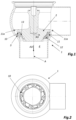
Figure 1 is a cross-sectional view of a fluid flow control valve having a valve disc and a valve seat, the valve disc supporting a valve disc gasket. -
Figure 2 is a view of the fluid flow control valve offigure 1 as seen from below infigure 1 . -
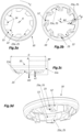
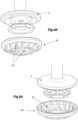
Figures 3a-d discloses a valve disc gasket in accordance with a first embodiment. -
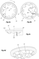
Figures 4a-d discloses a valve disc gasket in accordance with a second embodiment. -
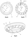
Figures 5a-c discloses a valve disc gasket in accordance with a third embodiment. -
Figures 6a-e discloses a valve disc gasket in accordance with a fourth embodiment, as such, and as installed on a fluid flow control valve having a hollow valve disc. -
Figures 7a-d discloses a valve disc gasket in accordance with a fifth embodiment, as such, and as installed on a fluid flow control valve having a hollow valve disc as infigures 6a-e . - In
figure 1 , there is in a cross-sectional view disclosed a fluidflow control valve 1 having avalve disc 2 and avalve seat 3. Thevalve seat 3 extends around aflow channel 4. Thevalve disc gasket 10 is attached to thevalve disc 2. Alternatively, it may be said that thevalve disc gasket 10 is supported by thevalve disc 2. Thevalve disc 2 and thevalve disc gasket 10 are configured to be moved into abutment with theseat 3, by moving thevalve disc 2 downwardly infigure 1 , and thereby close theflow channel 4. Thevalve disc 2 and thevalve disc gasket 10 are also configured to be moved a distance away from theseat 3, by moving thevalve disc 2 upwardly infigure 1 , and thereby open theflow channel 4. - By a valve disc gasket is meant a gasket that is attached to or supported by a valve disc as described above. The valve disc gasket is the gasket that closes the flow channel by abutment with the valve seat and the valve disc to obtain a closed state of the valve. The valve disc gasket also opens up the flow channel when placing the valve disc gasket and the valve disc at a distance from the valve seat to obtain an open state of the valve. The valve disc can alternatively be denoted for example valve plug, valve cone or sometimes valve body, in which cases the valve disc gasket can be denoted valve plug gasket, valve cone gasket or valve body gasket. The valve disc need not be disc shaped but can have any suitable shape closing (and opening up) the flow channel as long as the valve disc gasket fits thereon.
- The
valve disc gasket 10 fits loosely on thevalve disc 2 when thevalve disc 2 andvalve disc gasket 10 has been moved a distance away from theseat 3 allowing thevalve disc gasket 10 to rotate a plurality of revolutions on saidvalve disc 2 of said fluidflow control valve 1 and thereby permitting the fluidflow control valve 1 to be cleaned in place by flushing cleaning fluid amongst others through clearances between thevalve disc 2 and thevalve disc gasket 10. As will be disclosed in more detail below, thevalve disc gasket 10 is provided with a plurality of vane surfaces 25 such that it may be cleaned in accordance with a method comprising; introducing a cleaning liquid in aflow channel 4 such that a flow of cleaning liquid may be maintained during a cleaning period, and moving thevalve disc 2 and thevalve disc gasket 10 attached thereto in close proximity to theseat 3, whereby a flow of cleaning liquid will interact with the vane surfaces 25 such that thevalve disc gasket 10 is subjected to a torque around the axis A thereby causing thevalve disc gasket 10 to rotate several revolutions about the axis A relative to thevalve disc 2. - As disclosed in the figures, the
valve disc gasket 10 comprises basically a frustoconical, ring-shapedbody part 11 having a plurality of circumferentially distributed asymmetrical, through-goingopenings 21 and/or a plurality of circumferentially distributed asymmetrical through-goingslits 22 and/or a plurality of circumferentially distributedasymmetrical protrusions 23. In more detail, it may be said that aninternal surface opening 21 and/or asymmetrical through-going slit 22 forms avane surface 25 and/or wherein anexternal surface 23a of the respectiveasymmetrical protrusion 23 forms avane surface 25, wherein the through-goingopenings 21 and/or slits 22 and/orprotrusions 23 are asymmetrical at least in the sense that respective through-goingopening 21 or slit 22 and/orprotrusion 23 is asymmetric relative to any radial plane RP intersecting the respective through-goingopening 21 or slit 22 and/or therespective protrusion 23. - In
figures 3a-d , there is disclosed a design of avalve disc gasket 10 comprising a plurality ofasymmetrical slits 22 having vane surfaces 25 and a plurality ofasymmetrical protrusions 23 having vane surfaces 25. - In
figures 4a-d , there is disclosed a design of avalve disc gasket 10 comprising a plurality ofasymmetrical slits 22 having vane surfaces 25 of the same kind as infigures 3a-d , but without theasymmetrical protrusions 23. - As shown in
figure 4b , thevalve disc gaskets 10 offigures 3a-d and4a-d both comprises a plurality ofasymmetrical slits 22 distributed along the circular circumferential direction C. The slits 22 extend from an innercircular surface 14 of the frustoconical, ring-shapedbody part 11, at least with a component along a respective radial plane RP, and through the frustoconical, ring-shapedbody part 11 from thefront wall surface 12 to therear wall surface 13. Theslits 22 areasymmetrical slits 22 and have aninternal surface 22a being provided with or formed as avane surface 25. - The
valve disc gasket 10 offigures 3a-d also comprises a plurality ofasymmetric protrusions 23 distributed along the circular circumferential direction C. Eachprotrusion 23 extends from thefront wall surface 12 of the frustoconical, ring-shapedbody part 11 with a component v1 along the axial direction AD and has anexternal surface 23a forming at least one of said vane surfaces 25. - The asymmetrical through-going
slits 22 andasymmetrical protrusions 23 are asymmetrical at least in the sense that respective through-goingslit 22 andprotrusion 23 is asymmetric relative to any radial plane RP intersecting the respective asymmetrical through-goingslit 22 or the respectiveasymmetrical protrusion 23. In the figures, a central radial plane RP is consistently depicted. However, the phrase - any radial plane RP intersecting the respective asymmetrical through-goingslit 22 and/or the respective asymmetrical protrusion 23 - refers to a number of radial planes having slightly different angles and all extending from the axis A and intersecting therespective slit 22 orprotrusion 23. The same applies to the asymmetrical through-goingopenings 21 introduced with reference tofigures 6a-e . - As shown e.g. in
figures 3b and5b in respect of theasymmetrical protrusions 23, and as shown e.g. infigure 4b in respect of theasymmetrical slits 22, eachvane surface 25 forms an angle α with the radial plane RP intersecting the respective through-goingopening 21 or slit 22 and/or therespective protrusion 23 as seen in a plane having the axial direction AD as normal direction. The angle α is preferably at least 10 degrees relative to the central radial plane RP. More preferably the angle α is at least 20 degrees. Even more preferably the angle α is at least 25 degrees. Preferably the angle α is less than 55 degrees. More preferably the angle α is less than 45 degrees. Thus, the angle α may e.g. be between 10 and 55 degrees. According to one preferred embodiment the angle α is between 20 and 55 degrees. According to another preferred embodiment the angle α is between 25 and 55 degrees. According to another preferred embodiment the angle α is between 10 and 45 degrees. According to another preferred embodiment the angle α is between 20 and 45 degrees. According to another preferred embodiment the angle α is between 25 and 45 degrees. According to another preferred embodiment the angle α is between 10 and 40 degrees. According to another preferred embodiment the angle α is between 20 and 40 degrees. According to another preferred embodiment the angle α is between 25 and 40 degrees. According to another preferred embodiment the angle α is between 35 and 40 degrees. These preferred angles are applicable also to the other embodiments directly and indirectly disclosed throughout the description and the figures. - In
figures 5a-c , there is disclosed a design comprising a plurality ofslits 24 distributed along the circular circumferential direction C. The slits 24 extend from an innercircular surface 14 of the frustoconical, ring-shapedbody part 11, at least with a component along a respective radial plane RP, and through the frustoconical, ring-shapedbody part 11 from thefront wall surface 12 to therear wall surface 13. It may in this context be noted that theseslits 24 are notasymmetrical slits 22 providing vane surfaces 25 but are provided for the purpose of facilitating installation of thevalve disc gasket 10 onto thevalve disc 2 and/or for facilitating removal of thevalve disc gasket 10 from thevalve disc 2. The design infigures 5a-c also comprises a plurality ofasymmetrical protrusions 23 similar to the ones disclosed with reference tofigures 3a-d . However, it may be noted that theasymmetrical protrusions 23 infigures 3a-d will result in that thevalve disc gasket 10 will as seen infigure 3b rotate in clockwise direction whereas the asymmetrical protrusions infigures 5a-c will result in that thevalve disc gasket 10 will as seen infigure 5b rotate in counter-clockwise direction. - In f
igures 6a-e , there is disclosed a design in which thevalve disc gasket 10 comprises a plurality of asymmetrical through-goingopenings 21 distributed along the circular circumferential direction C. Each through-goingopening 21 extends from thefront wall surface 12 to therear wall surface 13 of the frustoconical, ring-shapedbody part 11 and has aninternal surface 21a forming at least one of said vane surfaces 25. In this design there is not provided anyslits protrusions 23. However, it is conceivable that this design may be provided withslits 24 facilitating installation and removal and/or be provided withasymmetrical slits 22. Theslits openings 21.Such slits opening 21 or e.g. interlaced after two or more, such as after two, three, or fourconsecutive openings 21. - In
figures 6a and6d-e it is shown avalve disc 2 being hollow. Such a design facilitates cleaning since it is easier to direct a flow of cleaning fluid into the clearances between thevalve disc 2 and thevalve disc gasket 10. - It may in this context be noted that the different
valve disc gaskets 10, directly or indirectly disclosed in the figures and in the description, may be combined with avalve disc 2 as disclosed infigure 1 or with ahollow valve disc 2 as disclosed infigures 6a ,6d-e . It is also conceivable that thevalve disc 2 may be designed differently from what is disclosed infigures 1 and6a ,6d-e . However, a common design criterium is that it should preferably be designed such that thevalve disc gasket 10 may rotate about thevalve disc 2 such that the provision ofasymmetrical openings 21 and/or slits 22 and/orprotrusions 23 may result in a rotation of thevalve disc gasket 10 relative to thevalve disc 2. - In
figures 7a-d , there is disclosed a design similar to the design offigures 6a-e . However, in thevalve disc gasket 10 shown infigures 7a-d , theopenings 21 offigures 6a-e has been designed asslits 22 extending from the innercircular surface 14 similarly as theslits 22 disclosed infigures 3a-d and 4a-d. Thus, although theslits 22 offigures 7a-d are narrower, they are also asymmetrical and provided withvane surfaces 25 in the same basic manner as theslits 22 offigures 3a-d and4a-d . - Irrespective of if the
vane surface 25 are provided onasymmetrical openings 21 orasymmetrical slits 22 orasymmetrical protrusions 23, eachvane surface 25 has a major surface extension having a normal with a component along the circular circumferential direction C. This may in more detail by said as that eachvane surface 25 has a major surface extension defined by a vector v1 having at least a component, preferably a major component, along the axial direction AD and by a vector v2 extending in a direction extending transversely to the axial direction and being inclined in a first direction relative to any radial plane RP intersecting the respective asymmetrical through-goingopening 12 and/or slit 22 and/or therespective protrusion 23. - As e.g. shown in
figures 3d ,4d ,5c ,6c , and7b , therear wall surface 13 is shaped as a raceway allowing thevalve disc gasket 10 to rotate a plurality of revolutions on saidvalve disc 2 of said fluidflow control valve 1. - The vane surfaces 25, which may be provided on
asymmetrical openings 21 and/orasymmetrical slits 22 and/orasymmetrical protrusions 23, when taken together has a total surface area being x times y mm2, where x is at least three, preferably at least four, and y is a largest outer diameter D in millimetre of a sealingportion 12a of thevalve disc gasket 10. The largest outer diameter D may e.g. be in the order of about 30-150 mm. For a 1-inch valve, the largest outer diameter D may typically be about 44 mm. For a 1.5-inch valve, the largest outer diameter D may typically be about 54 mm. For a 2-inch valve, the largest outer diameter D may typically be about 57 mm. For a 2.5-inch valve, the largest outer diameter D may typically be about 73 mm. For a 3-inch valve, the largest outer diameter D may typically be about 88 mm. For a 4-inch valve, the largest outer diameter D may typically be about 107 mm. - Each
vane surface 25 preferably has an extension of at least 2 mm along the axial direction AD, more preferably an extension of at least 4 mm along the axial direction AD. The vane surfaces 25 preferably has an extension of at most 15 mm, more preferably at most 10 mm, even more preferably at most 5 mm along the axial direction AD. The vane surfaces 25 typically has an extension of 4-5 mm along the axial direction AD. - It is contemplated that there are numerous modifications of the embodiments described herein, which are still within the scope of the invention as defined by the appended claims.
- It may explicitly be noted that the
valve disc gasket 10 may be provided with a) asymmetrical through-goingopenings 21 providing vane surfaces 25, and/or b) asymmetrical through-goingslits 22 providing vane surfaces 25, and/or c)asymmetrical protrusions 23 providing vane surfaces 25, in any combination including only one, two, three or all four of these features in any permutation conceivable. - It may also be noted that in case the
valve disc gasket 10 is provided withasymmetrical protrusions 23 having vane surfaces in combination with thevalve disc gasket 10 also having through-goingasymmetrical openings 21 and/or through-goingasymmetrical slits 22, the vane surfaces 25 of theprotrusions 23 may be circumferentially separated from the vane surfaces of theopenings 21 and/or slits 22 as shown in the figures or may be formed such that thevane surface 25 of theprotrusions 23 continues to form avane surface 25 of theopenings 21 and/or slits 22. It is also conceivable to have avalve disc gasket 10 with a combination of this, i.e. withvane surfaces 25 of someprotrusions 23 circumferentially separated from the vane surfaces 25 of neighbouringopenings 21 and/or slits 22 and vane surfaces 25 of someprotrusions 23 being formed continuous with the vane surfaces of neighbouringopenings 21 and/or slits 22.
Claims (13)
- Fluid flow control valve (1) comprisinga valve disc (2),a valve disc gasket (10) attached to the valve disc (2), anda valve seat (3) extending around a flow channel (4),wherein the valve disc (2) and the valve disc gasket (10) are configured to be moved into abutment with the seat (3) and thereby close the flow channel (4) and to be moved a distance away from the seat (3) and thereby open the flow channel (4),the valve disc gasket (10) comprisinga frustoconical, ring-shaped body part (11) having a geometrical main extension along a circular circumferential direction (C) around an axis (A) extending along an axial direction (AD), wherein a cross-sectional shape of the frustoconical, ring-shaped body part (11), as seen in a radial plane (RP), has a geometrical main extension being inclined relative to the axial direction (AD) with a component along the axial direction (AD) and with a component along a radial direction (RD), such that the frustoconical, ring-shaped body part (11) extends along a geometrical frustoconical envelope surface (11a) tapering in the axial direction (AD), wherein the frustoconical, ring-shaped body part (11) has an outwardly facing front wall surface (12) facing with a component along the axial direction (AD) and an inwardly facing rear wall surface (13), opposite the front wall surface (12), the rear wall surface (13) facing the valve disc (2) of said fluid flow control valve (1),characterised in thatvalve disc gasket (10) further comprisesa) a plurality of asymmetrical through-going openings (21) and/or slits (22) extending from the front wall surface (12) to the rear wall surface (13) of the frustoconical, ring-shaped body part (11), the asymmetrical through-going openings (21) and/or slits (22) being distributed along the circular circumferential direction (C), wherein an internal surface (21a, 22a) of the respective asymmetrical through-going opening (21) and/or slit (22) forms a vane surface (25), and/orb) a plurality of asymmetrical protrusions (23) having an extension from the front wall surface (12) of the frustoconical, ring-shaped body part (11) with a component along the axial direction (AD), the asymmetrical protrusions (23) being distributed along the circular circumferential direction (C), wherein an external surface (23a) of the respective protrusion (23) forms a vane surface (25),wherein the asymmetrical through-going openings (21) and/or slits (22) and/or asymmetrical protrusions (23) are asymmetrical at least in the sense that respective through-going opening (21) or slit (22) and/or protrusion (23) is asymmetric relative to any radial plane (RP) intersecting the respective through-going opening (21) or slit (22) and/or the respective protrusion (23), andwherein the valve disc gasket (10) fits loosely on the valve disc (2) when the valve disc (2) and valve disc gasket (10) has been moved a distance away from the seat (3) allowing the valve disc gasket (10) to rotate a plurality of revolutions on said valve disc (2) of said fluid flow control valve (1) and thereby permitting the fluid flow control valve (1) to be cleaned in place by flushing cleaning fluid amongst others through clearances between the valve disc (2) and the valve disc gasket (10).
- Fluid flow control valve (1) according to claim 1, wherein each vane surface (25) forms an angle (α) with any radial plane (RP) intersecting the respective through-going opening (21) or slit (22) and/or the respective protrusion (23) as seen in a plane having the axial direction (AD) as normal direction, the angle (α) preferably being at least 10 degrees, more preferably at least 15 degrees, relative to a central radial plane (RP).
- Fluid flow control valve (1) according to claim 1 or 2, wherein each vane surface (25) has a major surface extension having a normal with a component along the circular circumferential direction (C).
- Fluid flow control valve (1) according to any one of claims 1-3,
wherein each vane surface (25) has a major surface extension defined by a vector (v1) having at least a component, preferably a major component, along the axial direction (AD) and by a vector (v2) extending in a direction extending transversely to the axial direction and being inclined in a first direction relative to any radial plane (RP) intersecting the respective through-going opening (12) or slit (22) and/or the respective protrusion (23). - Fluid flow control valve (1) according to any one of claims 1-4,
wherein the valve disc gasket (10) comprises a plurality of slits (22, 24) distributed along the circular circumferential direction (C), the slits (22, 24) extending from an inner circular surface (14) of the frustoconical, ring-shaped body part (11), at least with a component along a respective radial plane (RP), and through the frustoconical, ring-shaped body part (11) from the front wall surface (12) to the rear wall surface (13). - Fluid flow control valve (1) according to claim 5, wherein at least a sub-set of the plurality of slits (22) are asymmetrical slits (22) having an internal surface (22a) being provided with a respective one of said vane surfaces (25).
- Fluid flow control valve (1) according to any one of claims 1-6,
wherein the valve disc gasket (10) comprises a plurality of asymmetrical protrusions (23) distributed along the circular circumferential direction (C), wherein each protrusion (23) extends from the front wall surface (12) of the frustoconical, ring-shaped body part (11) with a component along the axial direction (AD) and has an external surface (23a) forming at least one of said vane surfaces (25). - Fluid flow control valve (1) according to any one of claims 1-4,wherein the valve disc gasket (10) comprises a plurality of slits (22, 24) distributed along the circular circumferential direction (C), the slits (22, 24) extending from an inner circular surface (14) of the frustoconical, ring-shaped body part (11), at least with a component along a respective radial plane (RP), and through the frustoconical, ring-shaped body part (11) from the front wall surface (12) to the rear wall surface (13),wherein at least a sub-set of the plurality of slits (22) are asymmetrical slits (22) having an internal surface (22a) being provided with at least one of said vane surfaces (25), andwherein the valve disc gasket (10) comprises a plurality of asymmetrical protrusions (23) distributed along the circular circumferential direction (C), wherein each protrusion (23) extends from the front wall surface (12) of the frustoconical, ring-shaped body part (11) with a component along the axial direction (AD) and has an external surface (23a) forming at least one of said vane surfaces (25).
- Fluid flow control valve (1) according to any one of clams 1-6, wherein the valve disc gasket (10) comprises a plurality of asymmetrical through-going openings (21) distributed along the circular circumferential direction (C), wherein each asymmetrical through-going opening (21) extends from the front wall surface (12) to the rear wall surface (13) of the frustoconical, ring-shaped body part (11) and has an internal surface (21a) forming at least one of said vane surfaces (25).
- Fluid flow control valve (1) according to any one of claims 1-4,wherein the valve disc gasket (10) comprises a plurality of slits (22, 24) distributed along the circular circumferential direction (C), the slits (22, 24) extending from an inner circular surface (14) of the frustoconical, ring-shaped body part (11), at least with a component along a respective radial plane (RP), and through the frustoconical, ring-shaped body part (11) from the front wall surface (12) to the rear wall surface (13),wherein at least a sub-set of the plurality of slits (22) are asymmetrical slits (22) having an internal surface (22a) being provided with at least one of said vane surfaces (25), andwherein the valve disc gasket (10) comprises a plurality of asymmetrical through-going openings (21) distributed along the circular circumferential direction (C), wherein each asymmetrical through-going opening (21) extends from the front wall surface (12) to the rear wall surface (13) of the frustoconical, ring-shaped body part (11) and has an internal surface (21a) forming at least one of said vane surfaces (25).
- Fluid flow control valve (1) according to any one of claims 1-6,wherein the valve disc gasket (10) comprises a plurality of asymmetrical protrusions (23) distributed along the circular circumferential direction (C), wherein each protrusion (23) extends from the front wall surface (12) of the frustoconical, ring-shaped body part (11) with a component along the axial direction (AD) and has an external surface (23a) forming at least one of said vane surfaces (25), andwherein the valve disc gasket (10) comprises a plurality of asymmetrical through-going openings (21) distributed along the circular circumferential direction (C), wherein each asymmetrical through-going opening (21) extends from the front wall surface (12) to the rear wall surface (13) of the frustoconical, ring-shaped body part (11) and has an internal surface (21a) forming at least one of said vane surfaces (25).
- Fluid flow control valve (1) according to any one of claims 1-11, wherein the rear wall surface (13) is shaped as a raceway.
- Method of cleaning a fluid flow control valve (1) according to any one of claims 1-12, comprisingintroducing a cleaning liquid in the flow channel (4) such that a flow of cleaning liquid may be maintained during a cleaning period,moving the valve disc (2) and the valve disc gasket (10) attached thereto in close proximity to the seat (3), whereby a flow of cleaning liquid will interact with the vane surfaces (25) such that the valve disc gasket (10) is subjected to a torque around the axis (A) thereby causing the valve disc gasket (10) to rotate several revolutions about the axis (A) relative to the valve disc (2).
Applications Claiming Priority (2)
| Application Number | Priority Date | Filing Date | Title |
|---|---|---|---|
| EP19196438.6A EP3792527A1 (en) | 2019-09-10 | 2019-09-10 | Gasket, fluid flow control valve and method of cleaning such a valve |
| PCT/EP2020/075086 WO2021048130A1 (en) | 2019-09-10 | 2020-09-08 | Gasket, fluid flow control valve and method of cleaning such a valve |
Publications (2)
| Publication Number | Publication Date |
|---|---|
| EP4028682A1 EP4028682A1 (en) | 2022-07-20 |
| EP4028682B1 true EP4028682B1 (en) | 2024-07-17 |
Family
ID=67909351
Family Applications (2)
| Application Number | Title | Priority Date | Filing Date |
|---|---|---|---|
| EP19196438.6A Withdrawn EP3792527A1 (en) | 2019-09-10 | 2019-09-10 | Gasket, fluid flow control valve and method of cleaning such a valve |
| EP20765055.7A Active EP4028682B1 (en) | 2019-09-10 | 2020-09-08 | Gasket, fluid flow control valve and method of cleaning such a valve |
Family Applications Before (1)
| Application Number | Title | Priority Date | Filing Date |
|---|---|---|---|
| EP19196438.6A Withdrawn EP3792527A1 (en) | 2019-09-10 | 2019-09-10 | Gasket, fluid flow control valve and method of cleaning such a valve |
Country Status (4)
| Country | Link |
|---|---|
| US (1) | US12104702B2 (en) |
| EP (2) | EP3792527A1 (en) |
| CN (1) | CN114616413B (en) |
| WO (1) | WO2021048130A1 (en) |
Families Citing this family (2)
| Publication number | Priority date | Publication date | Assignee | Title |
|---|---|---|---|---|
| CN114453286B (en) * | 2022-01-04 | 2023-01-17 | 吉林大学重庆研究院 | Automatic production line and production process for hydraulic cylinder |
| EP4464651A1 (en) * | 2023-05-15 | 2024-11-20 | MBF S.p.A. | Valve assembly for a filling machine and filling machine provided with such a valve |
Family Cites Families (20)
| Publication number | Priority date | Publication date | Assignee | Title |
|---|---|---|---|---|
| US865798A (en) | 1907-01-16 | 1907-09-10 | John Peterson | Valve. |
| US2084210A (en) | 1936-11-03 | 1937-06-15 | American Stove Co | Gas cock |
| GB726289A (en) * | 1953-07-21 | 1955-03-16 | James Cicero Ross | Faucet |
| DE2330168A1 (en) * | 1973-06-14 | 1975-01-02 | Robert Williams Hengesbach | Self-cleaning conical calve closure element - has spring loaded cone with O-ring in recess movable axially to conical seat |
| CA1008055A (en) * | 1973-10-01 | 1977-04-05 | Rockwell International Corporation | Valve with improved flow passage |
| DE2524940C3 (en) * | 1975-06-05 | 1980-03-20 | Joh. Vaillant Gmbh U. Co, 5630 Remscheid | Low-noise lift valve |
| US4531532A (en) | 1983-09-02 | 1985-07-30 | Ladish Co. | Snap-on valve gasket |
| US5358212A (en) * | 1993-10-08 | 1994-10-25 | Copes-Vulcan, Inc. | Poppet valve having external adjustment for a flow restrictor |
| DE69625344T2 (en) | 1996-07-15 | 2003-09-18 | Toyo Stainless Steel Industries Co., Ltd. | Double seat valve |
| US5996966A (en) | 1998-04-02 | 1999-12-07 | Tri-Clover, Inc. | Snap-on valve gasket |
| US6056270A (en) | 1998-05-13 | 2000-05-02 | Tri-Clover, Inc. | Valve gasket formed of composite materials and process |
| CA2447872A1 (en) * | 2001-06-13 | 2002-12-19 | Garlock Sealing Technologies Llc | Pump bushing device and associated methods |
| GB0211268D0 (en) | 2002-05-17 | 2002-06-26 | L & L Products Inc | Hole plugs |
| US7441564B2 (en) * | 2005-06-06 | 2008-10-28 | Tescom Corporation | Gas cylinder valve assembly |
| DE102005057103A1 (en) | 2005-11-25 | 2007-05-31 | Südmo Holding GmbH | Aseptic valve device for separation of hostile media in food industry, has valve disk with drainage section that extends to plane such that opening cross-section of drainage openings is larger than cross-section of connection opening |
| US8256462B2 (en) | 2008-09-02 | 2012-09-04 | Emerson Process Management Regulator Technologies, Inc. | Fluid flow control members for use with valves |
| US10274099B2 (en) * | 2016-02-10 | 2019-04-30 | Emerson Process Management Regulator Technologies Tulsa, Llc | Spring actuated thermal valve |
| EP3207996B1 (en) | 2016-02-22 | 2019-05-08 | Alfa Laval Corporate AB | A centrifuge rotor for a centrifugal separator, a centrifugal separator, a method of separation, and a conical disk |
| EP3470352B1 (en) * | 2017-10-10 | 2023-08-09 | Coperion GmbH | Points for transporting transported goods and method for cleaning points |
| CN108061167B (en) * | 2017-12-28 | 2024-02-23 | 宙斯流体系统(上海)有限公司 | Fluid injection device capable of adjusting flow |
-
2019
- 2019-09-10 EP EP19196438.6A patent/EP3792527A1/en not_active Withdrawn
-
2020
- 2020-09-08 WO PCT/EP2020/075086 patent/WO2021048130A1/en not_active Ceased
- 2020-09-08 EP EP20765055.7A patent/EP4028682B1/en active Active
- 2020-09-08 US US17/639,721 patent/US12104702B2/en active Active
- 2020-09-08 CN CN202080077175.6A patent/CN114616413B/en active Active
Also Published As
| Publication number | Publication date |
|---|---|
| US20220333693A1 (en) | 2022-10-20 |
| EP3792527A1 (en) | 2021-03-17 |
| CN114616413B (en) | 2023-10-13 |
| EP4028682A1 (en) | 2022-07-20 |
| CN114616413A (en) | 2022-06-10 |
| US12104702B2 (en) | 2024-10-01 |
| WO2021048130A1 (en) | 2021-03-18 |
Similar Documents
| Publication | Publication Date | Title |
|---|---|---|
| US12104702B2 (en) | Gasket, fluid flow control valve and method of cleaning such a valve | |
| US5996966A (en) | Snap-on valve gasket | |
| US4531532A (en) | Snap-on valve gasket | |
| EP2816266B1 (en) | Double seat valve | |
| US20030041905A1 (en) | Check valve and method of fabrication | |
| US4290454A (en) | Back flow valve | |
| US5435521A (en) | Ball valve with rinsing action | |
| CN213271519U (en) | Water outlet device | |
| CN204961893U (en) | Special ball valve of silica flour tail gas | |
| WO2018109258A1 (en) | Distributor valve body for a vacuum filter, a combination and a vacuum filter having such a distribution valve body, and methods related thereto | |
| GB2481921A (en) | Fluid control valve | |
| US5088688A (en) | Fixed plate for a hydraulic valve, provided with means for ejecting chips | |
| US4357959A (en) | Back flow valve | |
| JP2015224686A (en) | Double eccentric butterfly valve | |
| US12203560B2 (en) | Axial multi-stage, multi-path control valve element design for external plugs | |
| CN111630306B (en) | Process control valve | |
| JP2000283306A (en) | Ball valve | |
| JP6833181B2 (en) | Water supply hose fitting | |
| CN114719036B (en) | Constant flow valve | |
| KR100579879B1 (en) | Disc Seat Floating Butterfly Valve | |
| JP5583719B2 (en) | Dishwasher that rotates brush by water pressure of tap water | |
| CN119178045A (en) | Rotary water separator | |
| KR101370099B1 (en) | Cone valve with handle | |
| CN210218836U (en) | Self-closing valve | |
| JP2001336645A (en) | Ball valve |
Legal Events
| Date | Code | Title | Description |
|---|---|---|---|
| STAA | Information on the status of an ep patent application or granted ep patent |
Free format text: STATUS: UNKNOWN |
|
| STAA | Information on the status of an ep patent application or granted ep patent |
Free format text: STATUS: THE INTERNATIONAL PUBLICATION HAS BEEN MADE |
|
| PUAI | Public reference made under article 153(3) epc to a published international application that has entered the european phase |
Free format text: ORIGINAL CODE: 0009012 |
|
| STAA | Information on the status of an ep patent application or granted ep patent |
Free format text: STATUS: REQUEST FOR EXAMINATION WAS MADE |
|
| 17P | Request for examination filed |
Effective date: 20220408 |
|
| AK | Designated contracting states |
Kind code of ref document: A1 Designated state(s): AL AT BE BG CH CY CZ DE DK EE ES FI FR GB GR HR HU IE IS IT LI LT LU LV MC MK MT NL NO PL PT RO RS SE SI SK SM TR |
|
| DAV | Request for validation of the european patent (deleted) | ||
| DAX | Request for extension of the european patent (deleted) | ||
| GRAP | Despatch of communication of intention to grant a patent |
Free format text: ORIGINAL CODE: EPIDOSNIGR1 |
|
| STAA | Information on the status of an ep patent application or granted ep patent |
Free format text: STATUS: GRANT OF PATENT IS INTENDED |
|
| INTG | Intention to grant announced |
Effective date: 20240306 |
|
| GRAS | Grant fee paid |
Free format text: ORIGINAL CODE: EPIDOSNIGR3 |
|
| P01 | Opt-out of the competence of the unified patent court (upc) registered |
Effective date: 20240508 |
|
| GRAA | (expected) grant |
Free format text: ORIGINAL CODE: 0009210 |
|
| STAA | Information on the status of an ep patent application or granted ep patent |
Free format text: STATUS: THE PATENT HAS BEEN GRANTED |
|
| AK | Designated contracting states |
Kind code of ref document: B1 Designated state(s): AL AT BE BG CH CY CZ DE DK EE ES FI FR GB GR HR HU IE IS IT LI LT LU LV MC MK MT NL NO PL PT RO RS SE SI SK SM TR |
|
| REG | Reference to a national code |
Ref country code: CH Ref legal event code: EP |
|
| REG | Reference to a national code |
Ref country code: DE Ref legal event code: R096 Ref document number: 602020034159 Country of ref document: DE |
|
| REG | Reference to a national code |
Ref country code: IE Ref legal event code: FG4D |
|
| REG | Reference to a national code |
Ref country code: LT Ref legal event code: MG9D |
|
| REG | Reference to a national code |
Ref country code: NL Ref legal event code: MP Effective date: 20240717 |
|
| PG25 | Lapsed in a contracting state [announced via postgrant information from national office to epo] |
Ref country code: PT Free format text: LAPSE BECAUSE OF FAILURE TO SUBMIT A TRANSLATION OF THE DESCRIPTION OR TO PAY THE FEE WITHIN THE PRESCRIBED TIME-LIMIT Effective date: 20241118 |
|
| REG | Reference to a national code |
Ref country code: AT Ref legal event code: MK05 Ref document number: 1704424 Country of ref document: AT Kind code of ref document: T Effective date: 20240717 |
|
| PG25 | Lapsed in a contracting state [announced via postgrant information from national office to epo] |
Ref country code: NL Free format text: LAPSE BECAUSE OF FAILURE TO SUBMIT A TRANSLATION OF THE DESCRIPTION OR TO PAY THE FEE WITHIN THE PRESCRIBED TIME-LIMIT Effective date: 20240717 |
|
| PG25 | Lapsed in a contracting state [announced via postgrant information from national office to epo] |
Ref country code: PT Free format text: LAPSE BECAUSE OF FAILURE TO SUBMIT A TRANSLATION OF THE DESCRIPTION OR TO PAY THE FEE WITHIN THE PRESCRIBED TIME-LIMIT Effective date: 20241118 Ref country code: NL Free format text: LAPSE BECAUSE OF FAILURE TO SUBMIT A TRANSLATION OF THE DESCRIPTION OR TO PAY THE FEE WITHIN THE PRESCRIBED TIME-LIMIT Effective date: 20240717 |
|
| PG25 | Lapsed in a contracting state [announced via postgrant information from national office to epo] |
Ref country code: NO Free format text: LAPSE BECAUSE OF FAILURE TO SUBMIT A TRANSLATION OF THE DESCRIPTION OR TO PAY THE FEE WITHIN THE PRESCRIBED TIME-LIMIT Effective date: 20241017 |
|
| PG25 | Lapsed in a contracting state [announced via postgrant information from national office to epo] |
Ref country code: PL Free format text: LAPSE BECAUSE OF FAILURE TO SUBMIT A TRANSLATION OF THE DESCRIPTION OR TO PAY THE FEE WITHIN THE PRESCRIBED TIME-LIMIT Effective date: 20240717 Ref country code: GR Free format text: LAPSE BECAUSE OF FAILURE TO SUBMIT A TRANSLATION OF THE DESCRIPTION OR TO PAY THE FEE WITHIN THE PRESCRIBED TIME-LIMIT Effective date: 20241018 Ref country code: FI Free format text: LAPSE BECAUSE OF FAILURE TO SUBMIT A TRANSLATION OF THE DESCRIPTION OR TO PAY THE FEE WITHIN THE PRESCRIBED TIME-LIMIT Effective date: 20240717 |
|
| PG25 | Lapsed in a contracting state [announced via postgrant information from national office to epo] |
Ref country code: BG Free format text: LAPSE BECAUSE OF FAILURE TO SUBMIT A TRANSLATION OF THE DESCRIPTION OR TO PAY THE FEE WITHIN THE PRESCRIBED TIME-LIMIT Effective date: 20240717 |
|
| PG25 | Lapsed in a contracting state [announced via postgrant information from national office to epo] |
Ref country code: LV Free format text: LAPSE BECAUSE OF FAILURE TO SUBMIT A TRANSLATION OF THE DESCRIPTION OR TO PAY THE FEE WITHIN THE PRESCRIBED TIME-LIMIT Effective date: 20240717 |
|
| PG25 | Lapsed in a contracting state [announced via postgrant information from national office to epo] |
Ref country code: IS Free format text: LAPSE BECAUSE OF FAILURE TO SUBMIT A TRANSLATION OF THE DESCRIPTION OR TO PAY THE FEE WITHIN THE PRESCRIBED TIME-LIMIT Effective date: 20241117 Ref country code: AT Free format text: LAPSE BECAUSE OF FAILURE TO SUBMIT A TRANSLATION OF THE DESCRIPTION OR TO PAY THE FEE WITHIN THE PRESCRIBED TIME-LIMIT Effective date: 20240717 |
|
| PG25 | Lapsed in a contracting state [announced via postgrant information from national office to epo] |
Ref country code: HR Free format text: LAPSE BECAUSE OF FAILURE TO SUBMIT A TRANSLATION OF THE DESCRIPTION OR TO PAY THE FEE WITHIN THE PRESCRIBED TIME-LIMIT Effective date: 20240717 |
|
| PG25 | Lapsed in a contracting state [announced via postgrant information from national office to epo] |
Ref country code: ES Free format text: LAPSE BECAUSE OF FAILURE TO SUBMIT A TRANSLATION OF THE DESCRIPTION OR TO PAY THE FEE WITHIN THE PRESCRIBED TIME-LIMIT Effective date: 20240717 Ref country code: RS Free format text: LAPSE BECAUSE OF FAILURE TO SUBMIT A TRANSLATION OF THE DESCRIPTION OR TO PAY THE FEE WITHIN THE PRESCRIBED TIME-LIMIT Effective date: 20241017 |
|
| PG25 | Lapsed in a contracting state [announced via postgrant information from national office to epo] |
Ref country code: RS Free format text: LAPSE BECAUSE OF FAILURE TO SUBMIT A TRANSLATION OF THE DESCRIPTION OR TO PAY THE FEE WITHIN THE PRESCRIBED TIME-LIMIT Effective date: 20241017 Ref country code: PL Free format text: LAPSE BECAUSE OF FAILURE TO SUBMIT A TRANSLATION OF THE DESCRIPTION OR TO PAY THE FEE WITHIN THE PRESCRIBED TIME-LIMIT Effective date: 20240717 Ref country code: NO Free format text: LAPSE BECAUSE OF FAILURE TO SUBMIT A TRANSLATION OF THE DESCRIPTION OR TO PAY THE FEE WITHIN THE PRESCRIBED TIME-LIMIT Effective date: 20241017 Ref country code: LV Free format text: LAPSE BECAUSE OF FAILURE TO SUBMIT A TRANSLATION OF THE DESCRIPTION OR TO PAY THE FEE WITHIN THE PRESCRIBED TIME-LIMIT Effective date: 20240717 Ref country code: IS Free format text: LAPSE BECAUSE OF FAILURE TO SUBMIT A TRANSLATION OF THE DESCRIPTION OR TO PAY THE FEE WITHIN THE PRESCRIBED TIME-LIMIT Effective date: 20241117 Ref country code: HR Free format text: LAPSE BECAUSE OF FAILURE TO SUBMIT A TRANSLATION OF THE DESCRIPTION OR TO PAY THE FEE WITHIN THE PRESCRIBED TIME-LIMIT Effective date: 20240717 Ref country code: GR Free format text: LAPSE BECAUSE OF FAILURE TO SUBMIT A TRANSLATION OF THE DESCRIPTION OR TO PAY THE FEE WITHIN THE PRESCRIBED TIME-LIMIT Effective date: 20241018 Ref country code: FI Free format text: LAPSE BECAUSE OF FAILURE TO SUBMIT A TRANSLATION OF THE DESCRIPTION OR TO PAY THE FEE WITHIN THE PRESCRIBED TIME-LIMIT Effective date: 20240717 Ref country code: ES Free format text: LAPSE BECAUSE OF FAILURE TO SUBMIT A TRANSLATION OF THE DESCRIPTION OR TO PAY THE FEE WITHIN THE PRESCRIBED TIME-LIMIT Effective date: 20240717 Ref country code: BG Free format text: LAPSE BECAUSE OF FAILURE TO SUBMIT A TRANSLATION OF THE DESCRIPTION OR TO PAY THE FEE WITHIN THE PRESCRIBED TIME-LIMIT Effective date: 20240717 Ref country code: AT Free format text: LAPSE BECAUSE OF FAILURE TO SUBMIT A TRANSLATION OF THE DESCRIPTION OR TO PAY THE FEE WITHIN THE PRESCRIBED TIME-LIMIT Effective date: 20240717 |
|
| PG25 | Lapsed in a contracting state [announced via postgrant information from national office to epo] |
Ref country code: DK Free format text: LAPSE BECAUSE OF FAILURE TO SUBMIT A TRANSLATION OF THE DESCRIPTION OR TO PAY THE FEE WITHIN THE PRESCRIBED TIME-LIMIT Effective date: 20240717 Ref country code: RO Free format text: LAPSE BECAUSE OF FAILURE TO SUBMIT A TRANSLATION OF THE DESCRIPTION OR TO PAY THE FEE WITHIN THE PRESCRIBED TIME-LIMIT Effective date: 20240717 Ref country code: SM Free format text: LAPSE BECAUSE OF FAILURE TO SUBMIT A TRANSLATION OF THE DESCRIPTION OR TO PAY THE FEE WITHIN THE PRESCRIBED TIME-LIMIT Effective date: 20240717 |
|
| REG | Reference to a national code |
Ref country code: DE Ref legal event code: R097 Ref document number: 602020034159 Country of ref document: DE |
|
| PG25 | Lapsed in a contracting state [announced via postgrant information from national office to epo] |
Ref country code: MC Free format text: LAPSE BECAUSE OF FAILURE TO SUBMIT A TRANSLATION OF THE DESCRIPTION OR TO PAY THE FEE WITHIN THE PRESCRIBED TIME-LIMIT Effective date: 20240717 Ref country code: EE Free format text: LAPSE BECAUSE OF FAILURE TO SUBMIT A TRANSLATION OF THE DESCRIPTION OR TO PAY THE FEE WITHIN THE PRESCRIBED TIME-LIMIT Effective date: 20240717 |
|
| PG25 | Lapsed in a contracting state [announced via postgrant information from national office to epo] |
Ref country code: CZ Free format text: LAPSE BECAUSE OF FAILURE TO SUBMIT A TRANSLATION OF THE DESCRIPTION OR TO PAY THE FEE WITHIN THE PRESCRIBED TIME-LIMIT Effective date: 20240717 |
|
| PG25 | Lapsed in a contracting state [announced via postgrant information from national office to epo] |
Ref country code: SK Free format text: LAPSE BECAUSE OF FAILURE TO SUBMIT A TRANSLATION OF THE DESCRIPTION OR TO PAY THE FEE WITHIN THE PRESCRIBED TIME-LIMIT Effective date: 20240717 |
|
| REG | Reference to a national code |
Ref country code: CH Ref legal event code: PL |
|
| PG25 | Lapsed in a contracting state [announced via postgrant information from national office to epo] |
Ref country code: LU Free format text: LAPSE BECAUSE OF NON-PAYMENT OF DUE FEES Effective date: 20240908 |
|
| PLBE | No opposition filed within time limit |
Free format text: ORIGINAL CODE: 0009261 |
|
| STAA | Information on the status of an ep patent application or granted ep patent |
Free format text: STATUS: NO OPPOSITION FILED WITHIN TIME LIMIT |
|
| 26N | No opposition filed |
Effective date: 20250422 |
|
| GBPC | Gb: european patent ceased through non-payment of renewal fee |
Effective date: 20241017 |
|
| PG25 | Lapsed in a contracting state [announced via postgrant information from national office to epo] |
Ref country code: GB Free format text: LAPSE BECAUSE OF NON-PAYMENT OF DUE FEES Effective date: 20241017 |
|
| REG | Reference to a national code |
Ref country code: BE Ref legal event code: MM Effective date: 20240930 |
|
| PG25 | Lapsed in a contracting state [announced via postgrant information from national office to epo] |
Ref country code: BE Free format text: LAPSE BECAUSE OF NON-PAYMENT OF DUE FEES Effective date: 20240930 |
|
| PG25 | Lapsed in a contracting state [announced via postgrant information from national office to epo] |
Ref country code: FR Free format text: LAPSE BECAUSE OF NON-PAYMENT OF DUE FEES Effective date: 20240917 |
|
| PG25 | Lapsed in a contracting state [announced via postgrant information from national office to epo] |
Ref country code: CH Free format text: LAPSE BECAUSE OF NON-PAYMENT OF DUE FEES Effective date: 20240930 |
|
| PG25 | Lapsed in a contracting state [announced via postgrant information from national office to epo] |
Ref country code: IE Free format text: LAPSE BECAUSE OF NON-PAYMENT OF DUE FEES Effective date: 20240908 |
|
| PG25 | Lapsed in a contracting state [announced via postgrant information from national office to epo] |
Ref country code: SE Free format text: LAPSE BECAUSE OF FAILURE TO SUBMIT A TRANSLATION OF THE DESCRIPTION OR TO PAY THE FEE WITHIN THE PRESCRIBED TIME-LIMIT Effective date: 20240717 |
|
| PGFP | Annual fee paid to national office [announced via postgrant information from national office to epo] |
Ref country code: DE Payment date: 20250702 Year of fee payment: 6 |
|
| PG25 | Lapsed in a contracting state [announced via postgrant information from national office to epo] |
Ref country code: CY Free format text: LAPSE BECAUSE OF FAILURE TO SUBMIT A TRANSLATION OF THE DESCRIPTION OR TO PAY THE FEE WITHIN THE PRESCRIBED TIME-LIMIT; INVALID AB INITIO Effective date: 20200908 Ref country code: IT Free format text: LAPSE BECAUSE OF FAILURE TO SUBMIT A TRANSLATION OF THE DESCRIPTION OR TO PAY THE FEE WITHIN THE PRESCRIBED TIME-LIMIT Effective date: 20240717 |
|
| PG25 | Lapsed in a contracting state [announced via postgrant information from national office to epo] |
Ref country code: HU Free format text: LAPSE BECAUSE OF FAILURE TO SUBMIT A TRANSLATION OF THE DESCRIPTION OR TO PAY THE FEE WITHIN THE PRESCRIBED TIME-LIMIT; INVALID AB INITIO Effective date: 20200908 |