EP4028665B1 - Centrifugal compressor and refrigerating device - Google Patents
Centrifugal compressor and refrigerating device Download PDFInfo
- Publication number
- EP4028665B1 EP4028665B1 EP20781144.9A EP20781144A EP4028665B1 EP 4028665 B1 EP4028665 B1 EP 4028665B1 EP 20781144 A EP20781144 A EP 20781144A EP 4028665 B1 EP4028665 B1 EP 4028665B1
- Authority
- EP
- European Patent Office
- Prior art keywords
- shell
- bearing
- centrifugal compressor
- fluid
- oil
- Prior art date
- Legal status (The legal status is an assumption and is not a legal conclusion. Google has not performed a legal analysis and makes no representation as to the accuracy of the status listed.)
- Active
Links
Images

Classifications
-
- F—MECHANICAL ENGINEERING; LIGHTING; HEATING; WEAPONS; BLASTING
- F04—POSITIVE - DISPLACEMENT MACHINES FOR LIQUIDS; PUMPS FOR LIQUIDS OR ELASTIC FLUIDS
- F04D—NON-POSITIVE-DISPLACEMENT PUMPS
- F04D17/00—Radial-flow pumps, e.g. centrifugal pumps; Helico-centrifugal pumps
- F04D17/08—Centrifugal pumps
- F04D17/10—Centrifugal pumps for compressing or evacuating
-
- F—MECHANICAL ENGINEERING; LIGHTING; HEATING; WEAPONS; BLASTING
- F04—POSITIVE - DISPLACEMENT MACHINES FOR LIQUIDS; PUMPS FOR LIQUIDS OR ELASTIC FLUIDS
- F04D—NON-POSITIVE-DISPLACEMENT PUMPS
- F04D17/00—Radial-flow pumps, e.g. centrifugal pumps; Helico-centrifugal pumps
- F04D17/08—Centrifugal pumps
- F04D17/10—Centrifugal pumps for compressing or evacuating
- F04D17/12—Multi-stage pumps
- F04D17/122—Multi-stage pumps the individual rotor discs being, one for each stage, on a common shaft and axially spaced, e.g. conventional centrifugal multi- stage compressors
-
- F—MECHANICAL ENGINEERING; LIGHTING; HEATING; WEAPONS; BLASTING
- F04—POSITIVE - DISPLACEMENT MACHINES FOR LIQUIDS; PUMPS FOR LIQUIDS OR ELASTIC FLUIDS
- F04D—NON-POSITIVE-DISPLACEMENT PUMPS
- F04D25/00—Pumping installations or systems
- F04D25/02—Units comprising pumps and their driving means
- F04D25/06—Units comprising pumps and their driving means the pump being electrically driven
- F04D25/0606—Units comprising pumps and their driving means the pump being electrically driven the electric motor being specially adapted for integration in the pump
-
- F—MECHANICAL ENGINEERING; LIGHTING; HEATING; WEAPONS; BLASTING
- F04—POSITIVE - DISPLACEMENT MACHINES FOR LIQUIDS; PUMPS FOR LIQUIDS OR ELASTIC FLUIDS
- F04D—NON-POSITIVE-DISPLACEMENT PUMPS
- F04D29/00—Details, component parts, or accessories
- F04D29/05—Shafts or bearings, or assemblies thereof, specially adapted for elastic fluid pumps
- F04D29/056—Bearings
-
- F—MECHANICAL ENGINEERING; LIGHTING; HEATING; WEAPONS; BLASTING
- F04—POSITIVE - DISPLACEMENT MACHINES FOR LIQUIDS; PUMPS FOR LIQUIDS OR ELASTIC FLUIDS
- F04D—NON-POSITIVE-DISPLACEMENT PUMPS
- F04D29/00—Details, component parts, or accessories
- F04D29/06—Lubrication
- F04D29/063—Lubrication specially adapted for elastic fluid pumps
-
- F—MECHANICAL ENGINEERING; LIGHTING; HEATING; WEAPONS; BLASTING
- F04—POSITIVE - DISPLACEMENT MACHINES FOR LIQUIDS; PUMPS FOR LIQUIDS OR ELASTIC FLUIDS
- F04D—NON-POSITIVE-DISPLACEMENT PUMPS
- F04D29/00—Details, component parts, or accessories
- F04D29/40—Casings; Connections of working fluid
- F04D29/42—Casings; Connections of working fluid for radial or helico-centrifugal pumps
- F04D29/4206—Casings; Connections of working fluid for radial or helico-centrifugal pumps especially adapted for elastic fluid pumps
-
- F—MECHANICAL ENGINEERING; LIGHTING; HEATING; WEAPONS; BLASTING
- F04—POSITIVE - DISPLACEMENT MACHINES FOR LIQUIDS; PUMPS FOR LIQUIDS OR ELASTIC FLUIDS
- F04D—NON-POSITIVE-DISPLACEMENT PUMPS
- F04D29/00—Details, component parts, or accessories
- F04D29/40—Casings; Connections of working fluid
- F04D29/42—Casings; Connections of working fluid for radial or helico-centrifugal pumps
- F04D29/4206—Casings; Connections of working fluid for radial or helico-centrifugal pumps especially adapted for elastic fluid pumps
- F04D29/4213—Casings; Connections of working fluid for radial or helico-centrifugal pumps especially adapted for elastic fluid pumps suction ports
-
- F—MECHANICAL ENGINEERING; LIGHTING; HEATING; WEAPONS; BLASTING
- F04—POSITIVE - DISPLACEMENT MACHINES FOR LIQUIDS; PUMPS FOR LIQUIDS OR ELASTIC FLUIDS
- F04D—NON-POSITIVE-DISPLACEMENT PUMPS
- F04D29/00—Details, component parts, or accessories
- F04D29/40—Casings; Connections of working fluid
- F04D29/42—Casings; Connections of working fluid for radial or helico-centrifugal pumps
- F04D29/44—Fluid-guiding means, e.g. diffusers
- F04D29/441—Fluid-guiding means, e.g. diffusers especially adapted for elastic fluid pumps
-
- F—MECHANICAL ENGINEERING; LIGHTING; HEATING; WEAPONS; BLASTING
- F04—POSITIVE - DISPLACEMENT MACHINES FOR LIQUIDS; PUMPS FOR LIQUIDS OR ELASTIC FLUIDS
- F04D—NON-POSITIVE-DISPLACEMENT PUMPS
- F04D29/00—Details, component parts, or accessories
- F04D29/58—Cooling; Heating; Diminishing heat transfer
- F04D29/5806—Cooling the drive system
-
- F—MECHANICAL ENGINEERING; LIGHTING; HEATING; WEAPONS; BLASTING
- F05—INDEXING SCHEMES RELATING TO ENGINES OR PUMPS IN VARIOUS SUBCLASSES OF CLASSES F01-F04
- F05D—INDEXING SCHEME FOR ASPECTS RELATING TO NON-POSITIVE-DISPLACEMENT MACHINES OR ENGINES, GAS-TURBINES OR JET-PROPULSION PLANTS
- F05D2240/00—Components
- F05D2240/60—Shafts
- F05D2240/61—Hollow
-
- F—MECHANICAL ENGINEERING; LIGHTING; HEATING; WEAPONS; BLASTING
- F05—INDEXING SCHEMES RELATING TO ENGINES OR PUMPS IN VARIOUS SUBCLASSES OF CLASSES F01-F04
- F05D—INDEXING SCHEME FOR ASPECTS RELATING TO NON-POSITIVE-DISPLACEMENT MACHINES OR ENGINES, GAS-TURBINES OR JET-PROPULSION PLANTS
- F05D2250/00—Geometry
- F05D2250/50—Inlet or outlet
- F05D2250/51—Inlet
Definitions
- the present disclosure relates to the field of compressors; more specifically, the present disclosure relates to a centrifugal compressor and a refrigerating device having the same.
- centrifugal compressors For centrifugal compressors, they are often used in large refrigeration units and typically use bearings that do not require lubrication (oil-free bearings). When high-speed small centrifugal compressors are desired, the cost of high-speed oil-free bearings is too high. It is therefore desirable to provide bearings that require lubrication and to design simplified oil circuits. On the other hand, it is desirable to simplify the structure of the centrifugal compressor, so that a compact and small centrifugal compressor can be provided.
- EP 3361104 A1 discloses a compressor including a hermetically sealed housing and a drive module and aero module within the housing.
- the drive module includes a motor, a rotor, and oil free bearings.
- the aero module has a centrifugal impeller driven by the drive module to compress a working fluid.
- the compressor is arranged such that the working fluid flows through the drive module before reaching the aero module.
- An object of the present disclosure is to solve or at least alleviate the problems existing in the related art.
- a centrifugal compressor especially a vertically arranged centrifugal compressor, which includes:
- the motor assembly includes:
- the bottom of the motor housing is connected to the shell through a support bracket, the top of the motor housing is connected to the second bearing bracket, and the second bearing bracket is supported by the shell;
- the oil cup includes an oil guide pipe that is arranged obliquely to guide oil in the oil cup to an inner wall of the shell so that the oil is returned to the oil tank at the bottom part of the shell.
- an outer periphery of the second bearing bracket has a fluid passage that allows fluid to pass through from bottom to top.
- the centrifugal compression mechanism includes one or more compression stages.
- the centrifugal compression mechanism includes a first-stage impeller, a partition, a volute, and a second-stage impeller, wherein an outlet of the volute communicates with the fluid outlet of the shell, the fluid passes between an upper surface of the volute and the partition after being compressed by the first-stage impeller, is then compressed by the second-stage impeller, and then exits from the fluid outlet via the outlet of the volute.
- outer peripheries of the volute and the second bearing bracket have corresponding fluid passages to allow fluid to pass through from bottom to top.
- the guide member is hemispherical, and the top part of the shell has an inward protrusion.
- a refrigerating device which includes the centrifugal compressor according to various embodiments.
- orientational terms that have been mentioned or might be mentioned in this specification, such as “upper”, “lower”, “left”, “right”, “front”, “rear”, “front side”, “back side”, “top”, “bottom”, etc., are defined relative to the configurations shown in the drawings. They are relative concepts, so they may change accordingly according to their different locations and different states of use. Therefore, these or other orientational terms should not be interpreted as restrictive terms.
- a centrifugal compressor which includes: a shell 1, which has a fluid inlet 15 at a first position of the shell, and a fluid outlet 17 at a second position of the shell, which is higher than the first position; a motor assembly 2, which is arranged in the shell 1 and includes a stator and a rotor, wherein the rotor includes a vertically arranged rotor shaft 24, and the rotor shaft 24 includes a lower end 242 and an upper end 243; a centrifugal compression mechanism 4, an impeller of which is connected with the rotor shaft (such as its upper end 243) so as to be driven by the motor assembly 2; and a guide member 3, which is located above the centrifugal compression mechanism and defines a flow passage 5 alone or together with a top part 13 of the shell 1; wherein when the centrifugal compressor is working, a fluid from the fluid inlet 15 passes through the motor assembly 2 and then flows from an outer periphery of the centrifugal
- the fluid first passes through the motor assembly 2 and cools the motor assembly 2, including passing through a gap G1 between the rotor and the stator and an outer side of a motor housing 21; then, the fluid flows from a passage located radially outwardly of the centrifugal compression mechanism 4 to the flow passage 5 defined between the guide member 3 and the top part 13 of the shell, is diverted and enters the centrifugal compression mechanism 4 from top to bottom to be compressed and pressurized; for example, the fluid after a two-stage compression and pressurization is finally discharged from the fluid outlet 17.
- a feature of the centrifugal compressor according to the embodiments of the claimed invention is the use of intake air to cool the motor assembly; that is, for example, an intake air flow from an evaporator is directly guided to the motor assembly 2 to cool the motor assembly 2. Since the fluid according to the embodiments of the claimed invention passes through the centrifugal compression mechanism 4 from top to bottom, when the centrifugal compression mechanism 4 is working, the impeller thereof will exert an upward force on the rotor shaft 24, which counteracts the gravity of the rotor shaft 24 itself, thereby reducing axial stress of bearings 31 and 32 that support the rotor shaft 24.
- the device according to this embodiment provides a centrifugal compressor with a compact design so as to be applied to low-power operating conditions.
- the rotor shaft 24 is supported by a first bearing 31 at a lower part and a second bearing 32 at an upper part.
- the first bearing 31 is disposed in a first bearing seat 27 at the bottom of the motor assembly 2
- the second bearing 32 is disposed in a second bearing bracket 26 at the top of the motor assembly.
- the shell 1 substantially includes a bottom part 11, a middle part 12 and a top part 13.
- the fluid inlet 15 may be formed as a pipe, which may extend in a radial direction and be flush with the bottom of the motor housing 21. In some embodiments, the fluid inlet 15 may, for example, extend to the interior of the shell 1 and be aligned with an opening 211 at the bottom of the motor housing 21.
- the top of the motor housing 21 may also have an opening 212 to allow the airflow passing through the gap G1 to exit, and an oil guide pipe 251 may extend out of the opening 212.
- the bottom part 11 of the shell 1 has an oil tank. Lubrication oil for the first bearing 31, the second bearing 32 and other optional members may be contained in the oil tank.
- the lower end 242 of the rotor shaft 24 is located in the oil tank; specifically, it may be inserted into a limiting member 111 in the oil tank.
- the rotor shaft 24 defines an axial oil passage 241 therein.
- the rotor shaft may be formed as a hollow member with an oil passage 241 therein.
- the oil passage 241 may be straight (in the axial direction of the rotor shaft 242) or oblique.
- the rotor shaft 24 has radial perforations 246 and 247 at positions corresponding to the first bearing 31 and the second bearing 32, respectively.
- a diameter of the perforation 246 corresponding to the first bearing 31 may be smaller than a diameter of the perforation 247 corresponding to the second bearing 32 to prevent the oil from flowing out of the perforation 246 too much to reach the perforation 247.
- the motor assembly 2 may include: a motor housing 21; a stator 22 fixed on an inner side of the motor housing 21; and a rotor located radially inwardly of the stator.
- the rotor may include a rotor shaft 24 and a permanent magnet 23, and the stator 22 may have a winding. When the stator 22 is energized, the rotor is capable of rotating relative to the stator 22.
- the motor assembly 2 may further include: a first bearing seat 27 at a bottom of the motor housing 21 and a first bearing 31 therein; an oil cup 25 at a top of the motor housing 21; and a second bearing bracket 26 located above the oil cup 25 and a second bearing 32 therein.
- the motor assembly 2 may have other suitable structures and components.
- the bottom of the motor housing 21 is connected to the shell 1 through several support brackets 16.
- the bottom of the motor housing 21 is connected to the inner side of the side wall of the shell 1.
- the top of the motor housing 21 is connected to the second bearing bracket 26, and the second bearing bracket 26 is mounted on the shell 1, such as being directly supported on the middle part 12 of the shell 1 or connected to the inner wall of the shell 1.
- the centrifugal compression mechanism 4 is arranged on the second bearing bracket 26.
- a volute 43 of the centrifugal compression mechanism may be directly arranged on the second bearing bracket 26, and outer peripheries of the second bearing bracket 26 and the volute 43 include fluid passages 71 and 442 that allow fluid to pass through from bottom to top.
- the fluid passages 71 and 442 may be formed as holes or passages distributed along the outer peripheries of the second bearing bracket 26 and the volute 43 at corresponding positions.
- the centrifugal compression mechanism 4 includes two stages consisting of a first-stage impeller 41 and a second-stage impeller 44. In an alternative embodiment, the centrifugal compression mechanism 4 may only include one stage or more than two stages.
- the centrifugal compression mechanism 4 includes the first-stage impeller 41, a partition 42, the volute 43, and the second-stage impeller 44, through which the rotor shaft 24 passes.
- the first-stage impeller 41 and the second-stage impeller 44 are connected to the rotor shaft 24 and rotate with the rotor shaft, whereas the partition 42 and the volute 43 are relatively fixed.
- a first sleeve 52 is arranged between the first-stage impeller 41 and the second-stage impeller 44, and a second sleeve 33 is arranged between the second-stage impeller 44 and the second bearing 32.
- an outlet 443 of the volute 43 is in communication with the fluid outlet 17 of the shell.
- the fluid entering the centrifugal compression mechanism through the flow passage 5 is compressed by the first-stage impeller 41 and then passes between an upper surface of the volute 43 and the partition 42. Then, the fluid is compressed by the second-stage impeller 44, and exits from the fluid outlet 17 through the outlet 443 of the volute so as to be supplied to devices downstream of the compressor.
- a guide member 3 is arranged above the centrifugal compression mechanism 4, and the guide member 3 may be directly supported by the volute 43, for example.
- the guide member 3 and the top part 13 of the shell 1 together define the flow passage 5 that guides the fluid to detour or divert, thereby passing through the centrifugal compression mechanism 4 from top to bottom.
- the guide member 3 may define the flow passage 5 by itself.
- the guide member 3 may be formed to have the flow passage 5, or the guide member 3 is assembled by a plurality of members to define the flow passage 5 together.
- the guide member 3 has a hemispherical shape, and the inner side of the top part 13 of the shell may also be dome-shaped.
- the top part 13 of the shell has an inward protrusion 14.
- the guide member 3 and the top part 13 of the shell may have any other suitable shapes.
- a refrigerating device which includes the centrifugal compressor according to various embodiments.
Landscapes
- Engineering & Computer Science (AREA)
- Mechanical Engineering (AREA)
- General Engineering & Computer Science (AREA)
- Physics & Mathematics (AREA)
- Thermal Sciences (AREA)
- Structures Of Non-Positive Displacement Pumps (AREA)
Description
- The present disclosure relates to the field of compressors; more specifically, the present disclosure relates to a centrifugal compressor and a refrigerating device having the same.
- For centrifugal compressors, they are often used in large refrigeration units and typically use bearings that do not require lubrication (oil-free bearings). When high-speed small centrifugal compressors are desired, the cost of high-speed oil-free bearings is too high. It is therefore desirable to provide bearings that require lubrication and to design simplified oil circuits. On the other hand, it is desirable to simplify the structure of the centrifugal compressor, so that a compact and small centrifugal compressor can be provided.
-
EP 3361104 A1 discloses a compressor including a hermetically sealed housing and a drive module and aero module within the housing. The drive module includes a motor, a rotor, and oil free bearings. The aero module has a centrifugal impeller driven by the drive module to compress a working fluid. The compressor is arranged such that the working fluid flows through the drive module before reaching the aero module. - An object of the present disclosure is to solve or at least alleviate the problems existing in the related art.
- According to an aspect, a centrifugal compressor, especially a vertically arranged centrifugal compressor, is provided, which includes:
- a shell, which has a fluid inlet at a first position of the shell, and a fluid outlet at a second position of the shell, which is higher than the first position;
- a motor assembly, which is arranged in the shell and includes a stator and a rotor, the rotor including a vertically arranged rotor shaft, and the rotor shaft including a lower end and an upper end;
- a centrifugal compression mechanism, an impeller of which is connected with the rotor shaft so as to be driven by the motor assembly; and
- a guide member, which is located above the centrifugal compression mechanism, and which defines a flow passage alone or together with a top part of the shell;
- wherein the centrifugal compressor is configured such that when the centrifugal compressor is working, a fluid from the fluid inlet passes through the motor assembly and then flows from an outer periphery of the centrifugal compression mechanism into the flow passage from bottom to top, is diverted in the flow passage, thereby enters the centrifugal compression mechanism from top to bottom, and exits from the fluid outlet, and wherein the rotor shaft is supported by a first bearing at a lower part and a second bearing at an upper part, a bottom part of the shell has an oil tank, and the lower end of the rotor shaft is located in the oil tank; the rotor shaft defines an axial or oblique oil passage therein, and has radial perforations at positions corresponding to the first bearing and the second bearing.
- Optionally, the motor assembly includes:
- a motor housing;
- a stator fixed on an inner side of the motor housing;
- a rotor located radially inwardly of the stator, the rotor being capable of rotating relative to the stator when energized;
- a first bearing seat at the bottom of the motor housing and a first bearing therein;
- an oil cup at the top of the motor housing; and
- a second bearing bracket located above the oil cup and a second bearing therein.
- Optionally, the bottom of the motor housing is connected to the shell through a support bracket, the top of the motor housing is connected to the second bearing bracket, and the second bearing bracket is supported by the shell; the oil cup includes an oil guide pipe that is arranged obliquely to guide oil in the oil cup to an inner wall of the shell so that the oil is returned to the oil tank at the bottom part of the shell.
- Optionally, an outer periphery of the second bearing bracket has a fluid passage that allows fluid to pass through from bottom to top.
- Optionally, the centrifugal compression mechanism includes one or more compression stages.
- Optionally, the centrifugal compression mechanism includes a first-stage impeller, a partition, a volute, and a second-stage impeller, wherein an outlet of the volute communicates with the fluid outlet of the shell, the fluid passes between an upper surface of the volute and the partition after being compressed by the first-stage impeller, is then compressed by the second-stage impeller, and then exits from the fluid outlet via the outlet of the volute.
- Optionally, outer peripheries of the volute and the second bearing bracket have corresponding fluid passages to allow fluid to pass through from bottom to top.
- Optionally, the guide member is hemispherical, and the top part of the shell has an inward protrusion.
- According to another aspect, a refrigerating device is provided, which includes the centrifugal compressor according to various embodiments.
- The contents of the present disclosure will become easier to understand with reference to the accompanying drawings. It can be easily understood by those skilled in the art that the drawings are merely used for illustration, and are not intended to limit the scope of protection of the present disclosure. In addition, like parts are denoted by like numerals in the drawings, wherein:
-
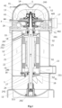
FIG. 1 shows a cross-sectional view of a centrifugal compressor; and -
FIG. 2 shows an exploded view of a centrifugal compressor. - It can be easily understood that according to the technical solutions of the present disclosure, those skilled in the art can propose a variety of mutually replaceable structural modes and implementations. Therefore, the following specific embodiments and the accompanying drawings are merely exemplary illustrations of the technical solutions of the present disclosure, and should not be regarded as the entirety of the present disclosure or as definitions or limitations to the technical solutions of the present disclosure.
- The orientational terms that have been mentioned or might be mentioned in this specification, such as "upper", "lower", "left", "right", "front", "rear", "front side", "back side", "top", "bottom", etc., are defined relative to the configurations shown in the drawings. They are relative concepts, so they may change accordingly according to their different locations and different states of use. Therefore, these or other orientational terms should not be interpreted as restrictive terms.
- Referring to
FIGS. 1 and2 , a centrifugal compressor is shown, which includes: ashell 1, which has afluid inlet 15 at a first position of the shell, and afluid outlet 17 at a second position of the shell, which is higher than the first position; amotor assembly 2, which is arranged in theshell 1 and includes a stator and a rotor, wherein the rotor includes a vertically arrangedrotor shaft 24, and therotor shaft 24 includes alower end 242 and anupper end 243; a centrifugal compression mechanism 4, an impeller of which is connected with the rotor shaft (such as its upper end 243) so as to be driven by themotor assembly 2; and a guide member 3, which is located above the centrifugal compression mechanism and defines aflow passage 5 alone or together with atop part 13 of theshell 1; wherein when the centrifugal compressor is working, a fluid from thefluid inlet 15 passes through themotor assembly 2 and then flows from an outer periphery of the centrifugal compression mechanism 4 into theflow passage 5 from bottom to top, is diverted in theflow passage 5, thereby enters the centrifugal compression mechanism 4 from top to bottom, and exits from thefluid outlet 17 after being compressed and pressurized by the centrifugal compression mechanism 4, substantially as indicated by the hollow arrows. - In the centrifugal compressor according to the embodiments of the claimed invention, the fluid first passes through the
motor assembly 2 and cools themotor assembly 2, including passing through a gap G1 between the rotor and the stator and an outer side of amotor housing 21; then, the fluid flows from a passage located radially outwardly of the centrifugal compression mechanism 4 to theflow passage 5 defined between the guide member 3 and thetop part 13 of the shell, is diverted and enters the centrifugal compression mechanism 4 from top to bottom to be compressed and pressurized; for example, the fluid after a two-stage compression and pressurization is finally discharged from thefluid outlet 17. A feature of the centrifugal compressor according to the embodiments of the claimed invention is the use of intake air to cool the motor assembly; that is, for example, an intake air flow from an evaporator is directly guided to themotor assembly 2 to cool themotor assembly 2. Since the fluid according to the embodiments of the claimed invention passes through the centrifugal compression mechanism 4 from top to bottom, when the centrifugal compression mechanism 4 is working, the impeller thereof will exert an upward force on therotor shaft 24, which counteracts the gravity of therotor shaft 24 itself, thereby reducing axial stress ofbearings rotor shaft 24. In addition, the device according to this embodiment provides a centrifugal compressor with a compact design so as to be applied to low-power operating conditions. - In the embodiment according to the claimed invention, the
rotor shaft 24 is supported by a first bearing 31 at a lower part and a second bearing 32 at an upper part. The first bearing 31 is disposed in afirst bearing seat 27 at the bottom of themotor assembly 2, and the second bearing 32 is disposed in a second bearingbracket 26 at the top of the motor assembly. Theshell 1 substantially includes abottom part 11, amiddle part 12 and atop part 13. Thefluid inlet 15 may be formed as a pipe, which may extend in a radial direction and be flush with the bottom of themotor housing 21. In some embodiments, thefluid inlet 15 may, for example, extend to the interior of theshell 1 and be aligned with anopening 211 at the bottom of themotor housing 21. There may be a gap G2 between thefluid inlet 15 and theopening 211, so that the airflow from thefluid inlet 15 partially flows from the gap G1 between the motor stator and the rotor, and partially passes through the outside of themotor assembly 2. The top of themotor housing 21 may also have anopening 212 to allow the airflow passing through the gap G1 to exit, and anoil guide pipe 251 may extend out of theopening 212. Thebottom part 11 of theshell 1 has an oil tank. Lubrication oil for the first bearing 31, the second bearing 32 and other optional members may be contained in the oil tank. Thelower end 242 of therotor shaft 24 is located in the oil tank; specifically, it may be inserted into a limitingmember 111 in the oil tank. Therotor shaft 24 defines anaxial oil passage 241 therein. For example, as shown inFIG. 1 , the rotor shaft may be formed as a hollow member with anoil passage 241 therein. Theoil passage 241 may be straight (in the axial direction of the rotor shaft 242) or oblique. Therotor shaft 24 hasradial perforations rotor shaft 24 will generate negative pressure in theoil passage 241, so that the oil in the oil tank is drawn through theoil passage 241 in the direction of the arrows, and the oil will flow radially out of theperforations oil cup 25 is arranged below the second bearing 32. The oil that has passed through and lubricated the second bearing 32 falls into theoil cup 25, is guided to an inner side of a side wall of the shell through the obliquely arrangedoil guide pipe 251, and returns to the oil tank along the inner side of the side wall of the shell. The arrangement of theoil cup 25 and theoil guide pipe 251 prevents the lubrication oil from entering the interior of themotor assembly 2. In some embodiments, a diameter of theperforation 246 corresponding to the first bearing 31 may be smaller than a diameter of theperforation 247 corresponding to the second bearing 32 to prevent the oil from flowing out of theperforation 246 too much to reach theperforation 247. - With reference to
FIGS. 1 and2 , in the illustrated embodiment, themotor assembly 2 may include: amotor housing 21; astator 22 fixed on an inner side of themotor housing 21; and a rotor located radially inwardly of the stator. In some embodiments, the rotor may include arotor shaft 24 and apermanent magnet 23, and thestator 22 may have a winding. When thestator 22 is energized, the rotor is capable of rotating relative to thestator 22. Themotor assembly 2 may further include: afirst bearing seat 27 at a bottom of themotor housing 21 and afirst bearing 31 therein; anoil cup 25 at a top of themotor housing 21; and asecond bearing bracket 26 located above theoil cup 25 and asecond bearing 32 therein. In an alternative embodiment, themotor assembly 2 may have other suitable structures and components. In the illustrated embodiment, the bottom of themotor housing 21 is connected to theshell 1 throughseveral support brackets 16. For example, the bottom of themotor housing 21 is connected to the inner side of the side wall of theshell 1. The top of themotor housing 21 is connected to thesecond bearing bracket 26, and thesecond bearing bracket 26 is mounted on theshell 1, such as being directly supported on themiddle part 12 of theshell 1 or connected to the inner wall of theshell 1. - The centrifugal compression mechanism 4 is arranged on the
second bearing bracket 26. For example, in some embodiments, avolute 43 of the centrifugal compression mechanism may be directly arranged on thesecond bearing bracket 26, and outer peripheries of thesecond bearing bracket 26 and thevolute 43 includefluid passages fluid passages second bearing bracket 26 and thevolute 43 at corresponding positions. Although shown in the drawings, the centrifugal compression mechanism 4 includes two stages consisting of a first-stage impeller 41 and a second-stage impeller 44. In an alternative embodiment, the centrifugal compression mechanism 4 may only include one stage or more than two stages. In the illustrated embodiment, the centrifugal compression mechanism 4 includes the first-stage impeller 41, apartition 42, thevolute 43, and the second-stage impeller 44, through which therotor shaft 24 passes. The first-stage impeller 41 and the second-stage impeller 44 are connected to therotor shaft 24 and rotate with the rotor shaft, whereas thepartition 42 and thevolute 43 are relatively fixed. Afirst sleeve 52 is arranged between the first-stage impeller 41 and the second-stage impeller 44, and asecond sleeve 33 is arranged between the second-stage impeller 44 and thesecond bearing 32. In the illustrated embodiment, anoutlet 443 of thevolute 43 is in communication with thefluid outlet 17 of the shell. The fluid entering the centrifugal compression mechanism through theflow passage 5 is compressed by the first-stage impeller 41 and then passes between an upper surface of thevolute 43 and thepartition 42. Then, the fluid is compressed by the second-stage impeller 44, and exits from thefluid outlet 17 through theoutlet 443 of the volute so as to be supplied to devices downstream of the compressor. - As shown in
FIG. 2 , a guide member 3 is arranged above the centrifugal compression mechanism 4, and the guide member 3 may be directly supported by thevolute 43, for example. In the illustrated embodiment, the guide member 3 and thetop part 13 of theshell 1 together define theflow passage 5 that guides the fluid to detour or divert, thereby passing through the centrifugal compression mechanism 4 from top to bottom. In an alternative embodiment, the guide member 3 may define theflow passage 5 by itself. For example, the guide member 3 may be formed to have theflow passage 5, or the guide member 3 is assembled by a plurality of members to define theflow passage 5 together. In some embodiments, the guide member 3 has a hemispherical shape, and the inner side of thetop part 13 of the shell may also be dome-shaped. In addition, in order to guide the fluid, an angle at which the airflow enters the impeller is adjusted to reduce the loss of airflow. In some embodiments, thetop part 13 of the shell has aninward protrusion 14. In an alternative embodiment, the guide member 3 and thetop part 13 of the shell may have any other suitable shapes. - In another aspect, a refrigerating device is provided, which includes the centrifugal compressor according to various embodiments.
- The specific exemplary embodiments described above are merely for describing the present invention more clearly, and various components are clearly illustrated or depicted to make it easier to understand the present invention. Those skilled in the art can readily make various modifications or changes to the present exemplary embodiments without departing from the scope of the claims. Therefore, it should be understood that these modifications or changes should be included within the scope of protection of the present invention as defined by the claims.
Claims (9)
- A centrifugal compressor, comprising:a shell (1), which has a fluid inlet (15) at a first position of the shell (1), and a fluid outlet (17) at a second position of the shell (1), which is higher than the first position;a motor assembly (2), which is arranged in the shell (1) and comprises a stator (22) and a rotor, the rotor comprising a vertically arranged rotor shaft (24), and the rotor shaft (24) comprising a lower end (242) and an upper end (243);a centrifugal compression mechanism (4), an impeller of which is connected with the rotor shaft (24) so as to be driven by the motor assembly (2); anda guide member (3), which is located above the centrifugal compression mechanism (4), and which defines a flow passage (5) alone or together with a top part of the shell (1);wherein the centrifugal compressor is configured such that when the centrifugal compressor is working, a fluid from the fluid inlet (15) passes through the motor assembly (2) and then flows from an outer periphery of the centrifugal compression mechanism (4) into the flow passage (5) from bottom to top, is diverted in the flow passage (5), thereby enters the centrifugal compression mechanism (4) from top to bottom, and exits from the fluid outlet (17),wherein the rotor shaft (24) is supported by a first bearing (31) at a lower part and a second bearing (32) at an upper part, characterized in that a bottom part of the shell (1) has an oil tank,and the lower end (242) of the rotor shaft (24) is located in the oil tank; and in that the rotor shaft (24) defines an axial or oblique oil passage (241) therein, and has radial perforations (246, 247) at positions corresponding to the first bearing (31) and the second bearing (32).
- The centrifugal compressor according to claim 1, wherein the motor assembly (2) comprises:a motor housing (21), the stator (22) fixed on an inner side of the motor housing (21) and the rotor located radially inwardly of the stator (22), the rotor being capable of rotating relative to the stator (22) when energized;a first bearing seat (27) at a bottom of the motor housing (21) and the first bearing (31) therein;an oil cup (25) at a top of the motor housing (21); anda second bearing bracket (26) located above the oil cup (25) and the second bearing (32) therein.
- The centrifugal compressor according to claim 2, wherein the bottom of the motor housing (21) is connected to the shell (1) through a support bracket (16), the top of the motor housing (21) is connected to the second bearing bracket (26), and the second bearing bracket (26) is supported by the shell (1); and wherein the oil cup (25) comprises an oil guide pipe (251) that is arranged obliquely to guide oil in the oil cup (25) to an inner wall of the shell (1) so that the oil is returned to the oil tank at the bottom part of the shell (1).
- The centrifugal compressor according to claim 2 or 3, wherein an outer periphery of the second bearing bracket (26) has a fluid passage (71) that allows fluid to pass through from bottom to top.
- The centrifugal compressor according to claim 2, 3 or 4, wherein the centrifugal compression mechanism (4) comprises one or more compression stages.
- The centrifugal compressor according to claim 5, wherein the centrifugal compression mechanism (4) comprises a first-stage impeller (41), a partition (42), a volute (43), and a second-stage impeller (44), and wherein an outlet (443) of the volute (43) communicates with the fluid outlet (17) of the shell (1), wherein the centrifugal compressor is configured such that the fluid passes between an upper surface of the volute (43) and the partition (42) after being compressed by the first-stage impeller (41) and is then compressed by the second-stage impeller (44), and then exits from the fluid outlet (17) via the outlet (443) of the volute (43).
- The centrifugal compressor according to claim 6, wherein outer peripheries of the volute (43) and the second bearing bracket (26) have corresponding fluid passages (442, 71) to allow fluid to pass through from bottom to top.
- The centrifugal compressor according to any preceding claim, wherein the guide member (3) is hemispherical, and the top part of the shell (1) has an inward protrusion.
- A refrigerating device, comprising the centrifugal compressor according to any one of claims 1 to 8.
Applications Claiming Priority (2)
| Application Number | Priority Date | Filing Date | Title |
|---|---|---|---|
| CN201910863359.4A CN112483429B (en) | 2019-09-12 | 2019-09-12 | Centrifugal compressors and refrigeration units |
| PCT/US2020/050098 WO2021050662A1 (en) | 2019-09-12 | 2020-09-10 | Centrifugal compressor and refrigerating device |
Publications (2)
| Publication Number | Publication Date |
|---|---|
| EP4028665A1 EP4028665A1 (en) | 2022-07-20 |
| EP4028665B1 true EP4028665B1 (en) | 2024-08-28 |
Family
ID=72659875
Family Applications (1)
| Application Number | Title | Priority Date | Filing Date |
|---|---|---|---|
| EP20781144.9A Active EP4028665B1 (en) | 2019-09-12 | 2020-09-10 | Centrifugal compressor and refrigerating device |
Country Status (4)
| Country | Link |
|---|---|
| US (1) | US11506210B2 (en) |
| EP (1) | EP4028665B1 (en) |
| CN (1) | CN112483429B (en) |
| WO (1) | WO2021050662A1 (en) |
Families Citing this family (2)
| Publication number | Priority date | Publication date | Assignee | Title |
|---|---|---|---|---|
| US12038018B2 (en) * | 2020-03-02 | 2024-07-16 | Cap Co., Ltd. | Blower |
| US20250327457A1 (en) * | 2024-04-19 | 2025-10-23 | Garrett Transportation I Inc. | Multi stage compressor |
Family Cites Families (24)
| Publication number | Priority date | Publication date | Assignee | Title |
|---|---|---|---|---|
| JPS60187789A (en) | 1984-03-05 | 1985-09-25 | Mitsubishi Electric Corp | Scroll compressor |
| MY126636A (en) | 1994-10-24 | 2006-10-31 | Hitachi Ltd | Scroll compressor |
| US5533875A (en) * | 1995-04-07 | 1996-07-09 | American Standard Inc. | Scroll compressor having a frame and open sleeve for controlling gas and lubricant flow |
| JP3924834B2 (en) | 1997-03-19 | 2007-06-06 | 株式会社日立製作所 | Positive displacement fluid machinery |
| US6000917A (en) | 1997-11-06 | 1999-12-14 | American Standard Inc. | Control of suction gas and lubricant flow in a scroll compressor |
| JPH11294879A (en) * | 1998-02-16 | 1999-10-29 | Daikin Ind Ltd | Refrigerating system |
| US6098753A (en) | 1998-06-05 | 2000-08-08 | Pratt & Whitney Canada Corp. | System for delivering pressurized lubricant fluids to an interior of a rotating hollow shaft |
| US6146118A (en) | 1998-06-22 | 2000-11-14 | Tecumseh Products Company | Oldham coupling for a scroll compressor |
| US6685447B2 (en) * | 2002-01-25 | 2004-02-03 | Hamilton Sundstrand | Liquid cooled integrated rotordynamic motor/generator station with sealed power electronic controls |
| JP3731068B2 (en) | 2002-06-05 | 2006-01-05 | ダイキン工業株式会社 | Rotary compressor |
| TWI344512B (en) | 2004-02-27 | 2011-07-01 | Sanyo Electric Co | Two-stage rotary compressor |
| JP4433184B2 (en) * | 2004-11-05 | 2010-03-17 | 株式会社富士通ゼネラル | Compressor |
| DE602006020880D1 (en) | 2005-06-29 | 2011-05-05 | Panasonic Corp | FLOW MACHINE AND COOLING CYCLE DEVICE |
| TWI315382B (en) * | 2006-12-26 | 2009-10-01 | Ind Tech Res Inst | The rotor mechanism of the centrifugal compressor |
| US8133043B2 (en) | 2008-10-14 | 2012-03-13 | Bitzer Scroll, Inc. | Suction duct and scroll compressor incorporating same |
| US9217434B2 (en) | 2011-04-15 | 2015-12-22 | Emerson Climate Technologies, Inc. | Compressor having drive shaft with fluid passages |
| CN202100491U (en) * | 2011-04-22 | 2012-01-04 | 爱科腾博(大连)科技有限公司 | Turbo compressor |
| GB201122142D0 (en) * | 2011-12-21 | 2012-02-01 | Venus Systems Ltd | Centrifugal compressors |
| JP5933042B2 (en) | 2013-01-16 | 2016-06-08 | 三菱電機株式会社 | Hermetic compressor and vapor compression refrigeration cycle apparatus including the hermetic compressor |
| WO2015125304A1 (en) | 2014-02-24 | 2015-08-27 | 三菱電機株式会社 | Compressor |
| JP6302813B2 (en) * | 2014-09-30 | 2018-03-28 | 日立ジョンソンコントロールズ空調株式会社 | Scroll compressor and refrigeration cycle apparatus using the same |
| CN106567833B (en) | 2015-10-13 | 2019-01-29 | 艾默生环境优化技术(苏州)有限公司 | Rotary compressor and method for improving lubricating effect thereof |
| CN106015032B (en) * | 2016-06-28 | 2018-05-22 | 杭州万辰机电科技有限公司 | Centrifugal compressor |
| US11274679B2 (en) * | 2017-02-14 | 2022-03-15 | Danfoss A/S | Oil free centrifugal compressor for use in low capacity applications |
-
2019
- 2019-09-12 CN CN201910863359.4A patent/CN112483429B/en active Active
-
2020
- 2020-09-10 EP EP20781144.9A patent/EP4028665B1/en active Active
- 2020-09-10 WO PCT/US2020/050098 patent/WO2021050662A1/en not_active Ceased
- 2020-09-10 US US15/734,854 patent/US11506210B2/en active Active
Also Published As
| Publication number | Publication date |
|---|---|
| CN112483429A (en) | 2021-03-12 |
| EP4028665A1 (en) | 2022-07-20 |
| WO2021050662A1 (en) | 2021-03-18 |
| US20210364001A1 (en) | 2021-11-25 |
| CN112483429B (en) | 2025-08-26 |
| US11506210B2 (en) | 2022-11-22 |
Similar Documents
| Publication | Publication Date | Title |
|---|---|---|
| EP4028666B1 (en) | Centrifugal compressor with motor cooling by compressed process gas and bearing lubricant flow through a hollow shaft | |
| JP5692177B2 (en) | Compressor | |
| NL1018212C2 (en) | Compressor unit comprising a centrifugal compressor and an electric motor. | |
| US9651047B2 (en) | Compressor having a partitioned discharge chamber | |
| JP6213500B2 (en) | Electric turbo compressor | |
| US20020067998A1 (en) | Compressor utilizing shell with low pressure side motor and high pressure side oil sump | |
| US11781548B2 (en) | Oil separation apparatus and horizontal compressor | |
| US11506210B2 (en) | Centrifugal compressor and refrigerating device | |
| JPH076517B2 (en) | Rotor reverse rotation prevention device in screw compressor | |
| CN119755126A (en) | Multistage centrifugal pump axial force balance mechanism and multistage centrifugal pump | |
| JP6597744B2 (en) | Oil separator | |
| US20200217320A1 (en) | Cylindrical symmetric volumetric machine | |
| KR960001625B1 (en) | Shroul Compressor | |
| JP3870612B2 (en) | Damping bearing and multistage centrifugal compressor using the same | |
| JP6501883B2 (en) | Scroll compressor | |
| CN109083841A (en) | It is provided with the screw compressor of fluid deflector and part flow arrangement | |
| WO2019064883A1 (en) | Oil separator | |
| CN109386467B (en) | Oil separation device and horizontal compressor | |
| US20170074267A1 (en) | A scroll compressor | |
| CN110714801B (en) | Expander and fluid circulation system comprising an expander | |
| JP4283063B2 (en) | Horizontal scroll air compressor | |
| JP2024132383A (en) | Compressor | |
| JP2621037B2 (en) | Scroll compressor | |
| JPH08159080A (en) | Canned motor pump | |
| JP2005344696A (en) | Motor pump |
Legal Events
| Date | Code | Title | Description |
|---|---|---|---|
| STAA | Information on the status of an ep patent application or granted ep patent |
Free format text: STATUS: UNKNOWN |
|
| STAA | Information on the status of an ep patent application or granted ep patent |
Free format text: STATUS: THE INTERNATIONAL PUBLICATION HAS BEEN MADE |
|
| PUAI | Public reference made under article 153(3) epc to a published international application that has entered the european phase |
Free format text: ORIGINAL CODE: 0009012 |
|
| STAA | Information on the status of an ep patent application or granted ep patent |
Free format text: STATUS: REQUEST FOR EXAMINATION WAS MADE |
|
| 17P | Request for examination filed |
Effective date: 20210110 |
|
| AK | Designated contracting states |
Kind code of ref document: A1 Designated state(s): AL AT BE BG CH CY CZ DE DK EE ES FI FR GB GR HR HU IE IS IT LI LT LU LV MC MK MT NL NO PL PT RO RS SE SI SK SM TR |
|
| DAV | Request for validation of the european patent (deleted) | ||
| DAX | Request for extension of the european patent (deleted) | ||
| GRAP | Despatch of communication of intention to grant a patent |
Free format text: ORIGINAL CODE: EPIDOSNIGR1 |
|
| STAA | Information on the status of an ep patent application or granted ep patent |
Free format text: STATUS: GRANT OF PATENT IS INTENDED |
|
| INTG | Intention to grant announced |
Effective date: 20240327 |
|
| GRAS | Grant fee paid |
Free format text: ORIGINAL CODE: EPIDOSNIGR3 |
|
| GRAA | (expected) grant |
Free format text: ORIGINAL CODE: 0009210 |
|
| STAA | Information on the status of an ep patent application or granted ep patent |
Free format text: STATUS: THE PATENT HAS BEEN GRANTED |
|
| AK | Designated contracting states |
Kind code of ref document: B1 Designated state(s): AL AT BE BG CH CY CZ DE DK EE ES FI FR GB GR HR HU IE IS IT LI LT LU LV MC MK MT NL NO PL PT RO RS SE SI SK SM TR |
|
| REG | Reference to a national code |
Ref country code: CH Ref legal event code: EP |
|
| REG | Reference to a national code |
Ref country code: DE Ref legal event code: R096 Ref document number: 602020036733 Country of ref document: DE |
|
| REG | Reference to a national code |
Ref country code: IE Ref legal event code: FG4D |
|
| REG | Reference to a national code |
Ref country code: LT Ref legal event code: MG9D |
|
| PG25 | Lapsed in a contracting state [announced via postgrant information from national office to epo] |
Ref country code: NO Free format text: LAPSE BECAUSE OF FAILURE TO SUBMIT A TRANSLATION OF THE DESCRIPTION OR TO PAY THE FEE WITHIN THE PRESCRIBED TIME-LIMIT Effective date: 20241128 |
|
| REG | Reference to a national code |
Ref country code: AT Ref legal event code: MK05 Ref document number: 1718211 Country of ref document: AT Kind code of ref document: T Effective date: 20240828 |
|
| PG25 | Lapsed in a contracting state [announced via postgrant information from national office to epo] |
Ref country code: NL Free format text: LAPSE BECAUSE OF FAILURE TO SUBMIT A TRANSLATION OF THE DESCRIPTION OR TO PAY THE FEE WITHIN THE PRESCRIBED TIME-LIMIT Effective date: 20240828 Ref country code: PT Free format text: LAPSE BECAUSE OF FAILURE TO SUBMIT A TRANSLATION OF THE DESCRIPTION OR TO PAY THE FEE WITHIN THE PRESCRIBED TIME-LIMIT Effective date: 20241230 Ref country code: PL Free format text: LAPSE BECAUSE OF FAILURE TO SUBMIT A TRANSLATION OF THE DESCRIPTION OR TO PAY THE FEE WITHIN THE PRESCRIBED TIME-LIMIT Effective date: 20240828 Ref country code: GR Free format text: LAPSE BECAUSE OF FAILURE TO SUBMIT A TRANSLATION OF THE DESCRIPTION OR TO PAY THE FEE WITHIN THE PRESCRIBED TIME-LIMIT Effective date: 20241129 Ref country code: FI Free format text: LAPSE BECAUSE OF FAILURE TO SUBMIT A TRANSLATION OF THE DESCRIPTION OR TO PAY THE FEE WITHIN THE PRESCRIBED TIME-LIMIT Effective date: 20240828 |
|
| PG25 | Lapsed in a contracting state [announced via postgrant information from national office to epo] |
Ref country code: BG Free format text: LAPSE BECAUSE OF FAILURE TO SUBMIT A TRANSLATION OF THE DESCRIPTION OR TO PAY THE FEE WITHIN THE PRESCRIBED TIME-LIMIT Effective date: 20240828 |
|
| PG25 | Lapsed in a contracting state [announced via postgrant information from national office to epo] |
Ref country code: LV Free format text: LAPSE BECAUSE OF FAILURE TO SUBMIT A TRANSLATION OF THE DESCRIPTION OR TO PAY THE FEE WITHIN THE PRESCRIBED TIME-LIMIT Effective date: 20240828 |
|
| REG | Reference to a national code |
Ref country code: NL Ref legal event code: MP Effective date: 20240828 |
|
| PG25 | Lapsed in a contracting state [announced via postgrant information from national office to epo] |
Ref country code: AT Free format text: LAPSE BECAUSE OF FAILURE TO SUBMIT A TRANSLATION OF THE DESCRIPTION OR TO PAY THE FEE WITHIN THE PRESCRIBED TIME-LIMIT Effective date: 20240828 Ref country code: IS Free format text: LAPSE BECAUSE OF FAILURE TO SUBMIT A TRANSLATION OF THE DESCRIPTION OR TO PAY THE FEE WITHIN THE PRESCRIBED TIME-LIMIT Effective date: 20241228 |
|
| PG25 | Lapsed in a contracting state [announced via postgrant information from national office to epo] |
Ref country code: HR Free format text: LAPSE BECAUSE OF FAILURE TO SUBMIT A TRANSLATION OF THE DESCRIPTION OR TO PAY THE FEE WITHIN THE PRESCRIBED TIME-LIMIT Effective date: 20240828 |
|
| PG25 | Lapsed in a contracting state [announced via postgrant information from national office to epo] |
Ref country code: RS Free format text: LAPSE BECAUSE OF FAILURE TO SUBMIT A TRANSLATION OF THE DESCRIPTION OR TO PAY THE FEE WITHIN THE PRESCRIBED TIME-LIMIT Effective date: 20241128 Ref country code: ES Free format text: LAPSE BECAUSE OF FAILURE TO SUBMIT A TRANSLATION OF THE DESCRIPTION OR TO PAY THE FEE WITHIN THE PRESCRIBED TIME-LIMIT Effective date: 20240828 |
|
| PG25 | Lapsed in a contracting state [announced via postgrant information from national office to epo] |
Ref country code: RS Free format text: LAPSE BECAUSE OF FAILURE TO SUBMIT A TRANSLATION OF THE DESCRIPTION OR TO PAY THE FEE WITHIN THE PRESCRIBED TIME-LIMIT Effective date: 20241128 Ref country code: PT Free format text: LAPSE BECAUSE OF FAILURE TO SUBMIT A TRANSLATION OF THE DESCRIPTION OR TO PAY THE FEE WITHIN THE PRESCRIBED TIME-LIMIT Effective date: 20241230 Ref country code: PL Free format text: LAPSE BECAUSE OF FAILURE TO SUBMIT A TRANSLATION OF THE DESCRIPTION OR TO PAY THE FEE WITHIN THE PRESCRIBED TIME-LIMIT Effective date: 20240828 Ref country code: NO Free format text: LAPSE BECAUSE OF FAILURE TO SUBMIT A TRANSLATION OF THE DESCRIPTION OR TO PAY THE FEE WITHIN THE PRESCRIBED TIME-LIMIT Effective date: 20241128 Ref country code: NL Free format text: LAPSE BECAUSE OF FAILURE TO SUBMIT A TRANSLATION OF THE DESCRIPTION OR TO PAY THE FEE WITHIN THE PRESCRIBED TIME-LIMIT Effective date: 20240828 Ref country code: LV Free format text: LAPSE BECAUSE OF FAILURE TO SUBMIT A TRANSLATION OF THE DESCRIPTION OR TO PAY THE FEE WITHIN THE PRESCRIBED TIME-LIMIT Effective date: 20240828 Ref country code: IS Free format text: LAPSE BECAUSE OF FAILURE TO SUBMIT A TRANSLATION OF THE DESCRIPTION OR TO PAY THE FEE WITHIN THE PRESCRIBED TIME-LIMIT Effective date: 20241228 Ref country code: HR Free format text: LAPSE BECAUSE OF FAILURE TO SUBMIT A TRANSLATION OF THE DESCRIPTION OR TO PAY THE FEE WITHIN THE PRESCRIBED TIME-LIMIT Effective date: 20240828 Ref country code: GR Free format text: LAPSE BECAUSE OF FAILURE TO SUBMIT A TRANSLATION OF THE DESCRIPTION OR TO PAY THE FEE WITHIN THE PRESCRIBED TIME-LIMIT Effective date: 20241129 Ref country code: FI Free format text: LAPSE BECAUSE OF FAILURE TO SUBMIT A TRANSLATION OF THE DESCRIPTION OR TO PAY THE FEE WITHIN THE PRESCRIBED TIME-LIMIT Effective date: 20240828 Ref country code: ES Free format text: LAPSE BECAUSE OF FAILURE TO SUBMIT A TRANSLATION OF THE DESCRIPTION OR TO PAY THE FEE WITHIN THE PRESCRIBED TIME-LIMIT Effective date: 20240828 Ref country code: BG Free format text: LAPSE BECAUSE OF FAILURE TO SUBMIT A TRANSLATION OF THE DESCRIPTION OR TO PAY THE FEE WITHIN THE PRESCRIBED TIME-LIMIT Effective date: 20240828 Ref country code: AT Free format text: LAPSE BECAUSE OF FAILURE TO SUBMIT A TRANSLATION OF THE DESCRIPTION OR TO PAY THE FEE WITHIN THE PRESCRIBED TIME-LIMIT Effective date: 20240828 |
|
| PG25 | Lapsed in a contracting state [announced via postgrant information from national office to epo] |
Ref country code: DK Free format text: LAPSE BECAUSE OF FAILURE TO SUBMIT A TRANSLATION OF THE DESCRIPTION OR TO PAY THE FEE WITHIN THE PRESCRIBED TIME-LIMIT Effective date: 20240828 Ref country code: SM Free format text: LAPSE BECAUSE OF FAILURE TO SUBMIT A TRANSLATION OF THE DESCRIPTION OR TO PAY THE FEE WITHIN THE PRESCRIBED TIME-LIMIT Effective date: 20240828 Ref country code: RO Free format text: LAPSE BECAUSE OF FAILURE TO SUBMIT A TRANSLATION OF THE DESCRIPTION OR TO PAY THE FEE WITHIN THE PRESCRIBED TIME-LIMIT Effective date: 20240828 |
|
| PG25 | Lapsed in a contracting state [announced via postgrant information from national office to epo] |
Ref country code: EE Free format text: LAPSE BECAUSE OF FAILURE TO SUBMIT A TRANSLATION OF THE DESCRIPTION OR TO PAY THE FEE WITHIN THE PRESCRIBED TIME-LIMIT Effective date: 20240828 |
|
| PG25 | Lapsed in a contracting state [announced via postgrant information from national office to epo] |
Ref country code: CZ Free format text: LAPSE BECAUSE OF FAILURE TO SUBMIT A TRANSLATION OF THE DESCRIPTION OR TO PAY THE FEE WITHIN THE PRESCRIBED TIME-LIMIT Effective date: 20240828 |
|
| PG25 | Lapsed in a contracting state [announced via postgrant information from national office to epo] |
Ref country code: SK Free format text: LAPSE BECAUSE OF FAILURE TO SUBMIT A TRANSLATION OF THE DESCRIPTION OR TO PAY THE FEE WITHIN THE PRESCRIBED TIME-LIMIT Effective date: 20240828 Ref country code: IT Free format text: LAPSE BECAUSE OF FAILURE TO SUBMIT A TRANSLATION OF THE DESCRIPTION OR TO PAY THE FEE WITHIN THE PRESCRIBED TIME-LIMIT Effective date: 20240828 |
|
| REG | Reference to a national code |
Ref country code: CH Ref legal event code: PL |
|
| PG25 | Lapsed in a contracting state [announced via postgrant information from national office to epo] |
Ref country code: LU Free format text: LAPSE BECAUSE OF NON-PAYMENT OF DUE FEES Effective date: 20240910 |
|
| REG | Reference to a national code |
Ref country code: DE Ref legal event code: R097 Ref document number: 602020036733 Country of ref document: DE |
|
| PLBE | No opposition filed within time limit |
Free format text: ORIGINAL CODE: 0009261 |
|
| STAA | Information on the status of an ep patent application or granted ep patent |
Free format text: STATUS: NO OPPOSITION FILED WITHIN TIME LIMIT |
|
| PG25 | Lapsed in a contracting state [announced via postgrant information from national office to epo] |
Ref country code: MC Free format text: LAPSE BECAUSE OF FAILURE TO SUBMIT A TRANSLATION OF THE DESCRIPTION OR TO PAY THE FEE WITHIN THE PRESCRIBED TIME-LIMIT Effective date: 20240828 |
|
| REG | Reference to a national code |
Ref country code: BE Ref legal event code: MM Effective date: 20240930 |
|
| PG25 | Lapsed in a contracting state [announced via postgrant information from national office to epo] |
Ref country code: BE Free format text: LAPSE BECAUSE OF NON-PAYMENT OF DUE FEES Effective date: 20240930 |
|
| GBPC | Gb: european patent ceased through non-payment of renewal fee |
Effective date: 20241128 |
|
| PG25 | Lapsed in a contracting state [announced via postgrant information from national office to epo] |
Ref country code: CH Free format text: LAPSE BECAUSE OF NON-PAYMENT OF DUE FEES Effective date: 20240930 |
|
| PG25 | Lapsed in a contracting state [announced via postgrant information from national office to epo] |
Ref country code: IE Free format text: LAPSE BECAUSE OF NON-PAYMENT OF DUE FEES Effective date: 20240910 |
|
| 26N | No opposition filed |
Effective date: 20250530 |
|
| PG25 | Lapsed in a contracting state [announced via postgrant information from national office to epo] |
Ref country code: SE Free format text: LAPSE BECAUSE OF FAILURE TO SUBMIT A TRANSLATION OF THE DESCRIPTION OR TO PAY THE FEE WITHIN THE PRESCRIBED TIME-LIMIT Effective date: 20240828 |
|
| PGFP | Annual fee paid to national office [announced via postgrant information from national office to epo] |
Ref country code: DE Payment date: 20250820 Year of fee payment: 6 |
|
| PG25 | Lapsed in a contracting state [announced via postgrant information from national office to epo] |
Ref country code: GB Free format text: LAPSE BECAUSE OF NON-PAYMENT OF DUE FEES Effective date: 20241128 |
|
| PGFP | Annual fee paid to national office [announced via postgrant information from national office to epo] |
Ref country code: FR Payment date: 20250821 Year of fee payment: 6 |
|
| PG25 | Lapsed in a contracting state [announced via postgrant information from national office to epo] |
Ref country code: CY Free format text: LAPSE BECAUSE OF FAILURE TO SUBMIT A TRANSLATION OF THE DESCRIPTION OR TO PAY THE FEE WITHIN THE PRESCRIBED TIME-LIMIT; INVALID AB INITIO Effective date: 20200910 |
|
| PG25 | Lapsed in a contracting state [announced via postgrant information from national office to epo] |
Ref country code: HU Free format text: LAPSE BECAUSE OF FAILURE TO SUBMIT A TRANSLATION OF THE DESCRIPTION OR TO PAY THE FEE WITHIN THE PRESCRIBED TIME-LIMIT; INVALID AB INITIO Effective date: 20200910 |
|
| PG25 | Lapsed in a contracting state [announced via postgrant information from national office to epo] |
Ref country code: TR Free format text: LAPSE BECAUSE OF FAILURE TO SUBMIT A TRANSLATION OF THE DESCRIPTION OR TO PAY THE FEE WITHIN THE PRESCRIBED TIME-LIMIT Effective date: 20240828 |
|
| PG25 | Lapsed in a contracting state [announced via postgrant information from national office to epo] |
Ref country code: SI Free format text: LAPSE BECAUSE OF FAILURE TO SUBMIT A TRANSLATION OF THE DESCRIPTION OR TO PAY THE FEE WITHIN THE PRESCRIBED TIME-LIMIT Effective date: 20240828 |
|
| PG25 | Lapsed in a contracting state [announced via postgrant information from national office to epo] |
Ref country code: LT Free format text: LAPSE BECAUSE OF FAILURE TO SUBMIT A TRANSLATION OF THE DESCRIPTION OR TO PAY THE FEE WITHIN THE PRESCRIBED TIME-LIMIT Effective date: 20240828 |