EP4028629B1 - Unterwasserunterstützende verrohrungshubwinde - Google Patents
Unterwasserunterstützende verrohrungshubwinde Download PDFInfo
- Publication number
- EP4028629B1 EP4028629B1 EP20879243.2A EP20879243A EP4028629B1 EP 4028629 B1 EP4028629 B1 EP 4028629B1 EP 20879243 A EP20879243 A EP 20879243A EP 4028629 B1 EP4028629 B1 EP 4028629B1
- Authority
- EP
- European Patent Office
- Prior art keywords
- jack
- subsea
- assist
- slip bowl
- snubbing
- Prior art date
- Legal status (The legal status is an assumption and is not a legal conclusion. Google has not performed a legal analysis and makes no representation as to the accuracy of the status listed.)
- Active
Links
Images
Classifications
-
- E—FIXED CONSTRUCTIONS
- E21—EARTH OR ROCK DRILLING; MINING
- E21B—EARTH OR ROCK DRILLING; OBTAINING OIL, GAS, WATER, SOLUBLE OR MELTABLE MATERIALS OR A SLURRY OF MINERALS FROM WELLS
- E21B19/00—Handling rods, casings, tubes or the like outside the borehole, e.g. in the derrick; Apparatus for feeding the rods or cables
- E21B19/08—Apparatus for feeding the rods or cables; Apparatus for increasing or decreasing the pressure on the drilling tool; Apparatus for counterbalancing the weight of the rods
-
- E—FIXED CONSTRUCTIONS
- E21—EARTH OR ROCK DRILLING; MINING
- E21B—EARTH OR ROCK DRILLING; OBTAINING OIL, GAS, WATER, SOLUBLE OR MELTABLE MATERIALS OR A SLURRY OF MINERALS FROM WELLS
- E21B19/00—Handling rods, casings, tubes or the like outside the borehole, e.g. in the derrick; Apparatus for feeding the rods or cables
- E21B19/10—Slips; Spiders ; Catching devices
-
- E—FIXED CONSTRUCTIONS
- E21—EARTH OR ROCK DRILLING; MINING
- E21B—EARTH OR ROCK DRILLING; OBTAINING OIL, GAS, WATER, SOLUBLE OR MELTABLE MATERIALS OR A SLURRY OF MINERALS FROM WELLS
- E21B33/00—Sealing or packing boreholes or wells
- E21B33/02—Surface sealing or packing
- E21B33/03—Well heads; Setting-up thereof
- E21B33/035—Well heads; Setting-up thereof specially adapted for underwater installations
- E21B33/0355—Control systems, e.g. hydraulic, pneumatic, electric, acoustic, for submerged well heads
-
- E—FIXED CONSTRUCTIONS
- E21—EARTH OR ROCK DRILLING; MINING
- E21B—EARTH OR ROCK DRILLING; OBTAINING OIL, GAS, WATER, SOLUBLE OR MELTABLE MATERIALS OR A SLURRY OF MINERALS FROM WELLS
- E21B33/00—Sealing or packing boreholes or wells
- E21B33/02—Surface sealing or packing
- E21B33/03—Well heads; Setting-up thereof
- E21B33/068—Well heads; Setting-up thereof having provision for introducing objects or fluids into, or removing objects from, wells
- E21B33/076—Well heads; Setting-up thereof having provision for introducing objects or fluids into, or removing objects from, wells specially adapted for underwater installations
Definitions
- Snubbing units were primarily designed to work in well control situations to "snub" drill pipe and or casing into, or out of, a well bore when conventional well killing methods could not be used. Unlike conventional drilling and completions operations, snubbing can be performed with the well still under pressure (not killed). When done so, it is called hydraulic workover which can also be performed without having to remove the Christmas tree from the wellhead.
- slip bowls typically are used in snubbing operations.
- Two slip bowls are designated for "pipe light” operations, ones where the well bore forces are greater than the tubular weight in the well bore.
- the other two slip bowls are designated for "pipe heavy” operation, one which occur when, e.g., enough pipe has been snubbed into the well bore and fluid weight inside of the pipe is greater than the snub forces acting against the pipe in the well bore.
- traditional snubbing jacks are not used subsea, use hydraulic power to drive hydraulic jacking cylinders, use mechanical and/or hydraulic interlocks, and do not have leg motion misalignment measurement and control, relying instead on equalizing pressure across cylinders.
- traditional snubbing jacks use hydraulic circuits to control jack leg and slip bowl, use hydraulic power to drive hydraulic jacking cylinders, use mechanical and/or hydraulic interlocks, and do not have leg motion misalignment measurement and control, relying instead on equalizing pressure across cylinders.
- Document US 2017/260835 A1 discloses a subsea well intervention system having a surface injector and a snubbing jack at the subsea well without a riser.
- subsea assist snubbing jack 1 is typically configured to not require pipe motion to unseat subsea assist snubbing jack 1 on a pipe and to be used without a need for serrated toothed inserts that mechanically bite and mark a pipe.
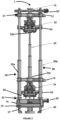
- subsea assist snubbing jack 1 comprises a plurality of jack legs, generally referred to herein as callout 20 with exemplary ones as 20a,20b; one or more leg actuators 28 operatively connected to a predetermined set of jack legs of the plurality of jack legs 20; first slip bowl 34 disposed at least partially within the plurality of jack legs 20; second slip bowl 32 movingly disposed at least partially within the plurality of jack legs 20 distally from first slip bowl 34 where second slip bowl 32 is operatively connected to the plurality of jack legs 20; control system 80 ( Fig.
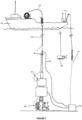
- leg actuator 28 operatively in communication with the plurality of jack legs 20, first slip bowl 34, and second slip bowl 32 and software operative to adjust each leg 20a, 20b and leg pair of the plurality of jack legs 20 to ensure that pipe 116 ( Fig. 1 ) is being snubbed into well 200 ( Fig . 1 ) concentrically.
- two jack legs 20a,20b of the plurality of jack legs 20 are disposed diagonally with respect to each other and the diagonally disposed pair of jack legs 20 are configured to perform redundantly in that either diagonal pair 20a,20b can perform a desired snubbing operation and either can be disengaged while still in operation on the well should there be a jack leg failure.
- the diagonally disposed pair of jack legs 20 is configured to be disengaged while still in operation on the well should there be a jack leg failure of one of the diagonally disposed pair of jack legs.
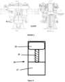
- first slip bowl 34 and second slip bowl 32 can hold light or heavy pipe loads and are adapted to create a clamping load internally, do not rely on pipe weight or the force of the subsea jack to develop clamping force, and do not require pipe motion to unseat the clamp on the pipe.
- at least one of first slip bowl 34 and second slip bowl 32 can traverse bi-directionally within the plurality of jack legs 20.
- first slip bowl 34 is fixed within the plurality of jack legs 20 and second slip bowl 32 travels within the plurality of jack legs 20 such as by having second slip bowl 32 slidingly connected to the plurality of jack legs 20.
- traveling bracket 52 may be present and connected to first end 21 of the plurality of jack legs 20 and to second slip bowl 32 and fixed bracket 14 connected to second end 23 of the plurality of jack legs 20 distally from traveling bracket 52 and to first slip bowl 34.
- leg actuator 28 is typically powered by or otherwise comprises a subsea electric motor such as electric motor 27 and may comprises a set of actuators, each leg actuator 28 of the set of actuators operatively connected to a corresponding jack leg 20 of the predetermined set of jack legs 20.
- leg actuator 28 comprises power screw 25, nut 26 cooperatively in communication with power screw 25, and motor 27 operatively in communication with power screw 25 and adapted to provide power to power screw 25.
- subsea assist snubbing jack 1 typically further comprises telescoping guide 22 disposed within the plurality of jack legs 20 where telescoping guide 22 is in communication with first slip bowl 34 and second slip bowl 32.
- Telescoping guide 22 comprises first end 22a connected to first slip bowl 34 and second end 22b connected to second slip bowl 32.
- control system 80 may comprise a monitor (not shown in the figures) and, in an embodiment, may be located subsea at or proximate to subsea assist snubbing jack 1 if there is a requirement for high response times, e.g. where lag time for surface communications is too large.
- Control system 80 may further comprise an electrical control system, comprising electronic controller 84, software comprising a programmable motion sequencer adapted to respond to match current metocean conditions, and a set of programmed interlocks 86 to ensure that a pipe being snubbed is restrained.
- metocean conditions are conditions related to the syllabic abbreviation of meteorology and physical oceanography.
- electronic controller 84 can be located proximate to, collocated with, or as part of control system 80 at a location that is not subsea.
- subsea assist snubbing jack 1 further comprises one or more interfaces 12 adapted to communicate with a pipe handling system such as might be present on vessel 100 to control motion of the pipe through the water when required.
- Control system 80 may further be operatively in communication with one or more sensors 60 configured to directly measure pipe weight being held by first slip bowl 34 and/or second slip bowl 32.
- subsea assist snubbing jack 1 further comprises one or more control interfaces 40 and control system 80 ( Fig . 1 ) is further operatively in communication with remote controller 110 ( Fig . 1 ) configured to provide subsea control by wire or wireless operation such as via control interface 40.
- control interface 40 is configured to provide an electrical interface to a subsea vehicle, e.g. remotely operated vehicle (ROV) 400 ( Fig . 1 ) or an autonomous underwater vehicle (AUV) (not specifically shown in the figures but similar to ROV 400), to allow the subsea vehicle to at least partially control leg actuator 28 such as by effecting screw adjustment and drive.
- ROV remotely operated vehicle
- AUV autonomous underwater vehicle
- Subsea assist snubbing jack 1 may further comprising a predetermined set of smooth faced inserts 70 that do not mark a pipe.
- subsea assist snubbing jack 1 can be used and is therefore practical for use in deeper water.
- subsea assist snubbing jack 1 uses power screw and "nut" system as a jack leg and use one or more subsea electric motors to power the screws.
Landscapes
- Engineering & Computer Science (AREA)
- Life Sciences & Earth Sciences (AREA)
- Geology (AREA)
- Mining & Mineral Resources (AREA)
- Physics & Mathematics (AREA)
- Environmental & Geological Engineering (AREA)
- Fluid Mechanics (AREA)
- General Life Sciences & Earth Sciences (AREA)
- Geochemistry & Mineralogy (AREA)
- Mechanical Engineering (AREA)
- Earth Drilling (AREA)
Claims (15)
- Unterstützender Unterwasser-Snubbing-Heber, der Folgendes umfasst:a. mehrere Heberschenkel (20),b. ein Schenkelbetätigungselement (28), das funktionsmäßig mit einem vorgegebenen Satz von Heberschenkeln der mehreren Heberschenkel verbunden ist,c. einen ersten Rohrkeiltopf (34), der zumindest teilweise innerhalb der mehreren Heberschenkel angeordnet ist,d. einen zweiten Rohrkeiltopf (32), der beweglich zumindest teilweise innerhalb der mehreren Heberschenkel distal von dem ersten Rohrkeiltopf angeordnet ist, wobei der zweite Rohrkeiltopf funktionsmäßig mit den mehreren Heberschenkeln verbunden ist,e. ein Steuersystem (80), das funktionsmäßig mit dem Schenkelbetätigungselement (28) kommuniziert, wobei das Steuersystem Folgendes umfasst:i. einen Monitor, der funktionsmäßig mit den mehreren Heberschenkeln, dem ersten Rohrkeiltopf und dem zweiten Rohrkeiltopf kommuniziert, undii. Software, die dazu dient, jeden Schenkel und jedes Paar der mehreren Heberschenkel zu justieren, um zu gewährleisten, dass ein Rohr konzentrisch unter Druck in ein Bohrloch eingeführt wird, undf. einen vorgegebenen Satz glattflächiger Einsätze (70), die keine Spuren auf einem Rohr hinterlassen.
- Unterstützender Unterwasser-Snubbing-Heber nach Anspruch 1, wobei zwei Heberschenkel (20a, 20b) der mehreren Heberschenkel diagonal zueinander angeordnet sind, wobei das diagonal angeordnete Paar von Heberschenkeln dafür gestaltet ist, insofern redundant zu arbeiten, als jedes beliebige diagonale Paar einen gewünschten Snubbing-Vorgang durchführen kann und jedes entkoppelt werden kann, während es noch am Bohrloch in Betrieb ist, falls ein Heberschenkelausfall auftreten sollte, und optional
wobei das diagonal angeordnete Paar von Heberschenkeln dafür gestaltet ist, entkoppelt zu werden, während es noch am Bohrloch in Betrieb ist, falls ein Heberschenkelausfall eines Schenkels des diagonal angeordneten Paares von Heberschenkeln auftreten sollte. - Unterstützender Unterwasser-Snubbing-Heber nach Anspruch 1, wobei das Steuersystem (80) ferner ein elektrisches Steuersystem umfasst, das Folgendes umfasst:a. eine elektronische Steuerung (84) undb. Software, die eine programmierbare Bewegungsablaufsteuerung umfasst, die dafür eingerichtet ist, aktuellen Metocean-Bedingungen entsprechend zu reagieren, undc. einen Satz programmierter Verriegelungen (86), um zu gewährleisten, dass ein Rohr, das gerade mit Druck eingeführt wird, festgehalten wird.
- Unterstützender Unterwasser-Snubbing-Heber nach Anspruch 1, ferner umfassend eine Schnittstelle (12), die dafür eingerichtet ist, mit einem Rohrhandhabungssystem auf einem Wasserfahrzeug zu kommunizieren, um die Bewegung des Rohrs durch das Wasser bei Bedarf zu steuern.
- Unterstützender Unterwasser-Snubbing-Heber nach Anspruch 1, wobei mindestens einer des ersten Rohrkeiltopfs (34) und des zweiten Rohrkeiltopfs (32) bidirektional innerhalb der mehreren Heberschenkel verfahren kann.
- Unterstützender Unterwasser-Snubbing-Heber nach Anspruch 1, wobei der erste Rohrkeiltopf (34) innerhalb der mehreren Heberschenkel ortsfest ist.
- Unterstützender Unterwasser-Snubbing-Heber nach Anspruch 1, wobei der erste Rohrkeiltopf (34) und der zweite Rohrkeiltopf (32) dafür eingerichtet sind, intern eine Klemmlast zu erzeugen, und nicht auf das Rohrgewicht oder die Kraft des Unterwasser-Hebers angewiesen sind, um Klemmkraft zu entwickeln.
- Unterstützender Unterwasser-Snubbing-Heber nach Anspruch 1, wobei der Snubbing-Heber dafür gestaltet ist, keine Rohrbewegung zu erfordern, um den unterstützenden Unterwasser-Snubbing-Heber vom Sitz abzuheben.
- Unterstützender Unterwasser-Snubbing-Heber nach Anspruch 1, wobei das Steuersystem ferner funktionsmäßig mit einem Sensor (60) kommuniziert, der dafür gestaltet ist, ein Rohrgewicht, das von entweder dem ersten Rohrkeiltopf oder dem zweiten Rohrkeiltopf gehalten wird, direkt zu messen.
- Unterstützender Unterwasser-Snubbing-Heber nach Anspruch 1, wobei:a. der unterstützende Unterwasser-Snubbing-Heber ferner eine Steuerschnittstelle (40) umfasst undb. das Steuersystem (80) ferner funktionsmäßig mit einer Fernsteuerung (110) kommuniziert, die dafür gestaltet ist, Unterwasser-Steuerung durch drahtgebundene Bedienung über die Steuerschnittstelle bereitzustellen, und optionalwobei die Steuerschnittstelle dafür gestaltet ist, eine elektrische Schnittstelle für ein Unterwasserfahrzeug bereitzustellen, um es dem Unterwasserfahrzeug zu ermöglichen, das Schenkelbetätigungselement (28) des unterstützenden Unterwasser-Snubbing-Hebers zumindest teilweise zu steuern.
- Unterstützender Unterwasser-Snubbing-Heber nach Anspruch 1, der ferner eine teleskopische Führung (22) umfasst, die innerhalb der mehreren Heberschenkel (20a, 20b) angeordnet ist, wobei die teleskopische Führung (22) mit dem ersten Rohrkeiltopf (34) und dem zweiten Rohrkeiltopf (32) kommuniziert, und optional
wobei die teleskopische Führung (22) ein erstes Ende (22a), das mit dem ersten Rohrkeiltopf (34) verbunden ist, und ein zweites Ende (22b), das mit dem zweiten Rohrkeiltopf (32) verbunden ist, umfasst. - Unterstützender Unterwasser-Snubbing-Heber nach Anspruch 1, wobei der zweite Rohrkeiltopf (32) verschiebbar mit den mehreren Heberschenkeln verbunden ist.
- Unterstützender Unterwasser-Snubbing-Heber nach Anspruch 1, der ferner Folgendes umfasst:a. eine sich bewegende Halterung (52), die mit einem ersten Ende (21) der mehreren Heberschenkel (20a, 20b) und mit dem zweiten Rohrkeiltopf (32) verbunden ist, undb. eine ortsfeste Halterung (14), die mit einem zweiten Ende der mehreren Heberschenkel (20a, 20b), distal der sich bewegenden Halterung angeordnet, und mit dem ersten Rohrkeiltopf (34) verbunden ist.
- Unterstützender Unterwasser-Snubbing-Heber nach Anspruch 1, wobei das Schenkelbetätigungselement (28) einen Satz von Betätigungselementen umfasst, wobei jedes Schenkelbetätigungselement des Satzes von Betätigungselementen funktionsmäßig mit einem entsprechenden Heberschenkel (20) des vorgegebenen Satzes von Heberschenkeln verbunden ist.
- Unterstützender Unterwasser-Snubbing-Heber nach Anspruch 1, wobei das Schenkelbetätigungselement (28) Folgendes umfasst:a. eine Gewindespindel (25),b. eine Mutter (26), die zusammenwirkend mit der Gewindespindel kommuniziert, undc. einen Motor (27), der zusammenwirkend mit der Gewindespindel kommuniziert und dafür eingerichtet ist, die Gewindespindel anzutreiben.
Applications Claiming Priority (2)
| Application Number | Priority Date | Filing Date | Title |
|---|---|---|---|
| US201962924048P | 2019-10-21 | 2019-10-21 | |
| PCT/US2020/056598 WO2021081050A1 (en) | 2019-10-21 | 2020-10-21 | Subsea assist snubbing jack |
Publications (3)
| Publication Number | Publication Date |
|---|---|
| EP4028629A1 EP4028629A1 (de) | 2022-07-20 |
| EP4028629A4 EP4028629A4 (de) | 2023-09-27 |
| EP4028629B1 true EP4028629B1 (de) | 2024-10-02 |
Family
ID=75619494
Family Applications (1)
| Application Number | Title | Priority Date | Filing Date |
|---|---|---|---|
| EP20879243.2A Active EP4028629B1 (de) | 2019-10-21 | 2020-10-21 | Unterwasserunterstützende verrohrungshubwinde |
Country Status (3)
| Country | Link |
|---|---|
| US (1) | US11236574B2 (de) |
| EP (1) | EP4028629B1 (de) |
| WO (1) | WO2021081050A1 (de) |
Families Citing this family (1)
| Publication number | Priority date | Publication date | Assignee | Title |
|---|---|---|---|---|
| CN119777754A (zh) * | 2025-03-10 | 2025-04-08 | 塞纳博科石油技术服务有限公司 | 一种可加式和美式安装模式转换的带压作业机及转换方法 |
Family Cites Families (13)
| Publication number | Priority date | Publication date | Assignee | Title |
|---|---|---|---|---|
| US5732909A (en) * | 1996-06-26 | 1998-03-31 | Carlos A. Torres | Pipe gripping system and method |
| GB0101259D0 (en) * | 2001-01-18 | 2001-02-28 | Wellserv Plc | Apparatus and method |
| EP1540130B1 (de) * | 2002-06-28 | 2015-01-14 | Vetco Gray Scandinavia AS | Anordnung und verfahren zum einwirken auf eine unterwasserbohrung |
| US7314087B2 (en) * | 2005-03-07 | 2008-01-01 | Halliburton Energy Services, Inc. | Heave compensation system for hydraulic workover |
| US20080053661A1 (en) * | 2006-08-30 | 2008-03-06 | Kelly Funk | Pipe guides and methods of guiding pipes in snubbing units |
| US8720582B2 (en) * | 2010-05-19 | 2014-05-13 | Baker Hughes Incorporated | Apparatus and methods for providing tubing into a subsea well |
| US8573312B2 (en) * | 2010-12-23 | 2013-11-05 | Tesco Corporation | Apparatus for applying an axial force to well pipe slips |
| CA2739280A1 (en) * | 2011-05-05 | 2012-11-05 | Snubco Manufacturing Inc. | System and method for monitoring and controlling snubbing slips |
| US8863846B2 (en) * | 2012-01-31 | 2014-10-21 | Cudd Pressure Control, Inc. | Method and apparatus to perform subsea or surface jacking |
| US10352114B2 (en) * | 2015-02-23 | 2019-07-16 | Oceaneering International, Inc. | Guide apparatus for tubular members in a snubbing unit |
| US9822613B2 (en) * | 2016-03-09 | 2017-11-21 | Oceaneering International, Inc. | System and method for riserless subsea well interventions |
| US9970243B2 (en) * | 2016-07-28 | 2018-05-15 | Oceaneering International, Inc. | Snubbing unit for inserting tubular members without a riser |
| CA3083129A1 (en) * | 2017-11-24 | 2019-05-31 | Snubbertech Ltd. | Integrated snubbing operating platform |
-
2020
- 2020-10-21 EP EP20879243.2A patent/EP4028629B1/de active Active
- 2020-10-21 US US17/076,086 patent/US11236574B2/en active Active
- 2020-10-21 WO PCT/US2020/056598 patent/WO2021081050A1/en not_active Ceased
Also Published As
| Publication number | Publication date |
|---|---|
| US11236574B2 (en) | 2022-02-01 |
| BR112022007363A2 (pt) | 2022-09-20 |
| WO2021081050A1 (en) | 2021-04-29 |
| EP4028629A1 (de) | 2022-07-20 |
| US20210140261A1 (en) | 2021-05-13 |
| EP4028629A4 (de) | 2023-09-27 |
Similar Documents
| Publication | Publication Date | Title |
|---|---|---|
| US20210164304A1 (en) | Dual device apparatus and methods usable in well drilling and other operations | |
| US4208158A (en) | Auxiliary offshore rig and methods for using same | |
| AU2010236911B2 (en) | System and method for communicating about a wellsite | |
| US4611662A (en) | Remotely operable releasable pipe connector | |
| EP4194661A1 (de) | Modularer oberer antrieb | |
| US10648294B2 (en) | Subsea control pod deployment and retrieval systems and methods | |
| GB2457349A (en) | A riserless subsea well blowout preventer | |
| EP1461509B1 (de) | Verfahren und vorrichtung zur verhinderung des rutschens von rohren | |
| US20160024892A1 (en) | Offshore Well System with a Subsea Pressure Control System Movable with a Remotely Operated Vehicle | |
| WO2016118714A1 (en) | Wellhead-mounted hydraulic workover unit | |
| US20250020037A1 (en) | System and method for remotely controlling a running tool | |
| CA2974602C (en) | Tubular pin control system | |
| US11236574B2 (en) | Subsea assist snubbing jack | |
| WO2017072535A1 (en) | Tubular systems and methods | |
| AU2008293123A1 (en) | Method and device for removing the upper portion of a well | |
| GB2071734A (en) | Auxiliary offshore rig | |
| EP2690249B1 (de) | Eingriffausbesserungs-Steuerungssysteme | |
| EP3359770A1 (de) | Steigrohrverfahren und -vorrichtungen | |
| US20120085550A1 (en) | Method and apparatus for stabbing tubular goods | |
| BR112022007363B1 (pt) | Macaco de inserção de assistência submarina | |
| US7650942B2 (en) | Sub sea control and monitoring system | |
| CA2527463A1 (en) | Case alignment tool | |
| EP3283723B1 (de) | Steigrohrsteuerungsinnenadapter und verfahren zur verwendung | |
| NO20251366A1 (en) | Riserless subsea coiled tubing intervention automation | |
| NO20120559A1 (no) | Koblingsapparat for å forbinde to borerørseksjoner og en fremgangsmåte for bruk av samme |
Legal Events
| Date | Code | Title | Description |
|---|---|---|---|
| STAA | Information on the status of an ep patent application or granted ep patent |
Free format text: STATUS: THE INTERNATIONAL PUBLICATION HAS BEEN MADE |
|
| PUAI | Public reference made under article 153(3) epc to a published international application that has entered the european phase |
Free format text: ORIGINAL CODE: 0009012 |
|
| STAA | Information on the status of an ep patent application or granted ep patent |
Free format text: STATUS: REQUEST FOR EXAMINATION WAS MADE |
|
| 17P | Request for examination filed |
Effective date: 20220412 |
|
| AK | Designated contracting states |
Kind code of ref document: A1 Designated state(s): AL AT BE BG CH CY CZ DE DK EE ES FI FR GB GR HR HU IE IS IT LI LT LU LV MC MK MT NL NO PL PT RO RS SE SI SK SM TR |
|
| DAV | Request for validation of the european patent (deleted) | ||
| DAX | Request for extension of the european patent (deleted) | ||
| P01 | Opt-out of the competence of the unified patent court (upc) registered |
Effective date: 20230526 |
|
| REG | Reference to a national code |
Ref country code: DE Ref legal event code: R079 Free format text: PREVIOUS MAIN CLASS: E21B0019000000 Ipc: E21B0019080000 Ref country code: DE Ref legal event code: R079 Ref document number: 602020038848 Country of ref document: DE Free format text: PREVIOUS MAIN CLASS: E21B0019000000 Ipc: E21B0019080000 |
|
| A4 | Supplementary search report drawn up and despatched |
Effective date: 20230828 |
|
| RIC1 | Information provided on ipc code assigned before grant |
Ipc: E21B 33/076 20060101ALI20230822BHEP Ipc: E21B 33/038 20060101ALI20230822BHEP Ipc: E21B 29/00 20060101ALI20230822BHEP Ipc: E21B 19/16 20060101ALI20230822BHEP Ipc: E21B 19/10 20060101ALI20230822BHEP Ipc: E21B 17/00 20060101ALI20230822BHEP Ipc: E21B 19/08 20060101AFI20230822BHEP |
|
| GRAP | Despatch of communication of intention to grant a patent |
Free format text: ORIGINAL CODE: EPIDOSNIGR1 |
|
| STAA | Information on the status of an ep patent application or granted ep patent |
Free format text: STATUS: GRANT OF PATENT IS INTENDED |
|
| RIC1 | Information provided on ipc code assigned before grant |
Ipc: E21B 33/076 20060101ALI20240325BHEP Ipc: E21B 33/038 20060101ALI20240325BHEP Ipc: E21B 29/00 20060101ALI20240325BHEP Ipc: E21B 19/16 20060101ALI20240325BHEP Ipc: E21B 19/10 20060101ALI20240325BHEP Ipc: E21B 17/00 20060101ALI20240325BHEP Ipc: E21B 19/08 20060101AFI20240325BHEP |
|
| INTG | Intention to grant announced |
Effective date: 20240425 |
|
| GRAS | Grant fee paid |
Free format text: ORIGINAL CODE: EPIDOSNIGR3 |
|
| GRAA | (expected) grant |
Free format text: ORIGINAL CODE: 0009210 |
|
| STAA | Information on the status of an ep patent application or granted ep patent |
Free format text: STATUS: THE PATENT HAS BEEN GRANTED |
|
| AK | Designated contracting states |
Kind code of ref document: B1 Designated state(s): AL AT BE BG CH CY CZ DE DK EE ES FI FR GB GR HR HU IE IS IT LI LT LU LV MC MK MT NL NO PL PT RO RS SE SI SK SM TR |
|
| RAP3 | Party data changed (applicant data changed or rights of an application transferred) |
Owner name: OCEANEERING INTERNATIONAL, INC. |
|
| REG | Reference to a national code |
Ref country code: GB Ref legal event code: FG4D |
|
| REG | Reference to a national code |
Ref country code: CH Ref legal event code: EP |
|
| REG | Reference to a national code |
Ref country code: DE Ref legal event code: R096 Ref document number: 602020038848 Country of ref document: DE |
|
| REG | Reference to a national code |
Ref country code: IE Ref legal event code: FG4D |
|
| REG | Reference to a national code |
Ref country code: LT Ref legal event code: MG9D |
|
| REG | Reference to a national code |
Ref country code: NL Ref legal event code: MP Effective date: 20241002 |
|
| REG | Reference to a national code |
Ref country code: AT Ref legal event code: MK05 Ref document number: 1728635 Country of ref document: AT Kind code of ref document: T Effective date: 20241002 |
|
| PG25 | Lapsed in a contracting state [announced via postgrant information from national office to epo] |
Ref country code: NL Free format text: LAPSE BECAUSE OF FAILURE TO SUBMIT A TRANSLATION OF THE DESCRIPTION OR TO PAY THE FEE WITHIN THE PRESCRIBED TIME-LIMIT Effective date: 20241002 |
|
| PG25 | Lapsed in a contracting state [announced via postgrant information from national office to epo] |
Ref country code: NL Free format text: LAPSE BECAUSE OF FAILURE TO SUBMIT A TRANSLATION OF THE DESCRIPTION OR TO PAY THE FEE WITHIN THE PRESCRIBED TIME-LIMIT Effective date: 20241002 |
|
| PG25 | Lapsed in a contracting state [announced via postgrant information from national office to epo] |
Ref country code: IS Free format text: LAPSE BECAUSE OF FAILURE TO SUBMIT A TRANSLATION OF THE DESCRIPTION OR TO PAY THE FEE WITHIN THE PRESCRIBED TIME-LIMIT Effective date: 20250202 Ref country code: PT Free format text: LAPSE BECAUSE OF FAILURE TO SUBMIT A TRANSLATION OF THE DESCRIPTION OR TO PAY THE FEE WITHIN THE PRESCRIBED TIME-LIMIT Effective date: 20250203 Ref country code: HR Free format text: LAPSE BECAUSE OF FAILURE TO SUBMIT A TRANSLATION OF THE DESCRIPTION OR TO PAY THE FEE WITHIN THE PRESCRIBED TIME-LIMIT Effective date: 20241002 |
|
| PG25 | Lapsed in a contracting state [announced via postgrant information from national office to epo] |
Ref country code: FI Free format text: LAPSE BECAUSE OF FAILURE TO SUBMIT A TRANSLATION OF THE DESCRIPTION OR TO PAY THE FEE WITHIN THE PRESCRIBED TIME-LIMIT Effective date: 20241002 |
|
| PG25 | Lapsed in a contracting state [announced via postgrant information from national office to epo] |
Ref country code: BG Free format text: LAPSE BECAUSE OF FAILURE TO SUBMIT A TRANSLATION OF THE DESCRIPTION OR TO PAY THE FEE WITHIN THE PRESCRIBED TIME-LIMIT Effective date: 20241002 |
|
| PG25 | Lapsed in a contracting state [announced via postgrant information from national office to epo] |
Ref country code: ES Free format text: LAPSE BECAUSE OF FAILURE TO SUBMIT A TRANSLATION OF THE DESCRIPTION OR TO PAY THE FEE WITHIN THE PRESCRIBED TIME-LIMIT Effective date: 20241002 |
|
| PG25 | Lapsed in a contracting state [announced via postgrant information from national office to epo] |
Ref country code: LV Free format text: LAPSE BECAUSE OF FAILURE TO SUBMIT A TRANSLATION OF THE DESCRIPTION OR TO PAY THE FEE WITHIN THE PRESCRIBED TIME-LIMIT Effective date: 20241002 Ref country code: AT Free format text: LAPSE BECAUSE OF FAILURE TO SUBMIT A TRANSLATION OF THE DESCRIPTION OR TO PAY THE FEE WITHIN THE PRESCRIBED TIME-LIMIT Effective date: 20241002 Ref country code: GR Free format text: LAPSE BECAUSE OF FAILURE TO SUBMIT A TRANSLATION OF THE DESCRIPTION OR TO PAY THE FEE WITHIN THE PRESCRIBED TIME-LIMIT Effective date: 20250103 |
|
| PG25 | Lapsed in a contracting state [announced via postgrant information from national office to epo] |
Ref country code: PL Free format text: LAPSE BECAUSE OF FAILURE TO SUBMIT A TRANSLATION OF THE DESCRIPTION OR TO PAY THE FEE WITHIN THE PRESCRIBED TIME-LIMIT Effective date: 20241002 Ref country code: CZ Free format text: LAPSE BECAUSE OF FAILURE TO SUBMIT A TRANSLATION OF THE DESCRIPTION OR TO PAY THE FEE WITHIN THE PRESCRIBED TIME-LIMIT Effective date: 20241002 |
|
| PG25 | Lapsed in a contracting state [announced via postgrant information from national office to epo] |
Ref country code: RS Free format text: LAPSE BECAUSE OF FAILURE TO SUBMIT A TRANSLATION OF THE DESCRIPTION OR TO PAY THE FEE WITHIN THE PRESCRIBED TIME-LIMIT Effective date: 20250102 |
|
| REG | Reference to a national code |
Ref country code: DE Ref legal event code: R119 Ref document number: 602020038848 Country of ref document: DE |
|
| REG | Reference to a national code |
Ref country code: CH Ref legal event code: PL |
|
| PG25 | Lapsed in a contracting state [announced via postgrant information from national office to epo] |
Ref country code: SM Free format text: LAPSE BECAUSE OF FAILURE TO SUBMIT A TRANSLATION OF THE DESCRIPTION OR TO PAY THE FEE WITHIN THE PRESCRIBED TIME-LIMIT Effective date: 20241002 |
|
| PG25 | Lapsed in a contracting state [announced via postgrant information from national office to epo] |
Ref country code: MC Free format text: LAPSE BECAUSE OF FAILURE TO SUBMIT A TRANSLATION OF THE DESCRIPTION OR TO PAY THE FEE WITHIN THE PRESCRIBED TIME-LIMIT Effective date: 20241002 |
|
| PG25 | Lapsed in a contracting state [announced via postgrant information from national office to epo] |
Ref country code: DE Free format text: LAPSE BECAUSE OF NON-PAYMENT OF DUE FEES Effective date: 20250501 |
|
| PG25 | Lapsed in a contracting state [announced via postgrant information from national office to epo] |
Ref country code: DK Free format text: LAPSE BECAUSE OF FAILURE TO SUBMIT A TRANSLATION OF THE DESCRIPTION OR TO PAY THE FEE WITHIN THE PRESCRIBED TIME-LIMIT Effective date: 20241002 |
|
| PG25 | Lapsed in a contracting state [announced via postgrant information from national office to epo] |
Ref country code: LU Free format text: LAPSE BECAUSE OF NON-PAYMENT OF DUE FEES Effective date: 20241021 Ref country code: BE Free format text: LAPSE BECAUSE OF NON-PAYMENT OF DUE FEES Effective date: 20241031 |
|
| PG25 | Lapsed in a contracting state [announced via postgrant information from national office to epo] |
Ref country code: EE Free format text: LAPSE BECAUSE OF FAILURE TO SUBMIT A TRANSLATION OF THE DESCRIPTION OR TO PAY THE FEE WITHIN THE PRESCRIBED TIME-LIMIT Effective date: 20241002 |
|
| PG25 | Lapsed in a contracting state [announced via postgrant information from national office to epo] |
Ref country code: CH Free format text: LAPSE BECAUSE OF NON-PAYMENT OF DUE FEES Effective date: 20241031 |
|
| PG25 | Lapsed in a contracting state [announced via postgrant information from national office to epo] |
Ref country code: RO Free format text: LAPSE BECAUSE OF FAILURE TO SUBMIT A TRANSLATION OF THE DESCRIPTION OR TO PAY THE FEE WITHIN THE PRESCRIBED TIME-LIMIT Effective date: 20241002 |
|
| PG25 | Lapsed in a contracting state [announced via postgrant information from national office to epo] |
Ref country code: SK Free format text: LAPSE BECAUSE OF FAILURE TO SUBMIT A TRANSLATION OF THE DESCRIPTION OR TO PAY THE FEE WITHIN THE PRESCRIBED TIME-LIMIT Effective date: 20241002 |
|
| PG25 | Lapsed in a contracting state [announced via postgrant information from national office to epo] |
Ref country code: IT Free format text: LAPSE BECAUSE OF FAILURE TO SUBMIT A TRANSLATION OF THE DESCRIPTION OR TO PAY THE FEE WITHIN THE PRESCRIBED TIME-LIMIT Effective date: 20241002 |
|
| REG | Reference to a national code |
Ref country code: BE Ref legal event code: MM Effective date: 20241031 |
|
| PLBE | No opposition filed within time limit |
Free format text: ORIGINAL CODE: 0009261 |
|
| STAA | Information on the status of an ep patent application or granted ep patent |
Free format text: STATUS: NO OPPOSITION FILED WITHIN TIME LIMIT |
|
| PG25 | Lapsed in a contracting state [announced via postgrant information from national office to epo] |
Ref country code: SE Free format text: LAPSE BECAUSE OF FAILURE TO SUBMIT A TRANSLATION OF THE DESCRIPTION OR TO PAY THE FEE WITHIN THE PRESCRIBED TIME-LIMIT Effective date: 20241002 |
|
| 26N | No opposition filed |
Effective date: 20250703 |
|
| PG25 | Lapsed in a contracting state [announced via postgrant information from national office to epo] |
Ref country code: FR Free format text: LAPSE BECAUSE OF NON-PAYMENT OF DUE FEES Effective date: 20241202 |
|
| PG25 | Lapsed in a contracting state [announced via postgrant information from national office to epo] |
Ref country code: IE Free format text: LAPSE BECAUSE OF NON-PAYMENT OF DUE FEES Effective date: 20241021 |
|
| PGFP | Annual fee paid to national office [announced via postgrant information from national office to epo] |
Ref country code: NO Payment date: 20251229 Year of fee payment: 6 |
|
| PG25 | Lapsed in a contracting state [announced via postgrant information from national office to epo] |
Ref country code: CY Free format text: LAPSE BECAUSE OF FAILURE TO SUBMIT A TRANSLATION OF THE DESCRIPTION OR TO PAY THE FEE WITHIN THE PRESCRIBED TIME-LIMIT; INVALID AB INITIO Effective date: 20201021 |
|
| PG25 | Lapsed in a contracting state [announced via postgrant information from national office to epo] |
Ref country code: HU Free format text: LAPSE BECAUSE OF FAILURE TO SUBMIT A TRANSLATION OF THE DESCRIPTION OR TO PAY THE FEE WITHIN THE PRESCRIBED TIME-LIMIT; INVALID AB INITIO Effective date: 20201021 |
|
| PGFP | Annual fee paid to national office [announced via postgrant information from national office to epo] |
Ref country code: GB Payment date: 20260106 Year of fee payment: 6 |