EP4028155B1 - Pulsed electric field chamber - Google Patents
Pulsed electric field chamber Download PDFInfo
- Publication number
- EP4028155B1 EP4028155B1 EP20862456.9A EP20862456A EP4028155B1 EP 4028155 B1 EP4028155 B1 EP 4028155B1 EP 20862456 A EP20862456 A EP 20862456A EP 4028155 B1 EP4028155 B1 EP 4028155B1
- Authority
- EP
- European Patent Office
- Prior art keywords
- pef
- flow
- electrode units
- chamber
- tube
- Prior art date
- Legal status (The legal status is an assumption and is not a legal conclusion. Google has not performed a legal analysis and makes no representation as to the accuracy of the status listed.)
- Active
Links
Images



Classifications
-
- C—CHEMISTRY; METALLURGY
- C02—TREATMENT OF WATER, WASTE WATER, SEWAGE, OR SLUDGE
- C02F—TREATMENT OF WATER, WASTE WATER, SEWAGE, OR SLUDGE
- C02F1/00—Treatment of water, waste water, or sewage
- C02F1/46—Treatment of water, waste water, or sewage by electrochemical methods
- C02F1/4608—Treatment of water, waste water, or sewage by electrochemical methods using electrical discharges
-
- A—HUMAN NECESSITIES
- A23—FOODS OR FOODSTUFFS; TREATMENT THEREOF, NOT COVERED BY OTHER CLASSES
- A23B—PRESERVATION OF FOODS, FOODSTUFFS OR NON-ALCOHOLIC BEVERAGES; CHEMICAL RIPENING OF FRUIT OR VEGETABLES
- A23B2/00—Preservation of foods or foodstuffs, in general
- A23B2/60—Preservation of foods or foodstuffs, in general by treatment with electric currents without heating effect
-
- A—HUMAN NECESSITIES
- A23—FOODS OR FOODSTUFFS; TREATMENT THEREOF, NOT COVERED BY OTHER CLASSES
- A23L—FOODS, FOODSTUFFS OR NON-ALCOHOLIC BEVERAGES, NOT OTHERWISE PROVIDED FOR; PREPARATION OR TREATMENT THEREOF
- A23L5/00—Preparation or treatment of foods or foodstuffs, in general; Food or foodstuffs obtained thereby; Materials therefor
- A23L5/30—Physical treatment, e.g. electrical or magnetic means, wave energy or irradiation
-
- B—PERFORMING OPERATIONS; TRANSPORTING
- B01—PHYSICAL OR CHEMICAL PROCESSES OR APPARATUS IN GENERAL
- B01J—CHEMICAL OR PHYSICAL PROCESSES, e.g. CATALYSIS OR COLLOID CHEMISTRY; THEIR RELEVANT APPARATUS
- B01J19/00—Chemical, physical or physico-chemical processes in general; Their relevant apparatus
- B01J19/08—Processes employing the direct application of electric or wave energy, or particle radiation; Apparatus therefor
- B01J19/087—Processes employing the direct application of electric or wave energy, or particle radiation; Apparatus therefor employing electric or magnetic energy
-
- C—CHEMISTRY; METALLURGY
- C02—TREATMENT OF WATER, WASTE WATER, SEWAGE, OR SLUDGE
- C02F—TREATMENT OF WATER, WASTE WATER, SEWAGE, OR SLUDGE
- C02F1/00—Treatment of water, waste water, or sewage
- C02F1/46—Treatment of water, waste water, or sewage by electrochemical methods
- C02F1/461—Treatment of water, waste water, or sewage by electrochemical methods by electrolysis
- C02F1/46104—Devices therefor; Their operating or servicing
-
- A—HUMAN NECESSITIES
- A23—FOODS OR FOODSTUFFS; TREATMENT THEREOF, NOT COVERED BY OTHER CLASSES
- A23L—FOODS, FOODSTUFFS OR NON-ALCOHOLIC BEVERAGES, NOT OTHERWISE PROVIDED FOR; PREPARATION OR TREATMENT THEREOF
- A23L5/00—Preparation or treatment of foods or foodstuffs, in general; Food or foodstuffs obtained thereby; Materials therefor
- A23L5/30—Physical treatment, e.g. electrical or magnetic means, wave energy or irradiation
- A23L5/36—Physical treatment, e.g. electrical or magnetic means, wave energy or irradiation using irradiation with frequencies of more than 10 MHz
-
- C—CHEMISTRY; METALLURGY
- C02—TREATMENT OF WATER, WASTE WATER, SEWAGE, OR SLUDGE
- C02F—TREATMENT OF WATER, WASTE WATER, SEWAGE, OR SLUDGE
- C02F1/00—Treatment of water, waste water, or sewage
- C02F1/46—Treatment of water, waste water, or sewage by electrochemical methods
- C02F1/461—Treatment of water, waste water, or sewage by electrochemical methods by electrolysis
- C02F1/46104—Devices therefor; Their operating or servicing
- C02F1/46109—Electrodes
- C02F2001/46152—Electrodes characterised by the shape or form
-
- C—CHEMISTRY; METALLURGY
- C02—TREATMENT OF WATER, WASTE WATER, SEWAGE, OR SLUDGE
- C02F—TREATMENT OF WATER, WASTE WATER, SEWAGE, OR SLUDGE
- C02F2201/00—Apparatus for treatment of water, waste water or sewage
- C02F2201/46—Apparatus for electrochemical processes
- C02F2201/461—Electrolysis apparatus
- C02F2201/46105—Details relating to the electrolytic devices
- C02F2201/4616—Power supply
- C02F2201/46175—Electrical pulses
-
- C—CHEMISTRY; METALLURGY
- C02—TREATMENT OF WATER, WASTE WATER, SEWAGE, OR SLUDGE
- C02F—TREATMENT OF WATER, WASTE WATER, SEWAGE, OR SLUDGE
- C02F2301/00—General aspects of water treatment
- C02F2301/02—Fluid flow conditions
- C02F2301/024—Turbulent
Definitions
- the present invention relates to a PEF (pulsed electric field) chamber with optimal electrode geometry for continuous flows.
- PEF chambers There are existing PEF chambers.
- One such is disclosed in WO 2017/184066 where there is described a PEF chamber comprising a PEF treatment tube, a casing and at least two electrode units, wherein said at least two electrode units are insertable to be fixated in the casing and into the PEF treatment tube.
- WO 2016/171610 there is also disclosed a PEF chamber with a geometrical narrowing.
- Other PEF chambers are described in US5549041A and CN101502304B .
- the present invention refers to a PEF chamber which has a geometry and especially an electrode arrangement which are beneficial for several types of applications, such as e.g. for treating different form of food stuffs and other pumpable materials, e.g. slurries or the like.
- the PEF chamber has an optimal electrode geometry for treatment of continuous flows.
- the invention which relates to a PEF (pulsed electric field) chamber as defined in claim 1, said chamber being intended for treating a flow with electric field pulses, said PEF chamber comprising a PEF treatment tube and opposite electrode units, wherein each one of said opposite electrode units has one flow receiving end and one flow exit end, wherein the PEF treatment tube comprises exit flow portions arranged subsequent to the flow exit ends of the electrode units in the intended flow direction, and thus functioning as an extension of the opposite electrode units in the intended flow direction, wherein the exit flow portions of the PEF treatment tube are arranged to provide a geometrical narrowing subsequent to the flow exit ends.
- PEF pulsesed electric field
- the word "tube” should not be interpreted as limited to any specific geometry. Therefore, “tube” may in this be regarded as any geometry defining a certain volume of which at least a part is intended for PEF treatment.
- the PEF chamber according to the present invention is the entire system, which in turn comprises a PEF treatment tube being the part in which there is a PEF treatment volume where PEF treatment is intended. It is in this regard it should be understood that the PEF treatment volume may have many different types of geometry according to the present invention. As such, a tube is not limited to a tube geometry according to the present invention.
- US 5,662,031 there is disclosed treatment systems for treating flowable food products using electrical pulses to inactivate microbes.
- the systems described include one or more stages having flow-through processors and the flow-through processors have first and second electrodes being spaced across a treatment chamber in which an intense electrical field is generated using bipolar electrical pulses.
- US 2008/0279995 there is disclosed a process for extracting useful substances from wine grapes, said process being achieved by electroporation of the must produced from red and/or white grapes.
- the device for carrying out must electroporation comprises a dielectric pipe, the flow duct for the must, in whose wall are arranged two mutually spaced electrodes to form a pulsed electric field between the electrodes.
- the flow receiving ends are rounded in an intended flow direction into the PEF treatment tube.
- the rounded flow receiving ends of the electrodes may also be described as bent ends.
- a PEF chamber according to the present invention may be implemented in many different ways, one suitable alternative is as a vertical PEF chamber. Embodiments of such are shown in the drawings. In such a case, the flow receiving ends are positioned as lower electrode ends.
- the flow to be treated is suitably pumped up through the PEF chamber. This may be beneficial as a controlled needed pump pressure diminishes the risk for air entering into the PEF chamber.
- the PEF chamber according to the present invention may be placed in any geometrical direction and position, and is not limited to a configuration where the flow is pumped up through the chamber.
- the PEF chamber according to the present invention provides several advantages when being compared to existing PEF chambers.
- the present PEF chamber provides a strong homogenous electric field (e-field) with minimized volumes with low e-field and without so called hot spots with high e-fields, which is beneficial since the volumes with low e-field reduces efficiency and the hot spots cause volumes where the temperature increases too much.
- the PEF chamber according to the present invention provides an effective flow profile where there is a low risk of a part of the flow standing still. Such flow portions standing still are also a disadvantage for the treatment efficiency and for the risk of high temperature volumes.
- the PEF chamber according to the present invention comprises two flat parallel electrode units which expose two rectangular surfaces.
- the PEF treatment tube comprises exit flow portions arranged subsequent to the flow exit ends of the electrode units in the intended flow direction, and thus functioning as an extension of the opposite electrode units in the intended flow direction, and wherein the exit flow portions are rounded in an intended flow direction.
- this type of geometry also provides a starting point for making sure that the passing flow of material to be treated is not standing still in the crossing between the electrode units and material subsequent to the electrode units. As the edges of the isolating material subsequent to the electrodes are rounded this also enables the provision of a homogenous electric field.
- the geometrical narrowing is important for the provision of both a homogenous electric field and a channel without positions where the flow is standing still. Further embodiments and possible improvements, such as geometrical narrowing(s), of the geometry are further explained below.
- PEF treatment tube is not limited to a certain geometry.
- the PEF treatment tube should be seen as the device structure as such, i.e. part of the entire PEF chamber, and not only the treatment volume. This may be clear when reviewing the figures.
- each electrode unit is insertable into matching grooves of the PEF treatment tube of the PEF chamber.
- the electrode units are both insertable and detachable, for example arranged with screws to enable this feature.
- One such alternative is shown in the figures. As the electrodes are worn out and has to be replaced by new ones after a certain usage time, this feature may be of interest to provide.
- the opposite electrode units are longitudinal. Embodiments thereof are shown in the figures.
- the electrode units are arranged in the PEF treatment tube to provide a first geometrical narrowing at the flow receiving ends.
- One such embodiment is shown in the figures.
- this geometrical narrowing is of relevance for the provision of a homogenous electric field without hot spots and a through flow geometry where the risk of positions where the flow stands still is diminished.
- the first narrowing suitably is a lower geometrical narrowing as the flow is pumped into the chamber from a bottom and upwards.
- a geometrical narrowing according to the present invention implies that the cross section area of the PEF tube is lowered in the geometrical narrowing when compared with a point before the geometrical narrowing.
- the PEF chamber shown in WO 2017/184066 may also be arranged to provide a geometrical narrowing.
- the PEF chamber may be provided with two round electrodes arranged to form semi-circular pulse surfaces within the tube at the geometrical narrowing.
- the present invention is directed to longitudinal electrodes which ends as such provide the first geometrical narrowing. This is an important difference when being compared to the arrangement shown in fig. 4 of WO 2017/184066 where round electrodes are arranged inside of the geometrical narrowing. It should be noted that with longitudinal electrode units such as according to the present invention, the volume where there are losses are reduced.
- the end positions of the electrode units are the positions where there is an evident risk for losses in relation to the electric field provided.
- a long PEF treatment chamber i.e. with longitudinal electrode units, provides a lower level of volume where losses may exist.
- the limitation of length is decided by the maximum current in the PEF generator and the minimal cross section that the pumped material can have.
- the shape of the chamber is an optimal compromise of avoiding high electric fields and high temperature increases. If the chamber is optimized for avoiding only high electric fields, then problems with still standing zones, high temperatures and overtreatment arise. This will create burning or sparks in the liquid when it becomes steam. If the chamber is optimized for a uniform flow only, then problems with high electric field arise which cause sparks.
- the exit flow portions of the PEF treatment tube are arranged to provide a second geometrical narrowing subsequent to the flow exit ends.
- This second geometrical narrowing may then be seen as an upper geometrical narrowing in the cases of embodiments as shown in the figures where the flow is pumped from bottom up.
- the second geometrical narrowing is provided by the isolating material arranged subsequent to the electrode units.
- the second geometrical narrowing has a lower cross section area than the first geometrical narrowing.
- parallel electrode units this is a given fact, as seen in the figures.
- mechanical solutions of the first and second narrowings may be of different type.
- a relationship of a gap distance (GE) between the opposite electrode units in the PEF chamber to a length (LE) of each electrode unit has a LE/GE ratio of at least 3, preferably at least 6, more preferably at least 8, most preferably at least 10.
- This high ratio according to the present invention ensures that the relative loss volume, as explained above, is kept a low level.
- LE/GE ratio values of at least 10, even above 15, may be important for certain applications, such as e.g. when treating whey protein or dairy products. Such values are possible to obtain according to the present invention.
- a length (LE) of each electrode unit is at least 30 mm, preferably in a range of 30 - 600 mm, e.g. in a range of 50 - 600 mm, more preferably in a range of 30 - 300 mm, more preferably in a range of 30 - 200 mm, and wherein a gap distance (GE) between the opposite electrode units in the PEF chamber is at least 3 mm, preferably in a range of 3 - 45 mm.
- This type of sizes and relationship between length of the electrodes and the gap distance between the electrodes is suitable for the intended applications, such as treatment of continuous feedstuff flows, and suitable sizes of PEF generators.
- a width (WE) of each electrode unit is at least 3 mm, preferably in the range of 3 - 45 mm.
- the width is especially of interest in relation to the gap distance between the electrodes and length of electrodes.
- a relationship of a gap distance (GE) between the opposite electrode units in the PEF chamber, a length (LE) of each electrode unit and a width (WE) of each electrode unit in the form of GE:WE:LE is in a ratio of from 3:3:20 mm to 45:40:200 mm.
- the suitable exact relationships depend on the intended industrial application, such as for treating foodstuffs, and which type of them, e.g. juice or crushed fruit, or if it is other types of materials, such as sewage sludge or the like.
- the first geometrical narrowing is arranged as a gap distance (GE) between the opposite electrode units, which (GE) is in the range of 40 - 80%, preferably in the range of 45 - 64%, of a first tube distance arranged before the opposite electrode units in the intended flow direction.
- the first tube distance is thus the distance between the sides of the isolating material tube before the electrodes.
- the gap distance (GE) is constant as the electrode units suitable are parallel.
- the second geometrical narrowing is arranged with a second tube distance which is in the range of 65 - 95%, preferably in the range of 70 - 80%, of a gap distance (GE) between the opposite electrode units.
- the second tube distance is the thus the distance between the sides of the isolating material tube subsequent to the electrodes.
- the actual rounded shape of the electrode units as well as the isolating material subsequent to the electrode units may also be of importance.
- the flow receiving ends are rounded with a radius to form an angle between a material arranged before the opposite electrode units and the actual opposite electrode units in a range of 70 - 110 degrees.
- angles around 90 degrees are very suitable.
- the exit flow portions are rounded with a radius to form an angle between the flow exit ends of the electrode units and the actual exit flow portions in a range of 70 - 110 degrees. Also here angles around 90 degrees are very suitable.
- the PEF treatment tube comprises a turbulence unit, preferably a helix unit, arranged before the flow receiving ends of the electrode units.
- the turbulence unit is arranged before the electrodes in a flow direction.
- the turbulence unit is arranged to provide turbulence in the flow before the enter of the flow between the electrode units.
- a turbulent flow is more randomized which is preferable when treating a flow with electric pulses. Still standing spots in the flow are inhibited, which are occurring in laminar flows. This is preferable.
- a helix is one possible type of unit which is possible as the turbulence unit.
- a helix may imply an increased flow velocity close to edges inside of the treatment volume and tube. This may be accomplished by the provision of rotation of the flow, which may be obtained by a helix.
- the helix may as such provide a flow velocity which is more or less the same inside of the volume, and not much higher in the middle of the treatment volume.
- the PEF chamber and tube according to the present invention may also instead or in addition comprise other types of units arranged to enable a turbulence flow between the electrodes. Therefore, according to one specific embodiment of the present invention, there is one or more wings arranged on one or both chamber walls beside the opposite electrode units. On the sides of the electrodes and inside of the PEF chamber there are tube walls which do not constitute the electrodes. Here wings or other protruding units may be provided to inhibit a laminar flow profile. Such wings may be arranged as a standalone solution or in addition to a turbulence unit provided before the electrode units.
- a splitter is arranged at the end of a treatment volume of the PEF treatment tube.
- a splitter according to the present invention may decrease the e-field at the end of the electrodes.
- the high e-field spots are as such moved into the middle of the treatment volume where the flow velocity is the highest.
- Such a high e-field spot will then be provided at the beginning of the splitter.
- the splitter may be rounded in shape in this beginning of the splitter.
- the beginning of the splitter will also then have almost the highest flow velocity in the treatment volume. Therefore, the present invention may also ensure that an increased e-field is obtained where the flow velocity is high.
- the present invention is intended for treatment of continuous flows, e.g. foodstuffs or waste water or the like.
- continuous flows e.g. foodstuffs or waste water or the like.
- examples are orange juice, carrot juice, apple juice, waste water or sludge, crushed olives, crushed grapes for wine production, whey protein, dairy products, egg treatment, etc.
- the present invention provides many advantages in comparison to known PEF chambers. To summarize some of these advantages it may be mentioned that the present invention provides an effective flow profile where there is a low risk of a part of the flow standing still and deminishes the problem with hots spots where the electric field is very high at the electrode units. Moroever, the present invention also ensures that there is reduction of the chamber volume where there are losses.
- the PEF chamber 1 comprises a PEF treatment tube 2 and opposite electrode units 3, 4 which are insertable into the PEF chamber 1.
- the electrode units 3, 4 are attachable and detachable by arranged screws.
- the opposite electrode units 3, 4 each has one flow receiving end 5a, 5b and one flow exit end 6a, 6b.
- the flow to be treated is pumped into the bottom and up through the PEF chamber 1 and PEF treatment tube 2.
- the flow receiving ends 5a, 5b are rounded or bent in an intended flow direction into the PEF treatment tube 2.
- the width of the electrode units (WE) is depicted in this embodiment.
- the PEF treatment tube 2 comprises exit flow portions 7a, 7b arranged subsequent to the flow exit ends 6a, 6b of the electrode units 3, 4 in the intended flow direction.
- These exit flow portions 7a, 7b are part of the isolating material arranged subsequent to the electrode units 3, 4, thus functioning as extensions of the opposite electrode units 3, 4 in the intended flow direction.
- these exit flow portions 7a, 7b are rounded or bent in an intended flow direction.
- the electrode units 3, 4 are arranged in the PEF treatment tube 2 to provide a first geometrical narrowing 10 at the flow receiving ends 5a, 5b.
- the exit flow portions 7a, 7b of the PEF treatment tube 2 are also arranged to provide a second geometrical narrowing 20 subsequent to the flow exit ends 6a, 6b. This implies that two geometrical narrowings are provided along the flow path from, in this case, lower inflow side to the upper outflow side.
- fig. 4 there is also shown an embodiment in line with the ones shown in figs. 1-3 .
- a gap distance GE between the opposite electrode units 3, 4 in the PEF chamber and the length LE of the electrodes are also depicted.
- a first tube distance 11 arranged before the opposite electrode units 3, 4 in the intended flow direction is also depicted.
- a second tube distance 21, which is the tube diameter subsequent to the electrodes is also shown in fig. 4 .
Landscapes
- Chemical & Material Sciences (AREA)
- Life Sciences & Earth Sciences (AREA)
- Engineering & Computer Science (AREA)
- Health & Medical Sciences (AREA)
- Organic Chemistry (AREA)
- Food Science & Technology (AREA)
- Polymers & Plastics (AREA)
- Chemical Kinetics & Catalysis (AREA)
- Hydrology & Water Resources (AREA)
- Environmental & Geological Engineering (AREA)
- Water Supply & Treatment (AREA)
- Nutrition Science (AREA)
- General Chemical & Material Sciences (AREA)
- Electrochemistry (AREA)
- Zoology (AREA)
- Wood Science & Technology (AREA)
- General Health & Medical Sciences (AREA)
- Toxicology (AREA)
- Food Preservation Except Freezing, Refrigeration, And Drying (AREA)
- Physical Or Chemical Processes And Apparatus (AREA)
Description
- The present invention relates to a PEF (pulsed electric field) chamber with optimal electrode geometry for continuous flows.
- There are existing PEF chambers. One such is disclosed in
WO 2017/184066 where there is described a PEF chamber comprising a PEF treatment tube, a casing and at least two electrode units, wherein said at least two electrode units are insertable to be fixated in the casing and into the PEF treatment tube. - Furthermore, in
WO 2016/171610 there is also disclosed a PEF chamber with a geometrical narrowing. Other PEF chambers are described inUS5549041A andCN101502304B . - The present invention refers to a PEF chamber which has a geometry and especially an electrode arrangement which are beneficial for several types of applications, such as e.g. for treating different form of food stuffs and other pumpable materials, e.g. slurries or the like. As mentioned above, the PEF chamber has an optimal electrode geometry for treatment of continuous flows.
- The purpose stated above is solved by the invention, which relates to a PEF (pulsed electric field) chamber as defined in claim 1, said chamber being intended for treating a flow with electric field pulses, said PEF chamber comprising a PEF treatment tube and opposite electrode units, wherein each one of said opposite electrode units has one flow receiving end and one flow exit end, wherein the PEF treatment tube comprises exit flow portions arranged subsequent to the flow exit ends of the electrode units in the intended flow direction, and thus functioning as an extension of the opposite electrode units in the intended flow direction, wherein the exit flow portions of the PEF treatment tube are arranged to provide a geometrical narrowing subsequent to the flow exit ends.
- In relation to the above it may be said that the word "tube" should not be interpreted as limited to any specific geometry. Therefore, "tube" may in this be regarded as any geometry defining a certain volume of which at least a part is intended for PEF treatment. As seen in the figures, the PEF chamber according to the present invention is the entire system, which in turn comprises a PEF treatment tube being the part in which there is a PEF treatment volume where PEF treatment is intended. It is in this regard it should be understood that the PEF treatment volume may have many different types of geometry according to the present invention. As such, a tube is not limited to a tube geometry according to the present invention.
- To mention something about today known devices and systems , it may be said that in
US 5,662,031 there is disclosed treatment systems for treating flowable food products using electrical pulses to inactivate microbes. The systems described include one or more stages having flow-through processors and the flow-through processors have first and second electrodes being spaced across a treatment chamber in which an intense electrical field is generated using bipolar electrical pulses. - Moreover, in
US 2008/0279995 there is disclosed a process for extracting useful substances from wine grapes, said process being achieved by electroporation of the must produced from red and/or white grapes. The device for carrying out must electroporation comprises a dielectric pipe, the flow duct for the must, in whose wall are arranged two mutually spaced electrodes to form a pulsed electric field between the electrodes. -
US 5,662,031 andUS 2008/0279995 do not disclose a PEF chamber such as according to the present invention. One first important difference is related to the exit flow portions provided according to the present invention, which as such provides a geometrical narrowing of the tube or treatment volume. Further differences may be clear when reading the below and considering different features and embodiments of the present invention. - According to the present invention, the flow receiving ends are rounded in an intended flow direction into the PEF treatment tube. As notable from the embodiments shown in the drawings, the rounded flow receiving ends of the electrodes may also be described as bent ends. Furthermore, although a PEF chamber according to the present invention may be implemented in many different ways, one suitable alternative is as a vertical PEF chamber. Embodiments of such are shown in the drawings. In such a case, the flow receiving ends are positioned as lower electrode ends. The flow to be treated is suitably pumped up through the PEF chamber. This may be beneficial as a controlled needed pump pressure diminishes the risk for air entering into the PEF chamber. It should be noted that the PEF chamber according to the present invention may be placed in any geometrical direction and position, and is not limited to a configuration where the flow is pumped up through the chamber.
- The PEF chamber according to the present invention provides several advantages when being compared to existing PEF chambers. The present PEF chamber provides a strong homogenous electric field (e-field) with minimized volumes with low e-field and without so called hot spots with high e-fields, which is beneficial since the volumes with low e-field reduces efficiency and the hot spots cause volumes where the temperature increases too much. Moreover, the PEF chamber according to the present invention provides an effective flow profile where there is a low risk of a part of the flow standing still. Such flow portions standing still are also a disadvantage for the treatment efficiency and for the risk of high temperature volumes.
- The PEF chamber according to the present invention comprises two flat parallel electrode units which expose two rectangular surfaces.
- The advantage with two flat parallel electrodes is, however that the electric field becomes very homogenous, but at the edges the electric field get two disadvantages. One first such problem is that the electric field becomes extremely high at the inflow side of the electrode units. As the PEF electrode units according to the present invention are rounded a too high electric field is prevented.
- Other problems solved by and advantages provided by the PEF chamber according to the present invention are presented below in relation to the section of specific embodiments of the invention, which is defined in the appended claims. Claim 1 recites the essential features of the invention whereas the dependent claims 2-7 recite features of optional embodiments of the invention.
- Below, some specific embodiment of the present invention are provided and described further.
- According to the present invention, the PEF treatment tube comprises exit flow portions arranged subsequent to the flow exit ends of the electrode units in the intended flow direction, and thus functioning as an extension of the opposite electrode units in the intended flow direction, and wherein the exit flow portions are rounded in an intended flow direction. This implies that the material that the last portions of the electrode units meet is a rounded material on both sides, i.e. bent portions. Also this implies that hot spots of the electric field are prevented. Moreover, this type of geometry also provides a starting point for making sure that the passing flow of material to be treated is not standing still in the crossing between the electrode units and material subsequent to the electrode units. As the edges of the isolating material subsequent to the electrodes are rounded this also enables the provision of a homogenous electric field. Also the geometrical narrowing is important for the provision of both a homogenous electric field and a channel without positions where the flow is standing still. Further embodiments and possible improvements, such as geometrical narrowing(s), of the geometry are further explained below.
- It may again be said that when considering the expression "PEF treatment tube" it should be noted that the PEF treatment tube is not limited to a certain geometry. The PEF treatment tube should be seen as the device structure as such, i.e. part of the entire PEF chamber, and not only the treatment volume. This may be clear when reviewing the figures.
- According to a specific embodiment of the present invention, each electrode unit is insertable into matching grooves of the PEF treatment tube of the PEF chamber. Moreover, suitably the electrode units are both insertable and detachable, for example arranged with screws to enable this feature. One such alternative is shown in the figures. As the electrodes are worn out and has to be replaced by new ones after a certain usage time, this feature may be of interest to provide.
- As is further explained below, according to the present invention, the opposite electrode units are longitudinal. Embodiments thereof are shown in the figures.
- According to the present invention, the electrode units are arranged in the PEF treatment tube to provide a first geometrical narrowing at the flow receiving ends. One such embodiment is shown in the figures. As hinted above, also this geometrical narrowing is of relevance for the provision of a homogenous electric field without hot spots and a through flow geometry where the risk of positions where the flow stands still is diminished.
- As may be seen in the embodiment shown in the figures, the first narrowing suitably is a lower geometrical narrowing as the flow is pumped into the chamber from a bottom and upwards.
- A geometrical narrowing according to the present invention implies that the cross section area of the PEF tube is lowered in the geometrical narrowing when compared with a point before the geometrical narrowing.
- It should be noted that the PEF chamber shown in
WO 2017/184066 may also be arranged to provide a geometrical narrowing. Moreover, and as shown infig. 4 , the PEF chamber may be provided with two round electrodes arranged to form semi-circular pulse surfaces within the tube at the geometrical narrowing. In comparison, however, the present invention is directed to longitudinal electrodes which ends as such provide the first geometrical narrowing. This is an important difference when being compared to the arrangement shown infig. 4 ofWO 2017/184066 where round electrodes are arranged inside of the geometrical narrowing. It should be noted that with longitudinal electrode units such as according to the present invention, the volume where there are losses are reduced. The end positions of the electrode units are the positions where there is an evident risk for losses in relation to the electric field provided. A long PEF treatment chamber, i.e. with longitudinal electrode units, provides a lower level of volume where losses may exist. Moreover, the limitation of length is decided by the maximum current in the PEF generator and the minimal cross section that the pumped material can have. - To summarize the above, one problem that needs to be solved when designing a PEF chamber is to get a uniform liquid flow through the chamber. If the edges are rounded it solves the electric field problem so that hot spots are prevented, but then it creates zones with still standing or slow flowing material. Simulations show that the problem with still standing zones is more problematic when the cross section of the channel is widened compared to when the cross section is narrowed. This is the reason why the countermeasure for high electric field is handled in different ways at the beginning and the end of the PEF chamber, as explained above. The temperature will rise at the corners where the material is rounded due to lower flow, but since the cross section is narrowed the problem is smaller and this makes a big difference for the intended applications, such as PEF treatment of pumpable foodstuffs. The shape of the chamber is an optimal compromise of avoiding high electric fields and high temperature increases. If the chamber is optimized for avoiding only high electric fields, then problems with still standing zones, high temperatures and overtreatment arise. This will create burning or sparks in the liquid when it becomes steam. If the chamber is optimized for a uniform flow only, then problems with high electric field arise which cause sparks.
- To continue, according to the present invention, the exit flow portions of the PEF treatment tube are arranged to provide a second geometrical narrowing subsequent to the flow exit ends. This second geometrical narrowing may then be seen as an upper geometrical narrowing in the cases of embodiments as shown in the figures where the flow is pumped from bottom up. Moreover, the second geometrical narrowing is provided by the isolating material arranged subsequent to the electrode units.
- It should be noted that the second geometrical narrowing has a lower cross section area than the first geometrical narrowing. With parallel electrode units this is a given fact, as seen in the figures. In this regard it may also be mentioned, as should be clear from above, that the mechanical solutions of the first and second narrowings may be of different type.
- Also the actual measures of different parts of the PEF chamber according to the present invention may be of importance for the provision of an increased PEF treatment efficiency. According to one embodiment of the present invention, a relationship of a gap distance (GE) between the opposite electrode units in the PEF chamber to a length (LE) of each electrode unit has a LE/GE ratio of at least 3, preferably at least 6, more preferably at least 8, most preferably at least 10. This high ratio according to the present invention ensures that the relative loss volume, as explained above, is kept a low level. It should be noted that also LE/GE ratio values of at least 10, even above 15, may be important for certain applications, such as e.g. when treating whey protein or dairy products. Such values are possible to obtain according to the present invention.
- According to yet another embodiment, a length (LE) of each electrode unit is at least 30 mm, preferably in a range of 30 - 600 mm, e.g. in a range of 50 - 600 mm, more preferably in a range of 30 - 300 mm, more preferably in a range of 30 - 200 mm, and wherein a gap distance (GE) between the opposite electrode units in the PEF chamber is at least 3 mm, preferably in a range of 3 - 45 mm. This type of sizes and relationship between length of the electrodes and the gap distance between the electrodes is suitable for the intended applications, such as treatment of continuous feedstuff flows, and suitable sizes of PEF generators.
- Moreover, also the width of the electrode units may be of relevance. According to one specific embodiment of the present invention, a width (WE) of each electrode unit is at least 3 mm, preferably in the range of 3 - 45 mm. The width is especially of interest in relation to the gap distance between the electrodes and length of electrodes. In line with this, according to one embodiment of the present invention, a relationship of a gap distance (GE) between the opposite electrode units in the PEF chamber, a length (LE) of each electrode unit and a width (WE) of each electrode unit in the form of GE:WE:LE is in a ratio of from 3:3:20 mm to 45:40:200 mm. The suitable exact relationships depend on the intended industrial application, such as for treating foodstuffs, and which type of them, e.g. juice or crushed fruit, or if it is other types of materials, such as sewage sludge or the like.
- Furthermore, the relationship of the possible geometrical narrowings to the gap distance between the electrodes may also be of relevance. In line with this, according to one specific embodiment of the present invention, the first geometrical narrowing is arranged as a gap distance (GE) between the opposite electrode units, which (GE) is in the range of 40 - 80%, preferably in the range of 45 - 64%, of a first tube distance arranged before the opposite electrode units in the intended flow direction. The first tube distance is thus the distance between the sides of the isolating material tube before the electrodes. The gap distance (GE) is constant as the electrode units suitable are parallel.
- Moreover, according to yet another specific embodiment of the present invention, the second geometrical narrowing is arranged with a second tube distance which is in the range of 65 - 95%, preferably in the range of 70 - 80%, of a gap distance (GE) between the opposite electrode units. The second tube distance is the thus the distance between the sides of the isolating material tube subsequent to the electrodes.
- Moreover, the actual rounded shape of the electrode units as well as the isolating material subsequent to the electrode units may also be of importance. According to one specific embodiment of the present invention, the flow receiving ends are rounded with a radius to form an angle between a material arranged before the opposite electrode units and the actual opposite electrode units in a range of 70 - 110 degrees. As an example, angles around 90 degrees are very suitable. In line with this, the same type of angles is of interest for the isolating material subsequent to the electrode units. Therefore, according to one specific embodiment, the exit flow portions are rounded with a radius to form an angle between the flow exit ends of the electrode units and the actual exit flow portions in a range of 70 - 110 degrees. Also here angles around 90 degrees are very suitable.
- Furthermore, according to one specific embodiment of the present invention, the PEF treatment tube comprises a turbulence unit, preferably a helix unit, arranged before the flow receiving ends of the electrode units. The turbulence unit is arranged before the electrodes in a flow direction. The turbulence unit is arranged to provide turbulence in the flow before the enter of the flow between the electrode units. A turbulent flow is more randomized which is preferable when treating a flow with electric pulses. Still standing spots in the flow are inhibited, which are occurring in laminar flows. This is preferable. As mentioned above, a helix is one possible type of unit which is possible as the turbulence unit. In relation to a helix it may also be mentioned that a helix may imply an increased flow velocity close to edges inside of the treatment volume and tube. This may be accomplished by the provision of rotation of the flow, which may be obtained by a helix. The helix may as such provide a flow velocity which is more or less the same inside of the volume, and not much higher in the middle of the treatment volume.
- The PEF chamber and tube according to the present invention may also instead or in addition comprise other types of units arranged to enable a turbulence flow between the electrodes. Therefore, according to one specific embodiment of the present invention, there is one or more wings arranged on one or both chamber walls beside the opposite electrode units. On the sides of the electrodes and inside of the PEF chamber there are tube walls which do not constitute the electrodes. Here wings or other protruding units may be provided to inhibit a laminar flow profile. Such wings may be arranged as a standalone solution or in addition to a turbulence unit provided before the electrode units.
- According to yet another specific embodiment of the present invention, a splitter is arranged at the end of a treatment volume of the PEF treatment tube. A splitter according to the present invention may decrease the e-field at the end of the electrodes. The high e-field spots are as such moved into the middle of the treatment volume where the flow velocity is the highest. Such a high e-field spot will then be provided at the beginning of the splitter. The splitter may be rounded in shape in this beginning of the splitter. The beginning of the splitter will also then have almost the highest flow velocity in the treatment volume. Therefore, the present invention may also ensure that an increased e-field is obtained where the flow velocity is high.
- Moreover, as hinted above, the present invention is intended for treatment of continuous flows, e.g. foodstuffs or waste water or the like. Examples are orange juice, carrot juice, apple juice, waste water or sludge, crushed olives, crushed grapes for wine production, whey protein, dairy products, egg treatment, etc.
- As should be clear from above, the present invention provides many advantages in comparison to known PEF chambers. To summarize some of these advantages it may be mentioned that the present invention provides an effective flow profile where there is a low risk of a part of the flow standing still and deminishes the problem with hots spots where the electric field is very high at the electrode units. Moroever, the present invention also ensures that there is reduction of the chamber volume where there are losses.
- In
fig. 1 there is shown a PEF chamber 1 according to one embodiment of the present invention. The PEF chamber 1 comprises aPEF treatment tube 2 andopposite electrode units 3, 4 which are insertable into the PEF chamber 1. In this case it may be noted that theelectrode units 3, 4 are attachable and detachable by arranged screws. - Furthermore, the
opposite electrode units 3, 4 each has oneflow receiving end flow exit end PEF treatment tube 2. Moreover, as may be seen the flow receiving ends 5a, 5b are rounded or bent in an intended flow direction into thePEF treatment tube 2. Furthermore, also the width of the electrode units (WE) is depicted in this embodiment. - In
fig. 2 there is shown a similar embodiment as shown infig. 1 . In this case it is also shown that thePEF treatment tube 2 comprisesexit flow portions electrode units 3, 4 in the intended flow direction. Theseexit flow portions electrode units 3, 4, thus functioning as extensions of theopposite electrode units 3, 4 in the intended flow direction. Moreover, also theseexit flow portions - Furthermore, as seen in this embodiment, the
electrode units 3, 4 are arranged in thePEF treatment tube 2 to provide a first geometrical narrowing 10 at the flow receiving ends 5a, 5b. Moreover, theexit flow portions PEF treatment tube 2 are also arranged to provide a second geometrical narrowing 20 subsequent to the flow exit ends 6a, 6b. This implies that two geometrical narrowings are provided along the flow path from, in this case, lower inflow side to the upper outflow side. - In
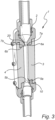
fig. 3 there is shown the embodiment as shown infig. 2 , however here bothelectrode units 3, 4 are put in in place into the PEF chamber. - In
fig. 4 there is also shown an embodiment in line with the ones shown infigs. 1-3 . In this case, a gap distance GE between theopposite electrode units 3, 4 in the PEF chamber and the length LE of the electrodes are also depicted. Moreover, also afirst tube distance 11 arranged before theopposite electrode units 3, 4 in the intended flow direction is also depicted. Furthermore, and in line with this, asecond tube distance 21, which is the tube diameter subsequent to the electrodes, is also shown infig. 4 .
Claims (7)
- PEF (pulsed electric field) chamber (1) intended for treating a flow with electric field pulses, said PEF chamber comprising a PEF treatment tube (2) and opposite electrode units (3, 4), wherein the opposite electrodes units (3, 4) are two flat parallel electrode units (3, 4) which expose two rectangular surfaces and are arranged so that a pumpable material to be treated may flow between the opposite electrodes units (3, 4), characterized in that each one of said opposite electrode units (3, 4) has one flow receiving end (5a, 5b) and one flow exit end (6a, 6b) where the flow to be treated exits between the flow exit ends (6a, 6b) of each opposite electrode units (3, 4), wherein the PEF treatment tube (2) comprises exit flow portions (7a, 7b) arranged subsequent to the flow exit ends (6a, 6b) of the electrode units (3, 4) in the intended flow direction, wherein the exit flow portions (7a, 7b) are part of the isolating material arranged subsequent to the electrode units (3, 4), said exit flow portions (7a, 7b) not being part of the electrode units (3, 4) but functioning as an extension of the opposite electrode units (3, 4) in the intended flow direction, wherein the opposite electrode units (3, 4) are longitudinal, wherein the flow receiving ends (5a, 5b) are rounded in an intended flow direction into the PEF treatment tube (2), wherein the exit flow portions (7a, 7b) are rounded in an intended flow direction, wherein the electrode units (3, 4) are arranged in the PEF treatment tube (2) to provide a first geometrical narrowing (10) of the cross sectional area of the PEF treatment tube (2) at the flow receiving ends (5a, 5b) of the opposite electrodes units (3, 4), and wherein the exit flow portions (7a, 7b) of the PEF treatment tube (2) are arranged to provide a second geometrical narrowing (20) of the cross sectional area of the PEF treatment tube (2) subsequent to the flow exit ends (6a, 6b) of the opposite electrodes units (3, 4), both geometrical narrowings (10, 20) being arranged so that the cross sectional area of the PEF treatment tube (2) is lowered in the geometrical narrowing when compared with a point before in the intended flow direction.
- PEF chamber (1) according to claim 1, wherein each electrode unit (3, 4) is insertable into matching grooves of the PEF treatment tube (2) of the PEF chamber (2).
- PEF chamber (1) according to any of the preceding claims, wherein a relationship of a gap distance (GE) between the opposite electrode units (3, 4) in the PEF chamber (2) to a length (LE) of each electrode unit (3, 4) has a LE/GE ratio of at least 3, preferably at least 6, more preferably at least 8, most preferably at least 10, and/or wherein a length (LE) of each electrode unit (3, 4) is at least 30 mm, preferably in a range of 30 - 600 mm, more preferably in a range of 30 - 300 mm, more preferably in a range of 30 - 200 mm, and wherein a gap distance (GE) between the opposite electrode units (3, 4) in the PEF chamber (2) is at least 3 mm, preferably in a range of 3 - 45 mm, and/or wherein a width (WE) of each electrode unit (3, 4) is at least 3 mm, preferably in the range of 3 - 45 mm, and/or wherein a relationship of a gap distance (GE) between the opposite electrode units (3, 4) in the PEF chamber (2), a length (LE) of each electrode unit (3, 4) and a width (WE) of each electrode unit (3, 4) in the form of GE:WE:LE is in a ratio of from 3:3:20 mm to 45:40:200 mm.
- PEF chamber (1) according to any of claims 1-3, wherein the first geometrical narrowing (10) is arranged as a gap distance (GE) between the opposite electrode units (3, 4), which (GE) is in the range of 40 - 80%, preferably in the range of 45 - 64%, of a first tube distance (11) arranged just before the opposite electrode units (3, 4) in the intended flow direction, wherein the first tube distance (11) thus is the distance between the sides of the isolating material tube just before the opposite electrode units (3, 4).
- PEF chamber (1) according to any of claims 1-4, wherein the second geometrical narrowing (20) is arranged with a second tube distance (21) being the distance between the sides of the isolating material tube just subsequent to the opposite electrode units (3, 4), which is in the range of 65 - 95%, preferably in the range of 70 - 80%, of a gap distance (GE) between the opposite electrode units (3, 4).
- PEF chamber (1) according to any of the preceding claims, wherein the PEF treatment tube (2) comprises a turbulence unit, preferably a helix unit, arranged before the flow receiving ends (5a, 5b) of the electrode units (3, 4).
- PEF chamber (1) according to any of the preceding claims, wherein a splitter is arranged at the end of a treatment volume of the PEF treatment tube (2).
Applications Claiming Priority (2)
| Application Number | Priority Date | Filing Date | Title |
|---|---|---|---|
| SE1951028 | 2019-09-11 | ||
| PCT/SE2020/050853 WO2021049997A1 (en) | 2019-09-11 | 2020-09-11 | Pulsed electric field chamber |
Publications (4)
| Publication Number | Publication Date |
|---|---|
| EP4028155A1 EP4028155A1 (en) | 2022-07-20 |
| EP4028155A4 EP4028155A4 (en) | 2023-08-23 |
| EP4028155C0 EP4028155C0 (en) | 2025-05-14 |
| EP4028155B1 true EP4028155B1 (en) | 2025-05-14 |
Family
ID=72934539
Family Applications (1)
| Application Number | Title | Priority Date | Filing Date |
|---|---|---|---|
| EP20862456.9A Active EP4028155B1 (en) | 2019-09-11 | 2020-09-11 | Pulsed electric field chamber |
Country Status (6)
| Country | Link |
|---|---|
| US (1) | US12245624B2 (en) |
| EP (1) | EP4028155B1 (en) |
| CN (2) | CN211770461U (en) |
| ES (1) | ES3038147T3 (en) |
| PL (1) | PL4028155T3 (en) |
| WO (1) | WO2021049997A1 (en) |
Families Citing this family (3)
| Publication number | Priority date | Publication date | Assignee | Title |
|---|---|---|---|---|
| CN211770461U (en) * | 2019-09-11 | 2020-10-27 | Arc阿罗马珀尔公司 | Pulsed electric field chamber |
| DE102020209334A1 (en) * | 2020-07-23 | 2022-01-27 | DIL Deutsches Institut für Lebensmitteltechnik e.V. | Compact system for pulsed electric fields in a treatment cell |
| KR102808325B1 (en) * | 2022-06-15 | 2025-05-14 | 이동후 | high voltage pulsed electric field treatment apparatus |
Citations (1)
| Publication number | Priority date | Publication date | Assignee | Title |
|---|---|---|---|---|
| CN101502304B (en) * | 2009-03-12 | 2011-09-21 | 浙江大学 | High-voltage pulse electric field processing chamber for continuous liquid foodstuffs sterilization |
Family Cites Families (24)
| Publication number | Priority date | Publication date | Assignee | Title |
|---|---|---|---|---|
| EP0594566B1 (en) * | 1989-06-12 | 1999-09-01 | Purepulse Technologies, Inc. | High pulsed voltage systems for extending the shelf life of pumpable food products |
| US5662031A (en) * | 1994-12-23 | 1997-09-02 | Washington State University Research Foundation, Inc. | Continuous flow electrical treatment of flowable food products |
| US5549041A (en) | 1995-03-02 | 1996-08-27 | Washington State University Research Foundation | Batch mode food treatment using pulsed electric fields |
| US5690978A (en) * | 1996-09-30 | 1997-11-25 | Ohio State University | High voltage pulsed electric field treatment chambers for the preservation of liquid food products |
| NL1010529C2 (en) * | 1998-11-11 | 2000-05-15 | Inst Voor Agrotech Onderzoek | Integrated modular construction of a pulsed electrical field system. |
| NL1014266C2 (en) | 2000-02-02 | 2001-08-03 | Stork Food & Dairy Systems Bv | Treatment device and method for making pumpable food products more sustainable in a pulsating electric field. |
| US20040029240A1 (en) * | 2002-05-13 | 2004-02-12 | Acker Jesse L. | Dynamic electroporation apparatus and method |
| DE10349504A1 (en) * | 2003-10-23 | 2005-05-25 | Bayer Technology Services Gmbh | Process for the preparation of isocyanates in the gas phase |
| DE102004013762B4 (en) | 2004-03-20 | 2006-08-03 | Forschungszentrum Karlsruhe Gmbh | Process for better and gentle release of valuable ingredients from grapes and a must obtained from them |
| EP2941968A1 (en) | 2005-05-12 | 2015-11-11 | Estrella Maarud Holding AS | Device for electroporation of potatoes and potato products |
| JP4719184B2 (en) * | 2007-06-01 | 2011-07-06 | 株式会社サイアン | Atmospheric pressure plasma generator and work processing apparatus using the same |
| DE102008024065A1 (en) | 2008-05-17 | 2009-11-19 | Forschungszentrum Karlsruhe Gmbh | Device and method for pressure-controlled and pressure-controlled, electroporative treatment of biological plant process material |
| JP2011072905A (en) | 2009-09-30 | 2011-04-14 | Sekisui Chem Co Ltd | Water treatment system |
| NL2003853C2 (en) * | 2009-11-23 | 2011-05-24 | Sonder Food Systems B V | DEVICE FOR PASTEURIZING A MASS OF FOODSTUFF. |
| GB2487796A (en) | 2011-02-07 | 2012-08-08 | Cordon Ltd | Pulsed electric field treatment using boron doped diamond electrodes |
| JP5654946B2 (en) * | 2011-05-11 | 2015-01-14 | 積水化学工業株式会社 | Water treatment equipment |
| NL2009466C2 (en) | 2012-09-14 | 2014-03-18 | Zwanenberg Food Group B V | DEVICE FOR PASTEURIZING A MASS OF FOODSTUFF. |
| WO2015089112A1 (en) * | 2013-12-10 | 2015-06-18 | University Of Hawaii | Method of supercooling perishable materials |
| WO2017184066A1 (en) | 2015-04-21 | 2017-10-26 | Arc Aroma Pure Ab | Pef chamber |
| KR20180016991A (en) | 2015-04-21 | 2018-02-20 | 에이알씨 아로마 퓨어 에이비 | Chamber for generating pulse field |
| JP6587159B2 (en) | 2017-06-26 | 2019-10-09 | パナソニックIpマネジメント株式会社 | Liquid processing equipment |
| DE102018202369A1 (en) | 2018-02-15 | 2019-08-22 | Deutsches Institut Für Lebensmitteltechnik E.V. | Flow cell for the treatment of liquids |
| CN109663556B (en) * | 2019-01-27 | 2019-12-31 | 浙江大学 | Reaction device and method for activation of carbon dioxide by disturbance-enhanced dielectric barrier discharge |
| CN211770461U (en) * | 2019-09-11 | 2020-10-27 | Arc阿罗马珀尔公司 | Pulsed electric field chamber |
-
2019
- 2019-10-23 CN CN201921783166.XU patent/CN211770461U/en active Active
-
2020
- 2020-09-11 WO PCT/SE2020/050853 patent/WO2021049997A1/en not_active Ceased
- 2020-09-11 US US17/642,109 patent/US12245624B2/en active Active
- 2020-09-11 ES ES20862456T patent/ES3038147T3/en active Active
- 2020-09-11 CN CN202080064362.0A patent/CN114728259B/en active Active
- 2020-09-11 PL PL20862456.9T patent/PL4028155T3/en unknown
- 2020-09-11 EP EP20862456.9A patent/EP4028155B1/en active Active
Patent Citations (1)
| Publication number | Priority date | Publication date | Assignee | Title |
|---|---|---|---|---|
| CN101502304B (en) * | 2009-03-12 | 2011-09-21 | 浙江大学 | High-voltage pulse electric field processing chamber for continuous liquid foodstuffs sterilization |
Also Published As
| Publication number | Publication date |
|---|---|
| PL4028155T3 (en) | 2025-11-12 |
| CN114728259B (en) | 2024-03-12 |
| CN114728259A (en) | 2022-07-08 |
| WO2021049997A1 (en) | 2021-03-18 |
| ES3038147T3 (en) | 2025-10-09 |
| EP4028155C0 (en) | 2025-05-14 |
| EP4028155A1 (en) | 2022-07-20 |
| US20220361533A1 (en) | 2022-11-17 |
| CN211770461U (en) | 2020-10-27 |
| EP4028155A4 (en) | 2023-08-23 |
| US12245624B2 (en) | 2025-03-11 |
Similar Documents
| Publication | Publication Date | Title |
|---|---|---|
| US12245624B2 (en) | Pulsed electric field chamber | |
| Huang et al. | Designs of pulsed electric fields treatment chambers for liquid foods pasteurization process: A review | |
| US9034194B2 (en) | Apparatus for treating a fluid with microwave radiation | |
| TW409036B (en) | Uniform product flow in a high-electric-field treatment cell | |
| US6110423A (en) | High-strength-electric-field pumpable-food-product treatment in a serial-electrode treatment cell | |
| US20180116256A1 (en) | Chamber for pulsed electric field generation | |
| CN104171767A (en) | High-voltage pulsed electric field sterilizing system coaxial processing chamber with adjustable runner shape | |
| Yan et al. | Optimization of co-linear-type pulsed electric field treatment chamber for milk pasteurization | |
| US11882856B2 (en) | System and method for continuous thermal treatment of a flowable product | |
| EP2334341B1 (en) | Resonance chamber, especially for an apparatus for pasteurization of liquid products | |
| EP1912512B1 (en) | Apparatus for applying oscillating electromagnetic fields, particularly for treating liquid, pasty, semi-solid or granular products, and method of use of such apparatus and system incorporating same | |
| CN102415599A (en) | Common-field processing chamber of high-voltage pulse electric field sterilization system based on coupling field structure optimization | |
| WO2017184066A1 (en) | Pef chamber | |
| AU2013316183A1 (en) | Device and method for providing a high voltage pulsed electric field to a fluid | |
| JP6030040B2 (en) | Continuous energization heating device for fluid food materials | |
| US20110052162A1 (en) | Apparatus and method for heating a product stream | |
| Ghnimi et al. | Tubular and fluid jet units | |
| Kempkes et al. | Scaleup of PEF systems for food and waste streams | |
| Gaudreau et al. | Scaleup of PEF systems for food and waste streams | |
| CN204180838U (en) | The high-pressure pulse electric sterilization system coaxial process chamber that a kind of flow channel shape is adjustable | |
| CN112357989B (en) | Fluid continuous heating device | |
| Huang et al. | Numerical Simulation Study of a Continuous Coaxial PEF Treatment Chamber | |
| Boyko et al. | Working chamber for processing foodstuffs by a complex action of strong pulsed electric fields | |
| Kempkes et al. | PEF systems for food and waste streams | |
| PL212906B1 (en) | Dvice heating flowing liquid |
Legal Events
| Date | Code | Title | Description |
|---|---|---|---|
| STAA | Information on the status of an ep patent application or granted ep patent |
Free format text: STATUS: THE INTERNATIONAL PUBLICATION HAS BEEN MADE |
|
| PUAI | Public reference made under article 153(3) epc to a published international application that has entered the european phase |
Free format text: ORIGINAL CODE: 0009012 |
|
| STAA | Information on the status of an ep patent application or granted ep patent |
Free format text: STATUS: REQUEST FOR EXAMINATION WAS MADE |
|
| 17P | Request for examination filed |
Effective date: 20220407 |
|
| AK | Designated contracting states |
Kind code of ref document: A1 Designated state(s): AL AT BE BG CH CY CZ DE DK EE ES FI FR GB GR HR HU IE IS IT LI LT LU LV MC MK MT NL NO PL PT RO RS SE SI SK SM TR |
|
| DAV | Request for validation of the european patent (deleted) | ||
| DAX | Request for extension of the european patent (deleted) | ||
| REG | Reference to a national code |
Ref country code: DE Ref legal event code: R079 Ipc: A61L0002030000 Ref country code: DE Ref legal event code: R079 Ref document number: 602020051392 Country of ref document: DE Free format text: PREVIOUS MAIN CLASS: B01J0019080000 Ipc: A61L0002030000 |
|
| A4 | Supplementary search report drawn up and despatched |
Effective date: 20230720 |
|
| RIC1 | Information provided on ipc code assigned before grant |
Ipc: C02F 1/46 20060101ALI20230714BHEP Ipc: B01J 19/08 20060101ALI20230714BHEP Ipc: A23L 3/32 20060101ALI20230714BHEP Ipc: A61L 2/03 20060101AFI20230714BHEP |
|
| STAA | Information on the status of an ep patent application or granted ep patent |
Free format text: STATUS: EXAMINATION IS IN PROGRESS |
|
| 17Q | First examination report despatched |
Effective date: 20240712 |
|
| REG | Reference to a national code |
Ref country code: DE Ref legal event code: R079 Ipc: A23L0005300000 Ref country code: DE Ref legal event code: R079 Ref document number: 602020051392 Country of ref document: DE Free format text: PREVIOUS MAIN CLASS: A61L0002030000 Ipc: A23L0005300000 |
|
| GRAP | Despatch of communication of intention to grant a patent |
Free format text: ORIGINAL CODE: EPIDOSNIGR1 |
|
| STAA | Information on the status of an ep patent application or granted ep patent |
Free format text: STATUS: GRANT OF PATENT IS INTENDED |
|
| RIC1 | Information provided on ipc code assigned before grant |
Ipc: A23L 5/30 20160101AFI20250113BHEP |
|
| INTG | Intention to grant announced |
Effective date: 20250207 |
|
| GRAS | Grant fee paid |
Free format text: ORIGINAL CODE: EPIDOSNIGR3 |
|
| GRAA | (expected) grant |
Free format text: ORIGINAL CODE: 0009210 |
|
| STAA | Information on the status of an ep patent application or granted ep patent |
Free format text: STATUS: THE PATENT HAS BEEN GRANTED |
|
| AK | Designated contracting states |
Kind code of ref document: B1 Designated state(s): AL AT BE BG CH CY CZ DE DK EE ES FI FR GB GR HR HU IE IS IT LI LT LU LV MC MK MT NL NO PL PT RO RS SE SI SK SM TR |
|
| REG | Reference to a national code |
Ref country code: GB Ref legal event code: FG4D |
|
| REG | Reference to a national code |
Ref country code: CH Ref legal event code: EP |
|
| REG | Reference to a national code |
Ref country code: DE Ref legal event code: R096 Ref document number: 602020051392 Country of ref document: DE |
|
| REG | Reference to a national code |
Ref country code: IE Ref legal event code: FG4D |
|
| RAP4 | Party data changed (patent owner data changed or rights of a patent transferred) |
Owner name: OPTICEPT TECHNOLOGIES AB |
|
| U01 | Request for unitary effect filed |
Effective date: 20250613 |
|
| U07 | Unitary effect registered |
Designated state(s): AT BE BG DE DK EE FI FR IT LT LU LV MT NL PT RO SE SI Effective date: 20250620 |
|
| U20 | Renewal fee for the european patent with unitary effect paid |
Year of fee payment: 6 Effective date: 20250815 |
|
| REG | Reference to a national code |
Ref country code: ES Ref legal event code: FG2A Ref document number: 3038147 Country of ref document: ES Kind code of ref document: T3 Effective date: 20251009 |
|
| PG25 | Lapsed in a contracting state [announced via postgrant information from national office to epo] |
Ref country code: NO Free format text: LAPSE BECAUSE OF FAILURE TO SUBMIT A TRANSLATION OF THE DESCRIPTION OR TO PAY THE FEE WITHIN THE PRESCRIBED TIME-LIMIT Effective date: 20250814 |
|
| PGFP | Annual fee paid to national office [announced via postgrant information from national office to epo] |
Ref country code: GR Payment date: 20250827 Year of fee payment: 6 |
|
| PGFP | Annual fee paid to national office [announced via postgrant information from national office to epo] |
Ref country code: GB Payment date: 20250813 Year of fee payment: 6 |
|
| PG25 | Lapsed in a contracting state [announced via postgrant information from national office to epo] |
Ref country code: HR Free format text: LAPSE BECAUSE OF FAILURE TO SUBMIT A TRANSLATION OF THE DESCRIPTION OR TO PAY THE FEE WITHIN THE PRESCRIBED TIME-LIMIT Effective date: 20250514 |
|
| PG25 | Lapsed in a contracting state [announced via postgrant information from national office to epo] |
Ref country code: RS Free format text: LAPSE BECAUSE OF FAILURE TO SUBMIT A TRANSLATION OF THE DESCRIPTION OR TO PAY THE FEE WITHIN THE PRESCRIBED TIME-LIMIT Effective date: 20250814 |
|
| PG25 | Lapsed in a contracting state [announced via postgrant information from national office to epo] |
Ref country code: IS Free format text: LAPSE BECAUSE OF FAILURE TO SUBMIT A TRANSLATION OF THE DESCRIPTION OR TO PAY THE FEE WITHIN THE PRESCRIBED TIME-LIMIT Effective date: 20250914 |
|
| REG | Reference to a national code |
Ref country code: GR Ref legal event code: EP Ref document number: 20250401581 Country of ref document: GR Effective date: 20251009 |
|
| PG25 | Lapsed in a contracting state [announced via postgrant information from national office to epo] |
Ref country code: SM Free format text: LAPSE BECAUSE OF FAILURE TO SUBMIT A TRANSLATION OF THE DESCRIPTION OR TO PAY THE FEE WITHIN THE PRESCRIBED TIME-LIMIT Effective date: 20250514 |
|
| PG25 | Lapsed in a contracting state [announced via postgrant information from national office to epo] |
Ref country code: CZ Free format text: LAPSE BECAUSE OF FAILURE TO SUBMIT A TRANSLATION OF THE DESCRIPTION OR TO PAY THE FEE WITHIN THE PRESCRIBED TIME-LIMIT Effective date: 20250514 |
|
| PGFP | Annual fee paid to national office [announced via postgrant information from national office to epo] |
Ref country code: PL Payment date: 20250801 Year of fee payment: 6 |
|
| PG25 | Lapsed in a contracting state [announced via postgrant information from national office to epo] |
Ref country code: SK Free format text: LAPSE BECAUSE OF FAILURE TO SUBMIT A TRANSLATION OF THE DESCRIPTION OR TO PAY THE FEE WITHIN THE PRESCRIBED TIME-LIMIT Effective date: 20250514 |
|
| PGFP | Annual fee paid to national office [announced via postgrant information from national office to epo] |
Ref country code: ES Payment date: 20251001 Year of fee payment: 6 |
|
| PLBE | No opposition filed within time limit |
Free format text: ORIGINAL CODE: 0009261 |
|
| STAA | Information on the status of an ep patent application or granted ep patent |
Free format text: STATUS: NO OPPOSITION FILED WITHIN TIME LIMIT |
|
| REG | Reference to a national code |
Ref country code: CH Ref legal event code: L10 Free format text: ST27 STATUS EVENT CODE: U-0-0-L10-L00 (AS PROVIDED BY THE NATIONAL OFFICE) Effective date: 20260325 |
|
| 26N | No opposition filed |
Effective date: 20260217 |
|
| REG | Reference to a national code |
Ref country code: CH Ref legal event code: H13 Free format text: ST27 STATUS EVENT CODE: U-0-0-H10-H13 (AS PROVIDED BY THE NATIONAL OFFICE) Effective date: 20260425 |