EP4027872B1 - System zum nichtinvasiven messen von blutvolumenschwingungen im schädel eines menschen - Google Patents
System zum nichtinvasiven messen von blutvolumenschwingungen im schädel eines menschen Download PDFInfo
- Publication number
- EP4027872B1 EP4027872B1 EP20862130.0A EP20862130A EP4027872B1 EP 4027872 B1 EP4027872 B1 EP 4027872B1 EP 20862130 A EP20862130 A EP 20862130A EP 4027872 B1 EP4027872 B1 EP 4027872B1
- Authority
- EP
- European Patent Office
- Prior art keywords
- output signals
- cranium
- cranial
- superficial
- light source
- Prior art date
- Legal status (The legal status is an assumption and is not a legal conclusion. Google has not performed a legal analysis and makes no representation as to the accuracy of the status listed.)
- Active
Links
Images


Classifications
-
- A—HUMAN NECESSITIES
- A61—MEDICAL OR VETERINARY SCIENCE; HYGIENE
- A61B—DIAGNOSIS; SURGERY; IDENTIFICATION
- A61B5/00—Measuring for diagnostic purposes; Identification of persons
- A61B5/03—Measuring fluid pressure within the body other than blood pressure, e.g. cerebral pressure ; Measuring pressure in body tissues or organs
- A61B5/031—Intracranial pressure
-
- A—HUMAN NECESSITIES
- A61—MEDICAL OR VETERINARY SCIENCE; HYGIENE
- A61B—DIAGNOSIS; SURGERY; IDENTIFICATION
- A61B5/00—Measuring for diagnostic purposes; Identification of persons
- A61B5/0059—Measuring for diagnostic purposes; Identification of persons using light, e.g. diagnosis by transillumination, diascopy, fluorescence
- A61B5/0082—Measuring for diagnostic purposes; Identification of persons using light, e.g. diagnosis by transillumination, diascopy, fluorescence adapted for particular medical purposes
-
- A—HUMAN NECESSITIES
- A61—MEDICAL OR VETERINARY SCIENCE; HYGIENE
- A61B—DIAGNOSIS; SURGERY; IDENTIFICATION
- A61B5/00—Measuring for diagnostic purposes; Identification of persons
- A61B5/68—Arrangements of detecting, measuring or recording means, e.g. sensors, in relation to patient
- A61B5/6801—Arrangements of detecting, measuring or recording means, e.g. sensors, in relation to patient specially adapted to be attached to or worn on the body surface
- A61B5/6813—Specially adapted to be attached to a specific body part
- A61B5/6814—Head
- A61B5/6815—Ear
-
- A—HUMAN NECESSITIES
- A61—MEDICAL OR VETERINARY SCIENCE; HYGIENE
- A61B—DIAGNOSIS; SURGERY; IDENTIFICATION
- A61B5/00—Measuring for diagnostic purposes; Identification of persons
- A61B5/68—Arrangements of detecting, measuring or recording means, e.g. sensors, in relation to patient
- A61B5/6801—Arrangements of detecting, measuring or recording means, e.g. sensors, in relation to patient specially adapted to be attached to or worn on the body surface
- A61B5/6813—Specially adapted to be attached to a specific body part
- A61B5/6823—Trunk, e.g., chest, back, abdomen, hip
-
- A—HUMAN NECESSITIES
- A61—MEDICAL OR VETERINARY SCIENCE; HYGIENE
- A61B—DIAGNOSIS; SURGERY; IDENTIFICATION
- A61B5/00—Measuring for diagnostic purposes; Identification of persons
- A61B5/68—Arrangements of detecting, measuring or recording means, e.g. sensors, in relation to patient
- A61B5/6801—Arrangements of detecting, measuring or recording means, e.g. sensors, in relation to patient specially adapted to be attached to or worn on the body surface
- A61B5/6813—Specially adapted to be attached to a specific body part
- A61B5/6824—Arm or wrist
-
- A—HUMAN NECESSITIES
- A61—MEDICAL OR VETERINARY SCIENCE; HYGIENE
- A61B—DIAGNOSIS; SURGERY; IDENTIFICATION
- A61B5/00—Measuring for diagnostic purposes; Identification of persons
- A61B5/68—Arrangements of detecting, measuring or recording means, e.g. sensors, in relation to patient
- A61B5/6801—Arrangements of detecting, measuring or recording means, e.g. sensors, in relation to patient specially adapted to be attached to or worn on the body surface
- A61B5/6813—Specially adapted to be attached to a specific body part
- A61B5/6825—Hand
- A61B5/6826—Finger
-
- A—HUMAN NECESSITIES
- A61—MEDICAL OR VETERINARY SCIENCE; HYGIENE
- A61B—DIAGNOSIS; SURGERY; IDENTIFICATION
- A61B5/00—Measuring for diagnostic purposes; Identification of persons
- A61B5/68—Arrangements of detecting, measuring or recording means, e.g. sensors, in relation to patient
- A61B5/6801—Arrangements of detecting, measuring or recording means, e.g. sensors, in relation to patient specially adapted to be attached to or worn on the body surface
- A61B5/6813—Specially adapted to be attached to a specific body part
- A61B5/6828—Leg
-
- A—HUMAN NECESSITIES
- A61—MEDICAL OR VETERINARY SCIENCE; HYGIENE
- A61B—DIAGNOSIS; SURGERY; IDENTIFICATION
- A61B5/00—Measuring for diagnostic purposes; Identification of persons
- A61B5/68—Arrangements of detecting, measuring or recording means, e.g. sensors, in relation to patient
- A61B5/6801—Arrangements of detecting, measuring or recording means, e.g. sensors, in relation to patient specially adapted to be attached to or worn on the body surface
- A61B5/6813—Specially adapted to be attached to a specific body part
- A61B5/6829—Foot or ankle
-
- A—HUMAN NECESSITIES
- A61—MEDICAL OR VETERINARY SCIENCE; HYGIENE
- A61B—DIAGNOSIS; SURGERY; IDENTIFICATION
- A61B5/00—Measuring for diagnostic purposes; Identification of persons
- A61B5/02—Detecting, measuring or recording for evaluating the cardiovascular system, e.g. pulse, heart rate, blood pressure or blood flow
- A61B5/021—Measuring pressure in heart or blood vessels
- A61B5/02108—Measuring pressure in heart or blood vessels from analysis of pulse wave characteristics
- A61B5/02125—Measuring pressure in heart or blood vessels from analysis of pulse wave characteristics of pulse wave propagation time
Definitions
- This invention relates to a system and method for non-invasively measuring blood volume oscillations inside the cranium of a human subject and using the measured oscillations to non-invasively determine intracranial pressure (IPC).
- IPC intracranial pressure
- NIR near-infrared
- Conventional optical sensing systems have been used to monitor both blood volume oscillations and blood oxygen content by using one or more light sources and detector placed on the skin. All such measurements that seek to obtain information from within the cranium are subject to confounding of the reflected (or scattered) return light signal to the detector by the necessity of the light to transit the superficial region or superficial space above the cranium,.
- fNIRS near infrared spectroscopy
- U.S. Pub. No. 2019/0269853 discloses a system that determines fluid administration based on fluid responsiveness to regional oxygen saturation of a subject.
- the subject may receive the fluid responsiveness and regional oxygen saturation from an external source and may be determined one or both based on the received physiological signals
- U.S. Pub. No. 2019/0021646 discloses a system for non-invasively measuring oxygen wavelength dependent changes in optical absorptions of brain tissue.
- the brain tissue is trans-cranially illuminated by light sources in low-absorption spectrum windows for the tissue in the visible or near infrared parts of the spectrum.
- 2012/0108927 discloses a method and apparatus for non-invasively determining blood oxygenation within a subject tissue that utilizes near infrared spectrophotometric (NIRs) sensor capable of transmitting a light signal into the tissue of a subject and sensing the light signal once it has passed through the tissue.
- NIRs near infrared spectrophotometric
- WO 2019/040849 discloses an optical probe including three optical elements including at least one light source and at least one light detector. The three optical elements are positioned in a triangular configuration. A light shroud is disposed radially around the exposed distal and portions of the optical fibers coupled to the light source.
- Weerakkody et. al. discloses slow vasogenic fluctuation of intercranial pressure and cerebral using near infrared spectroscopy.
- PbB. No. 2018/0110449 teaches an oxygen saturation measuring sensor which includes a pad attachable to the human body, a plurality of light sources arranged on the pad and irradiate near-infrared light. A plurality of light receiving elements arrange on the pad to be adjacent in a separated stage and correspond to one of the pluralities of light sources with reference to a common center.
- U.S. Pub No. 2015/0018697 disclosed a system with a first sensor placed proximate to a perfusion field of an artery receiving blood emanating from the cranial cavity and monitors pulsation of the artery receiving blood emanating from the cranial cavity.
- a second sensor is placed proximate to a perfusion field of an artery which does not receive blood emanating from the cranial cavity.
- the second sensor monitors pulsation of the artery which does not receive blood and emanating from the cranial cavity.
- a third sensor is placed distally from a heart and monitors pulsation of a distal artery.
- a processing subsystem responsive to signal from the first, second and third sensor determines intracranial pressure.
- the apparatus includes at least one light source which transmits light through the biological entity and at least one photodetector for receiving light transmitted through the biological entity
- a signal is generated and response to transmitted or reflected light through the biological entity signal which corresponds to at least one characteristic of the generally unimpeded blood flow through the biological entity.
- U.S. PUB No. 2016/0278643 teaches a signal derived from the brain attribute cortex maybe may be extracted by separating and removing influence of the skin blood flood included in NIRs signals.
- a biphotonic measurement apparatus is used to separate signals simultaneously measured with a plurality of irradiator-detector distances into the brain blood flood-derived signals and skin blood flow-derived signals using SD distance dependency of signal amplitude.
- 2009/0234245 discloses a system for a noninvasive detection of intercranial pressure (ICP) variation in an intracranial compartment of a patient.
- Optical radiation is propagated trans-cranially into the cranial compartment and optical radiation that has migrated through at least a portion of the cranial compartment and back out of the cranium is detected.
- ICP intercranial pressure
- a system for non-invasively measuring blood volume oscillations inside a cranium of a human subject comprising:
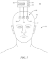
- System 10 for non-invasively measuring blood volume oscillations inside cranium 12 of human subject 14
- System 10 includes first light source 16 adapted to be placed on skin 17 above cranium 12 of human subject 14.
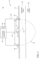
- First light source 16 is configured to emit light 18, Fig. 2 , which penetrates superficial space 20 outside cranium 12.
- System 10 also includes detector 22 adapted to be placed on skin 17 above cranium 12 of human subject 14.
- Detector 22 is spaced from first light source 16 by first predetermined separation, distance d-24, Fig. 2 , that causes detector 22 to detect light 18 which reflects from superficial space 20 outside cranium 12 and output superficial output signals.
- System 10 also includes second light source 30 adapted to be placed on skin 17 above cranium 12.
- Second light source 30 is configured to emit light 32, Fig. 2 , which penetrates through superficial space 20 outside cranium 12 to inside cranium 46.
- Detector 22 is spaced from second light source 30 by second predetermined separation distance, d-34, that causes detector 22 to detect light 32 which reflects from inside cranium 46 and output cranial output signals.
- first light source 16, second light source 20 and detector 22 may be adapted to be placed on forehead 60, Fig. 1 , of cranium 12 as shown.
- System 10, Figs. 1 and 2 also includes processing subsystem 40 coupled to first light source 16, second light source 30, and detector 22 as shown.
- Processing subsystem 40 may be a processor, e.g., processor 42, one or more processors, an application-specific integrated circuit (ASIC), firmware, hardware, and/or software (including firmware, resident software, micro-code, and the like) or a combination of both hardware and software.
- Processing subsystem 40 preferably includes one or more programs stored in a memory, e.g., memory 44, which are configured to be executed by the one or more processors.
- Computer program code for the programs for carrying out the instructions or operation of processing subsystem 40 may be written in any combination of one or more programming languages, including an object-oriented programming language, e.g., C++, Smalltalk, Java, and the like, or conventional procedural programming languages, such as the "C' programming language, Assembly language or similar programming languages.
- object-oriented programming language e.g., C++, Smalltalk, Java, and the like
- conventional procedural programming languages such as the "C' programming language, Assembly language or similar programming languages.
- Processing subsystem 40 is configured to alternately enable first light source 16 to emit light 18 which penetrates superficial space 20 outside cranium 12 and second light source 30 to emit light 32 which penetrates through the superficial space outside the cranium to inside cranium 46 and alternately enable detector 22 to detect light 18 which reflects from superficial space 20 outside the cranium emitted by first light source 16 to generate the superficial output signals and detect light 32 emitted by second light source 30 which reflects from inside cranium 46 to generate the cranial output signals.
- Processing subsystem 40 is responsive to the superficial output signals and the cranial output signals and is further configured to reduce contributions from the superficial space existing in the cranial output signals and generate corrected cranial output signals indicative of blood volume oscillations inside the cranium, Processing subsystem 40 may reduce the superficial contribution in the cranial signal by subtraction of normalized signals, linear regression where the superficial signal is used as a regressor and the unprocessed cranial signal as the regressed, Kalman filtering, other mathematical and statistical techniques known in the art, and physics-based photon propagation models.
- processing by processing subsystem 40 may avoid filtering of frequency components of the signals in the region of about 0.5 Hz to about 2.0 Hz which contains the cardiac signal in order to preserve important wave shape and timing characteristics of the blood volume oscillation in the corrected cranial output signal.
- the correction in the corrected cranial output signals by processing subsystem 40 may be null. As disclosed herein, such uncorrected cranial output signals are still referred to as corrected cranial output signals and the systems and methods discussed below may be utilized but may be less accurate.
- system 10 for non-invasively measured blood volume oscillations inside the cranium and has effectively reduced the contributions in the light detected by detector 22 from inside the cranium which has passed through superficial space 20 due to the blood volume oscillations in the superficial space.
- system 10 non-invasively, accurately, and effectively measures blood volume oscillations inside the cranium of a human subject.
- the measured blood volume oscillations may be used to non-invasively, accurately, and effectively measure ICP, as discussed below.
- first light source 16, Figs. 1 and 2 , second light source 30, and detector 22 may be adapted to be placed above skin 17 above cranium 12 of human subject 14 with first light source 16 located between second light source 30 and detector 22 as shown.
- first light source 16 and/or second light source 30 may include at least one near-infrared (NIR) light source. In other examples, first light source 16 and/or second light source 30 may include at least one light emitting diode (LED).
- NIR near-infrared
- LED light emitting diode
- pulse transit time is the time it takes for a blood pressure pulse to travel from one location of human subject 14 to another location of human subject 14 in the vasculature of a human subject. If the length along the vascular tree between the two locations on human subject 14 is known, then the pulse wave velocity (PWV) can be calculated from one location on human subject 14 to another location of human subject 14 and used to determine ICP inside the cranium of human subject 14, as discussed below,
- a differential pulse transit time may also be defined as the time difference between arrival of the cardiac pulse at one location on human subject 14, e.g., any of the locations shown in Fig. 3 (discussed below), to another location on human subject 14, e.g., any of the locations shown in Fig. 3 , even though the two locations do not lie on same vascular pathway from the heart, 70, shown in Figure 3 .
- system 10 may also include reference sensor 50, Fig. 3 , adapted to be placed on human subject 14, e.g., on any of the locations shown in Fig. 3 , such as an car, a temple, a finger, a hand, a forearm, a wrist, a chest, a back, a leg, a toe, a foot, and the like, of the human subject.
- Reference sensor 30 is coupled to processing subsystem 40, exemplarily indicated at 52.
- Reference sensor 50 is configured to provide reference signals to be used as a time reference for processing subsystem 40 to calculate a differential pulse transit time from one location on human subject 14, e.g., any of the locations shown in Fig. 3 , to the corrected cranial output signals.
- reference sensor 30 may include at least one NIR sensor. In another examples, reference sensor 30 may include at least one electrocardiogram (ECG) sensor, at least one plethysmograph sensor, at least one pressure sensor. or similar type sensors.
- ECG electrocardiogram
- processing subsystem 40 may be configured to calculate a phase shift of the corrected cranial output signals compared to the reference signals and determine ICP of human subject 14 from the phase difference of the corrected cranial output signals compared to the reference signals.
- processing subsystem 40 may calculate a difference or transfer function between the superficial output signals and the corrected cranial output signals and determine ICP from the difference.
- the superficial output signal indicates pulse transit time from the heart along a vascular pathway including the exterior carotid artery and the corrected cranial output signals indicate pulse transit time along a vascular pathway including the interior carotid artery and through the cranium where it is influenced by changes in ICP.
- processing subsystem 40 may calculate a phase shift of the corrected cranial output signals compared to the superficial output signals and determine ICP of human subject 14 from a phase shift of the corrected cranial output signals compared to the superficial output signals.
- processing system 40 may calculate a time delay between the corrected cranial output signals and the superficial output signals and determine intracranial pressure of the human subject from the time delay.
- the major features of the superficial output signals and the corrected cranial output signals may include a peak of a waveform of the superficial output signals and a peak of a waveform of the corrected cranial output signals, a trough of a waveform of the superficial output signals and a trough of a waveform corrected cranial output signals, or similar major features of the superficial output signals and the corrected cranial output signals, as known by those skilled in the art.
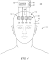
- system 100, Fig. 4 for non-invasively measuring blood volume oscillations inside cranium 12 of human subject 14 includes first sensor 102 adapted to be placed on skin 17 above cranium 12 of human subject 14.
- First sensor 102 includes first light source 104 and first light detector 106.
- First light source 104 is configured to emit light 108, Fig. 5 , which penetrates superficial space 20 outside cranium 12.
- First detector 106 is spaced from first light source 104 by first predetermined separation distance, d-1 10, that causes first detector 106 to detect light 108 which reflects from superficial space 20 outside cranium 12 and output superficial output signals.
- System 100 also includes second sensor 112 adapted to be placed on skin 17 above cranium 12 of human subject 14.
- Second sensor 112 is adapted to be placed proximate to first sensor 102
- Second sensor 112 includes second light source 120 and second detector 122.
- Second light source 120 is configured to emit light 124 which penetrates through superficial space 20 outside cranium 12 to inside cranium 46
- Second detector 122 is preferably placed proximate first detector 106 as shown in Figs. 4 and 5 and is spaced from second light source 120 by second predetermined separation distance, d-126, Fig. 5 , that causes detector 122 to detect light 124 which reflects from inside cranium 146 and output cranial output signals.
- Processing subsystem 40 is coupled to first sensor 102 including first light source 104 and first detector 106 and second sensor 112 including second light source 120 and second detector 122.
- Processing subsystem 40 is configured to alternately enable first light source 104 to emit light 108 which penetrates superficial space 20 outside cranium 12 and second light source 120 to emit light 124 which penetrates through the superficial space outside the cranium to inside cranium 46 and alternately enable first detector 106 to detect light 108 which reflects from superficial space 20 outside cranium 12 and alternately enable second detector 122 to detect light 124 which reflects from inside cranium 46 to generate the superficial output signals and the cranial output signals.
- Processing subsystem 40 is responsive to the superficial output signals and the cranial output signals and is configured to reduce contributions from the superficial space existing in the cranial output signals and generate corrected cranial output signals indicative of blood volume oscillations inside the cranium, similar as discussed above with reference to one or more of Figs. 1-3 .
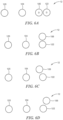
- first sensor 102, Figs. 4 and 5 , and second sensor 112 are adapted to be placed above skin 17 of cranium 12 with first light source 104 preferably located between second light source 120 and first detector 106 and second detector 122, e.g. in a line as shown in a top view in Fig 6A .
- first detector 106 and second detector 122 may be adapted to be placed in a side-by-side configuration from first light source 104 and second light source 120, e.g., as shown in top view Fig 6B , or at an angle to each other, e.g. as shown in Figs. 6C and 6D .
- first sensor 102 and/or second sensor 112 may include at least one NIR sensor.
- first light source 104 and/or second light source 122 may include at least one light emitting diode (LED).
- first sensor 102 and second sensor 112 may be configured to share first detector 106 or second detector 122, e.g. similar as discussed above with reference to Figs. 1-3 .
- System 100 may also include third sensor 50, similar as discussed above with reference to Fig. 3 adapted to be placed on human subject 14 configured to provide reference signals to be used as a time reference for calculating a pulse transit time from one location on the human subject to the cranial output signals, similar as discussed above with reference to one or more of Figs, 1-3 .
- third sensor 50 similar as discussed above with reference to Fig. 3 adapted to be placed on human subject 14 configured to provide reference signals to be used as a time reference for calculating a pulse transit time from one location on the human subject to the cranial output signals, similar as discussed above with reference to one or more of Figs, 1-3 .
- first sensor 102, Figs. 4 and 5 , and second sensor 112 may be adapted to be placed on forehead 60, Fig. 4 , of cranium 12.
- third sensor 30 may be adapted to be placed on any location of human subject 14 as discussed above with reference to Fig. 3 , In one example, third sensor may be adapted to be placed approximately the same distance from heart 70, Fig. 3 , as first sensor 102 and/or second sensor 112.
- Processing subsystem 40 may also be configured to calculate a phase shift of the corrected cranial output signals compared to the reference signals and determine ICP of human subject 14 from the phase shift of the corrected cranial output signals compared to the reference signals.
- processing subsystem 40 may also be configured to calculate a difference or transfer function between the superficial output signals and the corrected cranial output signals and determine ICP from the difference or transfer function.
- processing subsystem 40 may be configured to calculate a phase shift of the corrected cranial output signals compared to the superficial signals and determine ICP of human subject 14 from the phase shift of the corrected cranial output signals compared to the superficial signals.
- processing system 40 may calculate a time delay between the corrected cranial output signals and the superficial output signals and determine intracranial pressure of the human subject from the time delay, similar as discussed above.
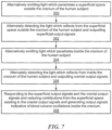
- the method for non-invasively measuring blood volume oscillations inside the cranium of a human subject may include alternately emitting light which penetrates a superficial space outside the cranium, step 300, Fig. 7 .
- the method also includes alternately detecting light which reflects from the superficial space outside the cranium of the human subject and outputting superficial output signals, step 302.
- the method also includes alternately emitting light which penetrates inside the cranium of the human subject, step 304, The method also includes alternately detecting the light which reflects from inside the cranium of the human subject and outputting cranial output signals, step 306, The method also includes responding to the superficial output signals and the cranial output signals and reducing contributions from the superficial space existing in the cranial output signals and generating corrected cranial output signals indicative of blood volume oscillations inside the cranium, step 308, similar as discussed above with reference to one or more of Figs. 1-6 .
- the method may also include providing reference signals to be used as a time reference for calculating a pulse transmit time from one location of a human subject to the corrected cranial output signals.
- the method may include calculating a phase shift in the corrected cranial output signals compared to the reference signals and determining intracranial pressure of the human subject from the phase shift of the corrected cranial output signals compared to the reference signals.
- the method may include calculating a difference or transfer function between the superficial output signals and corrected cranial output signals and determining intracranial pressure from the difference or transfer function.
- the method may include calculating a phase shift of the corrected cranial output signals compared to the superficial output signals and determining intracranial pressure of the human subject from the phase shift of the corrected cranial output signals compared to the superficial output signals.
- the method may include calculating a magnitude of the superficial output signals and the corrected cranial output signals and determining intracranial pressure of the human subject from a difference in magnitude of the superficial output signals and the corrected cranial output signals.
- the method may include calculating a time delay between the corrected cranial output signals and the superficial output signals and determining intracranial pressure of the human subject from the time delay.
- system 10, 100, and the method thereof discussed above with reference to one or more of Figs. 1-8 may utilize one or more or multiple light sources and one or more or multiple detectors adapted to be placed on the forehead of the human subject provided the combination of at least one light source and one detector are separated by a separation distance that causes the detector to receive light that reflects from the superficial space above the cranium of the human subject to provide the superficial signals and at least one light source and one detector are separated by a separation distance that causes the detector to receive light that reflects from the cranium of the human subject to provide cranial output signals.
- one or more light sources and one or more detectors may be employed there may be multiple light source/detector pairings that provide the desired signals but from different positions over the cranium, which may be desirable to provide a diversity of locations where the measurement is made in order to further confirm the measurement or improve its accuracy or reliability by combining measurements from multiple locations, for example by averaging the measurements.
- System 10 and the method thereof and/or system 100 and the method thereof discussed above with reference to one or more of Figs. 1-7 may determine ICP similar as 17 disclosed in applicant's pending Published patent applications, U.S. Pub. No. 2016/0192849 published July 7, 2016 and U.S. Pub. No. 2016/0174858 published June 23, 2016 and applicant's U.S. Patent Nos.
- ICP may be determined by determining the magnitude and phase of the spectral components of the first (superficial output signals), second (corrected cranial output signals), and third signals (reference signals) from each of first sensor, second sensor, and third sensor and comparing the magnitude or the phase of the spectral components of first sensor to the magnitude or the phase of the spectral components of third sensor and the magnitude or the phase of the spectral components of second sensor to the magnitude or the phase of the spectral components of third sensor and combining the compared values.
- ICP may also be determined by combining the signals from the first sensor with the signals from the second sensor and combining the result with the signals from the third sensor. ICP may also be determined determining a first time lag between a peak of a signal from the first output signals (superficial output signals) to a peak of a signal from the third output signals (reference output signals) and a second time lag between a peak of a signal from the second output signals (corrected cranial output signals) to a peak of a signal from the third output signals (reference signals) and calculating the intracranial pressure based on the difference between the first time lag and the second time lag.
- ICP may also be determined by determining a time lag between a peak of a signal from the first output signals (superficial output signals) and a peak of signal from the second output signals (corrected cranial output signals) and calculating the intracranial pressure based on the time lag.
- ICP may also be determined by determining a first lag time between a peak of a signal from the first output signals (superficial output signals) to a peak of a signal from the third output signals (reference signals), a second time lag between a peak of a signal from the second output signals (corrected cranial output signals) to a peak of a signal from the third output signals (reference signals), and a third time lag between the peak of a signal from the first output signals (superficial output signals) to a peak of a signal from the second output signals (corrected cranial output signals) and calculating the intracranial pressure based on differences of the first, second, and third time lags.
- Processing subsystem 40 shown in Figs. 1-7 may also include a feature extractor as disclosed in the '849 Patent Application configured to calculate one or more features from one or more of the first output signals (superficial output signals), the second output signals (corrected cranial output signals), and/or the third output signals (reference signals) and output the one or more features to an artificial neural network configured to calculate the intracranial pressure based on the one or more features.
- the feature extractor may be configured to calculate the one or more features individually from one or more of the first output signals (superficial output signals), the second output signals (corrected cranial output signals), and/or the third output signals (reference signals).
- the one or more features include one or more of: an amplitude of a largest peak in one of the first output signals (superficial output signals), the second output signals (corrected cranial output signals) and/or the third output signals (reference signals), a time from a beginning of a data acquisition cycle to a time of a maximum peak of one of the first output signals (superficial output signals), the second output signals (corrected cranial output signals) and/or the third output signals (reference signals), and a time between two different peaks of one of the first output signals (superficial output signals), the second output signals (corrected cranial output signals) and/or the third output signals (reference signals).
- the feature extractor may be configured to calculate the one or more features from a combination of signals of the first output signals (superficial output signals), the second output signals (corrected cranial output signals) and/or the third output signals (reference signals).
- the one or more features include one or more of: an amplitude of a largest peak in one of the first output signals (superficial output signals), the second output signals (corrected cranial output signals) and/or the third output signals (reference signals), a time from a beginning of a data acquisition cycle to a time of a maximum peak of one of the first output signals (superficial output signals), the second output signals (corrected cranial output signals) and/or the third output signals (reference signals), and a time between two different peaks of one of the first output signals (superficial output signals), the second output signals (corrected cranial output signals) and/or the third output signals (reference signals).
- System 10, 100, and the method thereof shown in one or more of Figs. 1-7 may also include the artificial neural network as disclosed in the '849 Published Patent Application, which may be configured to combine the one or more features in a nonlinear fashion based on various weights in the structure of the artificial neural network to provide the intracranial pressure.
- System 10, 100 and the method thereof may also calculate the phase shift of different frequencies included in the first output signals (superficial output signals) and the second output signals (corrected cranial output signals) and determine intracranial pressure of the human subject from the phase shift at the different frequencies of the first output signals (superficial output signals) and the second output signals (corrected cranial output signals).
- System 10, 100 may also calculate a difference between the first output signals (superficial output signals) and second output signals (corrected cranial output signals) and determine the intracranial pressure from the difference.
- code portions are provided which can be executed on one or more processors, a computing device, a computer, a smart device, or similar type device to carry out the primary steps and/or functions of the system and method for non-invasively measuring blood volume oscillations inside a cranium of a human subject discussed above with reference to one or more of Figs. 1-7 .
- Other equivalent algorithms and code can be designed by a software engineer and/or programmer skilled in the art using the information provided herein:
- the exemplary code above executed by processing subsystem 40, of system 10, 100 and method thereof for non-invasively measuring blood volume oscillations inside a cranium of a human subject discussed above with reference to one or more of Figs. 1-7 preferably includes acquiring NIR signals, step 350, Fig. 8 , data conditioning, step 352, isolating frequency components of interest in NIR signals, step 354, mitigating superficial contributions on cranial signals, step 356, calculating pulse transit time (PTT) between cranial signals and superficial (reference signal/s), step 358, and determine ICP, step 360.
Landscapes
- Health & Medical Sciences (AREA)
- Life Sciences & Earth Sciences (AREA)
- Surgery (AREA)
- Biophysics (AREA)
- Pathology (AREA)
- Engineering & Computer Science (AREA)
- Biomedical Technology (AREA)
- Heart & Thoracic Surgery (AREA)
- Medical Informatics (AREA)
- Molecular Biology (AREA)
- Physics & Mathematics (AREA)
- Animal Behavior & Ethology (AREA)
- General Health & Medical Sciences (AREA)
- Public Health (AREA)
- Veterinary Medicine (AREA)
- Neurosurgery (AREA)
- Hematology (AREA)
- Otolaryngology (AREA)
- Measurement Of The Respiration, Hearing Ability, Form, And Blood Characteristics Of Living Organisms (AREA)
- Measuring Pulse, Heart Rate, Blood Pressure Or Blood Flow (AREA)
Claims (9)
- Ein System (10) zur nichtinvasiven Messung von Blutvolumenschwankungen in einem Schädel (12) eines menschlichen Individuums (14), wobei das System Folgendes umfasst:eine erste Lichtquelle (16), die dazu angepasst ist, auf der Haut (17) über dem Schädel (12) des menschlichen Individuums (14) platziert zu werden, die dazu ausgelegt ist, Licht (18) abzugeben, das durch einen oberflächlichen Raum (20) außerhalb des Schädels (12) dringt;einen Detektor (22), der dazu angepasst ist, auf der Haut (17) über dem Schädel (12) des menschlichen Individuums (14) platziert zu werden, der von der ersten Lichtquelle (16) durch einen ersten zuvor festgelegten Trennabstand (d-24) beabstandet ist, der bewirkt, dass der Detektor (22) von dem oberflächlichen Raum (20) außerhalb des Schädels (12) reflektiertes Licht (18) detektiert und oberflächliche Ausgangssignale ausgibt;eine zweite Lichtquelle (30), die dazu angepasst ist, auf der Haut (17) über dem Schädel (12) platziert zu werden, die dazu ausgelegt ist, Licht (32) abzugeben, das durch den oberflächlichen Raum (20) außerhalb des Schädels (12) bis in das Innere des Schädels (46) dringt, und der Detektor (22) durch einen zweiten zuvor festgelegten Trennabstand (d-34) von der zweiten Lichtquelle (30) beabstandet ist, der bewirkt, dass der Detektor (22) aus dem Inneren des Schädels (46) reflektiertes Licht (32) detektiert und Schädel-Ausgangssignale ausgibt;ein Verarbeitungs-Subsystem (40), das mit der ersten Lichtquelle (16), der zweiten Lichtquelle (30) und dem Detektor (22) gekoppelt ist, wobei das Verarbeitungs-Subsystem (40) dazu ausgelegt ist, abwechselnd die erste Lichtquelle (16) und die zweite Lichtquelle (30) zu aktivieren und abwechselnd den Detektor (22) zu aktivieren, um das von dem oberflächlichen Raum (20) außerhalb des Schädels (12) reflektierte Licht (18) und das aus dem Inneren des Schädels (46) reflektierte Licht (32) zu detektieren, um die oberflächlichen Ausgangssignale und Schädel-Ausgangssignale zu erzeugen, wobei das Verarbeitungs-Subsystem (40) auf die oberflächlichen Ausgangssignale und die Schädel-Ausgangssignale anspricht und ferner dazu ausgelegt ist, die Beiträge von dem oberflächlichen Raum, die in den Schädel-Ausgangssignalen existieren, zu reduzieren und korrigierte Schädel-Ausgangssignale zu erzeugen, die Blutvolumenschwankungen innerhalb des Schädels anzeigen; undeinen Bezugssensor (50), der dazu angepasst ist, auf dem menschlichen Individuum (14) platziert und mit dem Verarbeitungs-Subsystem (40) gekoppelt zu werden, wobei der Bezugssensor (50) dazu ausgelegt ist, Bezugssignale zur Berechnung einer Differenzial-Pulslaufzeit, einer Phasenverschiebung oder Übertragungsfunktion von einem Ort auf dem menschlichen Individuum (14) zu den korrigierten Schädel-Ausgangssignalen bereitzustellen.
- System nach Anspruch 1, wobei die erste Lichtquelle (16), die zweite Lichtquelle (30) und der Detektor (22) dazu angepasst sind, auf der Haut (17) über dem Schädel (12) des menschlichen Individuums (14) platziert zu werden, wobei sich die erste Lichtquelle (16) zwischen der zweiten Lichtquelle (30) und dem Detektor (22) befindet.
- System nach Anspruch 1, wobei die erste Lichtquelle (16) und die zweite Lichtquelle (30) dazu angepasst sind, auf einer Stirn (60) des Schädels (12) platziert zu werden.
- System nach Anspruch 1, wobei der Bezugssensor (50) dazu angepasst ist, auf einem der Folgenden platziert zu werden: einem Ohr, einer Schläfe, einem Finger, einer Hand, einem Unterarm, einem Handgelenk, einem Brustkorb, einem Rücken, einem Bein, einem Zeh oder Fuß des menschlichen Individuums.
- System nach Anspruch 1, wobei der Bezugssensor (50) dazu angepasst ist, auf dem menschlichen Individuum (14) ungefähr in dem gleichen Abstand von einem Herzen (70) des menschlichen Individuums wie die erste Lichtquelle (16) und die zweite Lichtquelle (30) platziert zu werden.
- System nach Anspruch 1, wobei das Verarbeitungssystem (40) dazu ausgelegt ist, eine Phasenverschiebung der korrigierten Schädel-Ausgangssignale verglichen mit den Bezugssignalen zu berechnen und den Hirndruck des menschlichen Individuums (14) aus der Phasenverschiebung der korrigierten Schädel-Ausgangssignale verglichen mit den Bezugssignalen zu bestimmen.
- System nach Anspruch 1, wobei das Verarbeitungssystem (40) dazu ausgelegt ist, eine Differenz oder Übertragungsfunktion zwischen den oberflächlichen Ausgangssignalen und den korrigierten Schädel-Ausgangssignalen zu berechnen und den Hirndruck aus der Differenz oder Übertragungsfunktion zu bestimmen.
- System nach Anspruch 1, wobei das Verarbeitungssystem (40) dazu ausgelegt ist, eine Phasenverschiebung der korrigierten Schädel-Ausgangssignale verglichen mit den oberflächlichen Signalen zu berechnen und den Hirndruck des menschlichen Individuums aus der Phasenverschiebung der korrigierten Schädel-Ausgangssignale verglichen mit den oberflächlichen Signalen zu bestimmen.
- System nach Anspruch 1, wobei das Verarbeitungssystem (40) dazu ausgelegt ist, eine Zeitverzögerung zwischen den korrigierten Schädel-Ausgangssignalen und den oberflächlichen Ausgangssignalen zu berechnen und den Hirndruck des menschlichen Individuums aus der Zeitverzögerung zu bestimmen.
Applications Claiming Priority (2)
| Application Number | Priority Date | Filing Date | Title |
|---|---|---|---|
| US201962973021P | 2019-09-12 | 2019-09-12 | |
| PCT/US2020/050166 WO2021050703A1 (en) | 2019-09-12 | 2020-09-10 | A system and method for non-invasively measuring blood volume oscillations inside cranium of a human subject |
Publications (4)
| Publication Number | Publication Date |
|---|---|
| EP4027872A1 EP4027872A1 (de) | 2022-07-20 |
| EP4027872A4 EP4027872A4 (de) | 2023-06-07 |
| EP4027872C0 EP4027872C0 (de) | 2025-06-18 |
| EP4027872B1 true EP4027872B1 (de) | 2025-06-18 |
Family
ID=74866462
Family Applications (1)
| Application Number | Title | Priority Date | Filing Date |
|---|---|---|---|
| EP20862130.0A Active EP4027872B1 (de) | 2019-09-12 | 2020-09-10 | System zum nichtinvasiven messen von blutvolumenschwingungen im schädel eines menschen |
Country Status (3)
| Country | Link |
|---|---|
| US (2) | US20210076958A1 (de) |
| EP (1) | EP4027872B1 (de) |
| WO (1) | WO2021050703A1 (de) |
Families Citing this family (4)
| Publication number | Priority date | Publication date | Assignee | Title |
|---|---|---|---|---|
| EP4122379B1 (de) * | 2021-07-23 | 2026-03-04 | Newmanbrain, S.L. | Verfahren zur gewinnung eines zerebralen nahinfrarotspektroskopiesignals |
| WO2024044832A1 (pt) * | 2022-09-02 | 2024-03-07 | Braincare Desenvolvimento E Inovação Tecnológica S.A. | Método e sistema para a geração de indicador de complacência e pressão intracraniana |
| KR20240038230A (ko) * | 2022-09-16 | 2024-03-25 | 삼성전자주식회사 | 생체정보 추정 장치 및 방법 |
| US20240268695A1 (en) * | 2023-02-10 | 2024-08-15 | Zongyan He | Processing method, device, and application of intracranial pressure monitoring and data |
Family Cites Families (13)
| Publication number | Priority date | Publication date | Assignee | Title |
|---|---|---|---|---|
| JP4465271B2 (ja) | 2002-07-26 | 2010-05-19 | シーエーエス・メディカル・システムズ・インコーポレイテッド | 対象組織内の血液酸素飽和度を非侵襲的に決定する装置 |
| US7341560B2 (en) | 2004-10-05 | 2008-03-11 | Rader, Fishman & Grauer Pllc | Apparatuses and methods for non-invasively monitoring blood parameters |
| US20090234245A1 (en) | 2008-03-17 | 2009-09-17 | O2 Medtech, Inc. | Non-invasive monitoring of intracranial pressure |
| US20170319099A1 (en) * | 2012-01-19 | 2017-11-09 | Cerebrotech Medical Systems, Inc. | Continuous fluid monitoring system |
| US20160192849A1 (en) | 2013-07-11 | 2016-07-07 | Vivonics, Inc. | Non-invasive intracranial pressure monitoring system and method thereof |
| US9826913B2 (en) | 2013-07-11 | 2017-11-28 | Vivonics, Inc. | Non-invasive intracranial pressure monitoring system and method thereof |
| US20160174858A1 (en) | 2013-07-11 | 2016-06-23 | Vivonics, Inc. | Non-invasive intracranial pressure monitoring system and method thereof |
| US20160278643A1 (en) | 2013-12-18 | 2016-09-29 | Hitachi, Ltd. | Biophotonic measurement apparatus and biophotonic measurement method using same |
| US10328202B2 (en) | 2015-02-04 | 2019-06-25 | Covidien Lp | Methods and systems for determining fluid administration |
| US10499836B2 (en) * | 2016-03-11 | 2019-12-10 | Fujita Medical Instruments Co., Ltd. | Oxygen saturation measuring sensor, and oxygen saturation measuring apparatus |
| US11642070B2 (en) | 2017-07-18 | 2023-05-09 | Headwall Photonics, Inc. | Diagnostic system and methods for simultaneously detecting light at multiple detection locations in a spectroscopic system |
| US11622691B2 (en) | 2017-08-25 | 2023-04-11 | Infrascan Inc. | Optical probe for oximetry measurements |
| US10765409B2 (en) * | 2018-06-28 | 2020-09-08 | Fitbit, Inc. | Menstrual cycle tracking |
-
2020
- 2020-09-10 WO PCT/US2020/050166 patent/WO2021050703A1/en not_active Ceased
- 2020-09-10 EP EP20862130.0A patent/EP4027872B1/de active Active
- 2020-09-10 US US17/016,959 patent/US20210076958A1/en not_active Abandoned
-
2024
- 2024-09-12 US US18/883,514 patent/US20250000379A1/en active Pending
Also Published As
| Publication number | Publication date |
|---|---|
| EP4027872C0 (de) | 2025-06-18 |
| EP4027872A4 (de) | 2023-06-07 |
| WO2021050703A1 (en) | 2021-03-18 |
| US20210076958A1 (en) | 2021-03-18 |
| US20250000379A1 (en) | 2025-01-02 |
| EP4027872A1 (de) | 2022-07-20 |
Similar Documents
| Publication | Publication Date | Title |
|---|---|---|
| US11723547B2 (en) | System and method for monitoring absolute blood flow | |
| EP4027872B1 (de) | System zum nichtinvasiven messen von blutvolumenschwingungen im schädel eines menschen | |
| Pereira et al. | Novel methods for pulse wave velocity measurement | |
| Nabeel et al. | Bi-modal arterial compliance probe for calibration-free cuffless blood pressure estimation | |
| US20210244302A1 (en) | Methods to estimate the blood pressure and the arterial stiffness based on photoplethysmographic (ppg) signals | |
| US6280390B1 (en) | System and method for non-invasively monitoring hemodynamic parameters | |
| JP3950173B2 (ja) | 非侵入式光学血液分析用動き適合センサ | |
| US8868149B2 (en) | Photoplethysmography device and method | |
| US8795175B2 (en) | Biological measurement system measuring cerebral blood volume changes to find disease or danger | |
| US20110082355A1 (en) | Photoplethysmography device and method | |
| US20150216425A1 (en) | Estimations of equivalent inner diameter of arterioles | |
| US20120220844A1 (en) | Regional Saturation Using Photoacoustic Technique | |
| JP2005535407A (ja) | 付加的な拍動信号を用いたパルスオキシメータ | |
| US20240350019A1 (en) | Wearable physiological monitoring system | |
| GB2589985A (en) | Monitoring system | |
| Peltokangas et al. | Age dependence of arterial pulse wave parameters extracted from dynamic blood pressure and blood volume pulse waves | |
| Allen et al. | Photoplethysmography assessments in cardiovascular disease | |
| CN100574699C (zh) | Dvt检测 | |
| EP4084678B1 (de) | System zur nichtinvasiven bestimmung einer indikation und/oder einer beurteilung des intrakraniellen druckes | |
| US12364405B1 (en) | Hemodynamic determination of arterial stiffness, arterial age, arterial deposits and HBA1C | |
| Abdollahi et al. | Evaluation of a combined reflectance photoplethysmography and laser Doppler flowmetry surface probe | |
| US20220225892A1 (en) | System and method for detecting and/or monitoring the presence of at least one of pneumothorax, hemopneumothorax, or hemothorax in a living subject using one or more light sources and one or more light detectors | |
| Figini | Development of a cuff-less Blood monitoring device | |
| Koyama et al. | Measurement Signal Analysis at Each Pulsation Point of Living Body by FBG Sensor | |
| Sasono et al. | A Portable and USB-Powered Device for Heart Rate Extraction of Optical Plethysmography Signal |
Legal Events
| Date | Code | Title | Description |
|---|---|---|---|
| STAA | Information on the status of an ep patent application or granted ep patent |
Free format text: STATUS: THE INTERNATIONAL PUBLICATION HAS BEEN MADE |
|
| PUAI | Public reference made under article 153(3) epc to a published international application that has entered the european phase |
Free format text: ORIGINAL CODE: 0009012 |
|
| STAA | Information on the status of an ep patent application or granted ep patent |
Free format text: STATUS: REQUEST FOR EXAMINATION WAS MADE |
|
| 17P | Request for examination filed |
Effective date: 20220211 |
|
| AK | Designated contracting states |
Kind code of ref document: A1 Designated state(s): AL AT BE BG CH CY CZ DE DK EE ES FI FR GB GR HR HU IE IS IT LI LT LU LV MC MK MT NL NO PL PT RO RS SE SI SK SM TR |
|
| DAV | Request for validation of the european patent (deleted) | ||
| DAX | Request for extension of the european patent (deleted) | ||
| 19U | Interruption of proceedings before grant |
Effective date: 20221030 |
|
| 19W | Proceedings resumed before grant after interruption of proceedings |
Effective date: 20230301 |
|
| A4 | Supplementary search report drawn up and despatched |
Effective date: 20230511 |
|
| RIC1 | Information provided on ipc code assigned before grant |
Ipc: A61B 5/03 20060101ALI20230504BHEP Ipc: A61B 5/024 20060101ALI20230504BHEP Ipc: A61B 5/026 20060101ALI20230504BHEP Ipc: A61B 5/1455 20060101ALI20230504BHEP Ipc: A61B 5/02 20060101AFI20230504BHEP |
|
| GRAP | Despatch of communication of intention to grant a patent |
Free format text: ORIGINAL CODE: EPIDOSNIGR1 |
|
| STAA | Information on the status of an ep patent application or granted ep patent |
Free format text: STATUS: GRANT OF PATENT IS INTENDED |
|
| INTG | Intention to grant announced |
Effective date: 20250113 |
|
| GRAS | Grant fee paid |
Free format text: ORIGINAL CODE: EPIDOSNIGR3 |
|
| GRAA | (expected) grant |
Free format text: ORIGINAL CODE: 0009210 |
|
| STAA | Information on the status of an ep patent application or granted ep patent |
Free format text: STATUS: THE PATENT HAS BEEN GRANTED |
|
| AK | Designated contracting states |
Kind code of ref document: B1 Designated state(s): AL AT BE BG CH CY CZ DE DK EE ES FI FR GB GR HR HU IE IS IT LI LT LU LV MC MK MT NL NO PL PT RO RS SE SI SK SM TR |
|
| REG | Reference to a national code |
Ref country code: GB Ref legal event code: FG4D |
|
| REG | Reference to a national code |
Ref country code: CH Ref legal event code: EP |
|
| REG | Reference to a national code |
Ref country code: DE Ref legal event code: R096 Ref document number: 602020053053 Country of ref document: DE |
|
| REG | Reference to a national code |
Ref country code: CH Ref legal event code: EP |
|
| REG | Reference to a national code |
Ref country code: IE Ref legal event code: FG4D |
|
| U01 | Request for unitary effect filed |
Effective date: 20250618 |
|
| U07 | Unitary effect registered |
Designated state(s): AT BE BG DE DK EE FI FR IT LT LU LV MT NL PT RO SE SI Effective date: 20250626 |
|
| U20 | Renewal fee for the european patent with unitary effect paid |
Year of fee payment: 6 Effective date: 20250820 |
|
| PG25 | Lapsed in a contracting state [announced via postgrant information from national office to epo] |
Ref country code: GR Free format text: LAPSE BECAUSE OF FAILURE TO SUBMIT A TRANSLATION OF THE DESCRIPTION OR TO PAY THE FEE WITHIN THE PRESCRIBED TIME-LIMIT Effective date: 20250919 |
|
| PGFP | Annual fee paid to national office [announced via postgrant information from national office to epo] |
Ref country code: NO Payment date: 20250829 Year of fee payment: 6 |
|
| PGFP | Annual fee paid to national office [announced via postgrant information from national office to epo] |
Ref country code: GB Payment date: 20250820 Year of fee payment: 6 |
|
| PG25 | Lapsed in a contracting state [announced via postgrant information from national office to epo] |
Ref country code: HR Free format text: LAPSE BECAUSE OF FAILURE TO SUBMIT A TRANSLATION OF THE DESCRIPTION OR TO PAY THE FEE WITHIN THE PRESCRIBED TIME-LIMIT Effective date: 20250618 |
|
| PG25 | Lapsed in a contracting state [announced via postgrant information from national office to epo] |
Ref country code: RS Free format text: LAPSE BECAUSE OF FAILURE TO SUBMIT A TRANSLATION OF THE DESCRIPTION OR TO PAY THE FEE WITHIN THE PRESCRIBED TIME-LIMIT Effective date: 20250918 |
|
| PG25 | Lapsed in a contracting state [announced via postgrant information from national office to epo] |
Ref country code: IS Free format text: LAPSE BECAUSE OF FAILURE TO SUBMIT A TRANSLATION OF THE DESCRIPTION OR TO PAY THE FEE WITHIN THE PRESCRIBED TIME-LIMIT Effective date: 20251018 |
|
| PG25 | Lapsed in a contracting state [announced via postgrant information from national office to epo] |
Ref country code: SM Free format text: LAPSE BECAUSE OF FAILURE TO SUBMIT A TRANSLATION OF THE DESCRIPTION OR TO PAY THE FEE WITHIN THE PRESCRIBED TIME-LIMIT Effective date: 20250618 |
|
| PG25 | Lapsed in a contracting state [announced via postgrant information from national office to epo] |
Ref country code: CZ Free format text: LAPSE BECAUSE OF FAILURE TO SUBMIT A TRANSLATION OF THE DESCRIPTION OR TO PAY THE FEE WITHIN THE PRESCRIBED TIME-LIMIT Effective date: 20250618 |
|
| PG25 | Lapsed in a contracting state [announced via postgrant information from national office to epo] |
Ref country code: PL Free format text: LAPSE BECAUSE OF FAILURE TO SUBMIT A TRANSLATION OF THE DESCRIPTION OR TO PAY THE FEE WITHIN THE PRESCRIBED TIME-LIMIT Effective date: 20250618 |
|
| PG25 | Lapsed in a contracting state [announced via postgrant information from national office to epo] |
Ref country code: SK Free format text: LAPSE BECAUSE OF FAILURE TO SUBMIT A TRANSLATION OF THE DESCRIPTION OR TO PAY THE FEE WITHIN THE PRESCRIBED TIME-LIMIT Effective date: 20250618 |
|
| PG25 | Lapsed in a contracting state [announced via postgrant information from national office to epo] |
Ref country code: ES Free format text: LAPSE BECAUSE OF FAILURE TO SUBMIT A TRANSLATION OF THE DESCRIPTION OR TO PAY THE FEE WITHIN THE PRESCRIBED TIME-LIMIT Effective date: 20250618 |
|
| PLBE | No opposition filed within time limit |
Free format text: ORIGINAL CODE: 0009261 |
|
| STAA | Information on the status of an ep patent application or granted ep patent |
Free format text: STATUS: NO OPPOSITION FILED WITHIN TIME LIMIT |
|
| REG | Reference to a national code |
Ref country code: CH Ref legal event code: L10 Free format text: ST27 STATUS EVENT CODE: U-0-0-L10-L00 (AS PROVIDED BY THE NATIONAL OFFICE) Effective date: 20260430 |