EP4027682A1 - Idc-detektionsverfahren und -vorrichtung und idc-detektionsanzeigeverfahren und -vorrichtung - Google Patents
Idc-detektionsverfahren und -vorrichtung und idc-detektionsanzeigeverfahren und -vorrichtung Download PDFInfo
- Publication number
- EP4027682A1 EP4027682A1 EP19944517.2A EP19944517A EP4027682A1 EP 4027682 A1 EP4027682 A1 EP 4027682A1 EP 19944517 A EP19944517 A EP 19944517A EP 4027682 A1 EP4027682 A1 EP 4027682A1
- Authority
- EP
- European Patent Office
- Prior art keywords
- detected
- bandwidth
- frequency point
- frequency band
- idc
- Prior art date
- Legal status (The legal status is an assumption and is not a legal conclusion. Google has not performed a legal analysis and makes no representation as to the accuracy of the status listed.)
- Granted
Links
Images


Classifications
-
- H—ELECTRICITY
- H04—ELECTRIC COMMUNICATION TECHNIQUE
- H04W—WIRELESS COMMUNICATION NETWORKS
- H04W24/00—Supervisory, monitoring or testing arrangements
-
- H—ELECTRICITY
- H04—ELECTRIC COMMUNICATION TECHNIQUE
- H04W—WIRELESS COMMUNICATION NETWORKS
- H04W24/00—Supervisory, monitoring or testing arrangements
- H04W24/08—Testing, supervising or monitoring using real traffic
-
- H—ELECTRICITY
- H04—ELECTRIC COMMUNICATION TECHNIQUE
- H04W—WIRELESS COMMUNICATION NETWORKS
- H04W16/00—Network planning, e.g. coverage or traffic planning tools; Network deployment, e.g. resource partitioning or cells structures
- H04W16/14—Spectrum sharing arrangements between different networks
-
- H—ELECTRICITY
- H04—ELECTRIC COMMUNICATION TECHNIQUE
- H04J—MULTIPLEX COMMUNICATION
- H04J11/00—Orthogonal multiplex systems, e.g. using WALSH codes
- H04J11/0023—Interference mitigation or co-ordination
-
- H—ELECTRICITY
- H04—ELECTRIC COMMUNICATION TECHNIQUE
- H04W—WIRELESS COMMUNICATION NETWORKS
- H04W72/00—Local resource management
- H04W72/12—Wireless traffic scheduling
- H04W72/1215—Wireless traffic scheduling for collaboration of different radio technologies
-
- H—ELECTRICITY
- H04—ELECTRIC COMMUNICATION TECHNIQUE
- H04W—WIRELESS COMMUNICATION NETWORKS
- H04W88/00—Devices specially adapted for wireless communication networks, e.g. terminals, base stations or access point devices
- H04W88/02—Terminal devices
- H04W88/06—Terminal devices adapted for operation in multiple networks or having at least two operational modes, e.g. multi-mode terminals
Definitions
- the disclosure relates to the field of communication technology, in particular to a method for detecting IDC, a method for indicating IDC detection, an apparatus for detecting IDC, an apparatus for indicating IDC detection, an electronic device, and a computer readable storage medium.
- terminals can communicate based on various networks, and signals between different networks may cause interference, resulting in failure for the terminals to communicate normally.
- IDC in device coexistence
- embodiments of the present disclosure provide a method for detecting IDC, a method for indicating IDC detection, an apparatus for detecting IDC, an apparatus for indicating IDC detection, an electronic device and a storage medium, to solve technical problems in the related art.
- a method for detecting IDC is proposed.
- the method is applied to a terminal, and includes:
- a method for indicating IDC detection is proposed.
- the method is applied to a base station, and includes: sending frequency point indication information and bandwidth indication information to a terminal, wherein the frequency point indication information is configured to indicate a carrier frequency point to be detected that needs IDC detection, and the bandwidth indication information is configured to indicate a frequency band to be detected corresponding to the carrier frequency point to be detected.
- an apparatus for detecting IDC is proposed.
- the apparatus is applied to a terminal, and includes:
- an apparatus for indicating IDC detection is proposed.
- the apparatus is applied to a base station and includes: an indication sending module, configured to send frequency point indication information and bandwidth indication information to a terminal, wherein the frequency point indication information is configured to indicate a carrier frequency point to be detected that needs IDC detection, and the bandwidth indication information is configured to indicate a frequency band to be detected corresponding to the carrier frequency point to be detected.
- an electronic device including:
- an electronic device including:
- the base station in addition to sending frequency point indication information to the terminal, can also send bandwidth indication information to the terminal, so that the terminal can determine the carrier frequency point to be detected for IDC detection according to the frequency point indication information, and determine the bandwidth to be detected corresponding to the carrier frequency point to be detected according to the bandwidth indication information, and further determine the frequency band to be detected according to the carrier frequency point to be detected and the bandwidth to be detected, so that the determined frequency band to be detected can be detected to determine whether IDC exists or is about to occur.
- the terminal can be instructed to determine the specific bandwidth to be detected corresponding to the carrier frequency point, so that the terminal can detect the bandwidth to be detected in a targeted manner, without the need of detecting the entire bandwidth of the frequency band where the carrier frequency point is located.
- the detection can be performed with a smaller granularity, so as to accurately determine which part of the bandwidth corresponding to the carrier frequency point has the IDC, which on one hand, reduces the bandwidth that needs to be detected by the terminal, and on the other hand, makes the IDC information reported by the terminal to the base station is more accurate, which is convenient for the base station to reasonably configure for the terminal according to the IDC information.
- a terminal determines whether there is a carrier frequency point to be detected for IDC according to measurement configuration of an LTE base station.
- EN-DC LTE-NR dual connectivity, NR refers to new air interface, called New Radio
- the terminal cannot determine the carrier frequency point to be detected through the measurement configuration of the NR base station, and the NR base station will always send NR candidate service frequency points to the terminal for detection, to determine whether there is IDC in these candidate service frequency points.
- the bandwidth supported by NR is greater than that supported by LTE, and can reach 100MHz (for FR1 frequency band) or 400MHz (for FR2 frequency band).
- the IDC generally occurs in only part of the bandwidth.
- the NR base station only sends the NR candidate service frequency points for the terminal to measure, not just the bandwidth that needs to be measured by the terminal, which results in that, during the process of NR IDC detection, it is impossible to accurately determine how much bandwidth the frequency point corresponds to has IDC, and the detection result is often to determine that IDC exists in the entire NR frequency band.
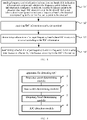
- FIG. 1 is a schematic flowchart of a method for detecting IDC according to an embodiment of the present disclosure.
- the method for detecting IDC shown in this embodiment can be applied to a terminal, which includes but is not limited to an electronic device such as a mobile phone, a tablet computer, and a wearable device
- the terminal can be used as user equipment to communicate with a base station, and the base station may be a LTE base station, and may also be an NR base station.
- the method for detecting IDC may include the following steps.
- step S1 a carrier frequency point to be detected that needs IDC detection is determined according to frequency point indication information sent by the base station.
- step S2 a bandwidth to be detected corresponding to the carrier frequency point to be detected is determined according to bandwidth indication information sent by the base station.
- step S3 a frequency band to be detected is determined according to the carrier frequency point to be detected and the bandwidth to be detected.
- step S4 it is detected whether IDC exists or is to occur in the frequency band to be detected.
- the base station may send the frequency point indication information to the terminal, and the terminal may determine the carrier frequency point to be detected that needs the IDC detection according to the frequency point indication information.
- the frequency point indication information may be the information about the frequency point in the measurement configuration in the related art.
- the frequency point indication information may be the NR candidate service frequency point in the related art.
- the base station can also send the bandwidth indication information to the terminal.
- the terminal can determine the bandwidth to be detected corresponding to the carrier frequency point to be detected, and then can determine the frequency band to be detected according to the carrier frequency point to be detected and the bandwidth to be detected, and then detects whether the IDC exists or is about to occur in the frequency band to be detected.
- the carrier frequency point to be detected may be located at the starting position of the bandwidth to be detected, or at the end position of the bandwidth to be detected, or at the center of the bandwidth to be detected, which specifically, can be pre-agreed between the base station and the terminal.
- the carrier frequency point to be detected is x
- the bandwidth to be detected is A
- the carrier frequency point to be detected is located at the beginning of the bandwidth to be detected, then the frequency band to be detected determined according to the carrier frequency point to be detected and the bandwidth to be detected is x to x+A, thereby detecting whether IDC exists or is about to occur for the frequency band x to x+A.
- the base station in addition to sending the frequency point indication information to the terminal, can also send the bandwidth indication information to the terminal, so that the terminal can determine the carrier frequency point to be detected for IDC detection according to the frequency point indication information, and determine the bandwidth to be detected corresponding to the carrier frequency point to be detected according to the bandwidth indication information, and then determine the frequency band to be detected according to the carrier frequency point to be detected and the bandwidth to be detected, so that the determined frequency band to be detected can be detected to determine whether IDC exists or is about to occur.
- the terminal can be instructed to determine the specific bandwidth to be detected corresponding to the carrier frequency point, so that the terminal can detect the bandwidth to be detected in a targeted manner, without the need for the entire bandwidth of the frequency band where the carrier frequency point is located (for example, the carrier frequency point is a frequency point in the NR frequency band, then the entire bandwidth of the frequency band where the carrier frequency point is located is the bandwidth of the entire NR frequency band).
- the detection can be performed with a smaller granularity, so as to accurately determine which part of the bandwidth corresponding to the carrier frequency point has the IDC, which on one hand, reduces the bandwidth that needs to be detected by the terminal, and on the other hand, makes the IDC information reported by the terminal to the base station is more accurate, which is convenient for the base station to reasonably configure for the terminal according to the IDC information.
- the terminal can use the carrier network, such as 5G NR network, 4G LTE network, etc. to communicate, and can also use the network in other frequency bands, such as Wi-Fi, Bluetooth, GNSS (Global Navigation Satellite System) and other networks for communication.
- Wi-Fi, Bluetooth, GNSS and other networks belong to the ISM (Industrial Scientific Medical) frequency band.
- the frequency band to be detected is mainly the frequency band in the carrier network.
- the IDC can be determined.
- IDC can be predicted. For example, a time period may be preset, called a preset time period, and then it may be predicted whether IDC will occur on the terminal within the preset time period after the current moment. If IDC will occur on the terminal within the preset time period after the current moment, it is determined that IDC will occur.
- the terminal can first determine whether the existing or upcoming IDC can be solved by itself, and in the case that it cannot be solved by itself, the terminal can send information of the IDC to the base station.
- the information of the IDC can indicate to the base station that IDC exists or is about to occur in the frequency band to be detected, so that the base station can configure the terminal.
- the carrier frequency point to be detected may include one frequency point, then the bandwidth to be detected may be one bandwidth, so that one frequency band to be detected can be determined.
- the carrier frequency point to be detected may include multiple frequency points, then the bandwidth to be detected may include multiple bandwidths.
- the base station can also send the correspondence relationship between the carrier frequency points to be detected and the bandwidths to be detected to the terminal. According to the correspondence relationship, the terminal can determine multiple sets of carrier frequency point to be detected and corresponding bandwidth to be detected, and then determine multiple frequency bands to be detected.
- the correspondence relationship is carried in the frequency point indication information or the bandwidth indication information, and may also be carried in other information.
- FIG. 2 is a schematic flowchart of another method for detecting IDC according to an embodiment of the present disclosure.
- the frequency band where IDC exists or is to occur is a target frequency band
- the method further includes: in step S5, sending IDC information of the target frequency band to the base station.
- the terminal determines the frequency band where the IDC exists or will occur as the target frequency band by detecting the frequency point to be detected, and can send the IDC information of the target frequency band to the base station.
- the IDC information may include information about the target frequency band (such as the start and end positions of the target frequency band), so that the base station can determine the frequency band where IDC exists or will occur as the target frequency band, and then configure the terminal to alleviate or eliminate the IDC problem existing in the terminal.
- the target frequency band is a part of the NR frequency band
- the IDC information includes a target carrier frequency point in the target frequency band and a target bandwidth corresponding to the target carrier frequency point.
- the target frequency band where the IDC is determined to exist may be a part of the NR frequency band, then the IDC information reported to the base station may include the target carrier frequency point in the target frequency band and the target bandwidth corresponding to the target carrier frequency point, so that the base station can determine the target frequency band according to the target carrier frequency point and the target bandwidth.
- the target carrier frequency point is located at the starting position of the target bandwidth, then the determined target frequency band is from the target carrier frequency point to the target carrier frequency point plus the target bandwidth.
- the target frequency band is the entire NR frequency band
- the IDC information includes the target carrier frequency point in the target frequency band.
- the terminal may predetermine with the base station, when sending the IDC information to the base station when determining that the target frequency band where the IDC exists corresponds to the entire bandwidth of the frequency band where a certain carrier frequency point is located, the IDC information may only include the carrier frequency point. Then, when the terminal determines that the frequency band where the IDC exists is the entire NR frequency band, the IDC information sent to the base station may only include the target carrier frequency point.
- the base station By analyzing the IDC information, the base station only obtains the target carrier frequency point, but does not obtain the corresponding target bandwidth, and then can determine the frequency band where the target carrier frequency point is located, for example, the frequency band is the NR frequency band, and then can determine that IDC exists in the entire frequency band of the NR frequency band.
- the IDC information is configured to indicate whether the target frequency band is a frequency band causing interference or a frequency band affected by interference.
- the IDC information sent by the terminal to the base station may also indicate the direction of interference, that is, whether the target frequency band is the frequency band that causes interference or the frequency band that is interfered. For example, if the target frequency band causes interference to the ISM frequency band, then the target frequency band is the frequency band causing interference. For example, if the ISM frequency band causes interference to the target frequency band, the target frequency band is the frequency band affected by interference.
- the bandwidth indication information includes a start frequency and an end frequency of the bandwidth to be detected.
- the base station may directly indicate to the terminal the start frequency and end frequency of the bandwidth to be detected through the bandwidth indication information.
- the start frequency and the end frequency may be absolute frequencies, and the terminal can directly determine the frequency band to be detected according to the start frequency and the end frequency (that is, the frequency band from the start frequency to the end frequency is the frequency band to be detected), without considering the carrier frequency point to be detected.
- the bandwidth indication information includes a resource block and a subcarrier spacing.
- the base station may indicate the bandwidth to be detected to the terminal through the bandwidth indication information including the resource block (RBs) and subcarrier spacing (SCS), and the terminal can determine a bandwidth of the resource block (for example, 12 subcarrier spacings) according to the subcarrier spacing, as the bandwidth to be detected.
- the bandwidth indication information including the resource block (RBs) and subcarrier spacing (SCS)
- the terminal can determine a bandwidth of the resource block (for example, 12 subcarrier spacings) according to the subcarrier spacing, as the bandwidth to be detected.
- the bandwidth to be detected is a value of bandwidth, which is A
- the carrier frequency point to be detected x may be located at the starting position of the bandwidth to be detected, then the frequency band to be detected is the frequency band from x to x+A.
- the carrier frequency point to be detected is located at the beginning position of the bandwidth to be detected, or at the end position of the bandwidth to be detected, or at the center of the bandwidth to be detected.
- the carrier frequency point to be detected may be located at the starting position of the bandwidth to be detected, may also be located at the end position of the bandwidth to be detected, or may be located at the center of the bandwidth to be detected, which specifically may be predetermined by the terminal or the base station.
- the carrier frequency point to be detected is x
- the frequency band to be detected is A.
- the frequency band to be detected is the frequency band from x to x+A.
- the frequency band to be detected is the frequency band from x-A to x.
- the frequency band to be detected is from x-A/2 to x+A/2.
- FIG. 3 is a schematic flowchart of yet another method for detecting IDC according to an embodiment of the present disclosure.
- the carrier frequency point to be detected includes an uplink frequency point to be detected and/or a downlink frequency point to be detected, and determining the frequency band to be detected according to the carrier frequency point to be detected and the bandwidth to be detected, and detecting whether IDC exists or is about to occur in the frequency band to be detected includes:
- the operation of the terminal to detect whether IDC exists or is about to occur may be for uplink transmission (for example, whether there is IDC between the frequency band to be detected occupied by uplink transmission and the ISM frequency band), or for downlink transmission (for example, whether there is IDC between the frequency band to be detected occupied by downlink transmission and the ISM frequency band).
- the carrier frequency point to be detected indicated by the base station may include the uplink frequency point to be detected, and may also include the downlink frequency point to be detected.
- the terminal can determine the uplink frequency band to be detected according to the uplink frequency point to be detected and the bandwidth to be detected, and can determine the downlink frequency band to be detected according to the downlink frequency point to be detected and the bandwidth to be detected. Then, when sending information to the base station (that is, during uplink transmission), the terminal can detect whether IDC exists or is about to occur in the uplink frequency band to be detected, or when receiving information sent by the base station (that is, during downlink transmission), the terminal can detect whether IDC exists or is about to occur in the downlink frequency band to be detected.
- the base station indicates the uplink frequency point to be detected to the terminal, so that the terminal determines the uplink frequency band to be detected, and performs detection for the uplink frequency band to be detected, or indicates the downlink frequency point to be detected to the terminal, so that the terminal determines the downlink frequency band to be detected, and performs detection for the downlink frequency band to be detected.
- the uplink frequency point to be detected and the downlink frequency point to be detected may be different, so that the terminal can perform detection on different frequency bands during uplink transmission and downlink transmission.
- the terminal can determine the uplink frequency point to be detected and the downlink frequency point to be detected based on the frequency point.
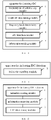
- FIG. 4 is a schematic flowchart of yet another method for detecting IDC according to an embodiment of the present disclosure.
- the carrier frequency points to be detected include an uplink frequency point to be detected and a downlink frequency point to be detected.
- the frequency point indication information includes a first absolute frequency and a first relative frequency
- determining the carrier frequency point to be detected that needs IDC detection according to the frequency point indication information sent by the base station includes: in step S101, determining the uplink frequency point to be detected according to the first absolute frequency, and determining the downlink frequency point to be detected according to the first absolute frequency and the first relative frequency.
- the frequency point indication information includes a second absolute frequency and a second relative frequency
- determining the carrier frequency point to be detected that needs IDC detection according to the frequency point indication information sent by the base station includes: in step S102, determining the downlink frequency point to be detected according to the second absolute frequency, and determining the uplink frequency point to be detected according to the second absolute frequency and the second relative frequency.
- the carrier frequency points to be detected indicated by the base station may include the uplink frequency point to be detected and the downlink frequency point to be detected.
- the frequency point indication information may include the first absolute frequency and the first relative frequency.
- the terminal may determine the uplink frequency point to be detected according to the first absolute frequency, and determine the downlink frequency point to be detected according to the first absolute frequency and the first relative frequency (for example, adding the first relative frequency on the basis of the first absolute frequency).
- the terminal can determine the uplink frequency point to be detected, and by indicating the first absolute frequency and the first relative frequency to the terminal, the terminal can determine the downlink frequency point to be detected.
- the frequency point indication information may also include the second absolute frequency and the second relative frequency.
- the terminal can determine the downlink frequency point to be detected according to the second absolute frequency, and determine the uplink frequency point to be detected according to the second absolute frequency and the second relative frequency (for example, adding the second relative frequency on the basis of the second absolute frequency).
- the terminal can determine the downlink frequency point to be detected, and by indicating the second absolute frequency and the second relative frequency to the terminal, the terminal can determine the uplink frequency point to be detected.
- FIG. 5 is a schematic flowchart of yet another method for detecting IDC according to an embodiment of the present disclosure.
- the bandwidth to be detected includes an uplink bandwidth to be detected and/or a downlink bandwidth to be detected, and determining the frequency band to be detected according to the carrier frequency point to be detected and the bandwidth to be detected, and detecting whether IDC exists or is to occur in the frequency band to be detected includes:
- the operation of the terminal to detect whether IDC exists or is about to occur may be for uplink transmission (for example, whether there is IDC between the frequency band to be detected occupied by uplink transmission and the ISM frequency band), or for downlink transmission (for example, whether there is IDC between the frequency band to be detected occupied by downlink transmission and the ISM frequency band), and the bandwidth to be detected indicated by the base station may include the uplink bandwidth to be detected, and may also include the downlink bandwidth to be detected.
- the terminal can determine the uplink frequency band to be detected according to the frequency point to be detected and the uplink bandwidth to be detected, and can determine the downlink frequency band to be detected according to the frequency point to be detected and the downlink bandwidth to be detected. Then, when sending information to the base station (that is, during uplink transmission), the terminal can detect whether IDC exists or is about to occur in the uplink frequency band to be detected, or when receiving information sent from the base station (that is, during downlink transmission), the terminal can detect whether IDC exists or is to occur in the downlink frequency band to be detected.
- the base station indicates the uplink bandwidth to be detected to the terminal, so that the terminal determines the uplink frequency band to be detected, and performs detection for the uplink frequency band to be detected, or indicates the downlink bandwidth to be detected to the terminal, so that the terminal determines the downlink frequency band to be detected, and performs detection for the downlink frequency band to be detected.
- the uplink bandwidth to be detected and the downlink bandwidth to be detected may be different, so that the terminal can perform detection on different frequency bands during uplink transmission and downlink transmission.
- the terminal may determine the uplink bandwidth to be detected and the downlink bandwidth to be detected based on the bandwidth.
- the bandwidth indication information includes configuration information of bandwidth parts of the frequency band corresponding to the serving cell.
- the NR frequency band can be divided into multiple bandwidth parts (BWP for short), and for the terminal, the base station can inform the terminal of the specific configuration of the bandwidth parts of the frequency band corresponding to the serving cell through the configuration information (for example, how many bandwidth parts the corresponding frequency of the serving cell contains, the center frequency point of each bandwidth part, the bandwidth size of each bandwidth part, etc.).
- the bandwidth indication information sent by the base station to the terminal may be included in the configuration information of the bandwidth parts of the frequency band corresponding to the serving cell, and the terminal can determine the bandwidth to be detected according to the configuration information, for example, the bandwidth of the bandwidth part corresponding to the serving cell can be used as the bandwidth to be detected.
- the frequency point indication information may also be included in the configuration information, that is, the base station does not need to send the frequency point indication information and bandwidth indication information, but can indicate the carrier frequency point to be detected (for example, the terminal can use the center frequency point of the corresponding bandwidth part of the current serving cell or all serving cells as the carrier frequency point to be detected) and the bandwidth to be detected to the terminal through the configuration information.
- the base station can send the frequency point indication information and the bandwidth indication information to the terminal through separate information.
- the serving cell corresponds to multiple bandwidth parts
- the bandwidth to be detected is the sum of the bandwidths of the multiple bandwidth parts, or the sum of the bandwidths of some of the multiple bandwidth parts.
- the base station can carry the bandwidth indication information in the configuration information to send the configuration information to the terminal, and the terminal can determine the bandwidth to be detected according to the configuration information. Specifically, the terminal can determine the bandwidths of multiple bandwidth parts corresponding to the serving cell according to the configuration information, and then add the bandwidths of the multiple bandwidth parts as the bandwidth to be detected, or add the bandwidths of some of the bandwidth parts (specifically, which bandwidth parts among the multiple bandwidth parts may be pre-agreed by the terminal and the base station) as the bandwidth to be detected.
- the terminal is in an idle state or an inactive state
- the carrier frequency point to be detected is the frequency point at which the base station instructs the terminal to perform carrier measurement in the idle state or the inactive state.
- the base station may instruct the terminal to perform carrier measurement (for example, to measure the carrier for the purpose of minimizing drive test, etc.), and the carrier indication information may be included in the instruction for instructing the terminal to perform carrier measurement. Accordingly, the terminal can determine the frequency band to be detected according to the frequency point to be detected for the carrier measurement.
- FIG. 6 is a schematic flowchart of a method for indicating IDC detection according to an embodiment of the present disclosure.
- the method for indicating IDC detection shown in this embodiment can be applied to a base station, and the base station can communicate with the terminal in the method for detecting IDC described in any of the above embodiments, and the terminal can communicate with the base station as a user equipment.
- the base station may be an LTE base station or an NR base station.
- the method for indicating IDC detection may include the following steps.
- step S1' frequency point indication information and bandwidth indication information is sent to the terminal.
- the frequency point indication information is configured to indicate the carrier frequency point to be detected that needs IDC detection
- the bandwidth indication information is configured to indicate the bandwidth to be detected corresponding to the carrier frequency point to be detected.
- the base station can not only send the frequency point indication information to the terminal, but also can send the bandwidth indication information to the terminal, so that the terminal can determine the carrier frequency point to be detected for IDC detection according to the frequency point indication information, and determine the bandwidth to be detected corresponding to the carrier frequency point to be detected according to the bandwidth indication information, and further determines the frequency band to be detected according to the carrier frequency point to be detected and the bandwidth to be detected, so that the determined frequency band to be detected can be detected to determine whether IDC exists or is about to occur.
- the terminal can be instructed to determine the specific bandwidth to be detected corresponding to the carrier frequency point, and then the terminal can detect the bandwidth to be detected in a targeted manner, without the need for the entire bandwidth of the frequency band where the carrier frequency point is located (for example, the carrier frequency point is a frequency point in the NR frequency band, then the entire bandwidth of the frequency band where the carrier frequency point is located is the bandwidth of the entire NR frequency band).
- the detection can be performed with a smaller granularity, so as to accurately determine which part of the bandwidth corresponding to the carrier frequency point has the IDC, which on one hand, reduces the bandwidth that needs to be detected by the terminal, and on the other hand, makes the IDC information reported by the terminal to the base station is more accurate, which is convenient for the base station to reasonably configure for the terminal according to the IDC information.
- FIG. 7 is a schematic flowchart of another method for indicating IDC detection according to an embodiment of the present disclosure. As shown in FIG. 7 , the method further includes:
- the terminal determines the frequency point where the IDC exists or is about to occur as the target frequency band, and can send the IDC information that the IDC exists in the target frequency band to the base station.
- the IDC information may include information related to the target frequency band (such as the start position and end position of the target frequency band).
- the base station can determine that the IDC exists in the target frequency band according to the information of the target frequency band, and further can configure the terminal to alleviate or eliminate the IDC problem existing in the terminal.
- the target frequency band is a part of the NR frequency band
- the information of the target frequency band includes a target carrier frequency point of the target frequency band and a target bandwidth corresponding to the target carrier frequency point.
- the target frequency band determined to have IDC may be a part of the NR frequency band, then the IDC information received by the base station may include the target carrier frequency point of the target frequency band and the target bandwidth corresponding to the target carrier frequency point, and the base station can determine the target frequency band according to the target carrier frequency point and the target bandwidth. For example, the target carrier frequency point is located at the starting position of the target bandwidth, then the determined target frequency band is from the target carrier frequency point to the target carrier frequency point plus the target bandwidth.
- the target frequency band is the entire NR frequency band
- the IDC information includes the target carrier frequency point of the target frequency band.
- the terminal can pre-determine with the base station, when sending the IDC information to the base station in response to determining that the target frequency band where the IDC exists corresponds to the entire bandwidth of the frequency band where a certain carrier frequency point is located, the IDC information can only include the carrier frequency band. Then, when the terminal determines that the frequency band where the IDC exists is the entire NR frequency band, the IDC information sent to the base station may only include the target carrier frequency point.
- the base station By analyzing the IDC information, the base station only obtains the target carrier frequency point, but does not obtain the corresponding target bandwidth, and can determine the frequency band where the target carrier frequency point is located.
- the frequency band where the target carrier frequency point is located is the NR frequency band, and it can be determined that the IDC exists in the entire NR frequency band.
- FIG. 8 is a schematic flowchart of yet another method for indicating IDC detection according to an embodiment of the present disclosure. As shown in FIG. 8 , the method further includes: in step S4', determining whether the target frequency band is a frequency band causing interference or affected by interference according to the IDC information.
- the base station can also determine the interference direction according to the received IDC information, that is, whether the target frequency band is the frequency band causing interference or affected by interference. For example, if the target frequency band causes interference to the ISM frequency band, then the target frequency band is the frequency band causing interference. For example, if the ISM frequency band causes interference to the target frequency band, the target frequency band is the interference-affected frequency band.
- the bandwidth indication information includes a start frequency and an end frequency of the bandwidth to be detected.
- the base station may directly indicate to the terminal the start frequency and end frequency of the bandwidth to be detected through the bandwidth indication information.
- the start frequency and the end frequency may be absolute frequencies, and the terminal can directly determine the frequency band to be detected according to the start frequency and the end frequency (that is, the frequency band from the start frequency to the end frequency is the frequency band to be detected), without considering the carrier frequency point to be detected.
- the bandwidth indication information includes a resource block and a subcarrier spacing.
- the base station may indicate the bandwidth to be detected to the terminal through the bandwidth indication information including the resource block and the subcarrier spacing, and the terminal may determine the bandwidth of the resource block (for example, 12 subcarrier spacings) as the bandwidth to be detected according to the subcarrier spacing.
- the base station may indicate the bandwidth to be detected to the terminal, which is not limited to the content described in the above-mentioned embodiments.
- the bandwidth to be detected is a value of a bandwidth, and the value is A.
- the carrier frequency point to be detected x may be located at the starting position of the bandwidth to be detected, then the frequency band to be detected is the frequency band from x to x+A.
- the carrier frequency point to be detected is located at the starting position of the bandwidth to be detected, or at the end position of the bandwidth to be detected, or at the center of the bandwidth to be detected.
- the carrier frequency point to be detected may be located at the starting position of the bandwidth to be detected, also may be located at the end position of the bandwidth to be detected, and may also be located at the center of the bandwidth to be detected, which may be specifically predetermined by the terminal and the base station.
- the carrier frequency point to be detected is x
- the frequency band to be detected is A.
- the frequency band to be detected is the frequency band from x to x+A.
- the frequency band to be detected is the frequency band from x-A to x.
- the frequency band to be detected is the frequency band from x-A/2 to x+A/2.
- the carrier frequency point to be detected includes an uplink frequency point to be detected and/or a downlink frequency point to be detected.
- the base station indicates the uplink frequency point to be detected to the terminal, so that the terminal determines the uplink frequency band to be detected, and detects the uplink frequency band to be detected, or indicates the downlink frequency point to be detected to the terminal, so that The terminal determines the downlink frequency band to be detected, and detects the downlink frequency band to be detected.
- the uplink frequency point to be detected and the downlink frequency point to be detected may be different, so that the terminal can perform detection on different frequency bands during uplink transmission and downlink transmission.
- the carrier frequency point to be detected includes the uplink frequency point to be detected and the downlink frequency point to be detected.
- the frequency point indication information includes a first absolute frequency and a first relative frequency, or the frequency point indication information includes a second absolute frequency and a second relative frequency.
- the terminal by indicating the first absolute frequency to the terminal, the terminal can determine the uplink frequency point to be detected, and by indicating the first absolute frequency and the first relative frequency to the terminal, the terminal can determine the downlink frequency point to be detected.
- the terminal by indicating the second absolute frequency to the terminal, the terminal can determine the downlink frequency point to be detected, and by indicating the second absolute frequency and the second relative frequency to the terminal, the terminal can determine the uplink frequency point to be detected.
- the bandwidth to be detected includes an uplink bandwidth to be detected and/or a downlink bandwidth to be detected.
- the base station indicates the uplink bandwidth to be detected to the terminal, so that the terminal determines the uplink frequency band to be detected, and performs detection for the uplink frequency band to be detected, or indicates the downlink bandwidth to be detected to the terminal, so that the terminal determines the downlink frequency band to be detected, and performs detection for the downlink frequency band to be detected.
- the uplink bandwidth to be detected and the downlink bandwidth to be detected may be different, so that the terminal can perform detection on different frequency bands during uplink transmission and downlink transmission.
- the bandwidth indication information includes configuration information of the bandwidth parts of the frequency band corresponding to the serving cell.
- the bandwidth indication information sent by the base station to the terminal may be included in the configuration information of the bandwidth parts of the frequency band corresponding to the serving cell, and the terminal can determine the bandwidth to be detected according to the configuration information, for example, the bandwidth of the bandwidth part corresponding to the serving cell can be used as the bandwidth to be detected.
- the serving cell corresponds to multiple bandwidth parts
- the bandwidth to be detected is the sum of the bandwidths of the multiple bandwidth parts, or the sum of the bandwidths of some of the multiple bandwidth parts.
- the base station can carry the bandwidth indication information in the configuration information to send the configuration information to the terminal, and the terminal can determine the bandwidth to be detected according to the configuration information. Specifically, the terminal can determine the bandwidths of multiple bandwidth parts corresponding to the serving cell according to the configuration information, and then add the bandwidths of the multiple bandwidth parts as the bandwidth to be detected, or add the bandwidths of some of the bandwidth parts (specifically, which bandwidth parts among the multiple bandwidth parts may be pre-agreed by the terminal and the base station) as the bandwidth to be detected.
- the carrier frequency point to be detected is the frequency point at which the base station instructs the terminal to perform carrier measurement in an idle state or an inactive state.
- the base station may instruct the terminal to perform carrier measurement (for example, to measure the carrier for the purpose of minimizing drive test, etc.), and the carrier indication information may be included in the instruction for instructing the terminal to perform carrier measurement. Accordingly, the terminal can determine the frequency band to be detected according to the frequency point to be detected for the carrier measurement.
- the present disclosure also provides embodiments of an apparatus for detecting IDC and an apparatus for indicating IDC detection.
- FIG. 9 is a schematic block diagram of an apparatus for detecting IDC according to an embodiment of the present disclosure.
- the apparatus for detecting IDC shown in this embodiment can be applied to a terminal, which includes but is not limited to an electronic device such as a mobile phone, a tablet computer, and a wearable device.
- the terminal can be used as user equipment to communicate with a base station, and the base station may be an LTE base station, and may also be an NR base station.
- the apparatus for detecting IDC may include a frequency point determining module 1, a bandwidth determining module 2, a frequency band determining module 3 and an IDC detection module 4.
- the frequency point determining module 1 is configured to determine a carrier frequency point to be detected that needs IDC detection according to frequency point indication information sent by the base station.
- the bandwidth determining module 2 is configured to determine a bandwidth to be detected corresponding to the carrier frequency point to be detected according to bandwidth indication information sent by the base station.
- the frequency band determining module 3 is configured to determine a frequency band to be detected according to the carrier frequency point to be detected and the bandwidth to be detected.
- the IDC detection module 4 is configured to detect whether IDC exists or is to occur in the frequency band to be detected.
- FIG. 10 is a schematic block diagram of another apparatus for detecting IDC according to an embodiment of the present disclosure.
- the target frequency band where IDC exists or is to occur is the target frequency band, and the apparatus further includes an information sending module 5.
- the information sending module 5 is configured to send IDC information of the target frequency band to the base station.
- the target frequency band is a part of the NR frequency band
- the IDC information includes a target carrier frequency point of the target frequency band and a target bandwidth corresponding to the target carrier frequency point.
- the target frequency band is the entire NR frequency band
- the IDC information includes the target carrier frequency point of the target frequency band.
- the IDC information is configured to indicate whether the target frequency band is a frequency band causing interference or affected by interference.
- the bandwidth indication information includes a start frequency and an end frequency of the bandwidth to be detected.
- the bandwidth indication information includes a resource block and a subcarrier spacing.
- the carrier frequency point to be detected is located at the starting position of the bandwidth to be detected, or at the end position of the bandwidth to be detected, or at the center of the bandwidth to be detected.
- the carrier frequency point to be detected includes an uplink frequency point to be detected and/or a downlink frequency point to be detected.
- the frequency point determining module is configured to determine an uplink frequency band to be detected according to the uplink frequency point to be detected and the bandwidth to be detected, and/or determine the downlink frequency band to be detected according to the downlink frequency point to be detected and the bandwidth to be detected.
- the bandwidth determining module is configured to, when the terminal sends information to the base station, detect whether IDC exists or is to occur in the uplink frequency band to be detected, and/or when the terminal receives information sent by the base station, detect whether IDC exists or is to occur in the downlink frequency band to be detected.
- the carrier frequency point to be detected includes an uplink frequency point to be detected and a downlink frequency point to be detected.
- the frequency point indication information includes a first absolute frequency and a first relative frequency
- the frequency point determining module is configured to determine the uplink frequency point to be detected according to the first absolute frequency, and determine the downlink frequency point to be detected according to the first absolute frequency and the first relative frequency.
- the frequency point indication information includes a second absolute frequency and a second relative frequency
- the frequency point determining module is configured to determine the downlink frequency point to be detected according to the second absolute frequency, determine the uplink frequency point to be detected according to the second absolute frequency and the second relative frequency.
- the bandwidth to be detected includes an uplink bandwidth to be detected and/or a downlink bandwidth to be detected.
- the frequency point determining module is configured to determine the uplink frequency band to be detected according to the frequency point to be detected and the uplink bandwidth to be detected, and/or determine the downlink frequency band to be detected according to the frequency point to be detected and the downlink bandwidth to be detected.
- the bandwidth determining module is configured to, when the terminal sends information to the base station, detect whether IDC exists or is to occur in the uplink frequency band to be detected, and/or when the terminal receives information sent by the base station, detect whether IDC exists or is to occur in the downlink frequency band to be detected.
- the bandwidth indication information includes configuration information of bandwidth part of the frequency band corresponding to the serving cell.
- the serving cell corresponds to multiple bandwidth parts
- the bandwidth to be detected is the sum of bandwidths of the multiple bandwidth parts, or the sum of the bandwidths of some of the multiple bandwidth parts.
- the terminal is in an idle state or an inactive state
- the carrier frequency point to be detected is a frequency point at which the base station instructs the terminal to perform carrier measurement in the idle state or the inactive state.
- FIG. 11 is a schematic block diagram of an apparatus for indicating IDC detection according to an embodiment of the present disclosure.
- the apparatus for indicating IDC detection shown in this embodiment can be applied to a base station, and the base station can communicate with the terminal in the method for detecting IDC described in any of the above embodiments.
- the terminal can communicate with the base station as a user equipment.
- the base station may be an LTE base station or an NR base station.
- the apparatus for indicating IDC detection may include an indication sending module 1'.
- the indication sending module 1' is configured to send frequency point indication information and bandwidth indication information to terminal.
- the frequency point indication information is configured to indicate a carrier frequency point to be detected that needs IDC detection
- the bandwidth indication information is configured to indicate a bandwidth to be detected corresponding to the carrier frequency point to be detected.
- FIG. 12 is a schematic block diagram of another apparatus for indicating IDC detection according to an embodiment of the present disclosure. As shown in FIG. 12 , the apparatus further includes an information receiving module 2' and an IDC determining module 3'.
- the information receiving module 2' is configured to receive IDC information sent by the terminal.
- the IDC determining module 3' is configured to determine, according to the IDC information, information of a target frequency band where IDC exists or is about to occur.
- the target frequency band is a part of the NR frequency band
- the information of the target frequency band includes a target carrier frequency point of the target frequency band and a target bandwidth corresponding to the target carrier frequency point.
- the target frequency band is the entire NR frequency band
- the information of the IDC includes the target carrier frequency point of the target frequency band.
- FIG. 13 is a schematic block diagram of yet another apparatus for indicating IDC detection according to an embodiment of the present disclosure. As shown in FIG. 13 , the apparatus further includes a direction determining module 4'.
- the direction determining module 4' is configured to determine, according to the IDC information, whether the target frequency band is a frequency band causing interference or affected by interference.
- the bandwidth indication information includes a start frequency and an end frequency of the bandwidth to be measured.
- the bandwidth indication information includes a resource block and a subcarrier spacing.
- the carrier frequency point to be detected is located at the starting position of the bandwidth to be detected, or at the end position of the bandwidth to be detected, or at the center of the bandwidth to be detected.
- the carrier frequency point to be detected includes an uplink frequency point to be detected and/or a downlink frequency point to be detected.
- the carrier frequency point to be detected includes an uplink frequency point to be detected and a downlink frequency point to be detected.
- the frequency point indication information includes a first absolute frequency and a first relative frequency, or the frequency point indication information includes a second absolute frequency and a second relative frequency.
- the bandwidth to be measured includes an uplink bandwidth to be detected and/or a downlink bandwidth to be detected.
- the bandwidth indication information includes the configuration information of the bandwidth part of the frequency band corresponding to the serving cell.
- the serving cell corresponds to multiple bandwidth parts
- the bandwidth to be detected is the sum of the bandwidths of the multiple bandwidth parts, or the sum of the bandwidths of some of the multiple bandwidth parts.
- the carrier frequency point to be detected is the frequency point at which the base station instructs the terminal to perform carrier measurement in an idle state or an inactive state.
- An embodiment of the present disclosure also proposes an electronic device, including:
- the processor is configured to implement the method for detecting IDC described in any of the above embodiments.
- An embodiment of the present disclosure also proposes an electronic device, including:
- the processor is configured to implement the method for indicating IDC detection described in any of the above embodiments.
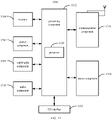
- FIG. 14 is a schematic block diagram of an apparatus 1400 for indicating IDC detection according to an embodiment of the present disclosure.
- the apparatus 1400 may be provided as a base station. 14.
- the apparatus 1400 includes a processing component 1422, a wireless transmitting/receiving component 1424, an antenna component 1426, and a signal processing part specific to a wireless interface, and the processing component 1422 may further include one or more processors.
- One of the processors in the processing component 1422 may be configured to implement the method for indicating IDC detection described in any of the foregoing embodiments.
- FIG. 15 is a schematic block diagram of an apparatus 1500 for detecting IDC acco rding to an embodiment of the disclosure.
- the apparatus 1500 may be a mobile phone, a computer, a digital broadcasting terminal, a message transceiver device, a game console, a tablet device, a medical device, a fitness device and a personal digit al assistant.
- the apparatus 1500 may include one or more of the following components: a processing component 1502, a memory 1504, a power component 1506, a multimedia component 1508, an audio component 1510, an input/output (I/O) interface 1512, a sensor component 1514, and a communication component 1516.
- the processing component 1502 generally controls overall operation of the apparatus 1500, such as the operations associated with display, telephone calls, data communications, camera operations, and recording operations.
- the processing component 1502 may include one or more processors 1520 to execute instructions to perform all or part of the steps in the above described method.
- the processing component 1502 may include one or more modules which facilitate the interaction between the processing component 1502 and other components.
- the processing component 1502 may include a multimedia module to facilitate the interaction between the multimedia component 1508 and the processing component 1502.
- the memory 1504 is configured to store various types of data to support the operation of the apparatus 1500. Examples of such data include instructions for any applications or methods operated on the apparatus 1500, contact data, phonebook data, messages, pictures, video, etc.
- the memory 1504 may be implemented using any type of volatile or non-volatile memory devices, or a combination thereof, such as a static random access memory (SRAM), an electrically erasable programmable read-only memory (EEPROM), an erasable programmable read-only memory (EPROM), a programmable read-only memory (PROM), a read-only memory (ROM), a magnetic memory, a flash memory, a magnetic or optical disk.
- SRAM static random access memory
- EEPROM electrically erasable programmable read-only memory
- EPROM erasable programmable read-only memory
- PROM programmable read-only memory
- ROM read-only memory
- magnetic memory a magnetic memory
- flash memory a flash memory
- magnetic or optical disk a magnetic or optical
- the power component 1506 provides power to various components of the apparatus 1500.
- the power component 1506 may include a power management system, one or more power sources, and any other components associated with the generation, management, and distribution of power in the apparatus 1500.
- the multimedia component 1508 includes a screen providing an output interface between the apparatus 1500 and the user.
- the screen may include a liquid crystal display (LCD) and a touch panel (TP). If the screen includes the touch panel, the screen may be implemented as a touch screen to receive input signals from the user.
- the touch panel includes one or more touch sensors to sense touches, swipes, and gestures on the touch panel. The touch sensors may not only sense a boundary of a touch or swipe action, but also sense a period of time and a pressure associated with the touch or swipe action.
- the multimedia component 1508 includes a front-facing camera and/or a rear-facing camera.
- the front-facing camera and/or the rear-facing camera can receive external multimedia data.
- Each front-facing camera and rear-facing camera may be a fixed optical lens system or has focal length and optical zoom capability.
- the audio component 1510 is configured to output and/or input audio signals.
- the audio component 1510 includes a microphone (MIC) configured to receive an external audio signal when the apparatus 1500 is in an operation mode, such as a call mode, a recording mode, and a voice recognition mode.
- the received audio signal may be further stored in the memory 1504 or transmitted via the communication component 1516.
- the audio component 1510 further includes a speaker to output audio signals.
- the I/O interface 1512 provides an interface between the processing component 1502 and peripheral interface modules, such as a keyboard, a click wheel, buttons, and the like.
- the buttons may include, but are not limited to, a home button, a volume button, a starting button, and a locking button.
- the sensor component 1514 includes one or more sensors to provide status assessments of various aspects of the apparatus 1500. For instance, the sensor component 1514 may detect an open/closed status of the apparatus 1500, relative positioning of components, e.g., the display and the keypad, of the apparatus 1500, a change in position of the apparatus 1500 or a component of the apparatus 1500, a presence or absence of user contact with the apparatus 1500, an orientation or an acceleration/deceleration of the apparatus 1500, and a change in temperature of the apparatus 1500.
- the sensor component 1514 may include a proximity sensor configured to detect the presence of nearby objects without any physical contact.
- the sensor component 1514 may also include a light sensor, such as a CMOS or CCD image sensor, for use in imaging applications.
- the sensor component 1514 may also include an accelerometer sensor, a gyroscope sensor, a magnetic sensor, a pressure sensor, or a temperature sensor.
- the communication component 1516 is configured to facilitate communication, wired or wirelessly, between the apparatus 1500 and other devices.
- the apparatus 1500 can access a wireless network based on a communication standard, such as WiFi, 2G, or 3G, or a combination thereof.
- the communication component 1516 receives a broadcast signal or broadcast associated information from an external broadcast management system via a broadcast channel.
- the communication component 1516 further includes a near field communication (NFC) module to facilitate short-range communications.
- the NFC module may be implemented based on a radio frequency identity (RFID) technology, an infrared data association (IrDA) technology, an ultra-wideband (UWB) technology, a Bluetooth (BT) technology, and other technologies.
- RFID radio frequency identity
- IrDA infrared data association
- UWB ultra-wideband
- BT Bluetooth
- the apparatus 1500 may be implemented with one or more application specific integrated circuits (ASICs), digital signal processors (DSPs), digital signal processing devices (DSPDs), programmable logic devices (PLDs), field programmable gate arrays (FPGAs), controllers, micro-controllers, microprocessors, or other electronic components, for performing the above described method.
- ASICs application specific integrated circuits
- DSPs digital signal processors
- DSPDs digital signal processing devices
- PLDs programmable logic devices
- FPGAs field programmable gate arrays
- controllers micro-controllers, microprocessors, or other electronic components, for performing the above described method.
- non-transitory computer readable storage medium including instructions, such as included in the memory 1504, executable by the processor 1520 in the apparatus 1500, for performing the above method.
- the non-transitory computer-readable storage medium may be a ROM, a RAM, a CD-ROM, a magnetic tape, a floppy disc, an optical data storage device, and the like.
Landscapes
- Engineering & Computer Science (AREA)
- Computer Networks & Wireless Communication (AREA)
- Signal Processing (AREA)
- Mobile Radio Communication Systems (AREA)
Applications Claiming Priority (1)
| Application Number | Priority Date | Filing Date | Title |
|---|---|---|---|
| PCT/CN2019/104243 WO2021042272A1 (zh) | 2019-09-03 | 2019-09-03 | Idc检测方法和装置、idc检测指示方法和装置 |
Publications (3)
| Publication Number | Publication Date |
|---|---|
| EP4027682A1 true EP4027682A1 (de) | 2022-07-13 |
| EP4027682A4 EP4027682A4 (de) | 2023-06-14 |
| EP4027682B1 EP4027682B1 (de) | 2026-04-15 |
Family
ID=69274571
Family Applications (1)
| Application Number | Title | Priority Date | Filing Date |
|---|---|---|---|
| EP19944517.2A Active EP4027682B1 (de) | 2019-09-03 | 2019-09-03 | Idc-detektionsverfahren und -vorrichtung und idc-detektionsanzeigeverfahren und -vorrichtung |
Country Status (4)
| Country | Link |
|---|---|
| US (1) | US12549974B2 (de) |
| EP (1) | EP4027682B1 (de) |
| CN (1) | CN110741669B (de) |
| WO (1) | WO2021042272A1 (de) |
Families Citing this family (4)
| Publication number | Priority date | Publication date | Assignee | Title |
|---|---|---|---|---|
| GB2593959A (en) * | 2019-12-12 | 2021-10-13 | Samsung Electronics Co Ltd | Improvements in and relating to telecommunications systems |
| US12470965B2 (en) * | 2020-06-19 | 2025-11-11 | Beijing Xiaomi Mobile Software Co., Ltd. | Method for processing overheat of the UE communication device, and storage medium |
| CN119908098A (zh) * | 2022-11-03 | 2025-04-29 | Oppo广东移动通信有限公司 | 无线通信的方法、终端设备和网络设备 |
| CN119922590B (zh) * | 2023-10-31 | 2025-12-19 | 中国移动通信有限公司研究院 | 测试方法、装置、测试设备及存储介质 |
Family Cites Families (23)
| Publication number | Priority date | Publication date | Assignee | Title |
|---|---|---|---|---|
| CN102378299B (zh) * | 2010-08-10 | 2015-03-11 | 电信科学技术研究院 | 避免设备内共存干扰的测量上报方法及设备 |
| US9769833B2 (en) * | 2010-10-29 | 2017-09-19 | Samsung Electronics Co., Ltd. | Method and apparatus for handling in-device co-existence interference in a user equipment |
| US8638746B2 (en) * | 2010-11-04 | 2014-01-28 | Ntt Docomo, Inc. | Method and apparatus for the joint design and operation of scheduling and transmission for downlink multi-user MIMO with reciprocity-based training |
| KR101871014B1 (ko) * | 2011-01-07 | 2018-06-25 | 삼성전자주식회사 | Ism에 사용될 수 있는 주파수 정보를 기지국에 전달하는 방법 및 장치 |
| CN102595465B (zh) * | 2011-01-10 | 2018-07-17 | 中兴通讯股份有限公司 | 一种实现干扰信息上报的方法、系统及ue |
| CN102740348B (zh) * | 2011-04-02 | 2017-07-11 | 中兴通讯股份有限公司 | 一种测量处理方法及系统 |
| US8934846B2 (en) * | 2011-04-27 | 2015-01-13 | Lg Electronics Inc. | Method and wireless apparatus for performing a minimization drive test |
| WO2013085256A1 (en) * | 2011-12-05 | 2013-06-13 | Samsung Electronics Co., Ltd. | Method and system for handling in-device co-existence interference in user equipment |
| CN103220048B (zh) * | 2012-01-20 | 2018-04-27 | 中兴通讯股份有限公司 | 一种进行测量处理的方法及装置 |
| KR20130087309A (ko) * | 2012-01-27 | 2013-08-06 | 주식회사 팬택 | 무선통신 시스템에서 기기 내 공존 간섭을 제어하는 장치 및 방법 |
| WO2013115514A1 (ko) * | 2012-02-01 | 2013-08-08 | 엘지전자 주식회사 | 무선 통신 시스템에서 채널 측정 정보를 전송하는 방법 및 이를 위한 장치 |
| CN103249076A (zh) * | 2012-02-06 | 2013-08-14 | 中兴通讯股份有限公司 | 参考信号测量方法及装置 |
| WO2014094238A1 (zh) * | 2012-12-18 | 2014-06-26 | 华为技术有限公司 | 设备内多无线技术共存idc干扰处理方法及设备 |
| US9602266B2 (en) * | 2013-11-04 | 2017-03-21 | Marvell World Trade Ltd. | Method and apparatus for scheduling use of radio resources in a wireless network |
| US9985756B2 (en) * | 2014-01-29 | 2018-05-29 | Samsung Electronics Co., Ltd. | Multicarrier-based data transmission method and apparatus in mobile communication system |
| MX375806B (es) * | 2015-08-14 | 2025-03-07 | Ericsson Telefon Ab L M | Señalización de problemas de idc. |
| WO2017052343A1 (en) * | 2015-09-25 | 2017-03-30 | Samsung Electronics Co., Ltd. | Terminal and communication method of the same |
| CN108934041B (zh) * | 2017-05-27 | 2021-02-12 | 维沃移动通信有限公司 | 一种测量事件处理方法、相关设备和系统 |
| CN109803282B (zh) * | 2017-11-16 | 2021-05-14 | 维沃移动通信有限公司 | 测量信号的方法和设备 |
| EP3500038B1 (de) * | 2017-12-13 | 2019-10-23 | ASUSTek Computer Inc. | Verfahren und vorrichtung zum handhaben eines bwp-inaktivitäts-timers während des wahlfreien zugriffsverfahrens in einem drahtloskommunikationssystem |
| CN110831174B (zh) * | 2018-08-09 | 2024-11-12 | 中兴通讯股份有限公司 | 信息传输方法及装置 |
| CN111526586B (zh) * | 2019-02-01 | 2024-04-12 | 华为技术有限公司 | 一种通信的方法和装置 |
| WO2021026857A1 (en) * | 2019-08-15 | 2021-02-18 | Qualcomm Incorporated | New radio in-device coexistence in wideband system |
-
2019
- 2019-09-03 EP EP19944517.2A patent/EP4027682B1/de active Active
- 2019-09-03 CN CN201980001884.3A patent/CN110741669B/zh active Active
- 2019-09-03 US US17/639,867 patent/US12549974B2/en active Active
- 2019-09-03 WO PCT/CN2019/104243 patent/WO2021042272A1/zh not_active Ceased
Also Published As
| Publication number | Publication date |
|---|---|
| EP4027682A4 (de) | 2023-06-14 |
| US20220338037A1 (en) | 2022-10-20 |
| US12549974B2 (en) | 2026-02-10 |
| WO2021042272A1 (zh) | 2021-03-11 |
| EP4027682B1 (de) | 2026-04-15 |
| CN110741669A (zh) | 2020-01-31 |
| CN110741669B (zh) | 2024-02-09 |
Similar Documents
| Publication | Publication Date | Title |
|---|---|---|
| US12127240B2 (en) | Methods and apparatuses for triggering bandwidth part handover, and methods and apparatuses for information configuration | |
| US11956809B2 (en) | Resource determining methods and apparatuses | |
| EP4057671A1 (de) | Verfahren und vorrichtung zur ressourcenzuteilung einer strahlausfallserkennung und speichermedium | |
| US12432764B2 (en) | Method for in-device coexistence interference indication and method and apparatus for in-device coexistence interference receiving | |
| EP3836602A1 (de) | Verfahren und vorrichtung zur messung von zellen sowie vorrichtung und speichermedium | |
| US12549974B2 (en) | Method and apparatus for detecting IDC, and method and apparatus for indicating IDC detection | |
| EP4167659A1 (de) | Drahtloskommunikationsverfahren und -vorrichtung, endgerät und speichermedium | |
| CN110574410B (zh) | 设备内共存干扰指示方法、接收方法和装置 | |
| US11076311B2 (en) | Methods and devices for measuring cell signal quality | |
| EP3771232B1 (de) | Informationsmeldungs- und konfigurationsverfahren und vorrichtung, benutzergerät und basisstation | |
| EP3739952A1 (de) | Verfahren und vorrichtung zur anzeige des zelltyps | |
| US12587294B2 (en) | Modulation and coding scheme (MCS) configuration method and apparatus, and communication device | |
| CN115152287B (zh) | 一种参数配置方法、参数配置装置及存储介质 | |
| EP4564956A1 (de) | Verfahren und vorrichtung zur uplink-übertragungsumschaltung sowie verfahren und vorrichtung zur anzeige einer uplink-übertragungsumschaltung | |
| US20240195522A1 (en) | Method for sending downlink information, method for receiving downlink information, and device | |
| US20240340874A1 (en) | Method and apparatus for frequency band indication, and method and apparatus for frequency band determination | |
| CN110603847B (zh) | 小区重选方法和装置、电子设备以及计算机可读存储介质 | |
| US20240064708A1 (en) | Resource configuration method and apparatus, and resource determination method and apparatus | |
| EP4668938A1 (de) | Informationsübertragungsverfahren und -vorrichtung, kommunikationsvorrichtung und speichermedium | |
| CN109451821B (zh) | 数据分流指示方法及装置、数据分流方法及装置和接入点 | |
| EP4564957A1 (de) | Verfahren und vorrichtung zur bestimmung der anzahl von uplink-übertragungsverbindungen, kommunikationsvorrichtung und speichermedium | |
| JP7794998B2 (ja) | 干渉情報報告方法、周波数範囲決定方法及び装置 | |
| EP3751951A1 (de) | Verfahren, vorrichtung und system zur herstellung einer verbindung zwischen einem endgerät und einem kernnetzwerk, auf das zugegriffen werden soll | |
| RU2819423C1 (ru) | Способ конфигурации параметров, устройство для конфигурации параметров и носитель данных |
Legal Events
| Date | Code | Title | Description |
|---|---|---|---|
| STAA | Information on the status of an ep patent application or granted ep patent |
Free format text: STATUS: THE INTERNATIONAL PUBLICATION HAS BEEN MADE |
|
| PUAI | Public reference made under article 153(3) epc to a published international application that has entered the european phase |
Free format text: ORIGINAL CODE: 0009012 |
|
| STAA | Information on the status of an ep patent application or granted ep patent |
Free format text: STATUS: REQUEST FOR EXAMINATION WAS MADE |
|
| 17P | Request for examination filed |
Effective date: 20220401 |
|
| AK | Designated contracting states |
Kind code of ref document: A1 Designated state(s): AL AT BE BG CH CY CZ DE DK EE ES FI FR GB GR HR HU IE IS IT LI LT LU LV MC MK MT NL NO PL PT RO RS SE SI SK SM TR |
|
| DAV | Request for validation of the european patent (deleted) | ||
| DAX | Request for extension of the european patent (deleted) | ||
| A4 | Supplementary search report drawn up and despatched |
Effective date: 20230512 |
|
| RIC1 | Information provided on ipc code assigned before grant |
Ipc: H04W 88/06 20090101ALI20230508BHEP Ipc: H04W 72/12 20090101ALI20230508BHEP Ipc: H04J 11/00 20060101ALI20230508BHEP Ipc: H04W 16/14 20090101ALI20230508BHEP Ipc: H04W 24/00 20090101AFI20230508BHEP |
|
| GRAP | Despatch of communication of intention to grant a patent |
Free format text: ORIGINAL CODE: EPIDOSNIGR1 |
|
| STAA | Information on the status of an ep patent application or granted ep patent |
Free format text: STATUS: GRANT OF PATENT IS INTENDED |
|
| INTG | Intention to grant announced |
Effective date: 20251118 |
|
| GRAS | Grant fee paid |
Free format text: ORIGINAL CODE: EPIDOSNIGR3 |
|
| GRAA | (expected) grant |
Free format text: ORIGINAL CODE: 0009210 |
|
| STAA | Information on the status of an ep patent application or granted ep patent |
Free format text: STATUS: THE PATENT HAS BEEN GRANTED |
|
| P01 | Opt-out of the competence of the unified patent court (upc) registered |
Free format text: CASE NUMBER: UPC_APP_0005331_4027682/2026 Effective date: 20260212 |
|
| AK | Designated contracting states |
Kind code of ref document: B1 Designated state(s): AL AT BE BG CH CY CZ DE DK EE ES FI FR GB GR HR HU IE IS IT LI LT LU LV MC MK MT NL NO PL PT RO RS SE SI SK SM TR |
|
| REG | Reference to a national code |
Ref country code: CH Ref legal event code: F10 Free format text: ST27 STATUS EVENT CODE: U-0-0-F10-F00 (AS PROVIDED BY THE NATIONAL OFFICE) Effective date: 20260415 |