EP4027658A1 - Prothèse auditive comprenant un ou plusieurs capteurs pour mesures biométriques - Google Patents
Prothèse auditive comprenant un ou plusieurs capteurs pour mesures biométriques Download PDFInfo
- Publication number
- EP4027658A1 EP4027658A1 EP21214059.4A EP21214059A EP4027658A1 EP 4027658 A1 EP4027658 A1 EP 4027658A1 EP 21214059 A EP21214059 A EP 21214059A EP 4027658 A1 EP4027658 A1 EP 4027658A1
- Authority
- EP
- European Patent Office
- Prior art keywords
- hearing aid
- sensors
- sensor
- dome
- speaker unit
- Prior art date
- Legal status (The legal status is an assumption and is not a legal conclusion. Google has not performed a legal analysis and makes no representation as to the accuracy of the status listed.)
- Pending
Links
- 238000005259 measurement Methods 0.000 title description 15
- 238000000034 method Methods 0.000 claims abstract description 30
- 230000008569 process Effects 0.000 claims abstract description 16
- 230000036541 health Effects 0.000 claims abstract description 11
- 210000000613 ear canal Anatomy 0.000 claims description 45
- 239000000463 material Substances 0.000 claims description 36
- 230000003287 optical effect Effects 0.000 claims description 35
- 238000004891 communication Methods 0.000 claims description 24
- 238000012545 processing Methods 0.000 claims description 24
- 230000000903 blocking effect Effects 0.000 claims description 14
- 238000003780 insertion Methods 0.000 claims description 10
- 230000037431 insertion Effects 0.000 claims description 10
- 230000005540 biological transmission Effects 0.000 claims description 6
- 231100000430 skin reaction Toxicity 0.000 claims description 5
- 239000003990 capacitor Substances 0.000 claims description 4
- 239000000243 solution Substances 0.000 description 73
- 230000033001 locomotion Effects 0.000 description 58
- 210000001519 tissue Anatomy 0.000 description 26
- 239000011257 shell material Substances 0.000 description 17
- 230000005236 sound signal Effects 0.000 description 15
- OKTJSMMVPCPJKN-UHFFFAOYSA-N Carbon Chemical compound [C] OKTJSMMVPCPJKN-UHFFFAOYSA-N 0.000 description 12
- 239000002041 carbon nanotube Substances 0.000 description 12
- 229910021393 carbon nanotube Inorganic materials 0.000 description 12
- 230000000694 effects Effects 0.000 description 11
- 239000008280 blood Substances 0.000 description 10
- 210000004369 blood Anatomy 0.000 description 10
- 238000004422 calculation algorithm Methods 0.000 description 10
- 238000010276 construction Methods 0.000 description 9
- 230000008901 benefit Effects 0.000 description 7
- 210000005069 ears Anatomy 0.000 description 7
- 239000002245 particle Substances 0.000 description 7
- 230000008859 change Effects 0.000 description 6
- 238000001514 detection method Methods 0.000 description 6
- 230000006870 function Effects 0.000 description 6
- 230000035945 sensitivity Effects 0.000 description 6
- 238000013461 design Methods 0.000 description 5
- 238000007781 pre-processing Methods 0.000 description 5
- 238000012935 Averaging Methods 0.000 description 4
- 230000001419 dependent effect Effects 0.000 description 4
- 210000003128 head Anatomy 0.000 description 4
- 230000004044 response Effects 0.000 description 4
- 210000003625 skull Anatomy 0.000 description 4
- 238000012546 transfer Methods 0.000 description 4
- 238000012952 Resampling Methods 0.000 description 3
- 229910021607 Silver chloride Inorganic materials 0.000 description 3
- 239000000853 adhesive Substances 0.000 description 3
- 230000001070 adhesive effect Effects 0.000 description 3
- 230000003321 amplification Effects 0.000 description 3
- 230000017531 blood circulation Effects 0.000 description 3
- 210000000988 bone and bone Anatomy 0.000 description 3
- 230000003247 decreasing effect Effects 0.000 description 3
- 239000007943 implant Substances 0.000 description 3
- 238000003199 nucleic acid amplification method Methods 0.000 description 3
- HKZLPVFGJNLROG-UHFFFAOYSA-M silver monochloride Chemical compound [Cl-].[Ag+] HKZLPVFGJNLROG-UHFFFAOYSA-M 0.000 description 3
- 206010011878 Deafness Diseases 0.000 description 2
- 239000004593 Epoxy Substances 0.000 description 2
- 239000011358 absorbing material Substances 0.000 description 2
- 238000010521 absorption reaction Methods 0.000 description 2
- 238000013459 approach Methods 0.000 description 2
- QVGXLLKOCUKJST-UHFFFAOYSA-N atomic oxygen Chemical compound [O] QVGXLLKOCUKJST-UHFFFAOYSA-N 0.000 description 2
- 230000009286 beneficial effect Effects 0.000 description 2
- 238000004364 calculation method Methods 0.000 description 2
- 239000011248 coating agent Substances 0.000 description 2
- 238000000576 coating method Methods 0.000 description 2
- 238000004590 computer program Methods 0.000 description 2
- 230000007423 decrease Effects 0.000 description 2
- 238000005516 engineering process Methods 0.000 description 2
- 230000004424 eye movement Effects 0.000 description 2
- 230000010370 hearing loss Effects 0.000 description 2
- 231100000888 hearing loss Toxicity 0.000 description 2
- 208000016354 hearing loss disease Diseases 0.000 description 2
- 238000002347 injection Methods 0.000 description 2
- 239000007924 injection Substances 0.000 description 2
- 239000002991 molded plastic Substances 0.000 description 2
- 229910052760 oxygen Inorganic materials 0.000 description 2
- 239000001301 oxygen Substances 0.000 description 2
- 238000007639 printing Methods 0.000 description 2
- 230000005855 radiation Effects 0.000 description 2
- 230000009467 reduction Effects 0.000 description 2
- 238000011160 research Methods 0.000 description 2
- 239000012780 transparent material Substances 0.000 description 2
- 208000024172 Cardiovascular disease Diseases 0.000 description 1
- 206010010904 Convulsion Diseases 0.000 description 1
- RYGMFSIKBFXOCR-UHFFFAOYSA-N Copper Chemical compound [Cu] RYGMFSIKBFXOCR-UHFFFAOYSA-N 0.000 description 1
- WQZGKKKJIJFFOK-GASJEMHNSA-N Glucose Natural products OC[C@H]1OC(O)[C@H](O)[C@@H](O)[C@@H]1O WQZGKKKJIJFFOK-GASJEMHNSA-N 0.000 description 1
- XUIMIQQOPSSXEZ-UHFFFAOYSA-N Silicon Chemical compound [Si] XUIMIQQOPSSXEZ-UHFFFAOYSA-N 0.000 description 1
- 229930003316 Vitamin D Natural products 0.000 description 1
- QYSXJUFSXHHAJI-XFEUOLMDSA-N Vitamin D3 Natural products C1(/[C@@H]2CC[C@@H]([C@]2(CCC1)C)[C@H](C)CCCC(C)C)=C/C=C1\C[C@@H](O)CCC1=C QYSXJUFSXHHAJI-XFEUOLMDSA-N 0.000 description 1
- 230000003044 adaptive effect Effects 0.000 description 1
- 238000000149 argon plasma sintering Methods 0.000 description 1
- 238000003491 array Methods 0.000 description 1
- 230000002238 attenuated effect Effects 0.000 description 1
- 210000003926 auditory cortex Anatomy 0.000 description 1
- 230000003190 augmentative effect Effects 0.000 description 1
- 230000004888 barrier function Effects 0.000 description 1
- 238000005452 bending Methods 0.000 description 1
- 230000036772 blood pressure Effects 0.000 description 1
- 210000004204 blood vessel Anatomy 0.000 description 1
- 230000036760 body temperature Effects 0.000 description 1
- 210000004556 brain Anatomy 0.000 description 1
- 230000007177 brain activity Effects 0.000 description 1
- 210000000133 brain stem Anatomy 0.000 description 1
- 210000000860 cochlear nerve Anatomy 0.000 description 1
- 230000006998 cognitive state Effects 0.000 description 1
- 230000002860 competitive effect Effects 0.000 description 1
- 230000006835 compression Effects 0.000 description 1
- 238000007906 compression Methods 0.000 description 1
- 230000001143 conditioned effect Effects 0.000 description 1
- 230000003750 conditioning effect Effects 0.000 description 1
- 239000011889 copper foil Substances 0.000 description 1
- 230000036757 core body temperature Effects 0.000 description 1
- 230000001186 cumulative effect Effects 0.000 description 1
- 238000013480 data collection Methods 0.000 description 1
- 230000008021 deposition Effects 0.000 description 1
- 230000023077 detection of light stimulus Effects 0.000 description 1
- 230000002542 deteriorative effect Effects 0.000 description 1
- 238000011161 development Methods 0.000 description 1
- 210000000883 ear external Anatomy 0.000 description 1
- 210000003027 ear inner Anatomy 0.000 description 1
- 210000000959 ear middle Anatomy 0.000 description 1
- 230000002996 emotional effect Effects 0.000 description 1
- 238000005265 energy consumption Methods 0.000 description 1
- 230000007613 environmental effect Effects 0.000 description 1
- 238000001125 extrusion Methods 0.000 description 1
- 229920005570 flexible polymer Polymers 0.000 description 1
- 239000011888 foil Substances 0.000 description 1
- 239000008103 glucose Substances 0.000 description 1
- 239000003292 glue Substances 0.000 description 1
- 230000003760 hair shine Effects 0.000 description 1
- 238000012880 independent component analysis Methods 0.000 description 1
- 230000016507 interphase Effects 0.000 description 1
- 238000004519 manufacturing process Methods 0.000 description 1
- 239000003550 marker Substances 0.000 description 1
- 239000011159 matrix material Substances 0.000 description 1
- 239000002184 metal Substances 0.000 description 1
- 229910052751 metal Inorganic materials 0.000 description 1
- 229910044991 metal oxide Inorganic materials 0.000 description 1
- 150000004706 metal oxides Chemical class 0.000 description 1
- 239000002923 metal particle Substances 0.000 description 1
- 238000012986 modification Methods 0.000 description 1
- 230000004048 modification Effects 0.000 description 1
- 238000012544 monitoring process Methods 0.000 description 1
- 238000000465 moulding Methods 0.000 description 1
- 238000005457 optimization Methods 0.000 description 1
- 238000004806 packaging method and process Methods 0.000 description 1
- 238000013186 photoplethysmography Methods 0.000 description 1
- 230000037081 physical activity Effects 0.000 description 1
- 230000000704 physical effect Effects 0.000 description 1
- 230000009914 physiological arousal Effects 0.000 description 1
- 239000004033 plastic Substances 0.000 description 1
- 150000003071 polychlorinated biphenyls Chemical class 0.000 description 1
- 229920001296 polysiloxane Polymers 0.000 description 1
- 230000000541 pulsatile effect Effects 0.000 description 1
- 230000002829 reductive effect Effects 0.000 description 1
- 238000002310 reflectometry Methods 0.000 description 1
- 230000011514 reflex Effects 0.000 description 1
- 230000004434 saccadic eye movement Effects 0.000 description 1
- 238000005070 sampling Methods 0.000 description 1
- 229910052710 silicon Inorganic materials 0.000 description 1
- 239000010703 silicon Substances 0.000 description 1
- 210000004894 snout Anatomy 0.000 description 1
- 230000003068 static effect Effects 0.000 description 1
- 239000013589 supplement Substances 0.000 description 1
- 210000000106 sweat gland Anatomy 0.000 description 1
- 239000003826 tablet Substances 0.000 description 1
- 238000012360 testing method Methods 0.000 description 1
- 230000001052 transient effect Effects 0.000 description 1
- 238000009827 uniform distribution Methods 0.000 description 1
- 235000019166 vitamin D Nutrition 0.000 description 1
- 239000011710 vitamin D Substances 0.000 description 1
- 150000003710 vitamin D derivatives Chemical class 0.000 description 1
- 229940046008 vitamin d Drugs 0.000 description 1
- 230000036642 wellbeing Effects 0.000 description 1
Images


Classifications
-
- A—HUMAN NECESSITIES
- A61—MEDICAL OR VETERINARY SCIENCE; HYGIENE
- A61B—DIAGNOSIS; SURGERY; IDENTIFICATION
- A61B5/00—Measuring for diagnostic purposes; Identification of persons
- A61B5/68—Arrangements of detecting, measuring or recording means, e.g. sensors, in relation to patient
- A61B5/6801—Arrangements of detecting, measuring or recording means, e.g. sensors, in relation to patient specially adapted to be attached to or worn on the body surface
- A61B5/6813—Specially adapted to be attached to a specific body part
- A61B5/6814—Head
- A61B5/6815—Ear
- A61B5/6817—Ear canal
-
- H—ELECTRICITY
- H04—ELECTRIC COMMUNICATION TECHNIQUE
- H04R—LOUDSPEAKERS, MICROPHONES, GRAMOPHONE PICK-UPS OR LIKE ACOUSTIC ELECTROMECHANICAL TRANSDUCERS; DEAF-AID SETS; PUBLIC ADDRESS SYSTEMS
- H04R25/00—Deaf-aid sets, i.e. electro-acoustic or electro-mechanical hearing aids; Electric tinnitus maskers providing an auditory perception
- H04R25/60—Mounting or interconnection of hearing aid parts, e.g. inside tips, housings or to ossicles
-
- A—HUMAN NECESSITIES
- A61—MEDICAL OR VETERINARY SCIENCE; HYGIENE
- A61B—DIAGNOSIS; SURGERY; IDENTIFICATION
- A61B5/00—Measuring for diagnostic purposes; Identification of persons
- A61B5/02—Detecting, measuring or recording pulse, heart rate, blood pressure or blood flow; Combined pulse/heart-rate/blood pressure determination; Evaluating a cardiovascular condition not otherwise provided for, e.g. using combinations of techniques provided for in this group with electrocardiography or electroauscultation; Heart catheters for measuring blood pressure
- A61B5/024—Detecting, measuring or recording pulse rate or heart rate
- A61B5/02416—Detecting, measuring or recording pulse rate or heart rate using photoplethysmograph signals, e.g. generated by infrared radiation
- A61B5/02427—Details of sensor
-
- A—HUMAN NECESSITIES
- A61—MEDICAL OR VETERINARY SCIENCE; HYGIENE
- A61B—DIAGNOSIS; SURGERY; IDENTIFICATION
- A61B5/00—Measuring for diagnostic purposes; Identification of persons
- A61B5/05—Detecting, measuring or recording for diagnosis by means of electric currents or magnetic fields; Measuring using microwaves or radio waves
- A61B5/053—Measuring electrical impedance or conductance of a portion of the body
- A61B5/0531—Measuring skin impedance
- A61B5/0533—Measuring galvanic skin response
-
- A—HUMAN NECESSITIES
- A61—MEDICAL OR VETERINARY SCIENCE; HYGIENE
- A61B—DIAGNOSIS; SURGERY; IDENTIFICATION
- A61B5/00—Measuring for diagnostic purposes; Identification of persons
- A61B5/24—Detecting, measuring or recording bioelectric or biomagnetic signals of the body or parts thereof
- A61B5/316—Modalities, i.e. specific diagnostic methods
- A61B5/318—Heart-related electrical modalities, e.g. electrocardiography [ECG]
-
- A—HUMAN NECESSITIES
- A61—MEDICAL OR VETERINARY SCIENCE; HYGIENE
- A61B—DIAGNOSIS; SURGERY; IDENTIFICATION
- A61B5/00—Measuring for diagnostic purposes; Identification of persons
- A61B5/24—Detecting, measuring or recording bioelectric or biomagnetic signals of the body or parts thereof
- A61B5/316—Modalities, i.e. specific diagnostic methods
- A61B5/369—Electroencephalography [EEG]
-
- H—ELECTRICITY
- H04—ELECTRIC COMMUNICATION TECHNIQUE
- H04R—LOUDSPEAKERS, MICROPHONES, GRAMOPHONE PICK-UPS OR LIKE ACOUSTIC ELECTROMECHANICAL TRANSDUCERS; DEAF-AID SETS; PUBLIC ADDRESS SYSTEMS
- H04R25/00—Deaf-aid sets, i.e. electro-acoustic or electro-mechanical hearing aids; Electric tinnitus maskers providing an auditory perception
- H04R25/50—Customised settings for obtaining desired overall acoustical characteristics
- H04R25/505—Customised settings for obtaining desired overall acoustical characteristics using digital signal processing
-
- H—ELECTRICITY
- H04—ELECTRIC COMMUNICATION TECHNIQUE
- H04R—LOUDSPEAKERS, MICROPHONES, GRAMOPHONE PICK-UPS OR LIKE ACOUSTIC ELECTROMECHANICAL TRANSDUCERS; DEAF-AID SETS; PUBLIC ADDRESS SYSTEMS
- H04R25/00—Deaf-aid sets, i.e. electro-acoustic or electro-mechanical hearing aids; Electric tinnitus maskers providing an auditory perception
- H04R25/55—Deaf-aid sets, i.e. electro-acoustic or electro-mechanical hearing aids; Electric tinnitus maskers providing an auditory perception using an external connection, either wireless or wired
- H04R25/554—Deaf-aid sets, i.e. electro-acoustic or electro-mechanical hearing aids; Electric tinnitus maskers providing an auditory perception using an external connection, either wireless or wired using a wireless connection, e.g. between microphone and amplifier or using Tcoils
-
- H—ELECTRICITY
- H04—ELECTRIC COMMUNICATION TECHNIQUE
- H04R—LOUDSPEAKERS, MICROPHONES, GRAMOPHONE PICK-UPS OR LIKE ACOUSTIC ELECTROMECHANICAL TRANSDUCERS; DEAF-AID SETS; PUBLIC ADDRESS SYSTEMS
- H04R25/00—Deaf-aid sets, i.e. electro-acoustic or electro-mechanical hearing aids; Electric tinnitus maskers providing an auditory perception
- H04R25/60—Mounting or interconnection of hearing aid parts, e.g. inside tips, housings or to ossicles
- H04R25/602—Mounting or interconnection of hearing aid parts, e.g. inside tips, housings or to ossicles of batteries
-
- H—ELECTRICITY
- H04—ELECTRIC COMMUNICATION TECHNIQUE
- H04R—LOUDSPEAKERS, MICROPHONES, GRAMOPHONE PICK-UPS OR LIKE ACOUSTIC ELECTROMECHANICAL TRANSDUCERS; DEAF-AID SETS; PUBLIC ADDRESS SYSTEMS
- H04R25/00—Deaf-aid sets, i.e. electro-acoustic or electro-mechanical hearing aids; Electric tinnitus maskers providing an auditory perception
- H04R25/60—Mounting or interconnection of hearing aid parts, e.g. inside tips, housings or to ossicles
- H04R25/604—Mounting or interconnection of hearing aid parts, e.g. inside tips, housings or to ossicles of acoustic or vibrational transducers
-
- H—ELECTRICITY
- H04—ELECTRIC COMMUNICATION TECHNIQUE
- H04R—LOUDSPEAKERS, MICROPHONES, GRAMOPHONE PICK-UPS OR LIKE ACOUSTIC ELECTROMECHANICAL TRANSDUCERS; DEAF-AID SETS; PUBLIC ADDRESS SYSTEMS
- H04R25/00—Deaf-aid sets, i.e. electro-acoustic or electro-mechanical hearing aids; Electric tinnitus maskers providing an auditory perception
- H04R25/60—Mounting or interconnection of hearing aid parts, e.g. inside tips, housings or to ossicles
- H04R25/609—Mounting or interconnection of hearing aid parts, e.g. inside tips, housings or to ossicles of circuitry
-
- H—ELECTRICITY
- H04—ELECTRIC COMMUNICATION TECHNIQUE
- H04R—LOUDSPEAKERS, MICROPHONES, GRAMOPHONE PICK-UPS OR LIKE ACOUSTIC ELECTROMECHANICAL TRANSDUCERS; DEAF-AID SETS; PUBLIC ADDRESS SYSTEMS
- H04R25/00—Deaf-aid sets, i.e. electro-acoustic or electro-mechanical hearing aids; Electric tinnitus maskers providing an auditory perception
- H04R25/65—Housing parts, e.g. shells, tips or moulds, or their manufacture
- H04R25/652—Ear tips; Ear moulds
-
- A—HUMAN NECESSITIES
- A61—MEDICAL OR VETERINARY SCIENCE; HYGIENE
- A61B—DIAGNOSIS; SURGERY; IDENTIFICATION
- A61B5/00—Measuring for diagnostic purposes; Identification of persons
- A61B5/68—Arrangements of detecting, measuring or recording means, e.g. sensors, in relation to patient
- A61B5/6801—Arrangements of detecting, measuring or recording means, e.g. sensors, in relation to patient specially adapted to be attached to or worn on the body surface
- A61B5/6813—Specially adapted to be attached to a specific body part
- A61B5/6814—Head
- A61B5/6815—Ear
-
- H—ELECTRICITY
- H04—ELECTRIC COMMUNICATION TECHNIQUE
- H04R—LOUDSPEAKERS, MICROPHONES, GRAMOPHONE PICK-UPS OR LIKE ACOUSTIC ELECTROMECHANICAL TRANSDUCERS; DEAF-AID SETS; PUBLIC ADDRESS SYSTEMS
- H04R2225/00—Details of deaf aids covered by H04R25/00, not provided for in any of its subgroups
- H04R2225/021—Behind the ear [BTE] hearing aids
- H04R2225/0216—BTE hearing aids having a receiver in the ear mould
-
- H—ELECTRICITY
- H04—ELECTRIC COMMUNICATION TECHNIQUE
- H04R—LOUDSPEAKERS, MICROPHONES, GRAMOPHONE PICK-UPS OR LIKE ACOUSTIC ELECTROMECHANICAL TRANSDUCERS; DEAF-AID SETS; PUBLIC ADDRESS SYSTEMS
- H04R2225/00—Details of deaf aids covered by H04R25/00, not provided for in any of its subgroups
- H04R2225/55—Communication between hearing aids and external devices via a network for data exchange
Definitions
- the present disclosure relates to a hearing aid configured with one or more sensors for measuring biometrical signals.
- the present disclosure relates to a hearing aid configured with one or more sensors within and/or in near proximity to the inner parts of the ear canal. More particularly, a part of the disclosure relates to optimization of the positioning of biometrical sensors in connection with different types of hearing aids to obtain sufficient biometrical measures in an ear canal. Further the present disclosure also concerns the application of sensors and provides a series of suggestions on how to handle the signals obtained by sensors in the ear canal so as to obtain sufficient quality measures of biometrical signals that can be used in relation to a hearing aid and a hearing aid user.
- Some sensors is configured to provide inputs to the audio processing algorithms of the hearing aid, thereby improving the audiology, whereas other sensors intend to monitor general health and wellbeing of the users, given there is an overlap between hearing loss and health challenges due to both increasing with age.
- the ear canal does however not increase in size with age. Therefore, the challenge of packaging all of the electronics of a hearing aid at least partly located inside the ear canal must be solved, especially when focusing on in the ear style hearing aids, such as receiver-in-the ear (RITE) type, In the ear (ITE) type, Completely in the ear (CIC) type, custom mold hearing aids etc.
- RITE receiver-in-the ear
- ITE In the ear
- CIC Completely in the ear
- custom mold hearing aids etc.
- An increase in size due to the addition of sensors provided within the volume available in the hearing aids will limit discreteness of instruments/speaker units in addition to fitting fewer users.
- Another major issue with some sensors is that they require a robust contact to the skin. For e.g. while measuring EEG/ECG, a bad contact of the electrodes can cause the loss of signal or degrade signal quality.
- a PPG sensor behaves similarly. As it basically measures a change in signal intensity due to absorption during reflectometry, placing the sensor close to the skin will collect as much light as possible due to reflections from the skin to provide strongest signal. A robust contact to the skin will minimize changes in the optical path due to motion and hence provide a cleaner signal. If a contact temperature sensor has physical contact to the skin, the measurement will be dominated by the skin temperature whereas if it is located on the speaker unit in 'free air' it will be affected by the heat discharged (potentially from other sensors) in the speaker unit in addition to the air temperature inside the ear, which will be affected by the ambient temperature and the convection caused by movement (air in canal being swapped by ambient temperature air).
- this disclosure provides solutions for different types of hearing aids, that addresses the optimal positioning of sensors within the ear canal in a hearing aid context. Furthermore, the disclosure provides solutions for optimizing the signal handling from the different sensors and present some biometrical applications with which at least some of the mentioned sensors can be used. The present disclosure provides at least a plurality of alternatives to existing solutions.
- the electronic hardware may include micro-electronic-mechanical systems (MEMS), integrated circuits (e.g. application specific), microprocessors, microcontrollers, digital signal processors (DSPs), field programmable gate arrays (FPGAs), programmable logic devices (PLDs), gated logic, discrete hardware circuits, printed circuit boards (PCB) (e.g. flexible PCBs), and other suitable hardware configured to perform the various functionality described throughout this disclosure, e.g. sensors, e.g. for sensing and/or registering physical properties of the environment, the device, the user, etc.
- MEMS micro-electronic-mechanical systems
- integrated circuits e.g. application specific
- DSPs digital signal processors
- FPGAs field programmable gate arrays
- PLDs programmable logic devices
- gated logic discrete hardware circuits
- PCB printed circuit boards
- PCB printed circuit boards
- Computer program shall be construed broadly to mean instructions, instruction sets, code, code segments, program code, programs, subprograms, software modules, applications, software applications, software packages, routines, subroutines, objects, executables, threads of execution, procedures, functions, etc., whether referred to as software, firmware, middleware, microcode, hardware description language, or otherwise.
- a hearing device may be or include a hearing aid that is adapted to improve or augment the hearing capability of a user by receiving an acoustic signal from a user's surroundings, generating a corresponding audio signal, possibly modifying the audio signal and providing the possibly modified audio signal as an audible signal to at least one of the user's ears.
- 'Improving or augmenting the hearing capability of a user' may include compensating for an individual user's specific hearing loss.
- the "hearing device” may further refer to a device such as a hearable, an earphone or a headset adapted to receive an audio signal electronically, possibly modifying the audio signal and providing the possibly modified audio signals as an audible signal to at least one of the user's ears.
- Such audible signals may be provided in the form of an acoustic signal radiated into the user's outer ear, or an acoustic signal transferred as mechanical vibrations to the user's inner ears through bone structure of the user's head and/or through parts of the middle ear of the user or electric signals transferred directly or indirectly to the cochlear nerve and/or to the auditory cortex of the user.
- the hearing device is adapted to be worn in any known way. This may include i) arranging a unit of the hearing device behind the ear with a tube leading air-borne acoustic signals into the ear canal or with a receiver/ loudspeaker arranged close to or in the ear canal and connected by conductive wires (or wirelessly) to the unit behind the ear, such as in a Behind-the-Ear type hearing aid, and/ or ii) arranging the hearing device entirely or partly in the pinna and/ or in the ear canal of the user such as in an In-the-Ear type hearing aid or In-the-Canal/ Completely-in-Canal type hearing aid, or iii) arranging a unit of the hearing device attached to a fixture implanted into the skull bone such as in a Bone Anchored Hearing Aid or a Cochlear Implant, or iv) arranging a unit of the hearing device as an entirely or partly implanted unit such as in a Bone Anchored Hearing Aid or
- a “hearing system” refers to a system comprising one or two hearing devices
- a “binaural hearing system” refers to a system comprising two hearing devices where the devices are adapted to cooperatively provide audible signals to both of the user's ears.
- the hearing system or binaural hearing system may further include one or more auxiliary device(s) that communicates with at least one hearing device, the auxiliary device affecting the operation of the hearing devices and/or benefitting from the functioning of the hearing devices.
- An example of a hearing system in communicatively contact with an auxiliary device is shown in Figure 1 , where a hearing aid user 1 wearing a hearing aid 2 on each of the ears of the user 1 is illustrated. As illustrated the hearing aids 2 are both configured to communicate with an auxiliary device 3.
- auxiliary devices may include at least one of a remote control, a remote microphone, an audio gateway device, a wireless communication device, e.g. a mobile phone (such as a smartphone) or a tablet or another device, e.g.
- the audio gateway may be adapted to receive a multitude of audio signals such as from an entertainment device like a TV or a music player, a telephone apparatus like a mobile telephone or a computer, e.g. a PC.
- the auxiliary device may further be adapted to (e.g. allow a user to) select and/or combine an appropriate one of the received audio signals (or combination of signals) for transmission to the at least one hearing device.
- the remote control is adapted to control functionality and/or operation of the at least one hearing device. The function of the remote control may be implemented in a smartphone or other (e.g.
- the smartphone / electronic device possibly running an application (APP) that controls functionality of the at least one hearing device.
- APP application
- the auxiliary device when configured e.g. as a smartphone is provided with an app configured to monitor, control, adjust etc. the hearing aid processing and functionality on the basis of sensor data and/or to warn and/or inform a user of e.g. a health state, a cognitive state etc. based on the biometrical data obtained by the sensors in the hearing aid.
- a hearing device in general, includes i) an input unit such as a microphone for receiving an acoustic signal from a user's surroundings and providing a corresponding input audio signal, and/or ii) a receiving unit for electronically receiving an input audio signal.
- the hearing device further includes a signal processing unit for processing the input audio signal and an output unit for providing an audible signal to the user in dependence on the processed audio signal.
- the input unit may include multiple input microphones, e.g. for providing direction-dependent audio signal processing.
- Such directional microphone system is adapted to (relatively) enhance a target acoustic source among a multitude of acoustic sources in the user's environment and/or to attenuate other sources (e.g. noise).
- the directional system is adapted to detect (such as adaptively detect) from which direction a particular part of the microphone signal originates. This may be achieved by using conventionally known methods.
- the signal processing unit may include an amplifier that is adapted to apply a frequency dependent gain to the input audio signal.
- the signal processing unit may further be adapted to provide other relevant functionality such as compression, noise reduction, etc.
- the output unit may include an output transducer such as a loudspeaker/ receiver for providing an air-borne acoustic signal transcutaneously or percutaneously to the skull bone or a vibrator for providing a structure-borne or liquid-borne acoustic signal.
- the output unit may include one or more output electrodes for providing the electric signals such as in a Cochlear Implant.
- the RITE style hearing aid of Figure 2 generally comprises a behind the ear part 2 comprising a battery 7, a signal processor 6, at least one microphone 5, and a speaker wire 4 connected to the behind the ear part 2.
- the speaker wire 4 connects in the opposite end of the behind the ear part 2, to a receiver unit 8 configured to be connected with a dome 9 of the hearing aid.
- a hearing aid having one or more biometrical sensors comprising at least one microphone configured to receive a sound of the surroundings; a signal processor configured to process the sound received from the microphone; a speaker unit configuration configured to emit the processed sound into the ear of a user.
- the one or more sensors is positioned substantially in the ear together with at least a part of the hearing aid, wherein the one or more sensors is configured as biometrical sensors configured for recording health data of a hearing aid user, wherein further, the hearing aid comprises a wireless communication interface configured to transmit at least the biometrical signals recorded by the one or more biometrical signals to an auxiliary device.
- the hearing aid comprises a behind the ear part having said signal processor, a battery and the one or more microphones, wherein the behind the ear part is connected to an in-the-ear part via a wire configured to allow communication between the behind the ear part and the in-the-ear part, wherein the in-the-ear part comprises the one or more biometrical sensors and wherein the in-the-ear part comprises at least one speaker unit configuration, wherein at least a part of the speaker unit configuration is in communication with and/or in direct contact with the one or more biometrical sensors, wherein each of the one or more biometrical sensors is arranged in connection with the speaker unit configuration at a printed circuit board directly at a receiver of the speaker unit configuration or at a printed circuit board in close proximity to or directly connected to the receiver of the speaker unit configuration.
- Figure 1 and Figure 2 illustrates examples of a hearing aid according to disclosure with a behind the ear part 10, a wire (also denoted a speaker wire) 4 connecting the behind the ear part 10 with the in-the-ear part 11.
- the wireless communication interface is indicated by arrows 12 which illustrates that a communication between the hearing aid 2 and the auxiliary device 3 exist.
- the internal parts, such as how the sensors are arranged in connection with the speaker unit configuration 8 will be apparent throughout the disclosure.
- the speaker unit configuration should be contemplated to be understood as a unit of the hearing aid comprising the receiver (also denoted a speaker) of the hearing aid together with other among other features, electrical components, PCB etc. of the hearing aid.
- sensors may be considered for use in hearing aid applications.
- a selection of these includes optical heart rate sensors, vibration sensors, Galvanic skin response (GSR) sensors, electroencephalogram (EEG) sensors, Electrocardiogram (ECG) sensors and Auditory brainstem response (ABR) sensors.
- the different sensors may be used for measuring a plurality of different biomedical signals, which is processed to get a biometrical measure of the current state of a person wearing a hearing aid.
- the processed sensor signals may in some cases be used to control a hearing aid setting and/or in other cases to warn a patient about a health state that the patient is currently approaching and/or is already in.
- examples of applications using different sensors will be explained. It should be noted that the configuration of the different sensors as described in the following in connection with the positioning in the hearing aid could be used in connection with other sensors than the below described solutions.
- An optical heart rate (OHR) sensor comprises an LED emitter configured to emit light onto the tissue at which the optical heart rate sensor is positioned in close proximity to.
- the reflected signal detected by the optical heart rate sensor from the skin is a measure of the changes in volume of the blood flow through the tissue that the detector is placed upon.
- the OHR sensor detects.
- a measure of the time between high and low intensities enables the OHR sensor to measure the intervals between each hear beat and therefrom calculate the heart rate data.
- An OHR sensor is also generally known as a PPG sensor example, as will be apparent throughout the disclosure.
- the heart rate variability can be measured as an indicator for the physical and psychological stress load, to which the user is exposed.
- the absolute value of the oxygen concentration in blood can be measured as an indicator for the general health state of the user, based on the phenomenon that oxygenated blood has different absorption characteristics than oxygen-depleted blood at specific wavelengths.
- Other techniques provide estimations of the blood glucose, for example, thus providing valuable information for diabetics, or estimations of the blood pressure.
- an optical heart rate sensor is in a broader perspective known as a PPG (PhotoPlethysmosGram) sensor, which comprises light emitting diodes (LED's) which emit light in all directions.
- PPG PhotoPlethysmosGram
- LED's light emitting diodes
- one solution may be to place the PPG at an angle within the hearing aid, such that the LED and detector is placed angled therein. This however has been found to worsen the radiation loss as the light must progress further through the skin to reach the detector.
- the hearing aid is configured with at least one biometrical sensor that is configured as a PPG sensor comprising a LED emitter emitting light onto a tissue of the ear canal and a detector detecting reflected light from the tissue of the ear canal, wherein the PPG sensor is configured with at least one optical media in connection with the LED and/or the detector, wherein the optical media focus the emitted and/or detected light, wherein the optical media is arranged substantially in front of the LED emitter and/or detector of the PPG sensor.
- a biometrical sensor that is configured as a PPG sensor comprising a LED emitter emitting light onto a tissue of the ear canal and a detector detecting reflected light from the tissue of the ear canal
- the PPG sensor is configured with at least one optical media in connection with the LED and/or the detector, wherein the optical media focus the emitted and/or detected light, wherein the optical media is arranged substantially in front of the LED emitter and/or detector of the PPG sensor.
- Such solution increases the effective area
- optical media The function of the optical the media is to focus the light on a given area (e.g. on the photo detector) or in a certain direction (e.g. LED light shines in the direction of the photo detector).
- Examples of optical media could be lenses and/or optical wave guides. This differs from current implementations, as the optical media used are wavelength filters.
- a lens or wave guide results in a focus of light from the LED in a more controlled direction and area.
- the chosen area could be such that the chosen area statistically allows more of the light scattering under the skin (hitting blood vessels thereby generating signal) to return to the detector. Thereby, the light shining in directions, not seen by the detector, will be lessened i.e. less of the energy is wasted by not being picked up.
- a similar solution could be used for the photo detector as the lens or wave guide could be used to either widen the viewing area; giving a larger effective area of the photo detector.
- it could be used to shape the viewing area in a way that less of the directly reflected light from the surface of the skin is seen (or potentially a combination), thereby reducing some of the 'noise' yielding a higher signal to noise ratio.
- the suggested solution is to provide a PPG sensor 1200 comprising a sensor PCB 1201 to which a LED 1202 and a detector 1203 is connected.
- the LED 1202 is configured to emit light 1205, illustrated by the plurality of arrows leaving from the LED sensor 1202.
- the light 1205 emitted enters into an optical media 1204, which is configured to focus the emitted light into a common direction, as illustrated by arrows 1206 (4 arrows indicates this focused light), leaving the optical media 1204.
- the focused light enters into the tissue 1207, from where it scatters in multiple directions (illustrated by arrows in the tissue 1207).
- the detector 1203 may also be configured with an optical media 1204, which ensures that light reflected from the tissue will enter into the detector 1203, while leaving out any noise signals from e.g. skin reflections.
- the PPG sensor 1200 with one or more optical medias for centering the light emissions and/or detections to specific areas and directions, it is ensured the noise signals from irrelevant reflections, such as skin is forming part of the detected signal by the PPG sensor.
- the main focus is to reduce ambient light and skin reflection concerns.
- the lens shape i.e. the optical media 1204
- the lens shape is changed in shape, in or der to 'magnify' a specific area of the emitted light instead of widening the view of the detector.
- the magnification is illustrated by the larger arrows 1210 entering the tissue 1207, i.e. a more concentrated light.
- the concentration of light entering into the tissue 1207 is focused via a light or wave guide 1211 instead of a lens for the LED (a similar solution could be applied for the detector).
- the light or wave guide 1211 is configured to focus the direction at which the light hits the skin, again reducing wasted light and light reflecting from the surface towards the detector 1203.
- the shape would determine if one specific area was measured (like the case 'focus' case above) or if it was wide in the end in contact with the skin it could work to increase the effective area (as the first figure in this solution section).
- the proposed solutions lessens the impact of the sensor not having skin contact, due to the more controlled light path.
- Skin contact can be hard to realize and/or may be uncomfortable for the user in a hearing aid setting.
- the advantages it brings can be summarized to: The focusing of light will reduce power consumption, greatly beneficial to hearing instruments (tight power budget), as more energy from the LED will end up in the detector; The lower restriction on skin contact increases the mechanical freedom, in regards to detector/emitter placement, which is very suitable for the ear canal. The reduced skin contact requirement will also improve comfortability for the user. This is also suitable for devices worn all day, like a hearing instrument.
- One application for all of the embodiments described in e.g. Figure 3A, Figure 3B and Figure 3C could be to measure blood flow via Doppler shift in laser light.
- Doppler shift is important it could be beneficial to focus on a single small exit area of the skin, as other areas would have a different tissue scattering pattern, and therefore a different Doppler shift. Focusing on one area would reduce signal contribution from areas not having the same Doppler shift and therefore yield a cleaner signal.
- Electrodermal activity is measured by a galvanic skin response (GSR) sensor, which is a sensor that measures the changes in electrical (ionic) activity resulting from changes in sweat gland activity and it comprises electrodes that are sensitive to these changes, and able to transmit that information a processor.
- GSR sensor type is generally speaking an electrode comprising an Ag/AgCl (silver-chloride) contact point with the skin, where the Ag/AgCl are able to accurately transmit the signal from the ionic activity.
- the GSR sensor measures a change in phasic activity, which signal is transmitted for processing in a signal processor.
- the GSR sensor may be used to measure a body response to e.g. stress caused by e.g. a difficult to hear situation such as increasing listening effort.
- Electrodes sensors which are configured for detecting different types of electrical signals of the human being, especially brain activity, heart activity etc.
- the different types of sensors within the group of electrode sensors includes:
- the one or more sensors mentioned herein is configured as sensor configurations that are implemented into the hearing aid. That is, the sensor configuration should be understood to be components of sensors that are arranged in the hearing aid to work together to form a biometrical sensor able to record biometrical signal data.
- the sensor configuration described herein is chosen at least from the group of biometrical sensors including optical heart rate sensors, galvanic skin response sensors, electroencephalogram sensors, electrocardiogram sensors, accelerometers and wherein at least a part of the sensor is positioned in close proximity to the ear canal or in the inner parts of the ear canal and arranged within parts of a hearing aid as described herein.
- the one or more biometrical sensors is positioned in connection with the speaker unit configuration of the hearing aid, wherein the speaker unit configuration is configured to be mounted to a dome of the hearing aid, wherein the dome comprises a communicative area having at least a material thickness and/or material configuration allowing the one or more sensors to be in communicative contact with the skin of the ear canal, when the speaker unit configuration is inserted into the dome and into the ear canal of a user.
- the sensor 110 may be positioned in a part of the hearing aid, more specifically as illustrated in the Figure, the OHR sensor is here positioned in the receiver unit of the hearing aid, also known as the in-the-ear housing or simply speaker unit or also denoted the speaker unit configuration.
- the hearing aid is illustrated as a part of a receiver in the ear (RITE) style hearing aid 100, comprising a speaker wire 101 connecting a behind the ear part (not illustrated) to a speaker unit 102 having a speaker 104 and a sensor, in this case the OHR sensor 110, positioned therein.
- the speaker unit 102 comprises a casing 103 made from a metal or plastic material, which substantially contains the speaker 104 and OHR sensor 110.
- the speaker unit 102 is as illustrated by the arrow in Figure 4A configured to be inserted into a dome 105 of the hearing aid.
- the speaker unit 102 and the dome 105 is configured such that the OHR sensor 110 when inserted into the dome is in communicative contact with the skin of the ear canal. This is achieved since the casing 103 of the speaker unit 102 is configured with an opening 106 through which the OHR sensor extends, thereby leaving the OHR sensor 110 exposed to the surroundings of the speaker casing 103.
- the dome 105 of the hearing aid is configured with a communicative area 107 having at least a material thickness and/or material configuration allowing the OHR sensor 110 to be in communicative contact with the skin of the ear canal, when the speaker unit 102 is inserted into the dome 105, as illustrated in Figure 4B .
- the signal detected by the OHR sensor is transmitted to a biometrical signal processor 108 of the speaker unit which is configured to either directly transmit the detected signal to an auxiliary device and/or to transmit the detected signal via a processor in the behind the ear part of the hearing aid to an auxiliary device.
- the receiver unit 103 comprising the speaker 104 is configured with a substantially flexible member 111 extending from a part of the speaker unit 103.
- the flexible member comprises a sensor 110 or a plurality of sensors, such as an OHR sensor, vibration sensor, EEG sensor, PPG sensor etc. which is attached to the flexible member 11.
- the flexible member is configured as a communication channel (i.e. electrical transmission), which transmits the signals recorded by the sensor to a processor of the hearing aid.
- the flexible member when inserted into the dome together with the receiver unit 103, as illustrated in Figure 4F is configured to fit into the dome 105, where the dome as previously described is configured with a sensor communicative area allowing the sensor to be in communicatively contact with the skin of the ear canal.
- the flexible member 111 may be configured so as to extend outside the borders of the dome 105 and thereby be in direct contact with the skin of the ear canal.
- the detected signal from the OHR sensor may be processed to get a measure of the heart rate variability (HRV), which is defined as the variance in time between the beats of your heart.
- HRV heart rate variability
- This HRV measure may be used in listening test of hearing aid users, where the user is to rate listening effort while the HRV is measured. Research has shown that that a decreasing HRV is related to situations with hight listening effort which indicates a higher stress load in such situations.
- a GSR sensor could also be used. That is, referring now to the Figures generally illustrating and describing a RITE style hearing aid, the sensor previously described in relation to e.g. Figures 4A, 4B, 4C, 4D , 4E, 4F and 4G could also be configured as a GSR sensor, which preferably also should be arranged to be in communicative contact with the skin within the ear canal. Thus, the same description substantially applies to this type of sensor as described in relation to the OHR sensor.
- the biometrical sensors were positioned in relation to the speaker unit of the hearing aid which is merely one way of provided sensors into a hearing aid. In other solutions, were a few examples will be explained in the following, the sensors may be incorporated into the dome material of the hearing aid.
- the dome could be configured with a dry-contact electrode technology, which has opened the possibility to record bioelectric signals from the ear with the instant fit of electrodes in the ear.
- this at the moment requires a custom made earpiece for each user to ensure optimum contact between the electrodes in the ear. While this is feasible, it restricts the use of biosignal recordings to each individual and may introduce an additional cost for the manufacture of individualized ear-pieces.
- the gel dome would be constructed with an oxide material that would act as a flexible-dry contact electrode which could be used to record bioelectric signals from the ear.
- the particles could be deposed in the gel material on a uniform distribution to create a single recording electrode or in separate deposition clusters to create multiple recording sites.
- the suggested constructions are illustrated in more detail in Figures 5A and Figure 5B , where a dome 1000 is illustrated.
- the dome 1000 comprises a plurality of metal oxide particle pockets 1001a, 1001b, 1001c, each having oxide metal particles therein to create a dry-contact electrode in the hearing aid dome configured to especially record EEG signals.
- the particle pockets may be in communicative contact with a single collector 1004 thereby creating a single electrode with three contact points via the three particle pockets.
- the dome 1001 is configured as multiple electrodes, since each of the particle pockets 1001a, 1001b, 1001c is connected to separate collectors 1003a, 1003b, 1003c, thereby creating three separate electrodes forming an integrated part of the dome.
- the hearing aid is in one example configured with a ground electrode 1006 and a reference electrode 1005 as illustrated in Figure 5C .
- the ground electrode 1006 and the reference electrode 1005 are configured to be placed in the shell/behind the ear housing of the hearing aid.
- the material of the gel dome/particles affects the impedance of the electrodes.
- the shape of the electrodes in the gel dome matters. Ideally the area of the electrodes should be maximized to create a larger collection surface of the electrodes. Further, the signal captured by the proposed electrodes would need to be amplified.
- FIG. 6A another standard dome solution which also incorporates a sensor type into the dome is illustrated in Figure 6A, Figure 6B and Figure 6C .
- the dome is more specifically configured with a PPG type sensor, but where the photo detector, generally forming part of the PPG sensor is integrated into parts of the dome of the hearing aid.
- the sensor would take up less space in e.g. a speaker unit in for example a RITE hearing aid style.
- a hearing aid dome 1301 of a hearing aid is illustrated in connection with a speaker unit 1302 of the hearing aid.
- the dome 1301 is in the embodiment illustrated made photo sensitive. That is, the dome 1301 is configured with a photo sensitive material dome 1306, in this case on the inner side of the dome 1301 facing the speaker unit 1302.
- the photo sensitive material could be printed directly onto a dome or printed onto a flat material and then transferred onto the dome.
- the solution thus in one embodiment comprises a photo sensitive material 1306 placed on the inside of the dome 1301. In this configuration the sensitive area faces outwards, making the light having to pass through the dome 1301, where the dome 1301 is substantially transparent 1303 allowing light to pass to enter the tissue of the skin.
- the Light emission is directed from an LED 1305, in this example arranged in connection with the speaker unit.
- the emission of light is directed from a part of the speaker unit, whereas the detection of light, in contrast to the examples the described in relation to Figures 3A, 3B and 3C , is happening within the dome 1301.
- the LED 1305 and the photo detector 1306 of the PPG sensor does not in this embodiment need to share the same sensor PCB.
- Another suggested solution is to mount the detector on the 'inside' of the dome. This way the detector is protected by the dome material and ensures robustness, comfort and biocompatibility. Utilizing this approach, it would also be possible to mount a traditional discrete photo detector in a dome. In any of the suggested cases, it is suggested that the dome is transparent to the wavelengths emitted by the transmitter, thereby allowing the PPG sensor to emit light onto the skin of the ear.
- the photo sensitive material 1306 is configured to be arranged on the outside of the dome 1301. This creates a closer skin contact providing an optimized performance. Also, in this embodiment the LED light emitter 1305 is configured to be arranged in connection with the speaker unit 1302.
- the photo sensitive detector i.e. the photo sensitive material 1306
- the photo sensitive detector is split into two areas 1306a, 1306b, where the two areas are split by for example a wax filter 1307.
- the solution is configured with two LED emitters 1305a, 1305b connected to the speaker unit 1302 to ensure that the two photosensitive areas 1306a, 1306b is within the focus area of the LED emitters.
- the photosensitive areas is increased, the sensitivity is increased lowering the system current consumption, the fit rate is increased, more free space for other components within the speaker unit is achieved, a reduction in motion artifacts and improved signal quality.
- Carbon nanotubes can be made with different properties making them suitable for e.g. EEG electrodes, photo detectors and temperature dependent properties.
- CNT carbon nanotubes
- EEG electrodes e.g. EEG electrodes
- photo detectors e.g. EEG electrodes
- temperature dependent properties e.g. EEG electrodes
- the signal acquisition circuit could also dynamically alternate between the instances to select the best option provided by multiple electrodes. This improves ease of use as the user or health care professional does not need to take care in positioning/twisting the dome correctly inside the ear.
- Another option (also to save number of required contact points) is to connect some of the 'arms' in parallel, thereby averaging the signal providing higher SNR (could also be done in signal processing).
- the illustrated sensors could be implemented as carbon nano tubes as just described.
- Figures 6A, 6B and 6C illustrates dome sensor solutions where the sensors material could be made as a carbon nanotube.
- a custom made type dome may also be configured with one or more sensors to record one or more different biometrical signals in the ear canal of a user of a hearing aid.
- the pros of using a custom mold vs. a standard mold or even a dome includes:
- the custom made mold contains essentially a flexible PCB to which all of the sensors is connected.
- the sensor, LEDs and other devices could be placed either on flex 'arms' enabling a high degree of freedom in regards to placement.
- litz wires may substitute the arms. This enables the consistent placement of sensors in molds for a wide variety different of ears.
- the remaining part of the electronics required for PPG and processing (if not all contained in ear), may be placed behind ear, in a RITE type of implementation.
- having a companion device for data display, processing, settings or similar is a smartphone with a companion app.
- the in-the-ear part may be configured as a custom mold, wherein the receiver is arranged within the custom mold in close arrangement with the one or more sensors, wherein a printed circuit board (PCB) is wrapped around a protrusion extending from a cover plate of the custom mold, and wherein the PCB is configured to comprise at least one or more sensors.
- PCB printed circuit board
- a custom mold may be configured as described in the following.
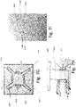
- a general schematic example of a custom mold 1110 is illustrated in Figure 7A , where sensors 1101, 1102 are placed on the custom mold.
- the arrangement of the sensors in a custom mold is described in the following in different examples as suggested in this part of the disclosure. The following will mainly focus on PPG sensors for use in custom molds, but other sensors could be contemplated.
- the shell material 1100 preferably is made from a transparent material, which especially allows light to pass in order to record the PPG signals from the detector.
- FIG. 7A Illustrated in Figure 7A is as mentioned a general custom mold 1110 shown.
- the custom mold 1110 comprises a faceplate 1103 which is configured with a plurality of the electrical components of the hearing aid.
- Figure 7B illustrates an example of an exploded view of a custom mold similar to Figure 7A , where it is seen that the custom mold comprises a receiver 1104 connected via electrical wires 1105 to a cover plate 1103 (also denoted a face plate throughout the disclosure).
- the custom mold 1110 is configured as a 3D printed shell based on an ear impression of a customer to which the hearing aid should be fitted.
- the shell of the custom mold i.e. the custom mold
- the custom mold may be configured with an inner core of the cover plate, wherein the inner core is configured as a hollow interior enabling placement of controlling components, e.g. sensor front-end or other sensors, such as accelerometer, and miscellaneous components (for e.g. capacitors) on the inside thereof.
- controlling components e.g. sensor front-end or other sensors, such as accelerometer, and miscellaneous components (for e.g. capacitors) on the inside thereof.
- a cover plate 1103 configured to be connected to a flexible PCB 1120 construction forms part of the custom mold.
- the PCB 1120 is wrapped around a protrusion extending from the cover plate 1103, and the PCB 1120 is configured to comprise at least one sensor, such as an LED emitter 1122 and a detector 1121.
- the inner core 1123 of the cover plate may be hollow enabling placement of controlling components, e.g. sensor front-end or other sensors, such as accelerometer, and miscellaneous components (for e.g. capacitors) on the inside.
- the components of the hollow inner side of the inner core 1123 may contain sensors or other electrical components connected to the same PCB as the LED emitter and the detector. In this way the whole volume of the cover plate is effectively utilized while the thickness of the cover plate is kept as small as possible to improve fit rate of customers.
- the cover plate 1103 comprises, in addition to the features already described in relation to the previous Figures 7C and 7D , a plurality of light blocking elements 1124 arranged at each corner of the cover plate.
- the light blocking elements 1124 in this way is configured to block the potential light path between the detector 1121 and the LED emitter 1122, which are as seen in the Figures arranged on perpendicular sides of the PCB 1120.
- the light blocking elements 1124 may protrude from the cover plate as the flex PCB is wrapped around the core as shown in Figure 7C and Figure 7E .
- the light blocking elements 124 may also be used to insert the PCB into the cover plate. This makes the assembly easier or could be used as snap feature to hold the PCB in place.
- the light blocking elements 124 is integrated into the inner core 1123. In this way, the light blocking elements 124 is protruding out from the inner core 1123 so as to ensure that the potential light path between the LED emitter 1122 and the detector 1121 is blocked.
- FIG. 7H Another possible solution to ensure that the detector is not influenced by direct light from the LED emitter is illustrated in a sketch in Figure 7H .
- the cover plate 1103 is configured with a protrusion comprising the PCB 1120 onto which a light emitter 1122 and a detector 1121 is arranged.
- the detector is surrounded by a substantially rigid tube made from a flexible polymer ensuring that the tube is blocking all light coming from an angle into the detector, and thereby protecting the detector from any noise signals.
- the custom mold may also be configured with light guides as an alternative, or supplement, to the previous presented solutions. That is, in Figure 7I , a custom mold is illustrated wherein the cover plate 1103 is configured with the previously described protrusion with a PCB to which the LED emitter 1121 and the detector (not illustrated) is attached.
- the LED emitter is configured to be in contact with a light guide 1128, which ensures that emitted light from the LED emitter 1122 is transmitted to the outside of the shell of the custom mold, without reflections inside the shell.
- These light guides 1128 may be 3D printed in the same material together with the shell.
- the PCB may form a protrusion of the cover plate. That is, the cover plate may be configured with a PCB extending therefrom.
- the construction thereof can be formed in some exemplary ways explained in the following, where generally the electrical components and sensors are placed on a PCB module, wherein the PCB module is arranged in the faceplate of the custom shell so as to protrude therefrom into the custom mold.
- the placement of the electrical components on a PCB module allows to use a generic PCB for different faceplate sizes, that are used for custom molds of different fitting levels. This way less parts have to be produced and assembly is simplified.
- the height of the PCB is thereby relevant, since it adds to the lengths of the custom mold.
- a longer custom mold is possibly more visible and therefore less discreet.
- the presented solutions minimize the height of the PCB, and comprises a PCB of the custom mold, which is configured with a bended portion so as to comprise an inner side and an outer side, wherein each of the outer sides of the PCB comprises at least one sensor configuration such as one LED emitter and one detector, and wherein the PCB is configured to be connected to the cover plate via an insertion area of the cover plate and insertion areas of the PCB.
- Figure 7J and Figure 7K illustrates two different views of a flexible PCB 1130, which is bended so as to comprise an inner side 1132 and an outer side 1131.
- different electrical components 1133 are arranged onto the PCB on both the inner side 1132 and the outer side 1131 of the PCB construction.
- the PCB is in an end facing away from a cover plate insertion area 1140 configured with a bended area 1136 from which two sides of the PCB extend to form the outer sides of the PCB.
- On each of the outer sides 1131 of the PCB at least one LED emitter 1134 and one detector 1135 is arranged as seen in Figure 7J and Figure 7K .
- a plurality of electrical components 1133 is arranged on both of the two outer sides 1131 of the PCB.
- the inner sides 1132 is configured to have electrical components 1133 arranged on the PCB. This optimizes the area at which electrical components can be arranged at PCB within a custom mold hearing aid.
- the flexible PCB 1130 is configured to be connected to the cover plate 1150 via an insertion area 1140 of the cover plate 1150. That is, as illustrated in Figure 7J and Figure 7K , the PCB is configured with two insertion areas 1136, 1137 formed on each of the two outer sides 1131 of the PCB in the end facing the cover plate 1150. As can be seen in Figure 7J as first insertion area 1136 is configured to inserted into a similar shaped groove 1141 in the cover plate 1150, whereas a second insertion area 1137 illustrated best in Figure 7K , is configured to be inserted to a second groove 1142 in the cover plate 1150. In this way it is ensured that the PCB can easily be fitted into the cover plate independent from the general shape of the custom mold.
- the PCB is attached to the cover plate by pushing the PCB into the insertion area and using an adhesive or similar material to fasten the PCB within the cover plate. This also accounts for the following described embodiments.
- FIG. 7M and Figure 7N A similar solution is illustrated in Figure 7M and Figure 7N .
- the PCB is configured with a larger bend area 1136 than in the previous described Figures 7J and Figure 7K .
- the PCB comprises as previously described a bended area 1136 from which two sides of the PCB extend to form the outer sides 1131 of the PCB.
- On each of the outer sides 1131 of the PCB at least one LED emitter 1134 and one detector 1135 is arranged as seen in Figure 7M and Figure 7N .
- a plurality of electrical components 1133 is arranged on both of the two outer sides 1131 of the PCB.
- this solution is configured to be pushed into the cover plate 1150 and fastened thereto by e.g. an adhesive material, as previously described.
- the PCB is also configured with a bended area 1136, but arranged to be placed in the cover plate 1150 with the bended area contacting a part of the cover plate 1150. That is, each of the two outer sides 1131, and the bended area 1136 (basically all of the edges of one side of the PCB) is in contact with the cover plate 1150. This results in an even further decrease in the height of the PCB as compared to the previous described solutions.
- the remaining features as previously described is the same and will not be explained again, but reference is made to the figures and the numbering previously described.
- the overall shape of the PCB is here generally U-like shaped.
- the PCB may be formed as a ring-shaped flexible PCB 1130.
- the LED emitter(s) and the photo detector(s) forming the PPG sensor 1137 are arranged on a ring-shaped flexible PCB 1130, which is made from a flat flexible PCB.
- the PCB gets pretensioned.
- the PCB gets affixed by pushing it into the custom shell. Due to the spring force of the PCB, the PCB will expand and push the LED emitter(s) and photodetector(s) onto the shells inner surface. This will ensure ideal light transmission properties through the shell and reduce skin reflection and direct light transmission.
- FIG 7R a solution is illustrated, where the PCB 1130 is substantially star shaped and placed in the cover plate of the shell.
- This type of star shaped PCB 1130 is made from a flat flexible PCB, where the LEDs 1134 and photo detectors 1135 are placed at the ends of the "star".
- the center 1139 of this star is connected to the cover plate (not illustrated) and may contain more electrical components.
- the LEDs and photo detector are again pressed to the inner surface of the shell as described before.
- Features in the shell may guide the 'arms' into the correct placement. They may be fixed into place by glue or other fixation material.
- Another solution is to provide a dome of the hearing aid with sensors, as described in relation to Figures 5A, 5B, 5C and Figures 6A, 6B and 6C .
- the dome comprises integrated sensors it is important that these sensors efficiently can communicate with the speaker unit to transfer information recorded by the sensors. That is, a PCB is normally not present in the dome, why any electrical communication with the remaining of the hearing aid needs to be via the speaker unit, where the electronic parts of the hearing aid in communication with other electronic parts of the hearing aid is located. Therefore, in sensor integrated domes, a solution for an efficient interface between the speaker unit and the dome is needed.
- such interface is achieved by a speaker unit configuration configured with speaker unit sensor electronics and a plurality of electrical connections at an acoustical interface of the speaker unit configuration, and wherein the dome is configured with dome electrical connections and a dome acoustical interface so as to allow electrical communication between one or more sensor configurations of the dome and the speaker unit when the speaker unit acoustical interface and the dome acoustical interface connects.
- the solution of providing the speaker unit (i.e. speaker unit configuration) with an electrical interface, more specifically to provide the snout of the speaker unit with an electrical interface, is illustrated in Figure 8 and will be described in further detail in the following. The described solution allows for users to swap out the domes without any knowledge about electronics i.e.
- exchanging domes will be identical to the current swap of domes.
- the solution will also allow for cheap electronics such as a NTC (resistive temperature sensor) or LED to be integrated into the dome, and disposed of, while the much more expensive driving/data collection circuit is integrated into the speaker unit and therefore not disposed of.
- NTC resistive temperature sensor
- LED light-sensitive diode
- printed electronics such as printed temperature sensors or photosensitive materials will require an interface like this.
- the speaker unit 1701 is configured with speaker unit sensor electronics 1704 and a plurality of electrical connections 1702 within an acoustical interface 1703 of the speaker unit 1700.
- the dome 1705 is configured with dome electrical connections 1706 and a dome acoustical interface 1707.
- the dome 1705 comprises at least one sensor, however two sensors 1708, 1709 is illustrated, which sensors 1708, 1709 is electrically connected to the electrical connections 1706 via an electrically conductive connection 1710 (illustrated with the broken line) integrated into the dome 1705.
- the electrical connections 1702 of the speaker unit 1701 and the electrical connections 1706 of the dome 1705 electrically engages and allows transfer of electrical information from the one or more sensors 1708, 1709 to the speaker unit sensor electronics 1704. In this way signal transfer from the sensors to the speaker unit is achieved while at the same time the dome is exchangeable.
- the suggested solution according to Figure 8 may of course include more or fewer electrical connections depending on requirements of the sensors included in the dome.
- the connections may transfer analog (e.g. electrical resistance or LED and photo detector currents) or digital (e.g. I2C, SPI or other communication) signals.
- the signals transferred from the dome to the speaker unit may be used/conditioned by electronics inside the ear and/or passed directly to the hearing instrument or electronics placed in between.
- the electrical connections of the dome may be provided by printing electrically conductive traces onto the dome. They may be printed on a flat surface and then grafted onto the dome, which will result in nice synergies with printed sensors such as core body temperature sensors printed onto the dome which will provide much higher quality temperature readings as they will be less sensitive to the ambient environment. Similarly, photo detectors printed onto the dome will allow for a much higher sensitivity increasing signal quality.
- Another similar solution to the above could be to stick conductive film/foil (e.g. copper foil) to the dome realizing the electrical traces and connection, while another implementation could be to mold in conductive rings and wire connections into the dome material.
- a solution presented in Figure 9 is to wrap a flexible printed circuit board 1402 around the receiver 1406.
- the flexible printed circuit board 1402 comprises at least one sensor, chosen as e.g. a PPG sensor having an LED emitter 1405 and photo detector 1404.
- the PPG sensor is arranged on the flexible printed circuit board 1402 in a manner where the LED emitter 1405 is placed to emit light onto the inside of a dome 1403. That is, the LED emitter 1405 is arranged on a first side 1406a of the receiver 1406, whereas the photodetector 1404 is arranged on a second side 1406b side of the receiver 1406, wherein the first and the second side is substantially perpendicular to each other.
- FIGs 9A and 9B Another possible solution, different from the flexible PCB formed around the receiver as just described, is to provide a substantially flat piece of PCB arranged on the top and/or bottom side of the receiver.
- a receiver 1801 is illustrated as seen from the front.
- the two sides of the receiver together forming the height of the receiver when seen from the front, comprises in on case shown in Figure 9A , a PCB 1805 in both the top and bottom of the receiver.
- Each of the PCB's 1805 comprises an LED emitter 1803 configured to emit light and a detector 1802 configured to record reflections from the tissue caused by the emitted light.
- the detector 1802 and the LED emitter 1803 is separated by a light blocker, so as to avoid a direct light path from the LED emitter to the photo detector.
- FIG 9B a similar solution is illustrated. However, in this case only one LED emitter 1803a and one detector 1802a is arranged in connection with a bottom and top, respectively, of the receiver 1801. Each of the LED emitter 1803a and the detector 1802a is arranged on a PCB 1805 as previously described.
- FIG 9C as solution of a receiver 1802 comprising one or more sensors is illustrated.
- the receiver 1802 is seen with the front facing towards the arrow and the back of the receiver the opposite end.
- a sensor configuration similar to the one described in relation to Figure 9A .
- the detector 1802 is arranged on the flat PCB 1805 together with the LED emitter 1803. Such configuration is arranged on two sides of the receiver 1802 as illustrated.
- the detector 1802 and the LED emitter 1803 is separated by a light blocker as previously described in relation to Figure 9A .
- the receiver of a RITE style hearing aid is configured with a speaker housing.
- the construction of the housing so as to allow the sensors to sufficiently and effectively transmit and receive the signals needed for recording of biometrical data. Therefore, the construction of the speaker housing containing the receiver and the electrical components thereof, including the sensors has also been considered.
- the receiver housing i.e. the speaker casing
- the receiver housing is made from injection molded plastic assembled around the receiver and electronics, where the injection molded plastic comprises integrated light blocking features between LED and photo detector.
- the receiver and the electronics could be over molded with transparent silicone, epoxy or other material.
- transparent silicone, epoxy or other material By using a transparent material like transparent epoxy, the PPG sensor components (i.e. the LED emitter and the detector) can be over molded and shine directly through the material. This ensures a compact design of the speaker unit.
- Another example is provided by over molding with a light absorbing material.
- the receiver and electronics are over molded, while the LEDs and photodetectors are left free.
- the light absorbing material is acting as blocking feature between the sensor components.
- the speaker unit i.e. the housing containing the receive
- the protrusion generally comprises the sensor components as illustrated and explained in the following for each of the Figures.
- the protrusion 1810 may be arranged on the top of the speaker unit 1801.
- a flexible PCB (not illustrated) may be wrapped around the protrusion allowing for a high amount of PCB real-estate at a low receiver area.
- the solution also allow the optical components, such as the LED emitter 1803 and the detector 1802 to be placed at an angle to each other to reduce direct surface reflection, which would allow light to pass directly from the LED emitter 1803 to detector 1802 without entering the tissue (thereby not providing relevant signal).
- the construction places the optical components closer to the skin, which further decreases skin reflection and potentially increases signal quality due to more light entering the tissue (or at least at a more controlled location).
- the construction aims to utilize as much of the volume inside the ear as possible taking special consideration to the oval nature of the ear canal which allows for more build height having little room to increase in width without compromising fit-rate (significantly).
- the protrusion also allows for a LED emitter or detector to be placed facing inwards allowing for additional optical paths.
- the protrusion 1810 may also be arranged on the bottom instead of the top of the speaker unit 1801.
- a protrusion 1810 may be arranged on both the top and bottom of the speaker unit 1801. Having the protrusion 1810 in both the top and bottom creates a more symmetrical solution, which ensures a larger useable PCB area and freedom in component placement, while reducing skin reflection. This solution yields a more pronounced oval shape, which may fit more users than a single-side larger extrusion and conform better to the oval nature of the canal, thereby maximizing the ear canal volume utilization.
- the speaker unit 1801 comprises a protrusion part 1810, which is configured with a folded flexible PCB 1805, this to utilize the volume and stacking height available inside the ear while providing an optimized PCB component area (i.e. the area at which electrical components can be arranged on the PCB).
- the example of Figure 9F utilizes the volume of the protrusion for placement of components, thereby allowing for much more electronics packed in the same volume.
- the PCB may use combinations of the solutions described above e.g. using a protrusion for support or having parts of the PCB wrapped around the receiver.
- a flab may be folded in front (or a side-fire LED) to allow an emitter to shine inwards, or a flap parallel to the receiver making connections to the RITE-wire or receiver easier.
- a flab may be folded in front (or a side-fire LED) to allow an emitter to shine inwards, or a flap parallel to the receiver making connections to the RITE-wire or receiver easier.
- the sensors especially a PPG sensor is considered in a behind the ear hearing aid (i.e. a BTE type hearing aid)
- a BTE type hearing aid comprising PPG sensors
- Figure 15 An example of a BTE type hearing aid comprising PPG sensors is illustrated in Figure 15 .
- the sensors When having a sensor, such as a PPG sensor in a BTE style hearing aid, the normal positioning of the LED transmitter and detector is on the axis of symmetry of the BTE hearing aid - this to achieve same performance on both ears when wearing hearing aids on both ears.
- the disadvantage is however that the sensors will have equal sensitivity both towards the pinna and the skull which may not be desirable.
- the signal may be stronger from the skull than from the pinna or vice versa. In the same manner the noise may be stronger from one side or the other.
- the Left/Right information entered during fitting is used to select which side in the instrument the detector should be (most) active towards.
- the detector sensitivity direction could also be based on an estimated signal to noise ratio.
- the transmitter sensitivity direction could also be based on an estimated signal to noise ratio.
- electrophysiological signals like, electroencephalogram, electrocardiogram, electrooculogram, and skin conductance can be measured from within the ear cavity by attaching electrodes to the parts of the ear canal, in a particular configuration and in a particular location in the ear cavity.
- electrodes a compromise needs to be made when deciding key parameters for the signal of interest. These include but are not limited to signal preconditioning, hardware bandwidth, amplification strategy, electrode location, among others. Accordingly, it is necessary to have a system that can dynamically adjust these parameters in order to obtain the optimal configuration mode for each electrophysiological signal.
- a signal handling solution where an electrode switchboard 2601 creating two or more electrode configurations by combining the available electrodes into different groups or one single electrode, is considered.
- the electrode switchboard 2601 is in communication with a pre-amplifier, which at an pre-amplification stage 2602 is configured for conditioning the recorded electrode signals before amplification.
- the pre-amplifier 2602 is in electrical communication with an amplifier switchboard 2603 that is configured to interphase the output of the electrode switchboard to two different instrumentation amplifiers.
- the two instrumentation amplifiers is configured with one for dielectric or contact electrode input 2604 and one for capacitive electrode inputs 2605, and is further in electrical communication with a signal analyser 2606 that is configured to evaluate the noise level, signal amplitude and electrode contact from each possible configuration of the electrodes and as an output choose the optimal configuration for measuring in a given scenario (i.e., feedback loop to electrode switchboard and amplifier switchboard to optimize signal quality).
- a signal analyser 2606 that is configured to evaluate the noise level, signal amplitude and electrode contact from each possible configuration of the electrodes and as an output choose the optimal configuration for measuring in a given scenario (i.e., feedback loop to electrode switchboard and amplifier switchboard to optimize signal quality).
- This general setup is illustrated in Figure 10 , in a schematic setup.
- the electrodes or other types of sensors
- these electrodes can also be arranged within the ear canal in close contact to the skin of the ear canal via the hearing aid parts positioned therein.
- An application considered when using a PPG sensor in a hearing aid is for example to use the PPG sensor recordings to evaluate if a hearing aid is positioned on the ear or not. This is used to for example be able to turn off the hearing aid, when it is not being worn, and further to collect information on how the hearing instrument is being used.
- the PPG sensor may be used as an on-ear wear detector, as it has been found that the mean value ( ⁇ ) and standard deviation (SD) of a photoplethysmography (PPG) sensor are significantly different when the sensor is placed on human skin compared to a table/free space. These values can therefore be used to give an estimate of whether the sensor is in the ear or not.
- the algorithm may be configured to detect a heart rate (HR). If no HR is found, the sensor is evaluated to be outside the ear and the opposite if the HR is found. Thus, when placing a PPG sensor in the hearing instrument these measures can be used to detect wearing of the HI. The process is shown in Figure 11 .
- the mean value ( ⁇ ) is within a set threshold range (i.e. ⁇ >ThLow & ( ⁇ ThHigh) then it is evaluated in the standard deviation (SD) is within a set threshold range (i.e. SD>ThLow & SD ⁇ ThHigh) and if this is true the heart rate (HR) may be detected. If a heart rate is detected, then it is evaluated that the hearing aid is in the ear, whereas if the heart rate is not detected, or the mean value ( ⁇ ) or the standard deviation (SD) is out of the set threshold ranges, then the hearing aid is evaluated not to be in the ear.
- a set threshold range i.e. ⁇ >ThLow & ( ⁇ ThHigh
- thermomedical sensors such as temperature sensors may be included in the process as well, when mounted in a hearing to improve the estimate of wear detection.
- This process is illustrated in Figure 12 .
- the process is as previously described in relation to Figure 11 in addition to the step that when a heart rate is detected a further step of controlling the temperature by a temperature sensor is included.
- the hearing aid is deemed as being placed in or at the ear.
- the hearing aid is evaluated not to be positioned in the ear.
- the temperature sensor a more robust wear detection is achieved, since it relies on two biometrical parameters for evaluating if the hearing aid is worn.
- the placement of sensors within the ear allows for different biometrical measurement of a person wearing a hearing aid.
- noise components from the sensors which preferably also should be avoided is motion artifacts and other noise components.
- a PPG sensor it has been considered how to evaluate the signal quality of a sensor, especially for the following described example, a PPG sensor.
- a multi-channel PPG sensor for estimating a physiological parameter based on signal quality index (SQI) estimation.
- Signal quality estimation provides a measurement of how confident a signal reading can be considered, and when using a multichannel system, one is able to choose which of the multichannel signals to use and react to. This reduces the false alarm rates / false predictions of the measurements performed by the sensor.
- a multi-path PPG system design has advantages over single channel PPG systems. It is possible to get redundant PPG data, thus enabling more noise supressed data which are crucial for any PPG derived physiological parameter estimation.
- a four-channel PPG signal is used for the hearing aid instrument as an example.
- the SQI may be configured on the basis of at least one of three different methods: Dynamic Time Warping (DTW), Direct matching and/or linear resampling. The three methods are compared to a template which is generated from the PPG beats.
- DTW Dynamic Time Warping
- Direct matching Direct matching
- linear resampling The three methods are compared to a template which is generated from the PPG beats.
- Figure 13 show the process of finding the optimal signal channel to be used for the biometrical measures. That is, the recorded data 2900 from the sensor signal (in this case a PPG sensor), is firstly preprocessed 2901. In the preprocessing step 2901 a band pass filter, which passes frequencies between [0.5 10] Hz, is implemented. The signals are then normalized to the [0.05, 0.95] quantiles, this is done in order to make the signal less noise prone and make it easier and more consistent to find the PPG peaks which is the final step in the pre-processing step.
- a band pass filter which passes frequencies between [0.5 10] Hz
- DTW Dynamic Time Warping
- DTW allows for nonlinear and nonstationary changes in the beat morphology, and makes it possible to correlate each beat with the template, see step 2903 in Figure 13 . Accordingly, DTW finds the optimal path in order to minimize the cumulative distance of the path, see figure 13A .
- Figure 13A (a) illustrates a PPG template (T, bold) and a recorded PPG beat (B, Normal line).
- Figure 13A (b) illustrates the alignment between the template (T) and the recorded beat (B) whereby a warping matrix can be constructed to find the optimal path minizing the distance between the recorded beat (B) and the template (T).
- Figure 13A (c) illustrated the alignment flow between the template (T) and the recorded beat (B).
- the direct matching method is in more detail, done by selecting the sampling point series of each beat within the 30 second window, starting at the onset of the beat and ending at the length of the template. Then calculating the correlation coefficient with the template as the direct matching.
- Another method i.e. Linear resampling is done by selecting each beat between two PPG onsets and linearly stretch (stretch or compress depending on if the beat length is longer or shorter than the template, respectively). Then calculate the correlation coefficient as the linear resampling.
- Figure 13C illustrates examples of an SQI index calculated from a signal captured in different photo detectors (PD) from two LEDs (in a 2 LED+ 2 PD setting). It can be seen from the figure that, data at PD1 exhibits higher SQI than the PD2 which is more corrupted by noise.
- a solution to this is given in this disclosure by utilizing a motion compensation algorithm based on Constrained Independent Component Analysis (cICA).
- cICA Constrained Independent Component Analysis
- Figure 13D illustrates a shaded area 2905 of the signal, where motion is present.
- the algorithm uses a template 2906 calculated from the cICA and uses that template to motion compensate the PPG signal, resulting in the signal 2907 of the Figure.
- the motion component 2908 can be found and compensated for in the original PPG signal.
- the motion artifact cannot be compensated for by using the just described algorithm, and therefore other solutions have been suggested in this disclosure.
- FIG. 13E a model for PPG motion compensation based on the previously described SQI is presented.
- the motion compensation algorithm is run on the segment of data having a moderate SQI, below which the data is completely unusable and therefore discarded as shown is Figure 13E .
- the PPG data is sent into the preprocessing step as previously described in relation to Figure 13 .
- the SQI as also previously described is then calculated and the SQI's are divided into three thresholds, i.e. motion compensation necessary (50 ⁇ SQI ⁇ 80), no motion compensation needed (80 ⁇ SQI), discard signal (50 ⁇ SQI).
- the SQI signals needing motion compensation is run through a motion compensation algorithm as described in relation to Figure 13D , whereas the other signals are discarded or used direction as a clean signal which can be directly used.
- the motion compensation is thus calculated on already SQI evaluated signals, i.e. the signals that need motion compensation based on the SQI classification, is given a motion compensation and then compared to the original signals, thereby removing the motion artifact from the signal.
- An example is illustrated in Figure 13F , where it is seen that the motion corrupted data (i.e. a signal having an SQI between 50 and 80)) is run through the motion compensation calculation whereby the motion component can be identified and removed from the signal.
- Figure 13F illustrated a part of the data, based on the interval [7500 8500], as being discarded due to poor SQI ( ⁇ 50) to ensure the highest quality data to be used for any potential physiological marker estimation.
- the remaining of the data from the PPG sensor was motion compensated as described in the framework of Figure 13F .
- the suggestion is to utilize not only a PPG sensor but also an EEG sensor (or similar sensor).
- the hearing aid is configured to transmit biometrical sensor data to the auxiliary device via the communication interface, and wherein the auxiliary device is configured to process said biometrical sensor data in a signal processor of the auxiliary device and to transmit an output from said data processing back to said hearing aid.
- the biometrical sensor data transmitted to the auxiliary device is transmitted to said signal processor of the auxiliary device, wherein the signal processor is configured to perform a pre-processing step of the biometrical data and calculate a signal quality index on the pre-processed data to evaluate the biometrical signal data with the highest quality, and wherein the biometrical signal data is motion compensated prior to calculating the signal quality index.
- the signal processor is configured to perform a pre-processing step of the biometrical data and calculate a signal quality index on the pre-processed data to evaluate the biometrical signal data with the highest quality
- the biometrical signal data is motion compensated prior to calculating the signal quality index.
- FIG. 14A and Figure 14B show typical motion artefact independently acquired from EarEEG and PPG signals, respectively, inside the ear canal.
- Motion in the EarEEG can be characterized by capturing eye movement, i.e. measuring the EOG signal.
- the EarEEG level changes with saccade eye movement proportionally.
- an EarEEG signal is prone to slow drift which is removed by a high pass filter at a preprocessing step.
- Normal head rotation induce vexibulo ocular reflex in the EarEEG which is basically the fact that eye rotates faster than the head, essentially EOG signal.
- This specific phenomenon can be used to flag the PPG data during head rotation and by identifying the flagged data, special filter / artefact compensator can be designed.
- one way to characterize the motion in the EEG is by utilizing an Extended Kalman filter.
- a random motion in the data will exhibit higher residual in the measurement update step.
- the residual value over a certain threshold would flag the data as motion corrupted.
- the EarEEG is measured and the PPG signal is measured.
- the EarEEG signal is run through a motion detector, where motion is detected as described above. If motion is detected, the detected motion is used in the PPG data before calculating the previously described SQI. If motion is not detected the data from the PPG can be seen as "clean signal” and the SQI is calculated based on the "clean signal". In both cases a motion compensated PPG signal can be calculated.
- the motion detector used on the EEG signal is in more detail illustrated in Figure 30D, where it is seen that the EEG signal is input to a motion detection block, where the signal is processed by a Kalman filter state with constant velocity. The residual is found and if the residual is above a set threshold motion is detected, and if not, motion is not detected. The outcome, motion/no motion is input to evaluate the PPG signal as previously described.
- the PPG sensor has also been considered to be utilized for measuring the amount of light a person wearing the hearing aid is exposed to. That is, in one embodiment, the hearing aid is configured with a light sensor, for example a PPG sensor, positioned at an environmental facing surface of the hearing aid. In this way it may be possible to e.g. detect light to evaluate risk of epileptic seizures, securing a good sleep, that is to assess if the type of light exposure is the right color and intensity at the right time of day, decreasing risk of sun-burning by comparing light exposure to local UV-index and/or asses if the user gets enough light exposure during the day (vitamin D).
- a light sensor for example a PPG sensor
Landscapes
- Health & Medical Sciences (AREA)
- Engineering & Computer Science (AREA)
- Life Sciences & Earth Sciences (AREA)
- General Health & Medical Sciences (AREA)
- Physics & Mathematics (AREA)
- Otolaryngology (AREA)
- Signal Processing (AREA)
- Acoustics & Sound (AREA)
- Neurosurgery (AREA)
- Public Health (AREA)
- Biomedical Technology (AREA)
- Surgery (AREA)
- Animal Behavior & Ethology (AREA)
- Medical Informatics (AREA)
- Heart & Thoracic Surgery (AREA)
- Veterinary Medicine (AREA)
- Biophysics (AREA)
- Pathology (AREA)
- Molecular Biology (AREA)
- Cardiology (AREA)
- Computer Networks & Wireless Communication (AREA)
- Physiology (AREA)
- Dermatology (AREA)
- Manufacturing & Machinery (AREA)
- Psychiatry (AREA)
- Psychology (AREA)
- Radiology & Medical Imaging (AREA)
- Nuclear Medicine, Radiotherapy & Molecular Imaging (AREA)
- Measurement Of The Respiration, Hearing Ability, Form, And Blood Characteristics Of Living Organisms (AREA)
Applications Claiming Priority (1)
| Application Number | Priority Date | Filing Date | Title |
|---|---|---|---|
| EP21150674 | 2021-01-08 |
Publications (1)
| Publication Number | Publication Date |
|---|---|
| EP4027658A1 true EP4027658A1 (fr) | 2022-07-13 |
Family
ID=74125067
Family Applications (1)
| Application Number | Title | Priority Date | Filing Date |
|---|---|---|---|
| EP21214059.4A Pending EP4027658A1 (fr) | 2021-01-08 | 2021-12-13 | Prothèse auditive comprenant un ou plusieurs capteurs pour mesures biométriques |
Country Status (2)
| Country | Link |
|---|---|
| EP (1) | EP4027658A1 (fr) |
| CN (1) | CN115103282A (fr) |
Cited By (1)
| Publication number | Priority date | Publication date | Assignee | Title |
|---|---|---|---|---|
| US20220174432A1 (en) * | 2019-03-26 | 2022-06-02 | Sonova Ag | Custom hearing device equipped with optical sensors for biometrical sensing |
Citations (3)
| Publication number | Priority date | Publication date | Assignee | Title |
|---|---|---|---|---|
| US20170311097A1 (en) * | 2016-04-26 | 2017-10-26 | Oticon A/S | Hearing device comprising electrodes for picking up a physiological response |
| US20190253793A1 (en) * | 2018-02-13 | 2019-08-15 | Oticon A/S | In-the-ear hearing aid device, a hearing aid, and an electro-acoustic transducer |
| WO2019232042A1 (fr) * | 2018-05-31 | 2019-12-05 | Valencell, Inc. | Ensemble tête de capteur biométrique |
-
2021
- 2021-12-13 EP EP21214059.4A patent/EP4027658A1/fr active Pending
-
2022
- 2022-01-10 CN CN202210023269.6A patent/CN115103282A/zh active Pending
Patent Citations (3)
| Publication number | Priority date | Publication date | Assignee | Title |
|---|---|---|---|---|
| US20170311097A1 (en) * | 2016-04-26 | 2017-10-26 | Oticon A/S | Hearing device comprising electrodes for picking up a physiological response |
| US20190253793A1 (en) * | 2018-02-13 | 2019-08-15 | Oticon A/S | In-the-ear hearing aid device, a hearing aid, and an electro-acoustic transducer |
| WO2019232042A1 (fr) * | 2018-05-31 | 2019-12-05 | Valencell, Inc. | Ensemble tête de capteur biométrique |
Cited By (1)
| Publication number | Priority date | Publication date | Assignee | Title |
|---|---|---|---|---|
| US20220174432A1 (en) * | 2019-03-26 | 2022-06-02 | Sonova Ag | Custom hearing device equipped with optical sensors for biometrical sensing |
Also Published As
| Publication number | Publication date |
|---|---|
| CN115103282A (zh) | 2022-09-23 |
| US20220218281A1 (en) | 2022-07-14 |
Similar Documents
| Publication | Publication Date | Title |
|---|---|---|
| CN110166916B (zh) | 耳内式助听器装置、助听器及电声变换器 | |
| US11583215B2 (en) | Generic ear device with electrodes | |
| Looney et al. | The in-the-ear recording concept: User-centered and wearable brain monitoring | |
| US20190380597A1 (en) | Device for monitoring activities of daily living and physiological parameters to determine a condition and diagnosis of the human brain and body | |
| US20220015703A1 (en) | Modular auricular sensing system | |
| EP3883260B1 (fr) | Dispositif d'aide auditive pour fournir des informations physiologiques et son procédé de fonctionnement | |
| US20220141601A1 (en) | Portable system for gathering and processing data from eeg, eog, and/or imaging sensors | |
| KR20180056671A (ko) | 생체 전기 신호를 검출하기 위한 외이도 플러그 | |
| US20200275856A1 (en) | An intra- and circum-aural eeg brain computer interface | |
| US20240122526A1 (en) | Minimal material ear sensor system | |
| EP4027658A1 (fr) | Prothèse auditive comprenant un ou plusieurs capteurs pour mesures biométriques | |
| JP7282044B2 (ja) | 生体認証データを検出するセンサを有する眼鏡 | |
| Kaongoen et al. | The future of wearable EEG: A review of ear-EEG technology and its applications | |
| US11998354B2 (en) | Hearing aid comprising one or more sensors for biometrical measurements | |
| US20230148963A1 (en) | Multi-body earpiece | |
| US20240015450A1 (en) | Method of separating ear canal wall movement information from sensor data generated in a hearing device | |
| US11863937B2 (en) | Binaural hearing system for providing sensor data indicative of a physiological property, and method of its operation | |
| US20220218235A1 (en) | Detection of conditions using ear-wearable devices | |
| JP2024035728A (ja) | 生体情報計測装置 | |
| Paul | In-Ear Electrophysiology for Unobtrusive Auditory Brain-Machine Interfaces |
Legal Events
| Date | Code | Title | Description |
|---|---|---|---|
| PUAI | Public reference made under article 153(3) epc to a published international application that has entered the european phase |
Free format text: ORIGINAL CODE: 0009012 |
|
| STAA | Information on the status of an ep patent application or granted ep patent |
Free format text: STATUS: THE APPLICATION HAS BEEN PUBLISHED |
|
| AK | Designated contracting states |
Kind code of ref document: A1 Designated state(s): AL AT BE BG CH CY CZ DE DK EE ES FI FR GB GR HR HU IE IS IT LI LT LU LV MC MK MT NL NO PL PT RO RS SE SI SK SM TR |
|
| STAA | Information on the status of an ep patent application or granted ep patent |
Free format text: STATUS: REQUEST FOR EXAMINATION WAS MADE |
|
| 17P | Request for examination filed |
Effective date: 20230113 |
|
| RBV | Designated contracting states (corrected) |
Designated state(s): AL AT BE BG CH CY CZ DE DK EE ES FI FR GB GR HR HU IE IS IT LI LT LU LV MC MK MT NL NO PL PT RO RS SE SI SK SM TR |
|
| GRAP | Despatch of communication of intention to grant a patent |
Free format text: ORIGINAL CODE: EPIDOSNIGR1 |
|
| STAA | Information on the status of an ep patent application or granted ep patent |
Free format text: STATUS: GRANT OF PATENT IS INTENDED |