EP4027497A1 - Generator and tire condition monitoring device - Google Patents
Generator and tire condition monitoring device Download PDFInfo
- Publication number
- EP4027497A1 EP4027497A1 EP21863886.4A EP21863886A EP4027497A1 EP 4027497 A1 EP4027497 A1 EP 4027497A1 EP 21863886 A EP21863886 A EP 21863886A EP 4027497 A1 EP4027497 A1 EP 4027497A1
- Authority
- EP
- European Patent Office
- Prior art keywords
- container portion
- rotor
- power generator
- stator
- fixed
- Prior art date
- Legal status (The legal status is an assumption and is not a legal conclusion. Google has not performed a legal analysis and makes no representation as to the accuracy of the status listed.)
- Withdrawn
Links
- 238000012806 monitoring device Methods 0.000 title claims description 8
- 239000007788 liquid Substances 0.000 claims abstract description 40
- 230000002093 peripheral effect Effects 0.000 claims description 14
- 238000004891 communication Methods 0.000 claims description 5
- 238000012544 monitoring process Methods 0.000 claims description 4
- 230000035515 penetration Effects 0.000 claims 3
- 238000010248 power generation Methods 0.000 description 5
- 238000005516 engineering process Methods 0.000 description 3
- 230000002528 anti-freeze Effects 0.000 description 1
- 238000001514 detection method Methods 0.000 description 1
- 230000006866 deterioration Effects 0.000 description 1
- 230000000694 effects Effects 0.000 description 1
- 239000012530 fluid Substances 0.000 description 1
- 239000007787 solid Substances 0.000 description 1
Images






Classifications
-
- B—PERFORMING OPERATIONS; TRANSPORTING
- B60—VEHICLES IN GENERAL
- B60C—VEHICLE TYRES; TYRE INFLATION; TYRE CHANGING; CONNECTING VALVES TO INFLATABLE ELASTIC BODIES IN GENERAL; DEVICES OR ARRANGEMENTS RELATED TO TYRES
- B60C23/00—Devices for measuring, signalling, controlling, or distributing tyre pressure or temperature, specially adapted for mounting on vehicles; Arrangement of tyre inflating devices on vehicles, e.g. of pumps or of tanks; Tyre cooling arrangements
- B60C23/02—Signalling devices actuated by tyre pressure
- B60C23/04—Signalling devices actuated by tyre pressure mounted on the wheel or tyre
- B60C23/0408—Signalling devices actuated by tyre pressure mounted on the wheel or tyre transmitting the signals by non-mechanical means from the wheel or tyre to a vehicle body mounted receiver
- B60C23/041—Means for supplying power to the signal- transmitting means on the wheel
-
- B—PERFORMING OPERATIONS; TRANSPORTING
- B60—VEHICLES IN GENERAL
- B60C—VEHICLE TYRES; TYRE INFLATION; TYRE CHANGING; CONNECTING VALVES TO INFLATABLE ELASTIC BODIES IN GENERAL; DEVICES OR ARRANGEMENTS RELATED TO TYRES
- B60C23/00—Devices for measuring, signalling, controlling, or distributing tyre pressure or temperature, specially adapted for mounting on vehicles; Arrangement of tyre inflating devices on vehicles, e.g. of pumps or of tanks; Tyre cooling arrangements
- B60C23/02—Signalling devices actuated by tyre pressure
- B60C23/04—Signalling devices actuated by tyre pressure mounted on the wheel or tyre
- B60C23/0408—Signalling devices actuated by tyre pressure mounted on the wheel or tyre transmitting the signals by non-mechanical means from the wheel or tyre to a vehicle body mounted receiver
- B60C23/041—Means for supplying power to the signal- transmitting means on the wheel
- B60C23/0411—Piezoelectric generators
-
- B—PERFORMING OPERATIONS; TRANSPORTING
- B60—VEHICLES IN GENERAL
- B60C—VEHICLE TYRES; TYRE INFLATION; TYRE CHANGING; CONNECTING VALVES TO INFLATABLE ELASTIC BODIES IN GENERAL; DEVICES OR ARRANGEMENTS RELATED TO TYRES
- B60C23/00—Devices for measuring, signalling, controlling, or distributing tyre pressure or temperature, specially adapted for mounting on vehicles; Arrangement of tyre inflating devices on vehicles, e.g. of pumps or of tanks; Tyre cooling arrangements
- B60C23/02—Signalling devices actuated by tyre pressure
- B60C23/04—Signalling devices actuated by tyre pressure mounted on the wheel or tyre
- B60C23/0408—Signalling devices actuated by tyre pressure mounted on the wheel or tyre transmitting the signals by non-mechanical means from the wheel or tyre to a vehicle body mounted receiver
- B60C23/0422—Signalling devices actuated by tyre pressure mounted on the wheel or tyre transmitting the signals by non-mechanical means from the wheel or tyre to a vehicle body mounted receiver characterised by the type of signal transmission means
- B60C23/0433—Radio signals
-
- B—PERFORMING OPERATIONS; TRANSPORTING
- B60—VEHICLES IN GENERAL
- B60C—VEHICLE TYRES; TYRE INFLATION; TYRE CHANGING; CONNECTING VALVES TO INFLATABLE ELASTIC BODIES IN GENERAL; DEVICES OR ARRANGEMENTS RELATED TO TYRES
- B60C23/00—Devices for measuring, signalling, controlling, or distributing tyre pressure or temperature, specially adapted for mounting on vehicles; Arrangement of tyre inflating devices on vehicles, e.g. of pumps or of tanks; Tyre cooling arrangements
- B60C23/02—Signalling devices actuated by tyre pressure
- B60C23/04—Signalling devices actuated by tyre pressure mounted on the wheel or tyre
- B60C23/0408—Signalling devices actuated by tyre pressure mounted on the wheel or tyre transmitting the signals by non-mechanical means from the wheel or tyre to a vehicle body mounted receiver
- B60C23/0422—Signalling devices actuated by tyre pressure mounted on the wheel or tyre transmitting the signals by non-mechanical means from the wheel or tyre to a vehicle body mounted receiver characterised by the type of signal transmission means
- B60C23/0433—Radio signals
- B60C23/0447—Wheel or tyre mounted circuits
-
- B—PERFORMING OPERATIONS; TRANSPORTING
- B60—VEHICLES IN GENERAL
- B60C—VEHICLE TYRES; TYRE INFLATION; TYRE CHANGING; CONNECTING VALVES TO INFLATABLE ELASTIC BODIES IN GENERAL; DEVICES OR ARRANGEMENTS RELATED TO TYRES
- B60C23/00—Devices for measuring, signalling, controlling, or distributing tyre pressure or temperature, specially adapted for mounting on vehicles; Arrangement of tyre inflating devices on vehicles, e.g. of pumps or of tanks; Tyre cooling arrangements
- B60C23/20—Devices for measuring or signalling tyre temperature only
-
- G—PHYSICS
- G01—MEASURING; TESTING
- G01M—TESTING STATIC OR DYNAMIC BALANCE OF MACHINES OR STRUCTURES; TESTING OF STRUCTURES OR APPARATUS, NOT OTHERWISE PROVIDED FOR
- G01M17/00—Testing of vehicles
- G01M17/007—Wheeled or endless-tracked vehicles
- G01M17/02—Tyres
-
- H—ELECTRICITY
- H02—GENERATION; CONVERSION OR DISTRIBUTION OF ELECTRIC POWER
- H02K—DYNAMO-ELECTRIC MACHINES
- H02K7/00—Arrangements for handling mechanical energy structurally associated with dynamo-electric machines, e.g. structural association with mechanical driving motors or auxiliary dynamo-electric machines
- H02K7/02—Additional mass for increasing inertia, e.g. flywheels
-
- H—ELECTRICITY
- H02—GENERATION; CONVERSION OR DISTRIBUTION OF ELECTRIC POWER
- H02K—DYNAMO-ELECTRIC MACHINES
- H02K7/00—Arrangements for handling mechanical energy structurally associated with dynamo-electric machines, e.g. structural association with mechanical driving motors or auxiliary dynamo-electric machines
- H02K7/18—Structural association of electric generators with mechanical driving motors, e.g. with turbines
- H02K7/1807—Rotary generators
- H02K7/1846—Rotary generators structurally associated with wheels or associated parts
Definitions
- the present disclosure relates to a power generator and a tire state monitoring device including the power generator.
- Patent Document 1 a technology for attaching an electric device and a power source thereof to a wheel has been known (see Patent Document 1, for example).
- Patent document 1 WO 2019/194303 A (Paragraphs [0024], [0026], [0027], etc.)
- a power generator made to solve the above problem includes: a stator fixed to a wheel; and a rotor disposed coaxially with the wheel and rotatably supported by the stator, and the power generator generates electric power by relative rotation between the stator and the rotor, and supplies the electric power to an electric device attached to the wheel.
- the power generator further includes: a blade portion fixed to the rotor; a container portion that is fixed to one of the rotor and the stator and houses the blade portion; and a liquid which is contained in the container portion in an amount smaller than a volume of the container portion and in which at least a part of the blade portion is immersed.
- Figs. 1 and 2 illustrate a power generator 10 of the present embodiment.
- the power generator 10 is assembled on a wheel 81 of a vehicle 80.
- the power generator 10 includes a motor including a stator 20 (see Fig. 4(B) ) fixed to the wheel 81 and a rotor 30 rotatably supported by the stator 20.
- the power generator 10 can generate electric power by relative rotation between the stator 20 and the rotor 30.
- the stator 20 is fixed to, for example, an outer side part of a hub 84, of the wheel 81 fixed to the wheel shaft 83, in a vehicle width direction (see Fig. 2 ), and is disposed so as to surround the rotor 30.
- the rotor 30 has, for example, a columnar shape, is supported by the stator 20 via a bearing (not shown), and is disposed coaxially with the wheel 81 (with the wheel shaft 83).
- Examples of the motor constituting the power generator 10 include a stepping motor without being limited thereto, and a motor suitable for various types of power generation can be used.
- a center shaft 31 protrudes coaxially with the wheel 81 from the center of the surface, of the rotor 30, directed outward in the vehicle width direction.
- a container portion 40 is fixed to a tip part of the center shaft 31.
- the container portion 40 has a hollow disk shape, and the center of the container portion 40 is fixed to the center shaft 31.
- the container portion 40 can rotate integrally with the center shaft 31 (that is, with the rotor 30).
- the container portion 40 includes: a base wall 41 having a circular plate shape whose center is fixed to the center shaft 31; a peripheral wall 42 protruding from an outer edge part of the base wall 41 to a side away from the rotor 30; and a tip wall 43 closing the peripheral wall 42 from the opposite side to the rotor 30.
- An enclosed space is formed in a portion surrounded by the base wall 41, the peripheral wall 42, and the tip wall 43.
- liquid L is stored in the enclosed space of the container portion 40.
- the liquid L is stored in the container portion 40 in an amount smaller than a volume of the container portion 40, and in the example of the present embodiment, the amount of the liquid L is less than half the volume of the container portion 40 so that a liquid level of the liquid L is lower than a rotation center of the wheel 81 when the container portion 40 is in a stationary state.
- the liquid L include antifreeze fluid.
- the blade portions 50 fixed to the rotor 30 are housed in the container portion 40.
- the blade portions 50 are disposed so as to be at least partially immersed in the liquid L.
- blade portions 50 protrude from an inner peripheral surface of the peripheral wall 42 of the container portion 40 toward the center (rotation center) of the container portion 40.
- a plurality of (for example, eight) the blade portions 50 is provided, and is arranged at equal intervals in a circumferential direction of the container portion 40, for example.
- some blade portions 50 among the blade portions 50 are entirely immersed in the liquid L when the rotor 30 is in a stationary state.
- the blade portions 50 are each formed in an elongated isosceles triangle shape tapered toward the center of the container portion 40 when viewed in the direction toward the central axis of the rotor 30.
- the blade portions 50 are integrally formed with the base wall 41 and the peripheral wall 42 of the container portion 40, but may be formed separately from the container portion 40 and fixed to the container portion 40.
- gaps are formed between the tip walls 43 of the container portions 40 and the blade portions 50.
- the gaps constitute communication flow paths 45 through which the liquid L freely flows between regions on both sides of each blade portion 50 in the circumferential direction of the container portion 40.
- the stator 20 rotates integrally with the wheel 81.
- inertia works to keep the position of the liquid L in the container portion 40.
- the blade portions 50 disposed in the container portion 40 and fixed to the rotor 30 are at least partially immersed in the liquid L. Therefore, even if the wheel 81 starts to rotate, the rotation of the blade portion 50, in other words, the rotation of the rotor 30 can be easily reduced by resistance between the liquid L and the blade portions 50.
- the stator and the rotor can be rotated relatively to each other to generate electric power.
- the plurality of blade portions 50 is provided to protrude from the inner peripheral surface of the container portion 40 fixed to the rotor 30, toward the rotation center side.
- the resistance between the blade portions 50 and the liquid L can be large, and the rotation of the rotor 30 can be reduced so that the relative rotation of the rotor 30 with respect to the stator 20 can be increased.
- the power generator 10 is configured with, for example, a stepping motor, it is also possible to generate electric power using minute relative rotation of the rotor 30 due to swing of the liquid L, and it is possible to continuously generate power using the continuous swing of the liquid L.
- the number of poles and the number of slots of the power generator 10 are larger, it is possible to generate power even with more minute rotation of the rotor 30 caused by shake of the liquid L or the like.
- the rotor 30 may rotate together due to friction of a bearing or the like.
- the liquid L moves to the outer peripheral part of the container portion 40 due to centrifugal force and can therefore be disposed along the entire circumferential direction of the container portion 40 (see Fig. 5 ), it is possible to restrain the balance of the wheel 81 from being lost due to the rotation of the rotor 30.
- a configuration can be considered in which, instead of the liquid L, a solid weight eccentric from a rotation center of the rotor 30 is fixed to the rotor 30 so that the rotor 30 and the stator 20 are made to rotate relatively to each other.
- the communication flow paths 45 are provided on the lateral sides of base end parts of the blade portions 50, when the wheel 81 rotates at a high speed and the rotor 30 co-rotates, the liquid L easily moves in the circumferential direction of the container portion 40 through the communication flow paths 45, and the liquid L is easily disposed along the entire circumferential direction. As a result, it is possible to further prevent or reduce occurrence of an imbalance due to the rotation of the rotor 30.
- the container portion 40 has a hollow disk shape, when the wheel 81 rotates at a high speed and the rotor 30 co-rotates, it is possible to make it more difficult to cause an imbalance due to the rotation of the rotor 30. Further, since the container portion 40 has a disk shape, the power generator 10 can be made compact in the rotation axis direction of the rotor 30.
- the power generator 10 includes a co-rotation unit that purposely causes the rotor 30 to co-rotate with the stator 20 (the wheel 81) when the rotation speed of the relative rotation between the stator 20 and the rotor 30 exceeds a predetermined value.
- the co-rotation unit includes, for example, a load changing unit (for example, a variable resistor) that is connected in series with an electric device in a power generation circuit in which the power generator 10 is connected to the electric device that receives electric power from the power generator 10.
- the co-rotation unit can cause the rotor 30 and the stator 20 to co-rotate by changing a load of the load changing unit (for example, by increasing a resistance value of the variable resistance to reduce the current of the power generation circuit).
- a load changing unit for example, a variable resistor
- the power generator 10 of the present embodiment is provided in, for example, a tire state monitoring device 100 that monitors a state of the tire 82.
- the tire state monitoring device 100 is provided with a tire state monitoring terminal 90 that is connected to the power generator 10 and receives electric power from the power generator 10.
- the tire state monitoring terminal 90 is fixed to the wheel 81, includes a sensor 91 in the tire 82, and transmits a detection result of the sensor 91 to an external receiver, for example, wirelessly.
- the sensor 91 include a sensor that detects an internal pressure of the tire 82, a temperature sensor, and the like.
- the tire state monitoring terminal 90 is attached to a tire valve 89 or the like attached to the wheel 81.
- a rechargeable battery may be provided in the power generation circuit of the power generator 10.
- Fig. 6 illustrates a power generator 10V of a second embodiment.
- the power generator 10V of the present embodiment is similar to the power generator 10 of the first embodiment in that blade portions are fixed to a rotor 30, but is different in that a container portion 40 is fixed to a stator 20 instead of the rotor 30.
- liquid L is stored in the container portion 40 in an amount smaller than a volume of the container portion 40.
- a base wall 41 of the container portion 40 is fixed to the stator 20.
- a through-hole 46 is formed at the center of the base wall 41, and a center shaft 31 of the rotor 30 passes through the through-hole 46.
- An annular seal portion 48 is fixed to an inner surface of the through-hole 46 of the base wall 41. The seal portion 48 seals between the inner surface of the through-hole 46 of the base wall 41 and the center shaft 31.
- the center shaft 31 can rotate in a state of being inserted through the seal portion 48.
- blade portions 60 protrude in the radial direction of the container portion 40 from a tip part of the center shaft 31.
- the plurality of blade portions 60 is provided to protrude radially from a rotation center of the rotor 30.
- the blade portions 60 are arranged at equal intervals in a circumferential direction of the container portion 40.
- the four blade portions 60 are provided, and a group of four blade portions 60 is arranged in a cross shape.
- a length of each blade portion 60 (that is, a turning radius) is smaller than a radius of an enclosed space in the container portion 40 (half of an inner diameter of a peripheral wall 42). Therefore, communication flow paths 49 through which the liquid L can freely pass in the circumferential direction are formed between the tips of the blade portions 60 and the peripheral wall 42 of the container portion 40. Further, gaps through which the liquid L can pass are also formed between the base wall 41 of the container portion 40 and respective ones of the blade portions 60 and between the tip wall 43 and respective ones of the blade portions 60 (see Fig. 7(B) ).
- the power generator 10V of the present embodiment can also achieve effects similar to those of the power generator 10 of the first embodiment.
- the stator 20 and the container portion 40 rotate integrally.
- inertia works to keep the liquid L at the same position in the container portion 40.
- the blade portions 60 fixed to the rotor 30 and disposed in the container portion 40 are at least partially immersed in the liquid L. Therefore, rotation of the blade portions 60 (that is, the rotor 30) can be reduced by resistance between the liquid L and the blade portions 60.
- the stator 20 and the rotor 30 can be rotated relatively to each other to generate power.
- the plurality of blade portions 60 is provided to radially protrude from the rotation center of the rotor 30, resistance between the blade portions 60 and the liquid can be made large. As a result, the rotation of the rotor 30 can be easily reduced, and the stator 20 and the rotor 30 can be easily rotated relatively each other.
- the radius of the space in the container portion 40 is larger than the turning radius of the blade portions 60, gaps are formed between the inner peripheral surface of the container portion 40 and the blade portions 60.
- the liquid L easily moves in the circumferential direction of the container portion 40 through the gaps, and the liquid L is easily disposed along the entire circumferential direction (see Fig. 8 ). As a result, it is possible to further prevent or reduce an imbalance of the wheel 81 due to the rotation of the rotor.
- the power generator 10V of the present embodiment may also be provided in the tire state monitoring device 100 in the same manner as in the first embodiment.
Landscapes
- Engineering & Computer Science (AREA)
- Mechanical Engineering (AREA)
- Power Engineering (AREA)
- Physics & Mathematics (AREA)
- General Physics & Mathematics (AREA)
- Connection Of Motors, Electrical Generators, Mechanical Devices, And The Like (AREA)
Abstract
Description
- The present disclosure relates to a power generator and a tire state monitoring device including the power generator.
- Conventionally, a technology for attaching an electric device and a power source thereof to a wheel has been known (see Patent Document 1, for example).
- Patent document 1:
WO 2019/194303 A (Paragraphs [0024], [0026], [0027], etc.) - With respect to the above-described conventional technology, there is a demand for development of a technology capable of supplying electric power to an electric device by effectively using rotational energy of a tire.
- A power generator according to one aspect of the invention made to solve the above problem includes: a stator fixed to a wheel; and a rotor disposed coaxially with the wheel and rotatably supported by the stator, and the power generator generates electric power by relative rotation between the stator and the rotor, and supplies the electric power to an electric device attached to the wheel. The power generator further includes: a blade portion fixed to the rotor; a container portion that is fixed to one of the rotor and the stator and houses the blade portion; and a liquid which is contained in the container portion in an amount smaller than a volume of the container portion and in which at least a part of the blade portion is immersed.
-
-
Fig. 1 is a perspective view of a wheel to which a power generator according to a first embodiment of the present disclosure is attached. -
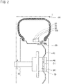
Fig. 2 is a cross-sectional view of the wheel to which the power generator is attached. -
Fig. 3 is a partially broken perspective view of the power generator. -
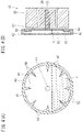
Fig. 4(A) is a front cross-sectional view of a container portion, andFig. 4(B) is a side cross-sectional view of the power generator. -
Fig. 5 is a cross-sectional view of liquid in the container portion when a rotor co-rotates with a stator. -
Fig. 6 is a partially broken perspective view of a power generator according to a second embodiment. -
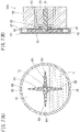
Fig. 7(A) is a front cross-sectional view of a container portion, andFig. 7(B) is a side cross-sectional view of the power generator. -
Fig. 8 is a cross-sectional view of liquid in the container portion when a rotor co-rotates with a stator. -
Fig. 9 is a front cross-sectional view of a container portion of a power generator according to another embodiment. -
Figs. 1 and2 illustrate apower generator 10 of the present embodiment. Thepower generator 10 is assembled on awheel 81 of avehicle 80. Specifically, thepower generator 10 includes a motor including a stator 20 (seeFig. 4(B) ) fixed to thewheel 81 and arotor 30 rotatably supported by thestator 20. Thepower generator 10 can generate electric power by relative rotation between thestator 20 and therotor 30. - The
stator 20 is fixed to, for example, an outer side part of ahub 84, of thewheel 81 fixed to thewheel shaft 83, in a vehicle width direction (seeFig. 2 ), and is disposed so as to surround therotor 30. Therotor 30 has, for example, a columnar shape, is supported by thestator 20 via a bearing (not shown), and is disposed coaxially with the wheel 81 (with the wheel shaft 83). Examples of the motor constituting thepower generator 10 include a stepping motor without being limited thereto, and a motor suitable for various types of power generation can be used. - As shown in
Fig. 4(B) , acenter shaft 31 protrudes coaxially with thewheel 81 from the center of the surface, of therotor 30, directed outward in the vehicle width direction. Acontainer portion 40 is fixed to a tip part of thecenter shaft 31. - The
container portion 40 has a hollow disk shape, and the center of thecontainer portion 40 is fixed to thecenter shaft 31. Thecontainer portion 40 can rotate integrally with the center shaft 31 (that is, with the rotor 30). In detail, thecontainer portion 40 includes: abase wall 41 having a circular plate shape whose center is fixed to thecenter shaft 31; aperipheral wall 42 protruding from an outer edge part of thebase wall 41 to a side away from therotor 30; and atip wall 43 closing theperipheral wall 42 from the opposite side to therotor 30. An enclosed space is formed in a portion surrounded by thebase wall 41, theperipheral wall 42, and thetip wall 43. - As illustrated in
Figs. 3 and4(A) , liquid L is stored in the enclosed space of thecontainer portion 40. Specifically, the liquid L is stored in thecontainer portion 40 in an amount smaller than a volume of thecontainer portion 40, and in the example of the present embodiment, the amount of the liquid L is less than half the volume of thecontainer portion 40 so that a liquid level of the liquid L is lower than a rotation center of thewheel 81 when thecontainer portion 40 is in a stationary state. Examples of the liquid L include antifreeze fluid. - Here, in the
power generator 10, theblade portions 50 fixed to therotor 30 are housed in thecontainer portion 40. Theblade portions 50 are disposed so as to be at least partially immersed in the liquid L. In the present embodiment,blade portions 50 protrude from an inner peripheral surface of theperipheral wall 42 of thecontainer portion 40 toward the center (rotation center) of thecontainer portion 40. In addition, a plurality of (for example, eight) theblade portions 50 is provided, and is arranged at equal intervals in a circumferential direction of thecontainer portion 40, for example. In the present embodiment, someblade portions 50 among theblade portions 50 are entirely immersed in the liquid L when therotor 30 is in a stationary state. In the example of the present embodiment, theblade portions 50 are each formed in an elongated isosceles triangle shape tapered toward the center of thecontainer portion 40 when viewed in the direction toward the central axis of therotor 30. In the present embodiment, theblade portions 50 are integrally formed with thebase wall 41 and theperipheral wall 42 of thecontainer portion 40, but may be formed separately from thecontainer portion 40 and fixed to thecontainer portion 40. - As illustrated in
Fig. 4(B) , in the example of the present embodiment, gaps are formed between thetip walls 43 of thecontainer portions 40 and theblade portions 50. The gaps constitutecommunication flow paths 45 through which the liquid L freely flows between regions on both sides of eachblade portion 50 in the circumferential direction of thecontainer portion 40. - When the
wheel 81 rotates at the time of thevehicle 80 starting to run, thestator 20 rotates integrally with thewheel 81. At this time, inertia works to keep the position of the liquid L in thecontainer portion 40.
Here, theblade portions 50 disposed in thecontainer portion 40 and fixed to therotor 30 are at least partially immersed in the liquid L. Therefore, even if thewheel 81 starts to rotate, the rotation of theblade portion 50, in other words, the rotation of therotor 30 can be easily reduced by resistance between the liquid L and theblade portions 50. As a result, when thewheel 81 rotates, the stator and the rotor can be rotated relatively to each other to generate electric power. As a result, it is possible to effectively use rotational energy of the tire to supply electric power to the electric device. In thepower generator 10 of the present embodiment, since theblade portions 50 that are immersed in the liquid L are provided, it is possible to restrain therotor 30 from corotating with thewheel 81 as compared with a case where theblade portions 50 are not provided. - Further, in the
power generator 10 of the present embodiment, the plurality ofblade portions 50 is provided to protrude from the inner peripheral surface of thecontainer portion 40 fixed to therotor 30, toward the rotation center side. As a result, the resistance between theblade portions 50 and the liquid L can be large, and the rotation of therotor 30 can be reduced so that the relative rotation of therotor 30 with respect to thestator 20 can be increased. - Note that, if the
power generator 10 is configured with, for example, a stepping motor, it is also possible to generate electric power using minute relative rotation of therotor 30 due to swing of the liquid L, and it is possible to continuously generate power using the continuous swing of the liquid L. In addition, as the number of poles and the number of slots of thepower generator 10 are larger, it is possible to generate power even with more minute rotation of therotor 30 caused by shake of the liquid L or the like. - Here, when the
wheel 81 rotates at a high speed, therotor 30 may rotate together due to friction of a bearing or the like. However, in this case, since the liquid L moves to the outer peripheral part of thecontainer portion 40 due to centrifugal force and can therefore be disposed along the entire circumferential direction of the container portion 40 (seeFig. 5 ), it is possible to restrain the balance of thewheel 81 from being lost due to the rotation of therotor 30. Note that, a configuration can be considered in which, instead of the liquid L, a solid weight eccentric from a rotation center of therotor 30 is fixed to therotor 30 so that therotor 30 and thestator 20 are made to rotate relatively to each other. However, in this configuration, when therotor 30 co-rotates with thewheel 81, the balance of thewheel 81 is deteriorated. On the other hand, in thepower generator 10 of the present embodiment, it is possible to prevent such deterioration of the balance by storing the liquid L in thecontainer portion 40 as described above. - In the present embodiment, since the
communication flow paths 45 are provided on the lateral sides of base end parts of theblade portions 50, when thewheel 81 rotates at a high speed and therotor 30 co-rotates, the liquid L easily moves in the circumferential direction of thecontainer portion 40 through thecommunication flow paths 45, and the liquid L is easily disposed along the entire circumferential direction. As a result, it is possible to further prevent or reduce occurrence of an imbalance due to the rotation of therotor 30. Further, in thepower generator 10, since thecontainer portion 40 has a hollow disk shape, when thewheel 81 rotates at a high speed and therotor 30 co-rotates, it is possible to make it more difficult to cause an imbalance due to the rotation of therotor 30. Further, since thecontainer portion 40 has a disk shape, thepower generator 10 can be made compact in the rotation axis direction of therotor 30. - However, if the relative rotation between the
stator 20 and therotor 30 becomes too fast during the high-speed rotation of thewheel 81, there is a possibility that the rotation speed exceeds an allowable rotation speed of the bearing between thestator 20 and therotor 30 and thus to break the bearing. To address this issue, thepower generator 10 includes a co-rotation unit that purposely causes therotor 30 to co-rotate with the stator 20 (the wheel 81) when the rotation speed of the relative rotation between thestator 20 and therotor 30 exceeds a predetermined value. Specifically, the co-rotation unit includes, for example, a load changing unit (for example, a variable resistor) that is connected in series with an electric device in a power generation circuit in which thepower generator 10 is connected to the electric device that receives electric power from thepower generator 10. The co-rotation unit can cause therotor 30 and thestator 20 to co-rotate by changing a load of the load changing unit (for example, by increasing a resistance value of the variable resistance to reduce the current of the power generation circuit). As described above, it is also possible to generate torque for co-rotation between therotor 30 and thestator 20, depending on the load of the power generation circuit. - As illustrated in
Fig. 2 , thepower generator 10 of the present embodiment is provided in, for example, a tirestate monitoring device 100 that monitors a state of thetire 82. The tirestate monitoring device 100 is provided with a tirestate monitoring terminal 90 that is connected to thepower generator 10 and receives electric power from thepower generator 10. The tirestate monitoring terminal 90 is fixed to thewheel 81, includes asensor 91 in thetire 82, and transmits a detection result of thesensor 91 to an external receiver, for example, wirelessly. Examples of thesensor 91 include a sensor that detects an internal pressure of thetire 82, a temperature sensor, and the like. Alternatively, for example, the tirestate monitoring terminal 90 is attached to atire valve 89 or the like attached to thewheel 81. Note that a rechargeable battery may be provided in the power generation circuit of thepower generator 10. -
Fig. 6 illustrates apower generator 10V of a second embodiment. Thepower generator 10V of the present embodiment is similar to thepower generator 10 of the first embodiment in that blade portions are fixed to arotor 30, but is different in that acontainer portion 40 is fixed to astator 20 instead of therotor 30. As in the first embodiment, liquid L is stored in thecontainer portion 40 in an amount smaller than a volume of thecontainer portion 40. - As illustrated in
Fig. 7(B) , in the present embodiment, abase wall 41 of thecontainer portion 40 is fixed to thestator 20. A through-hole 46 is formed at the center of thebase wall 41, and acenter shaft 31 of therotor 30 passes through the through-hole 46. Anannular seal portion 48 is fixed to an inner surface of the through-hole 46 of thebase wall 41. Theseal portion 48 seals between the inner surface of the through-hole 46 of thebase wall 41 and thecenter shaft 31. Thecenter shaft 31 can rotate in a state of being inserted through theseal portion 48. - As illustrated in
Figs. 6 and7(A) ,blade portions 60 protrude in the radial direction of thecontainer portion 40 from a tip part of thecenter shaft 31. In the example of the present embodiment, the plurality ofblade portions 60 is provided to protrude radially from a rotation center of therotor 30. For example, theblade portions 60 are arranged at equal intervals in a circumferential direction of thecontainer portion 40. In the example illustrated inFig. 7(A) , the fourblade portions 60 are provided, and a group of fourblade portions 60 is arranged in a cross shape. - A length of each blade portion 60 (that is, a turning radius) is smaller than a radius of an enclosed space in the container portion 40 (half of an inner diameter of a peripheral wall 42). Therefore,
communication flow paths 49 through which the liquid L can freely pass in the circumferential direction are formed between the tips of theblade portions 60 and theperipheral wall 42 of thecontainer portion 40. Further, gaps through which the liquid L can pass are also formed between thebase wall 41 of thecontainer portion 40 and respective ones of theblade portions 60 and between thetip wall 43 and respective ones of the blade portions 60 (seeFig. 7(B) ). - The
power generator 10V of the present embodiment can also achieve effects similar to those of thepower generator 10 of the first embodiment. Specifically, in thepower generator 10V, when thewheel 81 rotates at the time of thevehicle 80 starting to run, thestator 20 and thecontainer portion 40 rotate integrally. At this time, inertia works to keep the liquid L at the same position in thecontainer portion 40. Here, theblade portions 60 fixed to therotor 30 and disposed in thecontainer portion 40 are at least partially immersed in the liquid L. Therefore, rotation of the blade portions 60 (that is, the rotor 30) can be reduced by resistance between the liquid L and theblade portions 60. As a result, thestator 20 and therotor 30 can be rotated relatively to each other to generate power. - Further, in the
power generator 10V, since the plurality ofblade portions 60 is provided to radially protrude from the rotation center of therotor 30, resistance between theblade portions 60 and the liquid can be made large. As a result, the rotation of therotor 30 can be easily reduced, and thestator 20 and therotor 30 can be easily rotated relatively each other. In addition, since the radius of the space in thecontainer portion 40 is larger than the turning radius of theblade portions 60, gaps are formed between the inner peripheral surface of thecontainer portion 40 and theblade portions 60. Therefore, when the wheel rotates at a high speed and the rotor co-rotates, the liquid L easily moves in the circumferential direction of thecontainer portion 40 through the gaps, and the liquid L is easily disposed along the entire circumferential direction (seeFig. 8 ). As a result, it is possible to further prevent or reduce an imbalance of thewheel 81 due to the rotation of the rotor. - The
power generator 10V of the present embodiment may also be provided in the tirestate monitoring device 100 in the same manner as in the first embodiment. -
- (1) In the above embodiment, the device that receives electric power from the
power generator 10 is the tirestate monitoring device 100 without being limited thereto, and a light emitting device or the like attached to thewheel 81 may receive the electric power, for example. - (2) In the above embodiments, the gaps through which the liquid L can pass are formed between the blade portions 50 (60) and the
tip wall 43 of thecontainer portion 40, but theblade portions 50 and thetip wall 43 may be integrally formed with no gap therebetween. - (3) In the first embodiment, the
blade portions 50 may be replaced byblade portions 50W illustrated inFig. 9 . In apower generator 10W illustrated in the drawing, theblade portions 50W are integrally formed with abase wall 41 or atip wall 43 of acontainer portion 40. In addition, gaps through which liquid L can pass are formed between theblade portions 50W and aperipheral wall 42 of thecontainer portion 40. In this case, theblade portions 50 may be separated from each other at a central part of thecontainer portion 40 or may be connected to each other. In addition, theblade portions 50 may be integrally formed with both thebase wall 41 and thetip wall 43, or when theblade portions 50 are integrally formed with one of thebase wall 41 and thetip wall 43, theblade portions 50 may be apart from the other. In addition, in a manner similar to the first embodiment,blade portions 50 protruding from theperipheral wall 42 may be provided at positions, between theblade portions 50W, in the circumferential direction in thecontainer portion 40 of thepower generator 10W illustrated inFig. 9 . -
- 10
- power generator
- 20
- stator
- 30
- rotor
- 40
- container portion
- 50
- blade portion
- 60
- blade portion
- 100
- tire state monitoring device
- L
- liquid
Claims (7)
- A power generator comprising:a stator fixed to a wheel;a rotor disposed coaxially with the wheel and rotatably supported by the stator, the power generator generating electric power by relative rotation between the stator and the rotor, and supplying the electric power to an electric device attached to the wheel,a blade portion fixed to the rotor;a container portion that is fixed to one of the rotor and the stator and houses the blade portion; anda liquid which is contained in the container portion in an amount smaller than a volume of the container portion and in which at least a part of the blade portion is immersed.
- The power generator according to claim 1, wherein the container portion is fixed to the stator, and
the power generator includes:a penetration portion that is provided on the rotor and penetrates the container portion; anda seal portion that seals between the penetration portion and an inner surface of a through-hole of the container portion through which the penetration portion passes. - The power generator according to claim 2, wherein a plurality of the blade portions is provided to radially protrude from a rotation center of the rotor, and
the container portion has a cylindrical structure having a space having a radius larger than a turning radius of the plurality of blade portions. - The power generator according to claim 1, wherein the container portion is fixed to the rotor, and
the blade portion is formed integrally with or is fixed to an inner surface of the container portion. - The power generator according to claim 4, wherein a plurality of the blade portions is provided to protrude from an inner peripheral surface of the container portion toward a rotation center side, and
a communication flow path through which the liquid freely flows, in a circumferential direction of the container portion, between regions on both sides of each of the blade portions is provided on a lateral side of the each of the blade portions. - The power generator according to claim 5, wherein the container portion has a hollow disk shape.
- A tire state monitoring device comprising:the power generator according to any one of claims 1 to 6; anda tire state monitoring terminal that is fixed to the wheel, includes a sensor disposed inside a tire, and receives electric power from the power generator.
Applications Claiming Priority (2)
| Application Number | Priority Date | Filing Date | Title |
|---|---|---|---|
| JP2020149485A JP2022043947A (en) | 2020-09-04 | 2020-09-04 | Generator and tire condition monitoring device |
| PCT/JP2021/016847 WO2022049827A1 (en) | 2020-09-04 | 2021-04-27 | Generator and tire condition monitoring device |
Publications (2)
| Publication Number | Publication Date |
|---|---|
| EP4027497A1 true EP4027497A1 (en) | 2022-07-13 |
| EP4027497A4 EP4027497A4 (en) | 2022-11-16 |
Family
ID=80490976
Family Applications (1)
| Application Number | Title | Priority Date | Filing Date |
|---|---|---|---|
| EP21863886.4A Withdrawn EP4027497A4 (en) | 2020-09-04 | 2021-04-27 | Generator and tire condition monitoring device |
Country Status (5)
| Country | Link |
|---|---|
| US (1) | US20240060857A1 (en) |
| EP (1) | EP4027497A4 (en) |
| JP (1) | JP2022043947A (en) |
| CN (1) | CN114503406A (en) |
| WO (1) | WO2022049827A1 (en) |
Families Citing this family (1)
| Publication number | Priority date | Publication date | Assignee | Title |
|---|---|---|---|---|
| DE102022106429A1 (en) * | 2022-03-18 | 2023-09-21 | Ronal Ag | Method for operating an electromagnetic power generator for a wheel and power generator for a wheel |
Family Cites Families (13)
| Publication number | Priority date | Publication date | Assignee | Title |
|---|---|---|---|---|
| US2403478A (en) * | 1941-06-25 | 1946-07-09 | Burnat Henri Louis | Damping flywheel |
| US4075603A (en) * | 1976-10-04 | 1978-02-21 | Gould Inc. | Apparatus and method for indicating condition of a rotating body |
| JPS5914634B2 (en) * | 1981-05-06 | 1984-04-05 | 株式会社前川製作所 | Force storage device using variable inertia body |
| US6910372B2 (en) * | 2003-03-21 | 2005-06-28 | Bridgestone/Firestone North American Tire, Llc | Non-attached electronic monitoring device for tire |
| TW201024117A (en) * | 2008-12-18 | 2010-07-01 | Jiann-Huey Huang | Tire monitoring system without battery |
| US8707821B2 (en) * | 2009-08-26 | 2014-04-29 | Patrick J Dugas | Containment reinforced flywheel |
| KR100977355B1 (en) * | 2009-10-06 | 2010-08-20 | 송명준 | Tire pressure controlling device including tire pressure monitoring system |
| JP5508124B2 (en) * | 2010-05-07 | 2014-05-28 | 株式会社ブリヂストン | In-tire power generator |
| CN202309476U (en) * | 2011-07-22 | 2012-07-04 | 柳峰 | Energy-saving separating-type combined generator and device |
| CN104025430B (en) * | 2011-12-27 | 2016-08-24 | 奥田胜司 | Axle-driven generator |
| US20140007737A1 (en) * | 2012-07-09 | 2014-01-09 | Shih-Hang Chou | Power auxiliary device |
| JP2018105229A (en) * | 2016-12-27 | 2018-07-05 | 三菱重工サーマルシステムズ株式会社 | Variable inertia and rotary compressor |
| WO2019193744A1 (en) * | 2018-04-06 | 2019-10-10 | 太平洋工業株式会社 | Tire valve |
-
2020
- 2020-09-04 JP JP2020149485A patent/JP2022043947A/en not_active Ceased
-
2021
- 2021-04-27 CN CN202180005689.5A patent/CN114503406A/en active Pending
- 2021-04-27 US US17/766,641 patent/US20240060857A1/en not_active Abandoned
- 2021-04-27 EP EP21863886.4A patent/EP4027497A4/en not_active Withdrawn
- 2021-04-27 WO PCT/JP2021/016847 patent/WO2022049827A1/en not_active Ceased
Also Published As
| Publication number | Publication date |
|---|---|
| WO2022049827A1 (en) | 2022-03-10 |
| CN114503406A (en) | 2022-05-13 |
| EP4027497A4 (en) | 2022-11-16 |
| US20240060857A1 (en) | 2024-02-22 |
| JP2022043947A (en) | 2022-03-16 |
Similar Documents
| Publication | Publication Date | Title |
|---|---|---|
| JP6927224B2 (en) | Drive device | |
| CN102164680B (en) | Whizzer | |
| US9206788B2 (en) | Electrical generator | |
| US7503747B2 (en) | Rotatable duct type shrouded rotating wing | |
| US9937570B2 (en) | Cutting machine, especially a circular saw | |
| JP2013055728A (en) | Rotary electric machine | |
| WO2013136405A1 (en) | Rotating electrical machine | |
| US20240060857A1 (en) | Power generator and tire state monitoring device | |
| JP2014230393A (en) | Rotary electric machine | |
| WO2016130497A1 (en) | Bearings for a turbocharger | |
| KR20160089784A (en) | Housing and Motor having the same | |
| WO2018030374A1 (en) | Drive device | |
| JP2013207930A (en) | Stator structure of rotary electric machine | |
| JP2000341909A (en) | Single-bearing permanent magnet motor and single-bearing fan motor | |
| EP2618465B1 (en) | Electrical machine including two rotors and at least two bearings, with a single bearing arranged between the two rotors along the axis of rotation | |
| JP3981143B1 (en) | Power generator | |
| JP2019170030A (en) | Motor cooling system | |
| JP5730740B2 (en) | Rotating electric machine | |
| EP2544337A1 (en) | Drive motor for an electric vehicle | |
| JP4435848B1 (en) | Shaft fixed type fluid dynamic pressure bearing device, spindle motor and recording disk device having the same | |
| JP6651496B2 (en) | Rotating electric machine | |
| JP2009281228A (en) | Wind turbine generator | |
| CN101594012B (en) | Motor and rotor thereof | |
| CN203783918U (en) | Multi-rotor pipeline pump | |
| CN110872735A (en) | Balance ring for compensating unbalance of spinning machine rotor |
Legal Events
| Date | Code | Title | Description |
|---|---|---|---|
| STAA | Information on the status of an ep patent application or granted ep patent |
Free format text: STATUS: THE INTERNATIONAL PUBLICATION HAS BEEN MADE |
|
| PUAI | Public reference made under article 153(3) epc to a published international application that has entered the european phase |
Free format text: ORIGINAL CODE: 0009012 |
|
| STAA | Information on the status of an ep patent application or granted ep patent |
Free format text: STATUS: REQUEST FOR EXAMINATION WAS MADE |
|
| 17P | Request for examination filed |
Effective date: 20220404 |
|
| AK | Designated contracting states |
Kind code of ref document: A1 Designated state(s): AL AT BE BG CH CY CZ DE DK EE ES FI FR GB GR HR HU IE IS IT LI LT LU LV MC MK MT NL NO PL PT RO RS SE SI SK SM TR |
|
| REG | Reference to a national code |
Ref country code: DE Ref legal event code: R079 Free format text: PREVIOUS MAIN CLASS: H02K0007000000 Ipc: H02K0007180000 |
|
| STAA | Information on the status of an ep patent application or granted ep patent |
Free format text: STATUS: EXAMINATION IS IN PROGRESS |
|
| A4 | Supplementary search report drawn up and despatched |
Effective date: 20221017 |
|
| RIC1 | Information provided on ipc code assigned before grant |
Ipc: F16F 9/12 20060101ALN20221011BHEP Ipc: F16F 15/31 20060101ALN20221011BHEP Ipc: B60C 23/04 20060101ALI20221011BHEP Ipc: H02K 7/02 20060101ALI20221011BHEP Ipc: H02K 7/18 20060101AFI20221011BHEP |
|
| 17Q | First examination report despatched |
Effective date: 20221111 |
|
| DAV | Request for validation of the european patent (deleted) | ||
| DAX | Request for extension of the european patent (deleted) | ||
| STAA | Information on the status of an ep patent application or granted ep patent |
Free format text: STATUS: THE APPLICATION IS DEEMED TO BE WITHDRAWN |
|
| 18D | Application deemed to be withdrawn |
Effective date: 20241101 |