EP4027438A1 - Pouch packaged lithium-ion battery with tooth-shaped sealing edge - Google Patents
Pouch packaged lithium-ion battery with tooth-shaped sealing edge Download PDFInfo
- Publication number
- EP4027438A1 EP4027438A1 EP21194842.7A EP21194842A EP4027438A1 EP 4027438 A1 EP4027438 A1 EP 4027438A1 EP 21194842 A EP21194842 A EP 21194842A EP 4027438 A1 EP4027438 A1 EP 4027438A1
- Authority
- EP
- European Patent Office
- Prior art keywords
- tab
- cathode
- sealing edge
- anode
- tooth
- Prior art date
- Legal status (The legal status is an assumption and is not a legal conclusion. Google has not performed a legal analysis and makes no representation as to the accuracy of the status listed.)
- Pending
Links
- 238000007789 sealing Methods 0.000 title claims abstract description 85
- 229910001416 lithium ion Inorganic materials 0.000 title claims abstract description 33
- HBBGRARXTFLTSG-UHFFFAOYSA-N Lithium ion Chemical compound [Li+] HBBGRARXTFLTSG-UHFFFAOYSA-N 0.000 title claims abstract description 31
- 235000015110 jellies Nutrition 0.000 claims abstract description 43
- 239000008274 jelly Substances 0.000 claims abstract description 43
- 239000002985 plastic film Substances 0.000 claims abstract description 22
- 229920006255 plastic film Polymers 0.000 claims abstract description 22
- 239000000565 sealant Substances 0.000 claims abstract description 16
- 238000003466 welding Methods 0.000 claims description 8
- 238000005452 bending Methods 0.000 description 7
- 239000003792 electrolyte Substances 0.000 description 7
- 238000004804 winding Methods 0.000 description 5
- 230000005611 electricity Effects 0.000 description 4
- 238000007731 hot pressing Methods 0.000 description 4
- 238000007599 discharging Methods 0.000 description 3
- 238000000034 method Methods 0.000 description 3
- XAGFODPZIPBFFR-UHFFFAOYSA-N aluminium Chemical compound [Al] XAGFODPZIPBFFR-UHFFFAOYSA-N 0.000 description 2
- 229910052782 aluminium Inorganic materials 0.000 description 2
- WHXSMMKQMYFTQS-UHFFFAOYSA-N Lithium Chemical compound [Li] WHXSMMKQMYFTQS-UHFFFAOYSA-N 0.000 description 1
- 230000009286 beneficial effect Effects 0.000 description 1
- 238000009826 distribution Methods 0.000 description 1
- 238000005516 engineering process Methods 0.000 description 1
- 238000002513 implantation Methods 0.000 description 1
- 238000009434 installation Methods 0.000 description 1
- 229910052744 lithium Inorganic materials 0.000 description 1
- 238000004519 manufacturing process Methods 0.000 description 1
- 238000012986 modification Methods 0.000 description 1
- 230000004048 modification Effects 0.000 description 1
Images

Classifications
-
- H—ELECTRICITY
- H01—ELECTRIC ELEMENTS
- H01M—PROCESSES OR MEANS, e.g. BATTERIES, FOR THE DIRECT CONVERSION OF CHEMICAL ENERGY INTO ELECTRICAL ENERGY
- H01M50/00—Constructional details or processes of manufacture of the non-active parts of electrochemical cells other than fuel cells, e.g. hybrid cells
- H01M50/10—Primary casings; Jackets or wrappings
- H01M50/102—Primary casings; Jackets or wrappings characterised by their shape or physical structure
- H01M50/105—Pouches or flexible bags
-
- H—ELECTRICITY
- H01—ELECTRIC ELEMENTS
- H01M—PROCESSES OR MEANS, e.g. BATTERIES, FOR THE DIRECT CONVERSION OF CHEMICAL ENERGY INTO ELECTRICAL ENERGY
- H01M50/00—Constructional details or processes of manufacture of the non-active parts of electrochemical cells other than fuel cells, e.g. hybrid cells
- H01M50/10—Primary casings; Jackets or wrappings
- H01M50/172—Arrangements of electric connectors penetrating the casing
- H01M50/174—Arrangements of electric connectors penetrating the casing adapted for the shape of the cells
- H01M50/178—Arrangements of electric connectors penetrating the casing adapted for the shape of the cells for pouch or flexible bag cells
-
- H—ELECTRICITY
- H01—ELECTRIC ELEMENTS
- H01M—PROCESSES OR MEANS, e.g. BATTERIES, FOR THE DIRECT CONVERSION OF CHEMICAL ENERGY INTO ELECTRICAL ENERGY
- H01M10/00—Secondary cells; Manufacture thereof
- H01M10/05—Accumulators with non-aqueous electrolyte
- H01M10/052—Li-accumulators
- H01M10/0525—Rocking-chair batteries, i.e. batteries with lithium insertion or intercalation in both electrodes; Lithium-ion batteries
-
- H—ELECTRICITY
- H01—ELECTRIC ELEMENTS
- H01M—PROCESSES OR MEANS, e.g. BATTERIES, FOR THE DIRECT CONVERSION OF CHEMICAL ENERGY INTO ELECTRICAL ENERGY
- H01M10/00—Secondary cells; Manufacture thereof
- H01M10/05—Accumulators with non-aqueous electrolyte
- H01M10/058—Construction or manufacture
- H01M10/0587—Construction or manufacture of accumulators having only wound construction elements, i.e. wound positive electrodes, wound negative electrodes and wound separators
-
- H—ELECTRICITY
- H01—ELECTRIC ELEMENTS
- H01M—PROCESSES OR MEANS, e.g. BATTERIES, FOR THE DIRECT CONVERSION OF CHEMICAL ENERGY INTO ELECTRICAL ENERGY
- H01M50/00—Constructional details or processes of manufacture of the non-active parts of electrochemical cells other than fuel cells, e.g. hybrid cells
- H01M50/10—Primary casings; Jackets or wrappings
- H01M50/102—Primary casings; Jackets or wrappings characterised by their shape or physical structure
- H01M50/107—Primary casings; Jackets or wrappings characterised by their shape or physical structure having curved cross-section, e.g. round or elliptic
-
- H—ELECTRICITY
- H01—ELECTRIC ELEMENTS
- H01M—PROCESSES OR MEANS, e.g. BATTERIES, FOR THE DIRECT CONVERSION OF CHEMICAL ENERGY INTO ELECTRICAL ENERGY
- H01M50/00—Constructional details or processes of manufacture of the non-active parts of electrochemical cells other than fuel cells, e.g. hybrid cells
- H01M50/10—Primary casings; Jackets or wrappings
- H01M50/116—Primary casings; Jackets or wrappings characterised by the material
- H01M50/124—Primary casings; Jackets or wrappings characterised by the material having a layered structure
-
- H—ELECTRICITY
- H01—ELECTRIC ELEMENTS
- H01M—PROCESSES OR MEANS, e.g. BATTERIES, FOR THE DIRECT CONVERSION OF CHEMICAL ENERGY INTO ELECTRICAL ENERGY
- H01M50/00—Constructional details or processes of manufacture of the non-active parts of electrochemical cells other than fuel cells, e.g. hybrid cells
- H01M50/10—Primary casings; Jackets or wrappings
- H01M50/116—Primary casings; Jackets or wrappings characterised by the material
- H01M50/124—Primary casings; Jackets or wrappings characterised by the material having a layered structure
- H01M50/126—Primary casings; Jackets or wrappings characterised by the material having a layered structure comprising three or more layers
- H01M50/129—Primary casings; Jackets or wrappings characterised by the material having a layered structure comprising three or more layers with two or more layers of only organic material
-
- H—ELECTRICITY
- H01—ELECTRIC ELEMENTS
- H01M—PROCESSES OR MEANS, e.g. BATTERIES, FOR THE DIRECT CONVERSION OF CHEMICAL ENERGY INTO ELECTRICAL ENERGY
- H01M50/00—Constructional details or processes of manufacture of the non-active parts of electrochemical cells other than fuel cells, e.g. hybrid cells
- H01M50/10—Primary casings; Jackets or wrappings
- H01M50/147—Lids or covers
- H01M50/148—Lids or covers characterised by their shape
- H01M50/152—Lids or covers characterised by their shape for cells having curved cross-section, e.g. round or elliptic
-
- H—ELECTRICITY
- H01—ELECTRIC ELEMENTS
- H01M—PROCESSES OR MEANS, e.g. BATTERIES, FOR THE DIRECT CONVERSION OF CHEMICAL ENERGY INTO ELECTRICAL ENERGY
- H01M50/00—Constructional details or processes of manufacture of the non-active parts of electrochemical cells other than fuel cells, e.g. hybrid cells
- H01M50/10—Primary casings; Jackets or wrappings
- H01M50/147—Lids or covers
- H01M50/166—Lids or covers characterised by the methods of assembling casings with lids
- H01M50/169—Lids or covers characterised by the methods of assembling casings with lids by welding, brazing or soldering
-
- H—ELECTRICITY
- H01—ELECTRIC ELEMENTS
- H01M—PROCESSES OR MEANS, e.g. BATTERIES, FOR THE DIRECT CONVERSION OF CHEMICAL ENERGY INTO ELECTRICAL ENERGY
- H01M50/00—Constructional details or processes of manufacture of the non-active parts of electrochemical cells other than fuel cells, e.g. hybrid cells
- H01M50/10—Primary casings; Jackets or wrappings
- H01M50/172—Arrangements of electric connectors penetrating the casing
- H01M50/174—Arrangements of electric connectors penetrating the casing adapted for the shape of the cells
- H01M50/179—Arrangements of electric connectors penetrating the casing adapted for the shape of the cells for cells having curved cross-section, e.g. round or elliptic
-
- H—ELECTRICITY
- H01—ELECTRIC ELEMENTS
- H01M—PROCESSES OR MEANS, e.g. BATTERIES, FOR THE DIRECT CONVERSION OF CHEMICAL ENERGY INTO ELECTRICAL ENERGY
- H01M50/00—Constructional details or processes of manufacture of the non-active parts of electrochemical cells other than fuel cells, e.g. hybrid cells
- H01M50/10—Primary casings; Jackets or wrappings
- H01M50/172—Arrangements of electric connectors penetrating the casing
- H01M50/174—Arrangements of electric connectors penetrating the casing adapted for the shape of the cells
- H01M50/181—Arrangements of electric connectors penetrating the casing adapted for the shape of the cells for button or coin cells
-
- H—ELECTRICITY
- H01—ELECTRIC ELEMENTS
- H01M—PROCESSES OR MEANS, e.g. BATTERIES, FOR THE DIRECT CONVERSION OF CHEMICAL ENERGY INTO ELECTRICAL ENERGY
- H01M50/00—Constructional details or processes of manufacture of the non-active parts of electrochemical cells other than fuel cells, e.g. hybrid cells
- H01M50/10—Primary casings; Jackets or wrappings
- H01M50/183—Sealing members
- H01M50/184—Sealing members characterised by their shape or structure
-
- H—ELECTRICITY
- H01—ELECTRIC ELEMENTS
- H01M—PROCESSES OR MEANS, e.g. BATTERIES, FOR THE DIRECT CONVERSION OF CHEMICAL ENERGY INTO ELECTRICAL ENERGY
- H01M50/00—Constructional details or processes of manufacture of the non-active parts of electrochemical cells other than fuel cells, e.g. hybrid cells
- H01M50/10—Primary casings; Jackets or wrappings
- H01M50/183—Sealing members
- H01M50/186—Sealing members characterised by the disposition of the sealing members
-
- H—ELECTRICITY
- H01—ELECTRIC ELEMENTS
- H01M—PROCESSES OR MEANS, e.g. BATTERIES, FOR THE DIRECT CONVERSION OF CHEMICAL ENERGY INTO ELECTRICAL ENERGY
- H01M50/00—Constructional details or processes of manufacture of the non-active parts of electrochemical cells other than fuel cells, e.g. hybrid cells
- H01M50/50—Current conducting connections for cells or batteries
- H01M50/531—Electrode connections inside a battery casing
- H01M50/533—Electrode connections inside a battery casing characterised by the shape of the leads or tabs
-
- H—ELECTRICITY
- H01—ELECTRIC ELEMENTS
- H01M—PROCESSES OR MEANS, e.g. BATTERIES, FOR THE DIRECT CONVERSION OF CHEMICAL ENERGY INTO ELECTRICAL ENERGY
- H01M50/00—Constructional details or processes of manufacture of the non-active parts of electrochemical cells other than fuel cells, e.g. hybrid cells
- H01M50/50—Current conducting connections for cells or batteries
- H01M50/531—Electrode connections inside a battery casing
- H01M50/536—Electrode connections inside a battery casing characterised by the method of fixing the leads to the electrodes, e.g. by welding
-
- H—ELECTRICITY
- H01—ELECTRIC ELEMENTS
- H01M—PROCESSES OR MEANS, e.g. BATTERIES, FOR THE DIRECT CONVERSION OF CHEMICAL ENERGY INTO ELECTRICAL ENERGY
- H01M50/00—Constructional details or processes of manufacture of the non-active parts of electrochemical cells other than fuel cells, e.g. hybrid cells
- H01M50/50—Current conducting connections for cells or batteries
- H01M50/543—Terminals
- H01M50/547—Terminals characterised by the disposition of the terminals on the cells
- H01M50/548—Terminals characterised by the disposition of the terminals on the cells on opposite sides of the cell
-
- Y—GENERAL TAGGING OF NEW TECHNOLOGICAL DEVELOPMENTS; GENERAL TAGGING OF CROSS-SECTIONAL TECHNOLOGIES SPANNING OVER SEVERAL SECTIONS OF THE IPC; TECHNICAL SUBJECTS COVERED BY FORMER USPC CROSS-REFERENCE ART COLLECTIONS [XRACs] AND DIGESTS
- Y02—TECHNOLOGIES OR APPLICATIONS FOR MITIGATION OR ADAPTATION AGAINST CLIMATE CHANGE
- Y02E—REDUCTION OF GREENHOUSE GAS [GHG] EMISSIONS, RELATED TO ENERGY GENERATION, TRANSMISSION OR DISTRIBUTION
- Y02E60/00—Enabling technologies; Technologies with a potential or indirect contribution to GHG emissions mitigation
- Y02E60/10—Energy storage using batteries
-
- Y—GENERAL TAGGING OF NEW TECHNOLOGICAL DEVELOPMENTS; GENERAL TAGGING OF CROSS-SECTIONAL TECHNOLOGIES SPANNING OVER SEVERAL SECTIONS OF THE IPC; TECHNICAL SUBJECTS COVERED BY FORMER USPC CROSS-REFERENCE ART COLLECTIONS [XRACs] AND DIGESTS
- Y02—TECHNOLOGIES OR APPLICATIONS FOR MITIGATION OR ADAPTATION AGAINST CLIMATE CHANGE
- Y02P—CLIMATE CHANGE MITIGATION TECHNOLOGIES IN THE PRODUCTION OR PROCESSING OF GOODS
- Y02P70/00—Climate change mitigation technologies in the production process for final industrial or consumer products
- Y02P70/50—Manufacturing or production processes characterised by the final manufactured product
Definitions
- the present disclosure relates to the field of battery technologies, and in particular to a pouch packaged lithium-ion battery with a tooth-shaped sealing edge.
- a lithium-ion battery is a secondary battery (rechargeable battery) that works based on the movement of lithium ions between a cathode and an anode.
- Li + is embedded and de-embedded back and forth between the two electrodes.
- Li + is de-embedded from the cathode and embedded into the anode through electrolyte so that the cathode is in a lithium-rich state.
- the existing lithium-ion battery includes a cathode, an anode, a film and electrolyte. The cathode and the anode are infiltrated in the electrolyte.
- the lithium ions move between the cathode and the anode with the electrolyte as a medium to realize the charging and discharging of the battery.
- the cathode and the anode are required to be separated by the film.
- a cell of the existing lithium-ion battery has a structure with a large volume, resulting in a lower energy density in a unit volume, inconvenience of installation and use, and a crease of the sealing edge after bending.
- a pouch packaged lithium-ion battery with a tooth-shaped sealing edge is provided.
- the present disclosure provides a pouch packaged lithium-ion battery with a tooth-shaped sealing edge, including a main body; the main body includes an aluminum-plastic film; wherein the aluminum-plastic film defines a cavity where a jelly roll is arranged therein; the jelly roll includes a cathode, an anode and a film separating the cathode and the anode; the cathode, the film and the anode are winded and overlaid to form a shape of cylinder substantially; a cathode tab is arranged on a side of the jelly roll, and an anode tab is arranged on the other side of the jelly roll; the cathode tab is connected to the cathode electrically, and the anode tab is connected to the anode electrically; a part of the aluminum-plastic film in contact with the cathode tab and the anode tab is bent and extends toward an outside of the lithium-ion battery to form a sealing edge in the middle of the main body; the cathode tab and the
- an end of the cathode tab close to the jelly roll is arranged with a first clamping part in an inverted U type.
- the first clamping part is fixed to the cathode by welding.
- an end of the anode tab close to the jelly roll is arranged with a second clamping part in an inverted U type.
- the second clamping part is fixed to the anode by welding.
- the film includes two layers, one layer is arranged on an outer side of the cathode and the other layer is arranged on an outer side of the anode.
- a joint between the sealing edge and the main body is coated with a sealant.
- the cathode tab and the anode tab are symmetrically distributed on both sides of the jelly roll.
- a radial angle between the cathode tab and the main body is 45° - 90° and a radial angle between the anode tab and the main body is also 45° - 90°.
- the cathode, the film and the anode are winded and overlaid to form a shape of cylinder substantially. That is, the jelly roll is formed by winding and overlaying in an order: the cathode, the film, the anode, and the film, therefore the film between the cathode and the anode can at least limit the occurrence of a short.
- the integral structure of the jelly roll is compact after wending, thereby improving the energy density of the battery.
- the cathode tab and the anode tab extend horizontally and penetrate the sealing edge. A joint between the cathode and the sealing edge is covered with a tab sealant, and a joint between the anode tab and the sealing edge is also covered with the tab sealant.
- the sealing edge, the cathode tab and the anode tab are bent upward to attach to a surface of the main body, the width of the sealing edge in a diameter direction may be thus reduced.
- the cathode tab and the anode tab are convenient to be connected to a circuit after extending upward, so that the whole battery may be thus conveniently assembled to an inside of products of customers.
- the surface of the sealing edge is arranged with grooves, and the grooves are tooth-shaped in appearance and distributed in an annular array, therefore a crease is incapable to be generate and the sealing edge after bent is regular and beautiful.
- the embodiment provides a pouch packaged lithium-ion battery with a tooth-shaped sealing edge, including a main body 7.
- the main body 7 includes an aluminum-plastic film 8 with good insulativity.
- the aluminum-plastic film 8 defines a cavity where a jelly roll 4 is arranged therein.
- the jelly roll 4 includes a cathode 1, an anode 2 and a film 3 separating the cathode 1 and the anode 2.
- the cathode 1, the film 3 and the anode 2 are winded and overlaid to form a shape of cylinder substantially. That is, the jelly roll 4 is formed by winding and overlaying in an order: the cathode 1, the film 3, the anode 2, and the film 3.
- a cathode tab 5 and an anode tab 6 are respectively arranged on both sides of the jelly roll 4.
- the cathode tab 5 is connected to the cathode 1 electrically
- the anode tab 6 is connected to the anode 2 electrically.
- a joint between the cathode tab 5 and the cathode 1 and a joint between the anode tab 6 and the anode 2 may be fixed by welding so that both the cathode 1 and the anode 2 can conduct electricity.
- a part of the aluminum-plastic film 8 in contact with the cathode tab 5 and the anode tab 6 is bent and extends toward an outside of the lithium-ion battery to form a sealing edge 10 in the middle of the main body 7 (that is, a first bending happens).
- the sealing edge 10 and aluminum-plastic film 8 are sealed and molded by hot-pressing.
- the cathode tab 5 and the anode tab 6 extend horizontally and penetrate the sealing edge 10. That is, after the cathode tab 5 and the anode tab 6 penetrate the sealing edge 10, the sealing edge 10 may be divided into 2 layers in a thickness direction, and the cathode tab 5 and the anode tab 6 are sandwiched between the 2 layers.
- a joint between the cathode 5 and the sealing edge 10 is covered with a tab sealant 9.
- a joint between the anode tab 6 and the sealing edge 10 is also covered with the tab sealant 9.
- the sealing edge 10, the cathode tab 5 and the anode tab 6 may be bent upward to attach to a surface of the main body 7 (that is, a second bending happens).
- the cathode 1 and anode 2 are assembled in the sealing aluminum-plastic film 8 formed by stamping, that is, the jelly roll 4 is assembled in the sealing aluminum-plastic film 8 formed by stamping, and an upper portion and a lower portion of the aluminum plastic film 8 are sealed together by hot pressing.
- the jelly roll 4 is injected with electrolyte, activated and sealed again, the sealing edge 10 on an outside of the jelly roll 4 is bent axially, so that the sealing edge 10 may attach to the main body 7 tightly.
- the width of the sealing edge 10 in a diameter direction may be reduced, that is, the diameter of the battery may be reduced by 3-5mm.
- the energy density of the battery may be improved.
- the cathode tab 5 and the anode tab 6 of the battery extend out the main body 7 at a radial angle of 45° - 90° to protect the assembly and connection of a printed circuit board (PCB). Since the sealing edge 10 is bent to the main body, the whole battery may be thus assembled to an inside of products of customers, which is convenient and efficient.
- the surface of the sealing edge 10 may be arranged with grooves 13.
- the grooves 13 may be tooth-shaped in appearance and distributed in an annular array, so that the sealing edge 10 after bent and attached to the main body 7 is symmetrical, tidy and regular, and occurrences of random distribution of teeth and fold rebounding automatically formed after bending without insection may be limited.
- An end of the cathode tab 5 close to the jelly roll 4 may be arranged with a first clamping part 11 in an inverted U type (that is, the first clamping part 11 defines an opening to match an edge of the jelly roll 4).
- the first clamping part 11 and the cathode tab 5 are formed integrally by stamping.
- the first clamping part 11 is fixed to the cathode 1 by welding, so that the joint is strong and can conduct electricity.
- An end of the anode tab 6 close to the jelly roll 4 may be arranged with a second clamping part 12 in an inverted U type (that is, the first clamping part 11 defines an opening to match an edge of the jelly roll 4).
- the second clamping part 12 and the anode tab 6 are formed integrally by stamping.
- the second clamping part 12 is fixed to the anode 2 by welding, so that the joint is strong and can conduct electricity.
- the film 3 includes two layers. One layer is arranged on an outside of the cathode 1 and the other layer is arranged on an outside of the anode 2, which can at least limit the short circuit since the cathode 1 cannot contact with the anode 2 directly after winding.
- a joint between the sealing edge 10 and the main body 7 may be coated with a sealant 14, so that the sealing edge 10 cannot rebound after bending, ensuring a firm structure thereof.
- cathode tab 5 and the anode tab 6 may be symmetrically distributed on both sides of the jelly roll 4.
- the pouch packaged lithium-ion battery with a tooth-shaped sealing edge in the embodiment 2 as shown in FIGS. 4-5 includes: a pouch packaged lithium-ion battery with a jelly roll, including a main body 7.
- the main body 7 includes an aluminum-plastic film 8 with good insulativity.
- the aluminum-plastic film 8 defines a cavity where a jelly roll 4 is arranged therein.
- the jelly roll 4 includes a cathode 1, an anode 2 and a film 3 separating the cathode 1 and the anode 2.
- the cathode 1, the film 3 and the anode 2 are winded and overlaid to form a shape of cylinder substantially. That is, the jelly roll 4 is formed by winding and overlaying in an order: the cathode 1, the film 3, the anode 2, and the film 3.
- a cathode tab 5 and an anode tab 6 are respectively arranged on both sides of the jelly roll 4.
- the cathode tab 5 is connected to the cathode 1 electrically
- the anode tab 6 is connected to the anode 2 electrically.
- a joint between the cathode tab 5 and the cathode 1 and a joint between the anode tab 6 and the anode 2 may be fixed by welding so that both the cathode 1 and the anode 2 can conduct electricity.
- a part of the aluminum-plastic film 8 in contact with the cathode tab 5 and the anode tab 6 is bent and extends toward an outside of the lithium-ion battery to form a sealing edge 10 in the middle of the main body 7 (that is, a first bending happens).
- the sealing edge 10 and aluminum-plastic film 8 are sealed and molded by hot-pressing.
- the cathode tab 5 and the anode tab 6 extend horizontally and penetrate the sealing edge 10.
- a joint between the cathode 5 and the sealing edge 10 is covered with a tab sealant 9.
- a joint between the anode tab 6 and the sealing edge 10 is also covered with the tab sealant 9.
- the sealing edge 10, the cathode tab 5 and the anode tab 6 may be bent upward to attach to a surface of the main body 7 (that is, a second bending happens).
- the cathode 1 and anode 2 are assembled in the sealing aluminum-plastic film 8 formed by stamping, that is, the jelly roll 4 is assembled in the sealing aluminum-plastic film 8 formed by stamping, and an upper portion and a lower portion of the aluminum plastic film 8 are sealed together by hot pressing.
- the sealing edge 10 on an outside of the jelly roll 4 is bent axially, so that the sealing edge 10 may attach to the main body 7 tightly.
- the width of the sealing edge 10 in a diameter direction may be reduced, that is, the diameter of the battery may be reduced by 3-5mm.
- the energy density of the battery may be improved.
- the cathode tab 5 and the anode tab 6 of the battery extend out the main body 7 at a radial angle of 45° - 90° to protect the assembly and connection of the PCB. Since the sealing edge 10 is bent to the main body, the whole battery may be thus assembled to an inside of products of customers, which is convenient and efficient.
- the cathode, the film and the anode are winded and overlaid to form a shape of cylinder substantially. That is, the jelly roll is formed by winding and overlaying in an order: the cathode, the film, the anode, and the film, therefore the film between the cathode and the anode can at least limit the occurrence of a short.
- the integral structure of the jelly roll is compact after wending, thereby improving the energy density of the battery.
- the cathode tab and the anode tab extend horizontally and penetrate the sealing edge.
- a joint between the cathode and the sealing edge is covered with a tab sealant, and a joint between the anode tab and the sealing edge is also covered with the tab sealant. Since the sealing edge, the cathode tab and the anode tab are bent upward to attach to a surface of the main body, the width of the sealing edge in a diameter direction may be thus reduced.
- the cathode tab and the anode tab are convenient to be connected to a circuit after extending upward, so that the whole battery may be thus conveniently assembled to an inside of products of customers.
- the surface of the sealing edge is arranged with grooves, and the grooves are tooth-shaped in appearance and distributed in an annular array, therefore a crease is incapable to be generate and the sealing edge after bent is regular and beautiful.
Landscapes
- Chemical & Material Sciences (AREA)
- Chemical Kinetics & Catalysis (AREA)
- Electrochemistry (AREA)
- General Chemical & Material Sciences (AREA)
- Engineering & Computer Science (AREA)
- Manufacturing & Machinery (AREA)
- Materials Engineering (AREA)
- Sealing Battery Cases Or Jackets (AREA)
- Secondary Cells (AREA)
- Connection Of Batteries Or Terminals (AREA)
Abstract
Description
- The present disclosure relates to the field of battery technologies, and in particular to a pouch packaged lithium-ion battery with a tooth-shaped sealing edge.
- A lithium-ion battery is a secondary battery (rechargeable battery) that works based on the movement of lithium ions between a cathode and an anode. In the process of charging and discharging, Li+ is embedded and de-embedded back and forth between the two electrodes. During charging, Li+ is de-embedded from the cathode and embedded into the anode through electrolyte so that the cathode is in a lithium-rich state. The opposite is true during discharging. The existing lithium-ion battery includes a cathode, an anode, a film and electrolyte. The cathode and the anode are infiltrated in the electrolyte. The lithium ions move between the cathode and the anode with the electrolyte as a medium to realize the charging and discharging of the battery. In order to limit the occurrence of the short circuit between the cathode and the anode through the electrolyte, the cathode and the anode are required to be separated by the film.
- However, a cell of the existing lithium-ion battery has a structure with a large volume, resulting in a lower energy density in a unit volume, inconvenience of installation and use, and a crease of the sealing edge after bending.
- According to various embodiments of the present disclosure, a pouch packaged lithium-ion battery with a tooth-shaped sealing edge is provided.
- The present disclosure provides a pouch packaged lithium-ion battery with a tooth-shaped sealing edge, including a main body; the main body includes an aluminum-plastic film; wherein the aluminum-plastic film defines a cavity where a jelly roll is arranged therein; the jelly roll includes a cathode, an anode and a film separating the cathode and the anode; the cathode, the film and the anode are winded and overlaid to form a shape of cylinder substantially; a cathode tab is arranged on a side of the jelly roll, and an anode tab is arranged on the other side of the jelly roll; the cathode tab is connected to the cathode electrically, and the anode tab is connected to the anode electrically; a part of the aluminum-plastic film in contact with the cathode tab and the anode tab is bent and extends toward an outside of the lithium-ion battery to form a sealing edge in the middle of the main body; the cathode tab and the anode tab extend horizontally and penetrate the sealing edge; a joint between the cathode tab and the sealing edge is covered with a tab sealant, and a joint between the anode tab and the sealing edge is also covered with a tab sealant; the sealing edge, the cathode tab and the anode tab are bent upward to attach to a surface of the main body; a surface of the sealing edge is arranged with grooves, and the grooves are tooth-shaped in appearance and distributed in an annular array.
- In some embodiments, an end of the cathode tab close to the jelly roll is arranged with a first clamping part in an inverted U type.
- In some embodiments, the first clamping part is fixed to the cathode by welding.
- In some embodiments, an end of the anode tab close to the jelly roll is arranged with a second clamping part in an inverted U type.
- In some embodiments, the second clamping part is fixed to the anode by welding.
- In some embodiments, the film includes two layers, one layer is arranged on an outer side of the cathode and the other layer is arranged on an outer side of the anode.
- In some embodiments, a joint between the sealing edge and the main body is coated with a sealant.
- In some embodiments, the cathode tab and the anode tab are symmetrically distributed on both sides of the jelly roll.
- In some embodiments, after the cathode tab and the anode tab are bent upward to attach to the surface of the main body, a radial angle between the cathode tab and the main body is 45° - 90° and a radial angle between the anode tab and the main body is also 45° - 90°.
- The cathode, the film and the anode are winded and overlaid to form a shape of cylinder substantially. That is, the jelly roll is formed by winding and overlaying in an order: the cathode, the film, the anode, and the film, therefore the film between the cathode and the anode can at least limit the occurrence of a short. The integral structure of the jelly roll is compact after wending, thereby improving the energy density of the battery. The cathode tab and the anode tab extend horizontally and penetrate the sealing edge. A joint between the cathode and the sealing edge is covered with a tab sealant, and a joint between the anode tab and the sealing edge is also covered with the tab sealant. Since the sealing edge, the cathode tab and the anode tab are bent upward to attach to a surface of the main body, the width of the sealing edge in a diameter direction may be thus reduced. The cathode tab and the anode tab are convenient to be connected to a circuit after extending upward, so that the whole battery may be thus conveniently assembled to an inside of products of customers. The surface of the sealing edge is arranged with grooves, and the grooves are tooth-shaped in appearance and distributed in an annular array, therefore a crease is incapable to be generate and the sealing edge after bent is regular and beautiful.
- To further illustrate technical solutions of the present disclosure, drawings needed for description of the embodiments will be briefly introduced. Obviously, the following drawings are only some embodiments of the present disclosure.
-
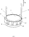
FIG. 1 is a structural perspective schematic view of a pouch packaged lithium-ion battery with a tooth-shaped sealing edge according to an embodiment of the present disclosure. -
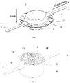
FIG. 2 is a structural perspective schematic view of a pouch packaged lithium-ion battery with a tooth-shaped sealing edge in an unfolded state according to an embodiment of the present disclosure. -
FIG. 3 is a structural schematic view of a jelly roll of a pouch packaged lithium-ion battery with a tooth-shaped sealing edge according to an embodiment of the present disclosure. -
FIG. 4 is a structural perspective schematic view of a pouch packaged lithium-ion battery with a tooth-shaped sealing edge according to another embodiment of the present disclosure. -
FIG. 5 is a structural perspective schematic view of a pouch packaged lithium-ion battery with a tooth-shaped sealing edge in an unfolded state according to another embodiment of the present disclosure. - Technical solutions of embodiments of the present disclosure will be clearly and completely described as follows in combination with the drawings in the embodiments of the present disclosure.
- As shown in
FIGS. 1-3 , the embodiment provides a pouch packaged lithium-ion battery with a tooth-shaped sealing edge, including amain body 7. Themain body 7 includes an aluminum-plastic film 8 with good insulativity. The aluminum-plastic film 8 defines a cavity where ajelly roll 4 is arranged therein. Thejelly roll 4 includes acathode 1, ananode 2 and afilm 3 separating thecathode 1 and theanode 2. Thecathode 1, thefilm 3 and theanode 2 are winded and overlaid to form a shape of cylinder substantially. That is, thejelly roll 4 is formed by winding and overlaying in an order: thecathode 1, thefilm 3, theanode 2, and thefilm 3. Acathode tab 5 and ananode tab 6 are respectively arranged on both sides of thejelly roll 4. Thecathode tab 5 is connected to thecathode 1 electrically, and theanode tab 6 is connected to theanode 2 electrically. A joint between thecathode tab 5 and thecathode 1 and a joint between theanode tab 6 and theanode 2 may be fixed by welding so that both thecathode 1 and theanode 2 can conduct electricity. A part of the aluminum-plastic film 8 in contact with thecathode tab 5 and theanode tab 6 is bent and extends toward an outside of the lithium-ion battery to form a sealingedge 10 in the middle of the main body 7 (that is, a first bending happens). After covering and wrapping thejelly roll 4 as shown inFIG. 3 , the sealingedge 10 and aluminum-plastic film 8 are sealed and molded by hot-pressing. Specifically, as shown inFIG. 2 , thecathode tab 5 and theanode tab 6 extend horizontally and penetrate thesealing edge 10. That is, after thecathode tab 5 and theanode tab 6 penetrate the sealingedge 10, the sealingedge 10 may be divided into 2 layers in a thickness direction, and thecathode tab 5 and theanode tab 6 are sandwiched between the 2 layers. A joint between thecathode 5 and the sealingedge 10 is covered with atab sealant 9. A joint between theanode tab 6 and the sealingedge 10 is also covered with thetab sealant 9. As shown inFIG. 1 , thesealing edge 10, thecathode tab 5 and theanode tab 6 may be bent upward to attach to a surface of the main body 7 (that is, a second bending happens). In the process of assembly, thecathode 1 andanode 2 are assembled in the sealing aluminum-plastic film 8 formed by stamping, that is, thejelly roll 4 is assembled in the sealing aluminum-plastic film 8 formed by stamping, and an upper portion and a lower portion of the aluminumplastic film 8 are sealed together by hot pressing. After thejelly roll 4 is injected with electrolyte, activated and sealed again, the sealingedge 10 on an outside of thejelly roll 4 is bent axially, so that the sealingedge 10 may attach to themain body 7 tightly. Moreover, the width of the sealingedge 10 in a diameter direction may be reduced, that is, the diameter of the battery may be reduced by 3-5mm. The energy density of the battery may be improved. Thecathode tab 5 and theanode tab 6 of the battery extend out themain body 7 at a radial angle of 45° - 90° to protect the assembly and connection of a printed circuit board (PCB). Since the sealingedge 10 is bent to the main body, the whole battery may be thus assembled to an inside of products of customers, which is convenient and efficient. The surface of the sealingedge 10 may be arranged withgrooves 13. Thegrooves 13 may be tooth-shaped in appearance and distributed in an annular array, so that the sealingedge 10 after bent and attached to themain body 7 is symmetrical, tidy and regular, and occurrences of random distribution of teeth and fold rebounding automatically formed after bending without insection may be limited. - An end of the
cathode tab 5 close to thejelly roll 4 may be arranged with afirst clamping part 11 in an inverted U type (that is, thefirst clamping part 11 defines an opening to match an edge of the jelly roll 4). Thefirst clamping part 11 and thecathode tab 5 are formed integrally by stamping. - The
first clamping part 11 is fixed to thecathode 1 by welding, so that the joint is strong and can conduct electricity. - An end of the
anode tab 6 close to thejelly roll 4 may be arranged with asecond clamping part 12 in an inverted U type (that is, thefirst clamping part 11 defines an opening to match an edge of the jelly roll 4). Thesecond clamping part 12 and theanode tab 6 are formed integrally by stamping. - The
second clamping part 12 is fixed to theanode 2 by welding, so that the joint is strong and can conduct electricity. - The
film 3 includes two layers. One layer is arranged on an outside of thecathode 1 and the other layer is arranged on an outside of theanode 2, which can at least limit the short circuit since thecathode 1 cannot contact with theanode 2 directly after winding. - A joint between the sealing
edge 10 and themain body 7 may be coated with asealant 14, so that the sealingedge 10 cannot rebound after bending, ensuring a firm structure thereof. - It can be seen that the
cathode tab 5 and theanode tab 6 may be symmetrically distributed on both sides of thejelly roll 4. - As shown in
FIGS. 4-5 , in order to reduce production cost, the tooth-shapedgrooves 13 on the surface of sealingedge 10 inembodiment 1 as shown inFIGS. 1-3 are omitted. The pouch packaged lithium-ion battery with a tooth-shaped sealing edge in theembodiment 2 as shown inFIGS. 4-5 includes: a pouch packaged lithium-ion battery with a jelly roll, including amain body 7. Themain body 7 includes an aluminum-plastic film 8 with good insulativity. The aluminum-plastic film 8 defines a cavity where ajelly roll 4 is arranged therein. Thejelly roll 4 includes acathode 1, ananode 2 and afilm 3 separating thecathode 1 and theanode 2. Thecathode 1, thefilm 3 and theanode 2 are winded and overlaid to form a shape of cylinder substantially. That is, thejelly roll 4 is formed by winding and overlaying in an order: thecathode 1, thefilm 3, theanode 2, and thefilm 3. Acathode tab 5 and ananode tab 6 are respectively arranged on both sides of thejelly roll 4. Thecathode tab 5 is connected to thecathode 1 electrically, and theanode tab 6 is connected to theanode 2 electrically. A joint between thecathode tab 5 and thecathode 1 and a joint between theanode tab 6 and theanode 2 may be fixed by welding so that both thecathode 1 and theanode 2 can conduct electricity. A part of the aluminum-plastic film 8 in contact with thecathode tab 5 and theanode tab 6 is bent and extends toward an outside of the lithium-ion battery to form a sealingedge 10 in the middle of the main body 7 (that is, a first bending happens). After covering and wrapping thejelly roll 4, the sealingedge 10 and aluminum-plastic film 8 are sealed and molded by hot-pressing. Specifically, as shown inFIG. 5 , thecathode tab 5 and theanode tab 6 extend horizontally and penetrate the sealingedge 10. A joint between thecathode 5 and the sealingedge 10 is covered with atab sealant 9. A joint between theanode tab 6 and the sealingedge 10 is also covered with thetab sealant 9. As shown inFIG. 4 , the sealingedge 10, thecathode tab 5 and theanode tab 6 may be bent upward to attach to a surface of the main body 7 (that is, a second bending happens). In the process of assembly, thecathode 1 andanode 2 are assembled in the sealing aluminum-plastic film 8 formed by stamping, that is, thejelly roll 4 is assembled in the sealing aluminum-plastic film 8 formed by stamping, and an upper portion and a lower portion of thealuminum plastic film 8 are sealed together by hot pressing. After thejelly roll 4 is injected with electrolyte, activated and sealed again, the sealingedge 10 on an outside of thejelly roll 4 is bent axially, so that the sealingedge 10 may attach to themain body 7 tightly. Moreover, the width of the sealingedge 10 in a diameter direction may be reduced, that is, the diameter of the battery may be reduced by 3-5mm. The energy density of the battery may be improved. Thecathode tab 5 and theanode tab 6 of the battery extend out themain body 7 at a radial angle of 45° - 90° to protect the assembly and connection of the PCB. Since the sealingedge 10 is bent to the main body, the whole battery may be thus assembled to an inside of products of customers, which is convenient and efficient. - In conclusion, by virtue of the technical solutions above, the present disclosure may achieve beneficial effects as followed. The cathode, the film and the anode are winded and overlaid to form a shape of cylinder substantially. That is, the jelly roll is formed by winding and overlaying in an order: the cathode, the film, the anode, and the film, therefore the film between the cathode and the anode can at least limit the occurrence of a short. The integral structure of the jelly roll is compact after wending, thereby improving the energy density of the battery. The cathode tab and the anode tab extend horizontally and penetrate the sealing edge. A joint between the cathode and the sealing edge is covered with a tab sealant, and a joint between the anode tab and the sealing edge is also covered with the tab sealant. Since the sealing edge, the cathode tab and the anode tab are bent upward to attach to a surface of the main body, the width of the sealing edge in a diameter direction may be thus reduced. The cathode tab and the anode tab are convenient to be connected to a circuit after extending upward, so that the whole battery may be thus conveniently assembled to an inside of products of customers. The surface of the sealing edge is arranged with grooves, and the grooves are tooth-shaped in appearance and distributed in an annular array, therefore a crease is incapable to be generate and the sealing edge after bent is regular and beautiful.
- The above embodiments are some optimized implantations of the present disclosure. It should be noted that, those skilled in the art can still make any improvements and modifications without departing from the idea of the present disclosure, and all these belong to the scope of the present disclosure.
Claims (9)
- A pouch packaged lithium-ion battery with a tooth-shaped sealing edge, characterized by comprising:
a main body (7), comprising an aluminum-plastic film (8); wherein the aluminum-plastic film (8) defines a cavity where a jelly roll (4) is arranged therein; the jelly roll (4) comprises a cathode (1), an anode (2) and a film (3) separating the cathode (1) and the anode (2); the cathode (1), the film (3) and the anode (2) are winded and overlaid to form a shape of cylinder substantially; a cathode tab (5) is arranged on a side of the jelly roll (4), and an anode tab (6) is arranged on the other side of the jelly roll (4); the cathode tab (5) is connected to the cathode (1) electrically, and the anode tab (6) is connected to the anode (2) electrically; a part of the aluminum-plastic film (8) in contact with the cathode tab (5) and the anode tab (6) is bent and extends toward an outside of the lithium-ion battery to form a sealing edge (10) in the middle of the main body (7); the cathode tab (5) and the anode tab (6) extend horizontally and penetrate the sealing edge (10); a joint between the cathode tab (5) and the sealing edge (10) is covered with a tab sealant (10), and a joint between the anode tab (6) and the sealing edge (10) is also covered with a tab sealant (10); the sealing edge (10), the cathode tab (5) and the anode tab (6) are bent upward to attach to a surface of the main body (7); a surface of the sealing edge (10) is arranged with grooves (13), and the grooves (13) are tooth-shaped in appearance and distributed in an annular array. - The pouch packaged lithium-ion battery with a tooth-shaped sealing edge according to claim 1, wherein an end of the cathode tab (5) close to the jelly roll (4) is arranged with a first clamping part (11) in an inverted U type.
- The pouch packaged lithium-ion battery with a tooth-shaped sealing edge according to claim 2, wherein the first clamping part (11) is fixed to the cathode (1) by welding.
- The pouch packaged lithium-ion battery with a tooth-shaped sealing edge to claim 1, wherein an end of the anode tab (6) close to the jelly roll (4) is arranged with a second clamping part (12) in an inverted U type.
- The pouch packaged lithium-ion battery with a tooth-shaped sealing edge according to claim 4, wherein the second clamping part (12) is fixed to the anode (2) by welding.
- The pouch packaged lithium-ion battery with a tooth-shaped sealing edge according to claim 1, wherein the film (3) comprises two layers, one layer is arranged on an outer side of the cathode (1) and the other layer is arranged on an outer side of the anode (2).
- The pouch packaged lithium-ion battery with a tooth-shaped sealing edge according to claim 1, wherein a joint between the sealing edge (10) and the main body (7) is coated with a sealant (14).
- The pouch packaged lithium-ion battery with a tooth-shaped sealing edge according to claim 1, wherein the cathode tab (5) and the anode tab (6) are symmetrically distributed on both sides of the jelly roll (4).
- The pouch packaged lithium-ion battery with a tooth-shaped sealing edge according to claim 1, wherein after the cathode tab (5) and the anode tab (6) are bent upward to attach to the surface of the main body (7), a radial angle between the cathode tab (5) and the main body (7) is 45° - 90° and a radial angle between the anode tab (6) and the main body (7) is also 45° - 90°.
Applications Claiming Priority (1)
| Application Number | Priority Date | Filing Date | Title |
|---|---|---|---|
| CN202120040153.4U CN216015452U (en) | 2021-01-07 | 2021-01-07 | Soft package lithium ion battery cell with insection sealing edge |
Publications (1)
| Publication Number | Publication Date |
|---|---|
| EP4027438A1 true EP4027438A1 (en) | 2022-07-13 |
Family
ID=77640476
Family Applications (1)
| Application Number | Title | Priority Date | Filing Date |
|---|---|---|---|
| EP21194842.7A Pending EP4027438A1 (en) | 2021-01-07 | 2021-09-03 | Pouch packaged lithium-ion battery with tooth-shaped sealing edge |
Country Status (6)
| Country | Link |
|---|---|
| US (1) | US11811077B2 (en) |
| EP (1) | EP4027438A1 (en) |
| JP (1) | JP3234817U (en) |
| KR (1) | KR102680856B1 (en) |
| CN (1) | CN216015452U (en) |
| DE (1) | DE202021104727U1 (en) |
Families Citing this family (2)
| Publication number | Priority date | Publication date | Assignee | Title |
|---|---|---|---|---|
| CN111129417B (en) * | 2019-12-30 | 2022-10-11 | 广东微电新能源有限公司 | Manufacturing method of soft package battery |
| CN115347246B (en) * | 2022-08-30 | 2024-07-23 | 厦门海辰储能科技股份有限公司 | Tab glue shaping jig monomer, tab glue shaping jig and shaping method |
Citations (5)
| Publication number | Priority date | Publication date | Assignee | Title |
|---|---|---|---|---|
| US20090165290A1 (en) * | 2006-07-14 | 2009-07-02 | Yu Si-Chul | Method of making battery using as case with aluminium multilayered films |
| CN109361010A (en) * | 2018-12-08 | 2019-02-19 | 广东维都利新能源有限公司 | A kind of discoid poly-lithium battery of takeup type and preparation method thereof |
| CN110197923A (en) * | 2019-04-23 | 2019-09-03 | 广东维都利新能源有限公司 | Button polymer lithium ion battery and circular waveform edge pressing mode thereof |
| CN110943257A (en) * | 2019-12-02 | 2020-03-31 | 广东维都利新能源有限公司 | A flexible packaging lithium ion battery folding forming equipment |
| CN112259920A (en) * | 2020-09-18 | 2021-01-22 | 广东维都利新能源有限公司 | Quick-connect soft-package button cell |
Family Cites Families (9)
| Publication number | Priority date | Publication date | Assignee | Title |
|---|---|---|---|---|
| KR100726065B1 (en) * | 2004-12-22 | 2007-06-08 | 에스케이 주식회사 | High power lithium battery packs with high power lithium cells and high power lithium cells |
| KR101453037B1 (en) | 2011-03-23 | 2014-10-21 | 주식회사 엘지화학 | Electrode assembly for secondary battery preparation method of electrode assembly thereof |
| KR20140117318A (en) * | 2014-08-22 | 2014-10-07 | 주식회사 엘지화학 | Electrode assembly having two type separators and Secondary Batteries comprising the same |
| US9929393B2 (en) | 2015-09-30 | 2018-03-27 | Apple Inc. | Wound battery cells with notches accommodating electrode connections |
| JP6681720B2 (en) | 2016-01-22 | 2020-04-15 | セイコーインスツル株式会社 | Electrochemical cell and method of manufacturing electrochemical cell |
| JP6284248B1 (en) | 2016-11-22 | 2018-02-28 | セイコーインスツル株式会社 | Electrochemical cell and method for producing electrochemical cell |
| CN210535760U (en) | 2019-08-14 | 2020-05-15 | 宁德时代新能源科技股份有限公司 | Electrode assemblies and secondary batteries |
| KR102818645B1 (en) * | 2019-08-19 | 2025-06-10 | 삼성에스디아이 주식회사 | Rechargeable battery |
| CN110729447A (en) | 2019-10-09 | 2020-01-24 | 惠州锂威新能源科技有限公司 | Battery cell pole piece and battery cell |
-
2021
- 2021-01-07 CN CN202120040153.4U patent/CN216015452U/en active Active
- 2021-07-02 US US17/366,090 patent/US11811077B2/en active Active
- 2021-08-25 KR KR1020210112286A patent/KR102680856B1/en active Active
- 2021-08-27 JP JP2021003335U patent/JP3234817U/en active Active
- 2021-09-02 DE DE202021104727.5U patent/DE202021104727U1/en active Active
- 2021-09-03 EP EP21194842.7A patent/EP4027438A1/en active Pending
Patent Citations (5)
| Publication number | Priority date | Publication date | Assignee | Title |
|---|---|---|---|---|
| US20090165290A1 (en) * | 2006-07-14 | 2009-07-02 | Yu Si-Chul | Method of making battery using as case with aluminium multilayered films |
| CN109361010A (en) * | 2018-12-08 | 2019-02-19 | 广东维都利新能源有限公司 | A kind of discoid poly-lithium battery of takeup type and preparation method thereof |
| CN110197923A (en) * | 2019-04-23 | 2019-09-03 | 广东维都利新能源有限公司 | Button polymer lithium ion battery and circular waveform edge pressing mode thereof |
| CN110943257A (en) * | 2019-12-02 | 2020-03-31 | 广东维都利新能源有限公司 | A flexible packaging lithium ion battery folding forming equipment |
| CN112259920A (en) * | 2020-09-18 | 2021-01-22 | 广东维都利新能源有限公司 | Quick-connect soft-package button cell |
Also Published As
| Publication number | Publication date |
|---|---|
| JP3234817U (en) | 2021-11-04 |
| KR20220099883A (en) | 2022-07-14 |
| US11811077B2 (en) | 2023-11-07 |
| KR102680856B1 (en) | 2024-07-02 |
| DE202021104727U1 (en) | 2021-09-09 |
| US20220216542A1 (en) | 2022-07-07 |
| CN216015452U (en) | 2022-03-11 |
Similar Documents
| Publication | Publication Date | Title |
|---|---|---|
| KR100627313B1 (en) | Secondary battery | |
| EP2500972B1 (en) | Lithium secondary battery having multi-directional lead-tab structure | |
| JP5505218B2 (en) | Sealed storage battery | |
| US9318735B2 (en) | Terminal-attached plate, plate assembly, and battery module | |
| KR20050121907A (en) | Secondary battery and electrodes assembly using the same | |
| US20060008701A1 (en) | Electrode assembly and lithium ion secondary battery using the same | |
| CA2259769A1 (en) | Thin type sealed cell and producing method thereof | |
| KR100627360B1 (en) | Collector plate and its secondary battery and battery module | |
| JP2004356085A (en) | Jelly roll type electrode assembly and secondary battery using this | |
| KR101165287B1 (en) | A soft packaged and high capacity lithium ion battery and the manufacture method of the same | |
| US10158107B2 (en) | Battery comprising insulative films | |
| US20060099501A1 (en) | Secondary battery | |
| EP4027438A1 (en) | Pouch packaged lithium-ion battery with tooth-shaped sealing edge | |
| US20240136681A1 (en) | Battery covers and power batteries | |
| CN218039736U (en) | Lithium ion battery and battery pack | |
| JP5768002B2 (en) | Secondary battery | |
| CN222735136U (en) | Battery cells, batteries and electrical devices | |
| JP3869668B2 (en) | Electrochemical device and manufacturing method thereof | |
| KR101095343B1 (en) | Jelly-roll with improved structure and secondary battery comprising the same | |
| CN221747291U (en) | Battery cell and battery | |
| KR100590009B1 (en) | Secondary Battery and Electrode Assembly Used in the Same | |
| JP2001266812A (en) | Non-aqueous secondary battery | |
| CN218975511U (en) | Battery cell packaging film, battery and electricity utilization device | |
| CN215933698U (en) | Casing subassembly and battery | |
| JP2006286471A (en) | Battery manufacturing method and battery |
Legal Events
| Date | Code | Title | Description |
|---|---|---|---|
| PUAI | Public reference made under article 153(3) epc to a published international application that has entered the european phase |
Free format text: ORIGINAL CODE: 0009012 |
|
| STAA | Information on the status of an ep patent application or granted ep patent |
Free format text: STATUS: THE APPLICATION HAS BEEN PUBLISHED |
|
| AK | Designated contracting states |
Kind code of ref document: A1 Designated state(s): AL AT BE BG CH CY CZ DE DK EE ES FI FR GB GR HR HU IE IS IT LI LT LU LV MC MK MT NL NO PL PT RO RS SE SI SK SM TR |
|
| STAA | Information on the status of an ep patent application or granted ep patent |
Free format text: STATUS: REQUEST FOR EXAMINATION WAS MADE |
|
| 17P | Request for examination filed |
Effective date: 20221114 |
|
| RBV | Designated contracting states (corrected) |
Designated state(s): AL AT BE BG CH CY CZ DE DK EE ES FI FR GB GR HR HU IE IS IT LI LT LU LV MC MK MT NL NO PL PT RO RS SE SI SK SM TR |
|
| STAA | Information on the status of an ep patent application or granted ep patent |
Free format text: STATUS: EXAMINATION IS IN PROGRESS |
|
| 17Q | First examination report despatched |
Effective date: 20240902 |