EP4027436A1 - Box body, battery pack, and apparatus - Google Patents
Box body, battery pack, and apparatus Download PDFInfo
- Publication number
- EP4027436A1 EP4027436A1 EP20929153.3A EP20929153A EP4027436A1 EP 4027436 A1 EP4027436 A1 EP 4027436A1 EP 20929153 A EP20929153 A EP 20929153A EP 4027436 A1 EP4027436 A1 EP 4027436A1
- Authority
- EP
- European Patent Office
- Prior art keywords
- shielding member
- box
- battery pack
- bulge
- hollow portion
- Prior art date
- Legal status (The legal status is an assumption and is not a legal conclusion. Google has not performed a legal analysis and makes no representation as to the accuracy of the status listed.)
- Pending
Links
- 230000004308 accommodation Effects 0.000 claims abstract description 12
- 238000004146 energy storage Methods 0.000 abstract description 2
- 238000010586 diagram Methods 0.000 description 8
- 230000003014 reinforcing effect Effects 0.000 description 3
- 229910000838 Al alloy Inorganic materials 0.000 description 2
- 229910052782 aluminium Inorganic materials 0.000 description 2
- XAGFODPZIPBFFR-UHFFFAOYSA-N aluminium Chemical compound [Al] XAGFODPZIPBFFR-UHFFFAOYSA-N 0.000 description 2
- 230000000712 assembly Effects 0.000 description 2
- 238000000429 assembly Methods 0.000 description 2
- 230000015572 biosynthetic process Effects 0.000 description 2
- 239000007769 metal material Substances 0.000 description 2
- 230000000116 mitigating effect Effects 0.000 description 2
- 239000000243 solution Substances 0.000 description 2
- 230000005540 biological transmission Effects 0.000 description 1
- 238000004891 communication Methods 0.000 description 1
- 230000000694 effects Effects 0.000 description 1
- 239000008151 electrolyte solution Substances 0.000 description 1
- 239000012774 insulation material Substances 0.000 description 1
- 238000005192 partition Methods 0.000 description 1
- 230000002787 reinforcement Effects 0.000 description 1
- 238000007789 sealing Methods 0.000 description 1
- 238000004804 winding Methods 0.000 description 1
Images


Classifications
-
- H—ELECTRICITY
- H01—ELECTRIC ELEMENTS
- H01M—PROCESSES OR MEANS, e.g. BATTERIES, FOR THE DIRECT CONVERSION OF CHEMICAL ENERGY INTO ELECTRICAL ENERGY
- H01M50/00—Constructional details or processes of manufacture of the non-active parts of electrochemical cells other than fuel cells, e.g. hybrid cells
- H01M50/20—Mountings; Secondary casings or frames; Racks, modules or packs; Suspension devices; Shock absorbers; Transport or carrying devices; Holders
-
- H—ELECTRICITY
- H01—ELECTRIC ELEMENTS
- H01M—PROCESSES OR MEANS, e.g. BATTERIES, FOR THE DIRECT CONVERSION OF CHEMICAL ENERGY INTO ELECTRICAL ENERGY
- H01M50/00—Constructional details or processes of manufacture of the non-active parts of electrochemical cells other than fuel cells, e.g. hybrid cells
- H01M50/20—Mountings; Secondary casings or frames; Racks, modules or packs; Suspension devices; Shock absorbers; Transport or carrying devices; Holders
- H01M50/233—Mountings; Secondary casings or frames; Racks, modules or packs; Suspension devices; Shock absorbers; Transport or carrying devices; Holders characterised by physical properties of casings or racks, e.g. dimensions
- H01M50/242—Mountings; Secondary casings or frames; Racks, modules or packs; Suspension devices; Shock absorbers; Transport or carrying devices; Holders characterised by physical properties of casings or racks, e.g. dimensions adapted for protecting batteries against vibrations, collision impact or swelling
-
- H—ELECTRICITY
- H01—ELECTRIC ELEMENTS
- H01M—PROCESSES OR MEANS, e.g. BATTERIES, FOR THE DIRECT CONVERSION OF CHEMICAL ENERGY INTO ELECTRICAL ENERGY
- H01M50/00—Constructional details or processes of manufacture of the non-active parts of electrochemical cells other than fuel cells, e.g. hybrid cells
- H01M50/20—Mountings; Secondary casings or frames; Racks, modules or packs; Suspension devices; Shock absorbers; Transport or carrying devices; Holders
- H01M50/204—Racks, modules or packs for multiple batteries or multiple cells
- H01M50/207—Racks, modules or packs for multiple batteries or multiple cells characterised by their shape
- H01M50/209—Racks, modules or packs for multiple batteries or multiple cells characterised by their shape adapted for prismatic or rectangular cells
-
- H—ELECTRICITY
- H01—ELECTRIC ELEMENTS
- H01M—PROCESSES OR MEANS, e.g. BATTERIES, FOR THE DIRECT CONVERSION OF CHEMICAL ENERGY INTO ELECTRICAL ENERGY
- H01M50/00—Constructional details or processes of manufacture of the non-active parts of electrochemical cells other than fuel cells, e.g. hybrid cells
- H01M50/20—Mountings; Secondary casings or frames; Racks, modules or packs; Suspension devices; Shock absorbers; Transport or carrying devices; Holders
- H01M50/244—Secondary casings; Racks; Suspension devices; Carrying devices; Holders characterised by their mounting method
-
- H—ELECTRICITY
- H01—ELECTRIC ELEMENTS
- H01M—PROCESSES OR MEANS, e.g. BATTERIES, FOR THE DIRECT CONVERSION OF CHEMICAL ENERGY INTO ELECTRICAL ENERGY
- H01M50/00—Constructional details or processes of manufacture of the non-active parts of electrochemical cells other than fuel cells, e.g. hybrid cells
- H01M50/20—Mountings; Secondary casings or frames; Racks, modules or packs; Suspension devices; Shock absorbers; Transport or carrying devices; Holders
- H01M50/249—Mountings; Secondary casings or frames; Racks, modules or packs; Suspension devices; Shock absorbers; Transport or carrying devices; Holders specially adapted for aircraft or vehicles, e.g. cars or trains
-
- H—ELECTRICITY
- H01—ELECTRIC ELEMENTS
- H01M—PROCESSES OR MEANS, e.g. BATTERIES, FOR THE DIRECT CONVERSION OF CHEMICAL ENERGY INTO ELECTRICAL ENERGY
- H01M2220/00—Batteries for particular applications
- H01M2220/20—Batteries in motive systems, e.g. vehicle, ship, plane
-
- H—ELECTRICITY
- H01—ELECTRIC ELEMENTS
- H01M—PROCESSES OR MEANS, e.g. BATTERIES, FOR THE DIRECT CONVERSION OF CHEMICAL ENERGY INTO ELECTRICAL ENERGY
- H01M50/00—Constructional details or processes of manufacture of the non-active parts of electrochemical cells other than fuel cells, e.g. hybrid cells
- H01M50/20—Mountings; Secondary casings or frames; Racks, modules or packs; Suspension devices; Shock absorbers; Transport or carrying devices; Holders
- H01M50/218—Mountings; Secondary casings or frames; Racks, modules or packs; Suspension devices; Shock absorbers; Transport or carrying devices; Holders characterised by the material
- H01M50/22—Mountings; Secondary casings or frames; Racks, modules or packs; Suspension devices; Shock absorbers; Transport or carrying devices; Holders characterised by the material of the casings or racks
- H01M50/222—Inorganic material
- H01M50/224—Metals
-
- H—ELECTRICITY
- H01—ELECTRIC ELEMENTS
- H01M—PROCESSES OR MEANS, e.g. BATTERIES, FOR THE DIRECT CONVERSION OF CHEMICAL ENERGY INTO ELECTRICAL ENERGY
- H01M50/00—Constructional details or processes of manufacture of the non-active parts of electrochemical cells other than fuel cells, e.g. hybrid cells
- H01M50/20—Mountings; Secondary casings or frames; Racks, modules or packs; Suspension devices; Shock absorbers; Transport or carrying devices; Holders
- H01M50/258—Modular batteries; Casings provided with means for assembling
-
- Y—GENERAL TAGGING OF NEW TECHNOLOGICAL DEVELOPMENTS; GENERAL TAGGING OF CROSS-SECTIONAL TECHNOLOGIES SPANNING OVER SEVERAL SECTIONS OF THE IPC; TECHNICAL SUBJECTS COVERED BY FORMER USPC CROSS-REFERENCE ART COLLECTIONS [XRACs] AND DIGESTS
- Y02—TECHNOLOGIES OR APPLICATIONS FOR MITIGATION OR ADAPTATION AGAINST CLIMATE CHANGE
- Y02E—REDUCTION OF GREENHOUSE GAS [GHG] EMISSIONS, RELATED TO ENERGY GENERATION, TRANSMISSION OR DISTRIBUTION
- Y02E60/00—Enabling technologies; Technologies with a potential or indirect contribution to GHG emissions mitigation
- Y02E60/10—Energy storage using batteries
Definitions
- This application relates to the technical field of batteries, and in particular, to a box, a battery pack, and a device.
- a hitch part of the battery pack is a boundary of the battery pack.
- the hitch part safeguards performance and integrity of the battery pack, and is essential to safety of a vehicle.
- the hitch part of the battery pack is exposed to the outside of the battery pack. Therefore, when the vehicle loses control or collides, the hitch part is most vulnerable to failure. Consequently, the battery pack is squeezed, and safety performance of the battery pack and the vehicle is inferior.
- This application provides a box, a battery pack, and a device to mitigate the problem that a hitch part of the battery pack is vulnerable to failure when a vehicle collides.
- a first aspect of the embodiments of this application provides a box.
- the box includes:
- the shielding member includes a first shielding member and a second shielding member.
- the first shielding member and the second shielding member are connected to each other to form the hollow portion.
- the shielding member with a hollow portion is disposed, even if a vehicle is squeezed in a lateral collision, the shielding member is squeezed first, and the shielding member withstands a squeezing force.
- the hollow portion disposed in the shielding member serves functions of absorbing and cushioning the squeezing force in the lateral collision, thereby increasing the capability of resisting the squeezing force in the lateral collision and effectively safeguarding the performance and soundness of the battery pack. This mitigates the problem that a hitch part of the battery pack is vulnerable to failure when a vehicle collides, and improves safety performance of the battery pack and the vehicle.
- first shielding member and the second shielding member are disposed separately, so as to achieve the advantage of high strength in comparison with the integrally formed shielding member.
- the first shielding member and the second shielding member are disposed independently, and a joint between the first shielding member and the second shielding member can withstand a relatively high squeezing force, thereby significantly improving the capability of the shielding member to resist the squeezing force in a lateral collision.
- the fixing member is connected to a periphery of the frame member.
- the fixing member is connected to the periphery of the frame member.
- the shielding member is configured to be connected to the frame member.
- the hollow portion contained in the shielding member accommodates at least a part of the fixing member. In this way, both the fixing member and the shielding member are connected to the periphery of the frame member. Therefore, even if a vehicle is squeezed in a lateral collision, the shielding member is squeezed firstly, and the shielding member withstands a squeezing force.
- the hollow portion disposed in the shielding member serves functions of absorbing and cushioning the squeezing force in the lateral collision, thereby increasing the capability of resisting the squeezing force in the lateral collision and effectively safeguarding the performance and soundness of the battery pack.
- the first shielding member includes a first bulge.
- the first bulge is disposed to protrude away from the second shielding member.
- the first bulge and a corresponding part of the second shielding member form the hollow portion.
- the first bulge is disposed to protrude away from the second shielding member to facilitate formation of the hollow portion configured to accommodate the fixing member.
- the first bulge can increase strength of the first shielding member, thereby increasing the strength of the entire shielding member, improving the capability of resisting a squeezing force in a lateral collision, and effectively safeguarding the performance and soundness of the battery pack.
- the second shielding member includes a second bulge, and the second bulge is disposed to protrude toward the first shielding member.
- the provision of the second bulge can increase the strength of the second shielding member, thereby increasing the strength of the entire shielding member.
- the second bulge is disposed to protrude toward the first shielding member, thereby downsizing the entire shielding member and downsizing the entire battery pack.
- the second bulge fits snugly with the first shielding member.
- the second bulge fits snugly with the first shielding member, thereby increasing the strength of the close-fitting position.
- the shielding member at the close-fitting position is not likely to deform, thereby improving the capability of resisting a squeezing force in a lateral collision and safeguarding the safety performance of the battery pack.
- the fixing member includes a hitch portion configured to fix the box, and the hitch portion is accommodated in the hollow portion.
- the hitch portion in this embodiment is configured to hitch the box onto the vehicle.
- the hitch portion is accommodated in the hollow portion.
- the hollow portion can serve a cushioning function and avoid the hitch portion to collide directly, thereby improving the capability of the battery pack to resist the squeezing force in a lateral collision.
- a top of the hitch portion fits snugly with the shielding member; and/or a bottom of the hitch portion fits snugly with the shielding member.
- the top or bottom of the hitch portion fits snugly with the shielding member to serve a function of supporting the hollow portion.
- both the top and bottom of the hitch portion fit snugly with the shielding member.
- the hitch portion is located in the hollow portion. Therefore, the hitch portion and the shielding member fit snugly together to serve a function of supporting the hollow portion, and increase the strength of the shielding member.
- the hitch portion includes a third bulge.
- the third bulge is disposed to protrude toward the first shielding member. A gap exists between the third bulge and the first shielding member.
- the provision of the third bulge can increase the strength of the hitch portion.
- a protrusion direction of the third bulge is consistent with a protrusion direction of the first bulge, thereby leaving the space for the shielding member.
- the gap is configured to install a bushing.
- a second aspect of the embodiments of this application provides a battery pack.
- the battery pack includes: the box; and a battery accommodated in an accommodation cavity of the box.
- the battery pack in this embodiment includes the box, thereby effectively safeguarding the performance and soundness of the battery pack, mitigating the problem that a hitch part of the battery pack is vulnerable to failure when a vehicle collides, and improving safety performance of the battery pack and the vehicle.
- a third aspect of the embodiments of this application provides a device.
- the device includes the battery pack configured to provide electrical energy.
- the device in this embodiment adopts the battery pack described above, thereby effectively safeguarding the performance and soundness of the battery pack, mitigating the problem that the hitch part of the battery pack is vulnerable to failure when the vehicle collides, and improving the safety performance of the battery pack and the vehicle.
- a plurality of means two or more; the terms such as “upper”, “lower”, “left”, “right”, “inner”, and “outer” indicating a direction or a position relationship are merely intended for ease or brevity of description of this application, but do not indicate or imply that the device or component referred to must be located in the specified direction or constructed or operated in the specified direction. Therefore, such terms shall not be understood as a limitation on this application.
- the terms “first”, “second”, and “third” are merely intended for descriptive purposes, but are not intended to indicate or imply relative importance.
- Perfect is not exactly perpendicular, but within an error tolerance range.
- Parallel is not exactly parallel, but within an error tolerance range.
- connection may be a fixed connection, a detachable connection, or an integrated connection, and may be a direct connection or an indirect connection implemented through an intermediary.
- FIG. 1 is a schematic structural diagram of a device according to an embodiment of this application
- FIG. 2 is a schematic structural diagram of a battery pack P according to an embodiment of this application.
- the device may be a mobile device such as a vehicle, an energy storage cabinet, a ship, or a small aircraft.
- the device includes a power source, and the power source is configured to provide a driving force for the device.
- the driving force of the device may be sole electrical energy, or may include electrical energy and other types of energy (such as mechanical energy).
- the power source may be a battery module L (or a battery pack P), or may be a combination of a battery module L (or battery pack P) and an engine, or the like. Therefore, all devices powered by a battery module L (or battery pack P) fall within the protection scope of this application.
- a vehicle may be a new energy vehicle.
- the new energy vehicle may be a battery electric vehicle, or may be a hybrid electric vehicle, a range-extended electric vehicle, or the like.
- the vehicle may include a battery pack P and a vehicle body.
- the battery pack P is disposed in the vehicle body.
- a driving motor is further disposed in the vehicle body, and the driving motor is electrically connected to the battery pack P.
- the battery pack P provides electrical energy.
- the driving motor is connected to wheels of the vehicle body through a transmission mechanism to drive the vehicle to move.
- the battery pack P may be horizontally disposed at a bottom of the vehicle body.
- a battery pack P includes a box M and a battery module L disposed in the box M.
- the battery module L includes a plurality of batteries.
- the batteries may be rechargeable secondary batteries.
- the plurality of batteries are located in an inner cavity of the box M and stacked together in the inner cavity along a length direction, a width direction or a height direction.
- Each of the batteries includes an electrode assembly, a cap assembly, and a housing.
- the housing may be hexahedral or other shapes.
- a cavity is formed inside the housing to accommodate the electrode assembly and an electrolytic solution.
- the electrode assembly is formed by winding or stacking a positive electrode plate, a negative electrode plate, and a separator.
- One end of the housing opens so that the electrode assembly can be placed into the cavity of the housing through the opening.
- a plurality of electrode assemblies may be disposed in the cavity. The plurality of electrode assemblies are stacked together.
- the housing may include a metal material, such as aluminum or an aluminum alloy, or may include an insulation material such as plastic.
- the box M is a structure the top of which opens, and includes an upper box cover.
- the size of the upper box cover is equivalent to the size of the opening at the top of the box M.
- the upper box cover may be fixed to the opening by a fastener such as a bolt.
- a sealing element may be disposed between the upper box cover and the box M.
- the box M may be made of aluminum, aluminum alloy or other metal materials.
- the box M contains an accommodation cavity 11.
- the accommodation cavity 11 can accommodate a plurality of batteries.
- the plurality of batteries may form battery modules L.
- the battery modules L may be arranged alongside along a length direction (X) of the battery pack P in the box M, or may be arranged alongside along a width direction (Y) of the battery pack P. Each battery module L is fixed to the box M.
- a hitch part of the battery pack P is a boundary of the battery pack P, and is most vulnerable to failure when a vehicle collides.
- the hitch part is exposed to the outside of the battery pack P and is not protected due to lack of a shielding structure. Therefore, when the vehicle loses control or collides, the hitch part is most prone to deform by a collision.
- the collision squeezes the box M and further squeezes the battery module L, thereby causing danger and impairing safety performance.
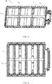
- FIG. 3 is a schematic structural diagram of a box M according to an embodiment of this application;
- FIG. 4 is a bottom view of a box M according to an embodiment of this application;
- FIG. 5 is a sectional view of FIG. 4 sectioned along an A-A line.
- this embodiment provides a box M for a battery pack P.
- the box M includes a frame member 1, a fixing member 3, and a shielding member 2.
- the frame member 1 is configured to form an accommodation cavity 11.
- the fixing member 3 is configured to mount the box M.
- the fixing member 3 is connected to the frame member 1.
- the shielding member 2 is configured to be connected to the frame member 1.
- the shielding member 2 includes a hollow portion 23.
- At least a part of the fixing member 3 is accommodated in the hollow portion 23.
- the provision of the shielding member 2 with a hollow portion 23 mitigates the problem that a hitch part of the battery pack P is vulnerable to failure when a vehicle collides, and improves safety performance of the battery pack P and the vehicle.
- the fixing member 3 is configured to hitch the frame member 1 onto the vehicle to form a hitch part of the battery pack P.
- the fixing member 3 is squeezed, and then the frame member 1 and the battery module L are squeezed. Therefore, the shielding member 2 with a hollow portion 23 is disposed.
- the hollow portion 23 of the shielding member 2 accommodates at least a part of the fixing member 3 to protect the fixing member 3. Therefore, when the vehicle is squeezed in a lateral collision, the shielding member 2 is squeezed first, and the shielding member 2 withstands a squeezing force.
- the hollow portion 23 disposed in the shielding member 2 serves functions of absorbing and cushioning the squeezing force, thereby increasing the capability of resisting the squeezing force in the lateral collision and effectively safeguarding the performance and soundness of the battery pack P and improving safety performance of the vehicle.
- a reinforcing plate 12 is disposed at the bottom of the frame member 1, and is configured to support the battery module L and serve a function of reinforcement.
- the fixing member 3 is a structure formed by extending the reinforcing plate 12 along the width direction (Y) of the box M.
- the box M includes a crossbeam 13 and a vertical beam 14.
- the crossbeam 13 and the vertical beam 14 partition the frame member 1 into a plurality of accommodation cavities 11. Each of the accommodation cavities 11 can accommodate the battery module L.
- the crossbeam 13 and the vertical beam 14 are fixedly connected to the battery module L separately, so that the battery module L is fixed in the accommodation cavity 11 of the box M to prevent the battery module L from loosening.
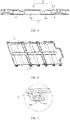
- FIG. 8 is a top view of a first shielding member 21 of a box M according to an embodiment of this application
- FIG. 9 is a bottom view of a second shielding member 22 of a box M according to an embodiment of this application
- FIG. 10 is a local detailed view of a part of FIG. 9 .
- the shielding member 2 according to this embodiment of this application includes a first shielding member 21 and a second shielding member 22.
- the first shielding member 21 and the second shielding member 22 are connected to each other to form a hollow portion 23.
- the first shielding member 21 and the second shielding member 22 are arranged from top downward to form a hollow portion 23 configured to accommodate the fixing member 3.
- the first shielding member 21 and the second shielding member 22 are disposed separately, so as to achieve the advantage of high strength in comparison with the integrally formed shielding member 2.
- the first shielding member 21 and the second shielding member 22 are disposed separately, and a joint between the first shielding member 21 and the second shielding member 22 can withstand a relatively high squeezing force, thereby significantly improving the capability of the shielding member 2 in resisting the squeezing force in a lateral collision.
- the first shielding member 21 includes a first connecting piece 213, and the second shielding member 22 includes a second connecting piece 224.
- the first connecting piece 213 is connected to the second connecting piece 224 to form the shielding member 2.
- the two connecting pieces can improve the capability of the shielding member 2 to withstand a squeezing force.
- the first connecting piece 213 and the second connecting piece 224 are fixedly connected to the frame member 1 separately to fix the first shielding member 21 and the second shielding member 22 onto the box M respectively, thereby improving the structural strength.
- the first shielding member 21 includes a first bulge 211.
- the first bulge 211 is disposed to protrude away from the second shielding member 22.
- the first bulge 211 and a corresponding part of the second shielding member 22 form a hollow portion 23.
- the first bulge 211 is disposed to protrude away from the second shielding member 22 to facilitate formation of the hollow portion 23 configured to accommodate the fixing member 3.
- the first bulge 211 can increase strength of the first shielding member 21, thereby increasing the strength of the entire shielding member 2, improving the capability of resisting a squeezing force in a lateral collision, and effectively safeguarding the performance and soundness of the battery pack P.
- the second shielding member 22 includes a second bulge 222.
- the second bulge 222 is disposed to protrude toward the first shielding member 21.
- the second bulge 222 can increase the strength of the second shielding member 22, thereby increasing the strength of the entire shielding member 2.
- the second bulge 222 is disposed to protrude toward the first shielding member 21, thereby downsizing the entire shielding member 2 and downsizing the entire battery pack P.
- the second bulge 222 fits snugly with the first shielding member 21, thereby increasing the strength of the close-fitting position. After being squeezed in a lateral collision, the shielding member 2 at the close-fitting position is not likely to deform, thereby improving the capability of resisting a squeezing force in a lateral collision and safeguarding the safety performance of the battery pack P.
- the second bulge 222 includes a main body 222a and an extension portion 222b.
- the main body 222a and the extension portion 222b are connected in communication with each other.
- the main body 222a extends along the length direction (X) of the box M.
- the extension portion 222b extends along the width direction (Y) of the box M.
- the extension portion 222b can enhance effects of the shielding member 2 in absorbing and cushioning a squeezing force, thereby improving the capability of resisting the squeezing force in a lateral collision.
- the second shielding member 22 further includes a beam body 221.
- the beam body 221 is disposed corresponding to the first bulge 211 to form a hollow portion 23 configured to accommodate the fixing member 3.
- the first shielding member 21 further includes a fourth bulge 212.
- the fourth bulge 212 and the first bulge 211 are spaced apart.
- the fourth bulge 212 fits snugly with the second bulge 222 to increase the strength of the shielding member 2.
- FIG. 6 is a schematic structural diagram of a frame member 1 of a box M according to an embodiment of this application
- FIG. 7 is a local detailed view of a part of FIG. 6
- the fixing member 3 includes a hitch portion 31 configured to fix the box M.
- the hitch portion 31 is accommodated in the hollow portion 23.
- the hitch portion 31 is configured to hitch the box M onto the vehicle.
- the hitch portion 31 is accommodated in the hollow portion 23.
- the hollow portion 23 can serve a cushioning function and avoid direct collision with the hitch portion 31, thereby improving the capability of the battery pack P to resist the squeezing force in a lateral collision.
- the hitch portion 31 includes a third bulge 311.
- the third bulge 311 is disposed to protrude toward the first shielding member 21.
- a gap exists between the third bulge 311 and the first shielding member 21.
- the reserved gap is configured to install a bushing.
- the third bulge 311 can increase the strength of the hitch portion 31.
- a protrusion direction of the third bulge 311 is consistent with a protrusion direction of the first bulge 211, thereby leaving more space for the shielding member 2.
- the top or bottom of the hitch portion 31 fits snugly with the shielding member 2 to serve a function of supporting the hollow portion 23.
- both the top and bottom of the hitch portion 31 fit snugly with the shielding member 2.
- the hitch portion 31 is located in the hollow portion 23. Therefore, the hitch portion 31 and the shielding member 2 fit snugly together to serve a function of supporting the hollow portion 23, and increase the strength of the shielding member 2.
- the hitch portion 31 is designed as a bent structure to further increase the strength of the hitch portion 31.
- a first through hole 211a is disposed in the first bulge 211
- a second through hole 223 is disposed in the second shielding member 22
- a third through hole 312 is disposed in the third bulge 311.
- the first through hole 211a, the second through hole 223, and the third through hole 312 are disposed correspondingly and configured to allow passing of a bolt and hitch the battery pack P onto the vehicle.
- the fixing member 3 is connected onto a periphery of the frame member 1.
- the fixing member 3 is connected onto the periphery of the frame member 1.
- the shielding member 2 is configured to be connected to the frame member 1.
- the hollow portion contained in the shielding member 2 accommodates at least a part of the fixing member 3. In this way, both the fixing member 3 and the shielding member 2 are connected to the periphery of the frame member 1. Therefore, even if a vehicle is squeezed in a lateral collision, the shielding member 2 is squeezed first, and the shielding member 2 withstands a squeezing force.
- the hollow portion 23 disposed in the shielding member 2 serves functions of absorbing and cushioning the squeezing force in the lateral collision, thereby increasing the capability of resisting the squeezing force in the lateral collision and effectively safeguarding the performance and soundness of the battery pack P.
Landscapes
- Chemical & Material Sciences (AREA)
- Chemical Kinetics & Catalysis (AREA)
- Electrochemistry (AREA)
- General Chemical & Material Sciences (AREA)
- Engineering & Computer Science (AREA)
- Aviation & Aerospace Engineering (AREA)
- Battery Mounting, Suspending (AREA)
- Arrangement Or Mounting Of Propulsion Units For Vehicles (AREA)
- Inorganic Chemistry (AREA)
Abstract
Description
- This application claims priority to
Chinese Patent Application No. 202010244822.X, filed on March 31, 2020 - This application relates to the technical field of batteries, and in particular, to a box, a battery pack, and a device.
- The market demand for new energy vehicles has spurred vigorous development of the new energy vehicles. High reliability of design needs to be ensured in the structural design of a battery pack. Generally, a hitch part of the battery pack is a boundary of the battery pack. The hitch part safeguards performance and integrity of the battery pack, and is essential to safety of a vehicle. However, in the related art, the hitch part of the battery pack is exposed to the outside of the battery pack. Therefore, when the vehicle loses control or collides, the hitch part is most vulnerable to failure. Consequently, the battery pack is squeezed, and safety performance of the battery pack and the vehicle is inferior.
- This application provides a box, a battery pack, and a device to mitigate the problem that a hitch part of the battery pack is vulnerable to failure when a vehicle collides.
- A first aspect of the embodiments of this application provides a box. The box includes:
- a frame member, configured to form an accommodation cavity;
- a fixing member, configured to mount the box, where the fixing member is connected to the frame member; and
- a shielding member, configured to be connected to the frame member, where the shielding member includes a hollow portion, and at least a part of the fixing member is accommodated in the hollow portion.
- The shielding member includes a first shielding member and a second shielding member. The first shielding member and the second shielding member are connected to each other to form the hollow portion.
- Because the shielding member with a hollow portion is disposed, even if a vehicle is squeezed in a lateral collision, the shielding member is squeezed first, and the shielding member withstands a squeezing force. In addition, the hollow portion disposed in the shielding member serves functions of absorbing and cushioning the squeezing force in the lateral collision, thereby increasing the capability of resisting the squeezing force in the lateral collision and effectively safeguarding the performance and soundness of the battery pack. This mitigates the problem that a hitch part of the battery pack is vulnerable to failure when a vehicle collides, and improves safety performance of the battery pack and the vehicle.
- In addition, the first shielding member and the second shielding member are disposed separately, so as to achieve the advantage of high strength in comparison with the integrally formed shielding member. The first shielding member and the second shielding member are disposed independently, and a joint between the first shielding member and the second shielding member can withstand a relatively high squeezing force, thereby significantly improving the capability of the shielding member to resist the squeezing force in a lateral collision.
- In some embodiments, the fixing member is connected to a periphery of the frame member.
- The fixing member is connected to the periphery of the frame member. The shielding member is configured to be connected to the frame member. The hollow portion contained in the shielding member accommodates at least a part of the fixing member. In this way, both the fixing member and the shielding member are connected to the periphery of the frame member. Therefore, even if a vehicle is squeezed in a lateral collision, the shielding member is squeezed firstly, and the shielding member withstands a squeezing force. In addition, the hollow portion disposed in the shielding member serves functions of absorbing and cushioning the squeezing force in the lateral collision, thereby increasing the capability of resisting the squeezing force in the lateral collision and effectively safeguarding the performance and soundness of the battery pack.
- In some embodiments, the first shielding member includes a first bulge. The first bulge is disposed to protrude away from the second shielding member. The first bulge and a corresponding part of the second shielding member form the hollow portion.
- In this embodiment, the first bulge is disposed to protrude away from the second shielding member to facilitate formation of the hollow portion configured to accommodate the fixing member. In addition, the first bulge can increase strength of the first shielding member, thereby increasing the strength of the entire shielding member, improving the capability of resisting a squeezing force in a lateral collision, and effectively safeguarding the performance and soundness of the battery pack.
- In some embodiments, the second shielding member includes a second bulge, and the second bulge is disposed to protrude toward the first shielding member.
- In this embodiment, the provision of the second bulge can increase the strength of the second shielding member, thereby increasing the strength of the entire shielding member. In addition, the second bulge is disposed to protrude toward the first shielding member, thereby downsizing the entire shielding member and downsizing the entire battery pack.
- In some embodiments, the second bulge fits snugly with the first shielding member.
- In this embodiment, the second bulge fits snugly with the first shielding member, thereby increasing the strength of the close-fitting position. After being squeezed in a lateral collision, the shielding member at the close-fitting position is not likely to deform, thereby improving the capability of resisting a squeezing force in a lateral collision and safeguarding the safety performance of the battery pack.
- In some embodiments, the fixing member includes a hitch portion configured to fix the box, and the hitch portion is accommodated in the hollow portion.
- The hitch portion in this embodiment is configured to hitch the box onto the vehicle. The hitch portion is accommodated in the hollow portion. When a squeeze in a lateral collision occurs, the hollow portion can serve a cushioning function and avoid the hitch portion to collide directly, thereby improving the capability of the battery pack to resist the squeezing force in a lateral collision.
- In some embodiments, a top of the hitch portion fits snugly with the shielding member; and/or a bottom of the hitch portion fits snugly with the shielding member.
- In this embodiment, the top or bottom of the hitch portion fits snugly with the shielding member to serve a function of supporting the hollow portion.
- Alternatively, both the top and bottom of the hitch portion fit snugly with the shielding member. The hitch portion is located in the hollow portion. Therefore, the hitch portion and the shielding member fit snugly together to serve a function of supporting the hollow portion, and increase the strength of the shielding member.
- The hitch portion includes a third bulge. The third bulge is disposed to protrude toward the first shielding member. A gap exists between the third bulge and the first shielding member.
- In this embodiment, the provision of the third bulge can increase the strength of the hitch portion. A protrusion direction of the third bulge is consistent with a protrusion direction of the first bulge, thereby leaving the space for the shielding member.
- A gap exists between the third bulge and the first shielding member. The gap is configured to install a bushing.
- A second aspect of the embodiments of this application provides a battery pack. The battery pack includes: the box; and a battery accommodated in an accommodation cavity of the box.
- The battery pack in this embodiment includes the box, thereby effectively safeguarding the performance and soundness of the battery pack, mitigating the problem that a hitch part of the battery pack is vulnerable to failure when a vehicle collides, and improving safety performance of the battery pack and the vehicle.
- A third aspect of the embodiments of this application provides a device. The device includes the battery pack configured to provide electrical energy.
- The device in this embodiment adopts the battery pack described above, thereby effectively safeguarding the performance and soundness of the battery pack, mitigating the problem that the hitch part of the battery pack is vulnerable to failure when the vehicle collides, and improving the safety performance of the battery pack and the vehicle.
- To describe the technical solutions in the embodiments of this application more clearly, the following outlines the drawings used in the embodiments of this application. Evidently, the drawings outlined below are merely a part of embodiments of this application. A person of ordinary skill in the art may derive other drawings from the outlined drawings without making any creative efforts.
-
FIG. 1 is a schematic structural diagram of a device according to an embodiment of this application; -
FIG. 2 is a schematic structural diagram of a battery pack according to an embodiment of this application; -
FIG. 3 is a schematic structural diagram of a box according to an embodiment of this application; -
FIG. 4 is a bottom view of a box according to an embodiment of this application; -
FIG. 5 is a sectional view ofFIG. 4 sectioned along an A-A line; -
FIG. 6 is a schematic structural diagram of a frame member of a box according to an embodiment of this application; -
FIG. 7 is a local detailed view of a part ofFIG. 6 ; -
FIG. 8 is a top view of a first shielding member of a box according to an embodiment of this application; -
FIG. 9 is a bottom view of a second shielding member of a box according to an embodiment of this application; and -
FIG. 10 is a local detailed view of a part ofFIG. 9 . - The drawings are not drawn to scale.
- Reference numerals:
- P-Battery pack;
- L-Battery module;
- M-Box;
- 1-Frame member;
- 11-Accommodation cavity;
- 12-Reinforcing plate;
- 13-Crossbeam;
- 14-Vertical beam;
- 2-Shielding member;
- 21-First shielding member;
- 211-First bulge;
- 21 1a-First through hole;
- 212-Fourth bulge;
- 213-First connecting piece;
- 22-Second shielding member;
- 221-Beam body;
- 222-Second bulge;
- 222a-Main body;
- 222b-Extension portion;
- 223-Second through hole;
- 224-Second connecting piece;
- 23-Hollow portion;
- 3-Fixing member;
- 31-Hitch portion;
- 311- Third bulge; and
- 312-Third through hole.
- The following gives a more detailed description of implementations of this application with reference to accompanying drawings and embodiments. The detailed description of the following embodiments and the accompanying drawings are intended to exemplarily describe the principles of this application, but not to limit the scope of this application. Therefore, this application is not limited to the described embodiments.
- In the description of this application, unless otherwise specified, "a plurality of" means two or more; the terms such as "upper", "lower", "left", "right", "inner", and "outer" indicating a direction or a position relationship are merely intended for ease or brevity of description of this application, but do not indicate or imply that the device or component referred to must be located in the specified direction or constructed or operated in the specified direction. Therefore, such terms shall not be understood as a limitation on this application. In addition, the terms "first", "second", and "third" are merely intended for descriptive purposes, but are not intended to indicate or imply relative importance. "Perpendicular" is not exactly perpendicular, but within an error tolerance range. "Parallel" is not exactly parallel, but within an error tolerance range.
- The directional terms appearing in the following description indicate the directions shown in the drawings, but are not intended to limit specific structures in this application. In the context of this application, unless otherwise expressly specified, the terms "mount", "concatenate", and "connect" are understood in a broad sense. For example, a "connection" may be a fixed connection, a detachable connection, or an integrated connection, and may be a direct connection or an indirect connection implemented through an intermediary. A person of ordinary skill in the art can understand the specific meanings of the terms in this application according to specific situations.
- Below, in a specific embodiment, this application is described further in detail with reference to specific embodiments in connection with the accompanying drawings.
-
FIG. 1 is a schematic structural diagram of a device according to an embodiment of this application; andFIG. 2 is a schematic structural diagram of a battery pack P according to an embodiment of this application. As shown inFIG 1 and FIG. 2 , an embodiment of this application provides a device. The device may be a mobile device such as a vehicle, an energy storage cabinet, a ship, or a small aircraft. The device includes a power source, and the power source is configured to provide a driving force for the device. The driving force of the device may be sole electrical energy, or may include electrical energy and other types of energy (such as mechanical energy). The power source may be a battery module L (or a battery pack P), or may be a combination of a battery module L (or battery pack P) and an engine, or the like. Therefore, all devices powered by a battery module L (or battery pack P) fall within the protection scope of this application. - By taking a vehicle as an example, a vehicle according to an embodiment of this application may be a new energy vehicle. The new energy vehicle may be a battery electric vehicle, or may be a hybrid electric vehicle, a range-extended electric vehicle, or the like. The vehicle may include a battery pack P and a vehicle body. The battery pack P is disposed in the vehicle body. A driving motor is further disposed in the vehicle body, and the driving motor is electrically connected to the battery pack P. The battery pack P provides electrical energy. The driving motor is connected to wheels of the vehicle body through a transmission mechanism to drive the vehicle to move. Specifically, the battery pack P may be horizontally disposed at a bottom of the vehicle body.
- As shown in
FIG. 2 , a battery pack P according to this embodiment includes a box M and a battery module L disposed in the box M. The battery module L includes a plurality of batteries. The batteries may be rechargeable secondary batteries. The plurality of batteries are located in an inner cavity of the box M and stacked together in the inner cavity along a length direction, a width direction or a height direction. - Each of the batteries includes an electrode assembly, a cap assembly, and a housing. The housing may be hexahedral or other shapes. A cavity is formed inside the housing to accommodate the electrode assembly and an electrolytic solution. The electrode assembly is formed by winding or stacking a positive electrode plate, a negative electrode plate, and a separator. One end of the housing opens so that the electrode assembly can be placed into the cavity of the housing through the opening. A plurality of electrode assemblies may be disposed in the cavity. The plurality of electrode assemblies are stacked together. The housing may include a metal material, such as aluminum or an aluminum alloy, or may include an insulation material such as plastic.
- In a possible design, the box M is a structure the top of which opens, and includes an upper box cover. The size of the upper box cover is equivalent to the size of the opening at the top of the box M. The upper box cover may be fixed to the opening by a fastener such as a bolt. In addition, in order to improve airtightness of the box M, a sealing element may be disposed between the upper box cover and the box M.
- The box M may be made of aluminum, aluminum alloy or other metal materials. The box M contains an
accommodation cavity 11. Theaccommodation cavity 11 can accommodate a plurality of batteries. The plurality of batteries may form battery modules L. The battery modules L may be arranged alongside along a length direction (X) of the battery pack P in the box M, or may be arranged alongside along a width direction (Y) of the battery pack P. Each battery module L is fixed to the box M. - In the related art, a hitch part of the battery pack P is a boundary of the battery pack P, and is most vulnerable to failure when a vehicle collides. The hitch part is exposed to the outside of the battery pack P and is not protected due to lack of a shielding structure. Therefore, when the vehicle loses control or collides, the hitch part is most prone to deform by a collision. In addition, the collision squeezes the box M and further squeezes the battery module L, thereby causing danger and impairing safety performance.
-
FIG. 3 is a schematic structural diagram of a box M according to an embodiment of this application;FIG. 4 is a bottom view of a box M according to an embodiment of this application; andFIG. 5 is a sectional view ofFIG. 4 sectioned along an A-A line. As shown inFIG. 3 to FIG. 5 , this embodiment provides a box M for a battery pack P. The box M includes aframe member 1, a fixingmember 3, and a shieldingmember 2. Theframe member 1 is configured to form anaccommodation cavity 11. The fixingmember 3 is configured to mount the box M.The fixing member 3 is connected to theframe member 1. The shieldingmember 2 is configured to be connected to theframe member 1. The shieldingmember 2 includes ahollow portion 23. At least a part of the fixingmember 3 is accommodated in thehollow portion 23. The provision of the shieldingmember 2 with ahollow portion 23 mitigates the problem that a hitch part of the battery pack P is vulnerable to failure when a vehicle collides, and improves safety performance of the battery pack P and the vehicle. - The fixing
member 3 is configured to hitch theframe member 1 onto the vehicle to form a hitch part of the battery pack P. When the vehicle is squeezed in a lateral collision, the fixingmember 3 is squeezed, and then theframe member 1 and the battery module L are squeezed. Therefore, the shieldingmember 2 with ahollow portion 23 is disposed. Thehollow portion 23 of the shieldingmember 2 accommodates at least a part of the fixingmember 3 to protect the fixingmember 3. Therefore, when the vehicle is squeezed in a lateral collision, the shieldingmember 2 is squeezed first, and the shieldingmember 2 withstands a squeezing force. In addition, thehollow portion 23 disposed in the shieldingmember 2 serves functions of absorbing and cushioning the squeezing force, thereby increasing the capability of resisting the squeezing force in the lateral collision and effectively safeguarding the performance and soundness of the battery pack P and improving safety performance of the vehicle. - Along a height direction (H) of the box M, a reinforcing
plate 12 is disposed at the bottom of theframe member 1, and is configured to support the battery module L and serve a function of reinforcement. In addition, the fixingmember 3 is a structure formed by extending the reinforcingplate 12 along the width direction (Y) of the box M. When the vehicle is squeezed in a lateral collision, the shieldingmember 2 is squeezed, and the fixingmember 3 is also squeezed. However, the fixingmember 3 transmits the force onto the reinforcingplate 12 to relieve the squeezing force imposed by theframe member 1 on the battery module L, thereby improving the safety performance of the battery pack P. - In a possible design, the box M includes a
crossbeam 13 and avertical beam 14. Thecrossbeam 13 and thevertical beam 14 partition theframe member 1 into a plurality ofaccommodation cavities 11. Each of theaccommodation cavities 11 can accommodate the battery module L. In addition, thecrossbeam 13 and thevertical beam 14 are fixedly connected to the battery module L separately, so that the battery module L is fixed in theaccommodation cavity 11 of the box M to prevent the battery module L from loosening. -
FIG. 8 is a top view of afirst shielding member 21 of a box M according to an embodiment of this application;FIG. 9 is a bottom view of asecond shielding member 22 of a box M according to an embodiment of this application; andFIG. 10 is a local detailed view of a part ofFIG. 9 . As shown inFIG. 8 to FIG. 10 , the shieldingmember 2 according to this embodiment of this application includes afirst shielding member 21 and asecond shielding member 22. Thefirst shielding member 21 and thesecond shielding member 22 are connected to each other to form ahollow portion 23. Along the height direction (H) of the box M, the first shieldingmember 21 and thesecond shielding member 22 are arranged from top downward to form ahollow portion 23 configured to accommodate the fixingmember 3. Thefirst shielding member 21 and thesecond shielding member 22 are disposed separately, so as to achieve the advantage of high strength in comparison with the integrally formed shieldingmember 2. Thefirst shielding member 21 and thesecond shielding member 22 are disposed separately, and a joint between the first shieldingmember 21 and thesecond shielding member 22 can withstand a relatively high squeezing force, thereby significantly improving the capability of the shieldingmember 2 in resisting the squeezing force in a lateral collision. - The
first shielding member 21 includes a first connectingpiece 213, and thesecond shielding member 22 includes a second connectingpiece 224. The first connectingpiece 213 is connected to the second connectingpiece 224 to form the shieldingmember 2. The two connecting pieces can improve the capability of the shieldingmember 2 to withstand a squeezing force. In addition, the first connectingpiece 213 and the second connectingpiece 224 are fixedly connected to theframe member 1 separately to fix the first shieldingmember 21 and thesecond shielding member 22 onto the box M respectively, thereby improving the structural strength. - In a possible design, the first shielding
member 21 includes afirst bulge 211. Thefirst bulge 211 is disposed to protrude away from thesecond shielding member 22. Thefirst bulge 211 and a corresponding part of thesecond shielding member 22 form ahollow portion 23. Thefirst bulge 211 is disposed to protrude away from thesecond shielding member 22 to facilitate formation of thehollow portion 23 configured to accommodate the fixingmember 3. In addition, thefirst bulge 211 can increase strength of the first shieldingmember 21, thereby increasing the strength of theentire shielding member 2, improving the capability of resisting a squeezing force in a lateral collision, and effectively safeguarding the performance and soundness of the battery pack P. - Specifically, the
second shielding member 22 includes asecond bulge 222. Thesecond bulge 222 is disposed to protrude toward the first shieldingmember 21. Thesecond bulge 222 can increase the strength of thesecond shielding member 22, thereby increasing the strength of theentire shielding member 2. In addition, thesecond bulge 222 is disposed to protrude toward the first shieldingmember 21, thereby downsizing theentire shielding member 2 and downsizing the entire battery pack P. - Further, the
second bulge 222 fits snugly with the first shieldingmember 21, thereby increasing the strength of the close-fitting position. After being squeezed in a lateral collision, the shieldingmember 2 at the close-fitting position is not likely to deform, thereby improving the capability of resisting a squeezing force in a lateral collision and safeguarding the safety performance of the battery pack P. - As shown in
FIG. 10 , thesecond bulge 222 includes amain body 222a and anextension portion 222b. Themain body 222a and theextension portion 222b are connected in communication with each other. Themain body 222a extends along the length direction (X) of the box M. Theextension portion 222b extends along the width direction (Y) of the box M. Theextension portion 222b can enhance effects of the shieldingmember 2 in absorbing and cushioning a squeezing force, thereby improving the capability of resisting the squeezing force in a lateral collision. - As shown in
FIG. 5 , thesecond shielding member 22 further includes abeam body 221. Thebeam body 221 is disposed corresponding to thefirst bulge 211 to form ahollow portion 23 configured to accommodate the fixingmember 3. Thefirst shielding member 21 further includes afourth bulge 212. Thefourth bulge 212 and thefirst bulge 211 are spaced apart. Thefourth bulge 212 fits snugly with thesecond bulge 222 to increase the strength of the shieldingmember 2. -
FIG. 6 is a schematic structural diagram of aframe member 1 of a box M according to an embodiment of this application, andFIG. 7 is a local detailed view of a part ofFIG. 6 . As shown inFIG. 6 and FIG. 7 , the fixingmember 3 includes ahitch portion 31 configured to fix the box M. Thehitch portion 31 is accommodated in thehollow portion 23. Thehitch portion 31 is configured to hitch the box M onto the vehicle. Thehitch portion 31 is accommodated in thehollow portion 23. When a squeezing force is generated in a lateral collision, thehollow portion 23 can serve a cushioning function and avoid direct collision with thehitch portion 31, thereby improving the capability of the battery pack P to resist the squeezing force in a lateral collision. - Specifically, the
hitch portion 31 includes athird bulge 311. Thethird bulge 311 is disposed to protrude toward the first shieldingmember 21. A gap exists between thethird bulge 311 and the first shieldingmember 21. The reserved gap is configured to install a bushing. Thethird bulge 311 can increase the strength of thehitch portion 31. A protrusion direction of thethird bulge 311 is consistent with a protrusion direction of thefirst bulge 211, thereby leaving more space for the shieldingmember 2. - Further, the top or bottom of the
hitch portion 31 fits snugly with the shieldingmember 2 to serve a function of supporting thehollow portion 23. Alternatively, both the top and bottom of thehitch portion 31 fit snugly with the shieldingmember 2. Thehitch portion 31 is located in thehollow portion 23. Therefore, thehitch portion 31 and the shieldingmember 2 fit snugly together to serve a function of supporting thehollow portion 23, and increase the strength of the shieldingmember 2. - The
hitch portion 31 is designed as a bent structure to further increase the strength of thehitch portion 31. - As shown in
FIG. 7 to FIG. 9 , a first throughhole 211a is disposed in thefirst bulge 211, a second throughhole 223 is disposed in thesecond shielding member 22, and a third throughhole 312 is disposed in thethird bulge 311. The first throughhole 211a, the second throughhole 223, and the third throughhole 312 are disposed correspondingly and configured to allow passing of a bolt and hitch the battery pack P onto the vehicle. - In some embodiments, as can be seen from
FIG. 4 to FIG. 6 , the fixingmember 3 is connected onto a periphery of theframe member 1. - The fixing
member 3 is connected onto the periphery of theframe member 1. The shieldingmember 2 is configured to be connected to theframe member 1. The hollow portion contained in the shieldingmember 2 accommodates at least a part of the fixingmember 3. In this way, both the fixingmember 3 and the shieldingmember 2 are connected to the periphery of theframe member 1. Therefore, even if a vehicle is squeezed in a lateral collision, the shieldingmember 2 is squeezed first, and the shieldingmember 2 withstands a squeezing force. In addition, thehollow portion 23 disposed in the shieldingmember 2 serves functions of absorbing and cushioning the squeezing force in the lateral collision, thereby increasing the capability of resisting the squeezing force in the lateral collision and effectively safeguarding the performance and soundness of the battery pack P. - Although this application has been described with reference to exemplary embodiments, various improvements may be made to the embodiments without departing from the scope of this application, and the components therein may be replaced with equivalents. Particularly, to the extent that no structural conflict exists, various technical features mentioned in various embodiments can be combined in any manner. This application is not limited to the specific embodiments disclosed herein, but includes all technical solutions falling within the scope of the claims.
Claims (10)
- A box (M) for a battery pack (P), comprising:a frame member (1), configured to form an accommodation cavity (11);a fixing member (3), configured to mount the box (M), wherein the fixing member (3) is connected to the frame member (1); anda shielding member (2), configured to be connected to the frame member (1), wherein the shielding member (2) comprises a hollow portion (23), and at least a part of the fixing member (3) is accommodated in the hollow portion (23); andthe shielding member (2) comprises a first shielding member (21) and a second shielding member (22), and the first shielding member (21) and the second shielding member (22) are connected to each other to form the hollow portion (23).
- The box (M) according to claim 1, wherein the fixing member (3) is connected to a periphery of the frame member (1).
- The box (M) according to claim 1 or 2, wherein the first shielding member (21) comprises a first bulge (211), the first bulge (211) is disposed to protrude away from the second shielding member (22), and the first bulge (211) and a corresponding part of the second shielding member (22) form the hollow portion (23).
- The box (M) according to any one of claims 1 to 3, wherein the second shielding member (22) comprises a second bulge (222), and the second bulge (222) is disposed to protrude toward the first shielding member (21).
- The box (M) according to claim 4, wherein the second bulge (222) fits snugly with the first shielding member (21).
- The box (M) according to any one of claims 1 to 5, wherein the fixing member (3) comprises a hitch portion (31) configured to fix the box (M), and the hitch portion (31) is accommodated in the hollow portion (23).
- The box (M) according to claim 6, wherein a top of the hitch portion (31) fits snugly with the shielding member (2); and/or
a bottom of the hitch portion (31) fits snugly with the shielding member (2). - The box (M) according to claim 6 or 7, wherein the hitch portion (31) comprises a third bulge (311), the third bulge (311) is disposed to protrude toward the first shielding member (21), and a gap exists between the third bulge (311) and the first shielding member (21).
- A battery pack (P), comprising: the box (M) according to any one of claims 1 to 8; and
a battery accommodated in an accommodation cavity (11) of the box (M). - A device, comprising the battery pack (P) according to claim 9, wherein the battery pack (P) is configured to provide electrical energy.
Applications Claiming Priority (2)
| Application Number | Priority Date | Filing Date | Title |
|---|---|---|---|
| CN202010244822.XA CN111129392B (en) | 2020-03-31 | 2020-03-31 | Box, battery pack and device |
| PCT/CN2020/139626 WO2021196772A1 (en) | 2020-03-31 | 2020-12-25 | Box body, battery pack, and apparatus |
Publications (2)
| Publication Number | Publication Date |
|---|---|
| EP4027436A1 true EP4027436A1 (en) | 2022-07-13 |
| EP4027436A4 EP4027436A4 (en) | 2023-12-27 |
Family
ID=70494012
Family Applications (1)
| Application Number | Title | Priority Date | Filing Date |
|---|---|---|---|
| EP20929153.3A Pending EP4027436A4 (en) | 2020-03-31 | 2020-12-25 | Box body, battery pack, and apparatus |
Country Status (6)
| Country | Link |
|---|---|
| US (1) | US12057595B2 (en) |
| EP (1) | EP4027436A4 (en) |
| JP (1) | JP7404543B2 (en) |
| KR (1) | KR102691489B1 (en) |
| CN (1) | CN111129392B (en) |
| WO (1) | WO2021196772A1 (en) |
Families Citing this family (14)
| Publication number | Priority date | Publication date | Assignee | Title |
|---|---|---|---|---|
| CN111129392B (en) | 2020-03-31 | 2020-07-31 | 江苏时代新能源科技有限公司 | Box, battery pack and device |
| CN116802905A (en) * | 2021-09-10 | 2023-09-22 | 宁德时代新能源科技股份有限公司 | Battery, electrical device, method and device for preparing battery |
| US12506215B2 (en) | 2022-03-23 | 2025-12-23 | Ford Global Technologies, Llc | Enclosure cover attachment configurations for traction battery packs with cell-to-pack battery systems |
| US12567642B2 (en) | 2022-03-23 | 2026-03-03 | Ford Global Technologies, Llc | Shim systems for traction battery packs |
| US12275298B2 (en) | 2022-03-23 | 2025-04-15 | Ford Global Technologies, Llc | Traction battery packs with cell-to-pack battery systems housed within irregularly shaped enclosures |
| US12525637B2 (en) | 2022-03-23 | 2026-01-13 | Ford Global Technologies, Llc | Traction battery pack assembling method |
| US12479327B2 (en) | 2022-03-23 | 2025-11-25 | Ford Global Technologies, Llc | Traction battery pack cell stack removal method and battery pack assembly |
| CN116845453A (en) * | 2022-03-23 | 2023-10-03 | 宁德时代新能源科技股份有限公司 | Box, battery, electrical device, and manufacturing method and system for box |
| US12230826B2 (en) | 2022-03-23 | 2025-02-18 | Ford Global Technologies, Llc | Methods for assembling traction battery packs |
| US12424695B2 (en) | 2022-03-23 | 2025-09-23 | Ford Global Technologies, Llc | Retention assemblies for traction battery packs with cell-to-pack battery systems |
| US12603373B2 (en) | 2022-03-23 | 2026-04-14 | Ford Global Technologies, Llc | Traction battery pack assembling method |
| US12374750B2 (en) | 2022-03-23 | 2025-07-29 | Ford Global Technologies, Llc | Traction battery pack assembling method |
| CN116190879B (en) * | 2023-04-24 | 2023-07-04 | 安徽省银瑞电池科技有限公司 | Combined type electric energy storage device and combination method thereof |
| JP2026010937A (en) * | 2024-07-10 | 2026-01-23 | 本田技研工業株式会社 | Vehicle battery unit |
Family Cites Families (13)
| Publication number | Priority date | Publication date | Assignee | Title |
|---|---|---|---|---|
| JP5141026B2 (en) * | 2006-02-27 | 2013-02-13 | トヨタ自動車株式会社 | In-vehicle structure of power storage pack |
| FR2951129A1 (en) * | 2009-10-12 | 2011-04-15 | Plastic Omnium Cie | VEHICLE STRUCTURE COMPRISING A BATTERY |
| CN201769670U (en) * | 2010-07-08 | 2011-03-23 | 上海汽车集团股份有限公司 | Seal structure of automotive vehicle battery module and automotive vehicle |
| KR101315741B1 (en) * | 2012-03-23 | 2013-10-10 | 현대자동차주식회사 | Battery Pack Case Assembly for Electric Vehicles Using Plastic Composite and method for manufacturing the same |
| JP6512163B2 (en) * | 2016-04-21 | 2019-05-15 | トヨタ自動車株式会社 | Vehicle battery mounting structure |
| JP6520808B2 (en) | 2016-04-21 | 2019-05-29 | トヨタ自動車株式会社 | Vehicle battery mounting structure |
| JP2017196952A (en) | 2016-04-26 | 2017-11-02 | トヨタ自動車株式会社 | Battery mounting structure of vehicle |
| JP6514248B2 (en) | 2017-02-17 | 2019-05-15 | 本田技研工業株式会社 | Substructure of car body |
| CN208336326U (en) * | 2018-06-20 | 2019-01-04 | 宁德时代新能源科技股份有限公司 | fixed bracket and battery pack |
| DE102018210121A1 (en) | 2018-06-21 | 2019-12-24 | Volkswagen Aktiengesellschaft | Battery housing and motor vehicle with such a battery housing |
| JP6876745B2 (en) * | 2019-05-16 | 2021-05-26 | 本田技研工業株式会社 | Vehicle battery unit |
| CN111129392B (en) * | 2020-03-31 | 2020-07-31 | 江苏时代新能源科技有限公司 | Box, battery pack and device |
| DE102020129786A1 (en) * | 2020-11-11 | 2022-05-12 | Kautex Textron Gmbh & Co. Kg | Attachment of crash elements to battery housings |
-
2020
- 2020-03-31 CN CN202010244822.XA patent/CN111129392B/en active Active
- 2020-12-25 EP EP20929153.3A patent/EP4027436A4/en active Pending
- 2020-12-25 KR KR1020227026165A patent/KR102691489B1/en active Active
- 2020-12-25 WO PCT/CN2020/139626 patent/WO2021196772A1/en not_active Ceased
- 2020-12-25 JP JP2022540861A patent/JP7404543B2/en active Active
-
2022
- 2022-04-07 US US17/715,079 patent/US12057595B2/en active Active
Also Published As
| Publication number | Publication date |
|---|---|
| WO2021196772A1 (en) | 2021-10-07 |
| US20220231371A1 (en) | 2022-07-21 |
| CN111129392A (en) | 2020-05-08 |
| JP7404543B2 (en) | 2023-12-25 |
| JP2023510216A (en) | 2023-03-13 |
| US12057595B2 (en) | 2024-08-06 |
| KR102691489B1 (en) | 2024-08-05 |
| EP4027436A4 (en) | 2023-12-27 |
| CN111129392B (en) | 2020-07-31 |
| KR20220122716A (en) | 2022-09-02 |
Similar Documents
| Publication | Publication Date | Title |
|---|---|---|
| US12057595B2 (en) | Box, battery pack, and device | |
| JP7618672B2 (en) | Battery module, battery pack, and device using secondary battery | |
| CN114006122B (en) | Battery pack | |
| JP6719586B2 (en) | battery pack | |
| US10826035B2 (en) | Fixing frame and battery pack | |
| EP3754745A1 (en) | Battery pack including battery module | |
| KR20230006869A (en) | Battery Pack Boxes, Battery Packs, and Electric Vehicles | |
| US20170194676A1 (en) | Power source device | |
| EP3890085A1 (en) | Battery cell assembly, battery module and battery pack | |
| EP3790080B1 (en) | Battery module and battery pack | |
| EP4395030A1 (en) | Battery pack and vehicle | |
| KR102931523B1 (en) | Batteries, battery packs, and vehicles | |
| US10886518B2 (en) | Separator assembly and battery module | |
| JPWO2018230390A1 (en) | Power storage device | |
| CN209401693U (en) | Capacitor module | |
| CN219163629U (en) | Battery pack and power device | |
| EP4318741A2 (en) | Electrical connection piece, battery module, battery set and apparatus | |
| JP7230244B2 (en) | Battery packs, electronic devices and automobiles | |
| KR20230010247A (en) | Batteries, Battery Packs, and Automobiles | |
| CN214848914U (en) | Battery module and battery pack | |
| WO2019187316A1 (en) | Power supply device and electric vehicle provided with power supply device | |
| US20240332705A1 (en) | Battery pack and electrical device | |
| CN222735250U (en) | Battery devices and power devices | |
| KR102949113B1 (en) | Rechargeable battery module | |
| JP7652180B2 (en) | Power storage device |
Legal Events
| Date | Code | Title | Description |
|---|---|---|---|
| STAA | Information on the status of an ep patent application or granted ep patent |
Free format text: STATUS: THE INTERNATIONAL PUBLICATION HAS BEEN MADE |
|
| PUAI | Public reference made under article 153(3) epc to a published international application that has entered the european phase |
Free format text: ORIGINAL CODE: 0009012 |
|
| STAA | Information on the status of an ep patent application or granted ep patent |
Free format text: STATUS: REQUEST FOR EXAMINATION WAS MADE |
|
| 17P | Request for examination filed |
Effective date: 20220405 |
|
| AK | Designated contracting states |
Kind code of ref document: A1 Designated state(s): AL AT BE BG CH CY CZ DE DK EE ES FI FR GB GR HR HU IE IS IT LI LT LU LV MC MK MT NL NO PL PT RO RS SE SI SK SM TR |
|
| DAV | Request for validation of the european patent (deleted) | ||
| DAX | Request for extension of the european patent (deleted) | ||
| A4 | Supplementary search report drawn up and despatched |
Effective date: 20231124 |
|
| RIC1 | Information provided on ipc code assigned before grant |
Ipc: H01M 50/249 20210101ALI20231120BHEP Ipc: H01M 50/244 20210101ALI20231120BHEP Ipc: H01M 50/242 20210101ALI20231120BHEP Ipc: H01M 50/209 20210101ALI20231120BHEP Ipc: H01M 50/10 20210101AFI20231120BHEP |